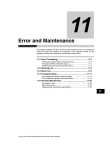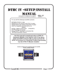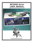
1
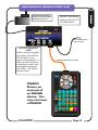
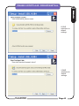
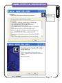
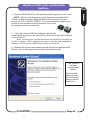
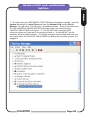
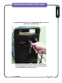
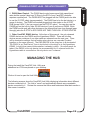
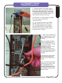
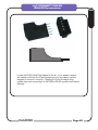
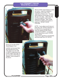
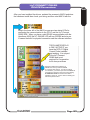
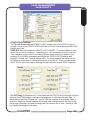
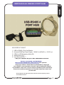
USER MANUAL RS485 4 PORT HUB
Introduction
AX
INCLUDED IN THIS KIT:
1.
2.
3.
4.
5.
USB to RS485 4 Port Hub Module
Universal WallPlug Power Supply. 100VAC to 240VAC in ; 5V DC out
USB A to USB B interface fable (6ft )
Installer/driver CD **
User Manual (PDF) **
** May be on Master Support CD in RS-485Hub4 Folder
Version 1.0 DATE: 10/30/2012
See www.CandCNC.com/Manuals.htm for updates
Copyright notics: All content is protected by copyright
Any reuse or reproduction in whole or part witout permission
is prohibited. Any user manual may be rpinted in part ot whole by
the owner of the prodiucts cover bay tha manual for their own
private use.
Any trademark or logo used in this manual is the the property of the
the tradmark owner
CandCNC
Page 1
USB- RS485 4 PORT HUB
Plug Locations and Layout
Introduction
AX
RS485 4 PORT HUB (TOP VIEW)
PWR
Con ACT
USB
RS485 4 PORT HUB
(END VIEW)
RS485 4 PORT HUB (FRONT VIEW)
CandCNC
Page 2
USER MANUAL RS485 4 PORT HUB
Universal AC power Plug
100VAC to 240VAC 50/60HZ
Regulated 5V @ 1A out
PWR
USB ACT LED shows
Valid connection to PC
on USB channel
Con ACT
USB
To EPO on ESP front panel
or EPO on Table I/O
ACTIVITY MONITOR
LEDS
When a device is plugged
into a port on the hub the
LED will light if it has
proper communications. It
does not mean the device
is operating correctly (see
later pages for using the
Hub Utility). The Activity
Monitor shows
Standard CAT5 UTP up to 50ft
T
OPOR IONAL
PR
JO
0°
E-STOP
G
PN200
36
CandCNC
CNC HAND
CONTROL
PN200
Shown as
example of
an RS485
device. You
may not have
a PN200
JOG
AXIS
COM
OK
THC ON/OFF
PUSH
CREASE
IN
SPEED
ZERO
REF
X
Y
MACRO TOUCH
OFF
M
1
INTER
LOAD
LOCK Material
DTHC PRESET
-
PUSH to RESET
CREASE
IN
4
SPACE
ENTER
7
JOG
SPEED
Z
A
B
Z
UP
Y+
IN
YOUT
2
Z
DWN
5
3
F
X+
OUT
XIN
6
G
8
9
.
TOGGLE
STOP
ENTER DELETE
CandCNC
Single
Step
SCREEN REF XY OUTPUT OUTPUT TORCH/
SPINDLE
3
2
EXECUTE
FEED
RATE
Step
Inc
RUN/
PAUSE
0
MODE RESET
STAY AWAY FROM MOVING MACHINERY
Page 3
Introduction
AX
CONNECTION EXAMPLES
CONTROLLER
PC
RS485 4
Port Hub
USB
PN200
UBOB
Mark IV
CandCNC
RS485
Cards
Quad
Relay IV
LS I/O
HYPERTHERM
65/85/105
with RS485 Port
EZPlug II
SERVO
CandCNC
Spindle
SSpeed
Mark IV
CandCNC
RS485
Cards
DTHC
Mark IV
NOTE: Example ONLY
some of the examples are
not available yet. Names
may change and release
dates are not yet scheduled
Page 4
Introduction
AX
RS485 4 PORT HUB - DRIVER INSTALL
SOFTWARE
AX
Before plugging in your USB-RS485 4 Port Hub to you USB port
on the Control PC use the following steps to first install the USB
driver (required one time).
1. If you have plugged in the USB-485 4 Port Hub to your PC
UNPLUG it at this time and leave it unplugged until you are instruced
to plug it in
2. Load the support CD for the 4 Port Hub (or go to the 4 Port Hub
Folder on the Main Support CD that came with your unit
(BladeRunner or MP3000).
CandCNC
Page 5
RS485 4 PORT HUB - DRIVER INSTALL
INSTALLING THE USB-RS485 4 PORT HUB
SOFTWARE
AX
LEAVE
selections to
default
settings
LEAVE
selections to
default
settings
CandCNC
Page 6
RS485 4 PORT HUB - DRIVER INSTALL
INSTALLING THE USB-RS485 4 PORT HUB
Introduction
AX
READ THe
INSTRUCIONS
CandCNC
Page 7
RS485 4 PORT HUB - HARDWARE
INSTALL
4. Plug the USB-RS485 4 Port Hub wall plug power supply into an AC outlet
NOTE: While the wall plug power supply has pins for standard US AC
120VAC sockets the power supply will work and run from any AC power
source from 100 to 240VAC 50/60HZ. You can purchase plug adapters from
several on-line merchants including Amazon ,com for less than $2.00
No voltage conversion is necessary.
5. . Using the included USB A to B adapter cable plug the B plug into the
matching jack at the end of the hub and the other end into any open USB jack
on the control PC,
Note: for testing you can load the drivers and CandCNC Hub Utility on
any PC or Laptop. . but for operation you need to have the hub installed and
working in the PC that runs MACH and controls you machine
6.. Windows will see the new hardware and will launch the Hardware Install
Wizard. Use the following screens to finish the hardware install
First Screen of
Hardware
Install(Update)
Wizard.
Leave the radio
button set on the
“No, Not this time”
option and hit the
Next Button....
CandCNC
Page 8
Hardware
AX
RS485 4 PORT HUB - HARDWARE
INSTALL
Next Screen of
Hardware
Install(Update)
Wizard.
Leave the radio button
set on the
“Install the software
automatically”
option and hit the
Next Button....the
driver has already
been installed in the
earlier steps so you do
This completes the
software and driver
install for the
CandCNC USB to
RS485 4 port Hub.
See the following
pages for checking
the install and to
use the CandCNC
Hub Utility (Admin
CandCNC
Page 9
Introduction
AX
RS485 4 PORT HUB - HARDWARE
INSTALL
Hardware
AX
7. To confirm that your USB-RS485 4 PORT HUB drivers have been installed, open the
System Application in Control Panel and then the Hardware Tab and the Device
Manager. You will see a “Tree Structure” of hardware devices. Scroll to the bottom and
Find the UNIVERSAL SERIAL BUS DEVICES and under it you should see the
CandCNC USB to RS485 hub device. IF YOU DO NOT then unplug the USB
connector (either end ) and wait 5 sec and plug it back in. You should NOT get the
Hardware Install or Update Wizard . The Device manager should update and show you
the screen below.The CandCNC USB to RS485 hub device will only show up when it is
plugged in
CandCNC
Page 10
RS485 4 PORT HUB - DEVICE CONNECT
The USB Active (ACT) LED only comes on
when there is a valid USB connection to the
PC. Drivers have to be loaded and active.
USB ACTIVE LED
PWR
Con ACT
USB B plug to PC
USB
INSTALLING CandCNC RS485 Devices to the USB-RS485 4 PORT HUB
The USB-RS485 4 PORT HUB has an advanced processor than can communicate
with several RS485 devices. RS485 is a robust and noise-immune communications
standard used in industrial electronics for years. Because of its differential signal
methods it is unaffected by external or ground based noise and reliable
communications of several hundred feet are common. RS485 is a multi-drop
topology meaning there can be multiple devices on the same pair of wires as long as
all of the devices operate at the same speed (BAUD RATE) and have a unique
address. Since USB is a common port on most PC’s it is a logical choice for
communications that do not depend on precise timing.
You will note that the USB-RS485 4 Port Hub has four in dependant channels ad
each channel can talk to multiple devices, Because of different Baud Rates or
special signals the 4 port hub has two special jacks:
1. Hypertherm RS485 Port. This channel runs at a much slower speed and can
only talk to a Hypertherm Plasma Cutter equipped with an RS485 port (optional) and
through our HyT-Connect RS485 interface. If you already have the HyT-Connect
RS485 SIM Kit installed and have the older RS485 module you need to unplug the
existing setup and plug the RJ45 (Cat5) cable FROM the port on the rear of the
Hypertherm into the jack 1 marked “To Hypertherm Rs485 PORT (Only)
CandCNC
Page 11
Hardware
AX
USER MANUAL RS485 4 PORT HUB
Introduction
AX
Plugging RS485 Hypertherm into RS485 PORT on back of
Hypertherm 65/85/105
See HyT-Connect Manual for details on installing and
using the RS485 remote control for the Hypertherm
and the DCC (Dynamic Cut Control)
CandCNC
Page 12
RS485 4 PORT HUB - DEVICE CONNECT
2. PN200 Hand Control. The PN200 hand control uses normal high speed baud
rates but the special “dead man” E-Stop to the EPO of any CandCNC controller
requires a special jack. The PN200 MUST be plugged into the PN200 jack to be able
to use the E-STOP safety (recommended). The PN200 has to be the last device in a
group of devices. The PN200 will worked plugged inot other jacks on the 4 PORT
HUB (except JACK 1) but you cannot use the E-STOP option. You can also use the
PN200 jack on the hub for other RS 485 devices if you do not have a PN200. While
the PN200 would work with other devices on the channel that have loop through (pass
through) jacks the E-STOP to EPO DOES NOT PASS THROUGH OTHER DEVICES
3. Other CandCNC RS485 deivies. At the time of this manual, the only released
RS485 devices are the PN200 and the Hypertherm RS485. There will be other
devices as new revisions of our other cards are released over the next year. There
will be termination settings that will matter when devices are cascaded (hooked
together on the same channel). The END DEVICE in the string has to be terminated.
The PN200 is an “End Device” (has to be the last in the string) as is the Hypertherm
RS485. In both those cases the termination is already in place.. No action needs be
taken if the PN200 is the only device (as recommended) on it’s channel and/or the
Hypertherm cable is connected as the only device on it’s channel.
MANAGING THE HUB
During the install the CandCNC Hub Utility was
added and an ICON was placed on your desktop.
Click on th icon to open the Hub Utility.
The following screens show the CandCNC Hub Utility displaying information about different
devices connected to it. The Hub is “smart” and automatically detects any compatable
device connected to it. Review the screens that follow and understand what each section o
fthe screen is used for.
CandCNC
Page 13
Introduction
AX
HUB MANAGMENT
HUB UTILITY
AX
DEVICE DETAILS
Provides the:
Device Name
Device Code: Each
CLASS (type) of device
has a different Device
CODE Codes can be from
1 to 99.
Device Address: The
unique address of a device
within a class (values from
1 to 8).. Devices of the
same type must have a
different Device Address.
Future cards will have
address jumpers to allow
multiple cards of the same
type to work on the same
hub.
Firmware Version: This
displays the current
DEVICES:
Shows a list of
connected
devices. As a
device is
connected and
sensed by the
hub it will appear
in the list. If you
connect a device
and it does not
show up
immediately,
Hub Connected
(to USB on PC)
Displays current
firmware of the HUB.
This MUST show
connected status
before any other of the
functions will display
TEST DEVICE
Action button that
opens a new
dialog window.
You must have a
device
highlighted in the
Devices List to
DEVICE TESTING: Hypertherm RS485
VIA HyT-Connect RS485 SIM
Update Device Firmware.
This allows you to update
each module with new
firmware. New firmware
will be designated by a
REV number. Firmware
updates will be available
for down load in a special
download section of the
CandCNC website and on
the Yahoo
CandCNCSupport Forum.
HYPERTHERM TEST
Shows connection and
communication to/from the
Hypertherm RS485 Port tot
he USB-RS495 4 Port Hub.
Any fault message will
display (in this case air was
not hooked up and it shows a
“No Gas Input error)
To test you can input a
Current in AMPS) and send it
using the Send Current
button. the LCD display on
the Hypertherm should show
the new value. Other values
are tose read from the
CandCNC
Page 14
HUB MANAGMENT
UPDATING HUB FIRMWARE
HUB UTILITY
To update the USB-RS485 Hub Firmware you must:
1. Download a designated file from the CandCNC Website (Product Support Tab) and
place it in a named folder on the machine that has the hub attached. Select the MISC tab
at the top and you will have an Update Hub Firmware choice (other choices for other
functions may be added later)
2 Click on the Update Hub Firmware and a File Navigation window will open and you can
navigate to the file in the folder you have downloaded the new firmware to. The file
extension for all Firmware updates will be ucccx. Highlight the file to use and hit the
OPEN button. The Hub Utility will automatically update the hub firmware.
CandCNC
15
Page 16
Introduction
AX
MACH SETUP
UPDATING HUB FIRMWARE
RS485 HUB
AX
1. Once you have the USB-485 module installed, you have confirmed the drivers
are install correctly , you know the correct COM number and , the screen files
updated, Start MACH3 (if it is not already running) and Load the MACH3 Profile you
normally use. If you use more than one you will need to do the check, load screens
and settings on EACH PROFILE.
2. Use the Upper Toolbar and select the “Config” menus option. From the Drop
Down List Box select the “Config Plugins” menus option
CandCNC
Page 18
Introduction
FINAL INSTALL : MACH3 Setups
MACH SETUP
UPDATING HUB FIRMWARE
RS485 HUB
Introduction
AX
3. You will see a Menu window similar to the one above. NOTE the
ccc_rs485 plugin IS FOR THE PN200 and will not show up if you do not
have the PN200 installed. The HyT-Connect install does not add a new
plug-in, it updates the ccc_comm plugin
4, The Enabled column for the ccc_comm should be enabled (green
check) if not enable it.
5. Before you click “OK” open the CONFIG dialog for the ccc_comm by
clicking on the yellow CONFIG bar on the same line(row).
Shows
DTHC is
This is the COM
Port for the DTHC
and the Power
Supply dashboard
Note that there are now three tabs for configuration. The Hardware
Connections should be the same. COM1 is usually the PC serial port used
CandCNC
Page 19
PLUG-IN CONFIG
HT-CONNECT
AX
6. Click the HT-Connect Tab in the Window. Your information
may be different that what is shown. The IMPORTANT
parameter you need to set is the RS485 port. Make sure you
have the correct COM port number selected
MACH Plug-in configuration (ccc_comm)
CONFIGPLUGINS/CONFIG/HT-CONNECT TAB
COM Port the HyT-Connect RS485
is installed to. See details below.
Current connection status
shows ‘Connected when com
line is active
Same as
CUT PROFILE
setting
Shows Status of Serial connection
to the Hypertherm (same as HT ONLINE)
These parameters are read from the
Plasma Unit when the plasma is
connected and the PC is communicating
with the Hypertherm RS485 Serial Port
and sets the min and max values allowed
for the Current and Air pressure.
Which port do I use?. When you do the auto install of the new USB-RS485 4 Port Hub package it
will add in the USB port as a selection in the list.. MAKE SURE YOU SELECT USB as the port to use
for HT Connect. Also open the plug-ins for the ccc_usb-rs485. it will display the connected devices
and you can choose to configure them. The older single port models used COM ports. The new one
does NOT and uses the USB port direct/
CandCNC
Page 18
HUB MANAGMENT
HUB UTILITY
AX
IMPORTANT INFORMATION:
Anytime you make changes to a MACH3 setting it is not saved in the Profile (XML)
until you exit (shutdown normally) MACH3. Some settings take effect immediately.
A CHANGE IN A PLUG-IN DOES NOT TAKE EFFECT UNTIL YOU STOP AND
RESTART MACH3. AFTER YOU MAKE THE CHANGES TO THE PLUG-IN
L:ISTED, STOP MACH (End Session - Yes) and Restart MACH with the same
Profile.
The following section shows the
setup and connection for the
HyT-Connect RS485 SIM Kit
this supercedes the HyT-Connect
Manual
CandCNC
Page 19
HyT-CONNECT RS485
DEVICE Connections
AX
9. With the module under power (green
power LED will be on) locate the USB A to
B cable provided with the kit. Connect the
“B: (square) end of the cable to the plug in
the end of the USN to RS485 module. It is
keyed and will only go in one way.
NOTE: Photo is of older single port RS485
hub. See previous sections for
connection points
10. You may want to secure the USB to
RS485 module to the top or side of your
PC. The best method is to is a strip of
adhesive backed Velcro on each side so
the module can be up out of the way but
easily removed if needed
11. Find an open USB jack on
your PC and plug the “A” end
of the USB A to B cable into
that jack.
When you plug the powered
USB into a USB jack on the
PC and if Windows is running
it will pop up a “New
Hardware Found” box, but it
will install the device
automatically (provided you
have done the software install
on pages ## thur ## in this
manual).
At this point you may want to
go back and verify that the
settings in the COM ports on
the PC.
Note: If you have the drivers
loaded and the correct COM
port is designated in the
ccc_comm Plugin, then you
will start to see activity on the
ACT USB LED of the USB to
RS485 module.
CandCNC
Page 20
HyT-CONNECT RS485
DEVICE Connections
AX
Locate the 65/85 Serial Plug Adapter in the kit. If you need to remove
the adapter card from the 5 pin Eurostyle plug for any reason use the
diagram to connect it correctly. Plugging it in to the Eurostyle plug
upside down and connecting it to the USB to RS485 module could cause
damage.
CandCNC
Page
Page21
23
HyT-CONNECT RS485
DEVICE Connections
AX
With the 65/85 serial adapter module
as shown , locate the matching
receptacle on the rear of the
Hypertherm Plasma unit. The plug
and receptacle are keyed so it only
will go in one way.. Insert the plug
into the receptacle until it seats
against the flanges. With a small
screwdriver tighten the screws on
each end. DO NOT OVER
TIGHTEN.
NOTE: If your plasma unit does not
have the 5 pin vertical receptacle on
the back then your unit does not
have the optional RS485 Serial
Interface Kit installed. If you have
the kit (Hypertherm part # 223036)
use the file at:
https://www.hypertherm.com/Xnet/lib
rary/library.jsp?file=HYP109750
Once you have the 65/85
Serial Adapter Card
installed and secured take
the opposite end of the
UTP cable from the USB
to RS485 module and plug
inot the open RJ45 jack on
the end of the 65/85 Serial
Adapter Card as shown in
the photo.
CandCNC
Page 24
22
Page
HyT-CONNECT RS485
DEVICE Connections
AX
After you have installed the drivers, updated the screens in MACH and done
the hardware install then check your wiring and then start MACH with the
Note in the lower left of the MACH screen are two status LESs for
confirming the communication to the DTHC and the HyT-Connect
RS485 SIM. When you have a valid RS485 communication with the
Hpertherm 65/85 the HT ONLINE LED will tunr GREEN and stay on.
It means the botht he physical connection and the software interface
TORCH AMPS DISPLAY
is ONLY ACTIVE IF you
have the DCP-01 Digital
Current Probe installed
and working. It is not part
of the HyT-Connect
RS485 and is not
required for it’s operation
but it does provide an
Shows the AMPS the Hypertherm is
set for when the HyT-Connect RS485
is connected and working. You cannot change
it in the DRO...you have to open the CUT PROFILE
and make the changes in the CUT Current setting.
IT DOES NOT show the actual current that is
happening at the cut. It is the same as reading the
dial on the plasma cutter.
CandCNC
Page 23
HyT-CONNECT RS485
DEVICE Connections
AX
To open the CUT PROFILES dialog window shown above click on the
SETTINGS(Cut Profile) button on the Program Run screen.
For more detail about what all of the settings mean and
what they do, refer to the DTHCII Users Manual. This
section will cover settings associated with the HyTConnect RS485 SIM.
CUT CURRENT. This is the “PRESET” current in AMPS and is the value the RS485
sends to the Hypertherm via the RS485 com link. The value that the Hypertherm
returns that it is set to shows up in the PRESET AMPS on the Main Screen.
CUT TOLERANCE. Is the amount of deviation in PERCENT that the control will
allow in the CUT CURRENT before it triggers a FAULT. The falut will turn on the
AMPS out of RANGE LED and the cut will contunue. You can set an ACTION (what
happens if the current faults) and make it STOP the cut as an option. CUT
TOLERANCE IS ONLY USABLE IDF YOU HAVE THE DCP-01 and can read the
CandCNC
Page 24
HUB MANAGMENT
HUB UTILITY
AX
OTHER DTHCII Settings:
The Tip Volt Preset sets the PRESET VOLTS (target volts for the DTHC to use to
compare to the actual TORCH VOLTS from the cut and to use to adjust the ARC GAP
(height) as it cuts.
SPAN GAP Sets the sensitivity of the TIP VOLT PRESET. It creates a Span of volts
where the control is in balance. The setting is in 1/4V increments so 4/4 is one volt.
That translates to the control in the setting shown below would be in balance (not
sending UP or DOWN commands) as long as the TORCH VOLTS reading was
between 141 and 139. Normal setting is 4/4. On some material that value can be
set tighter or more loose to change the reaction of the DTHC. Each volt represents
about .015 to .020 of arc gap so settings too high will result in poor DTHC response.
The THC Delay (in firmware rev 1.2 and higher on the DTHCII) sets the length of time in
seconds the DTHCII delays reacting to the variations in volts after the torch fires. It
alsow delays the FAULT signals for 1 sec AFTER the duration of the primary delay. It
should be longer for thicker material and should allow enough time for the torch to fire,
the plunge from pierce to intital cut height and for a normal cut to start. Default is 1sec
but raising that lengthens the delay .
CandCNC
Page 25
HUB MANAGMENT
HUB UTILITY
AX
ARC OK CURRENT. The “trip point” for ARC OK signal to turn on (sends ARC OK
to MACH ). YOU MUST HAVE THE DCP-01 Digital Current Probe providing the
actual Cut Current before this value has any function. The Hypertherm 65 and 85
have the ARC OK (TRANSFER) signal available and that is normally used as the
ARC OK signal. The two signals are in parallel so EITHER will trip the ARC OK.
AIR PRESSURE. This is an HYT-Connect RS485 SIM feature ONLY. IT shows the
pressure that has been set at the Hypertherm in PSI. There is no feedback value
(actual air pressure indicator) so the value is the same as reading the value on the
LCD.
NOTE: This section may be outdated if you have upgraded to
the newer DCC (Dynamic Cut Control) version.
CandCNC
Page 26