Download DTHC IV -SETUP/INSTALL MANUAL
Transcript
DTHC IV -SETUP/INSTALL
MANUAL REV .07
PRELIMINARY
Jan 2014
For use with the following CandCNC products:
MP3000E-DTHCIV or later
BladeRunner (all versions) with DTHC IV option
Plazpak Series (all versions) with DTHC IV option
Ether-Cut Upgrades all series (DTHC IV)
Options
DCP-01 Digital Current Probe (11/02/2010)
DCC Dynamic Cut Control
HyT-Connect Hypertherm Connection Kits
TAP Total Automation Plasma
Use this manual to install and setup a DTHC IV
Expansion Module in the field for any of the above
listed CandCNC products OR to setup and test the
DTHC IV functions in a CandCNC Product that already
has the DTHC IV Module installed.
Includes complete setup and testing of the new CandNC
DIGITAL CURRENT PROBE
+15V
-15V
ACT
CAL
Plasma
Unit
TEST
20 - 125A
Workclamp
Lead
DC AMPS
CLAMP
CandCNC
DIGITAL CURRENT PROBE
Model DCP-01
CandCNC
Page: 1
TABLE OF CONTENTS
I. Introduction
DTHCIV Features List
THC Basics
2-3
II. Overview
Module ID
Correct Block Diagram
Expanded Block Diagram
Outline Steps
4-8
III. Software Install
Master Installer II
9-10
IV. Hardware Install
A. C3 BUS 4 Port Hub
1. Introduction
2. Install
B. Hub Management - Setup
1. Hub Utility
2. Z Motor Settings
C. Hub Management - Setup (cont.)
1.
2.
3. Firmware Upgrade
4. Device Testing
11-25
V. Setting up Ethercut
26-38
A. Install
1. Screen Sets for DTHCIV and Ethercut
2. Ethercut Hardware - Ethernet Port XP
a. Network Adapters
b. Network Connections
c. TCP/IP Address
3. Ethercut Hardware - IP Ethernet for WIN7
a. Local Area Connection
b. TCP/IP Address
4. Connection Schematic
5. Optional Ping Test of Ethernet
B. Modules Setup
39-42
1. DTHCIV Module
a. Install DTHCIV
b. ID of DTHC Plugs and Indicators
c. Front Panel Indicator Chart
2. DTHCIV Cut Profiles
43-50
a. Accessing Cut Profiles via Mach3 Screen
b. Basic Cut Profile Display
1. Current DTHC Settings
c. DTHCIV Settings Tab
1. Preset tuning - DTHC Sensitivity - DTHC Tracking
2. Other DTHC Settings
3. General Settings
d. DTHC Motor Tuning
1. Display - Info Only
3. PWM Module Setup
1-57
a. Older Model Divide Ration Settings
b. New Model 21 Divide Ratio Settings
c. Test Calibration
1. Older Module Volts Test
2. Newer Module Volts Test
d. ARC OK Test
CandCNC
Page: 2
TABLE OF CONTENTS (cont.)
C. Making Connections to your Plasma Cutter
1. Connecting using Universal Connection Kit
2. Making Connections to Plasma
a. Finding the Correct Connections
b. Firing to Torch
c. Testing/Troubleshooting RAV-01
d. Hypertherm 1000/1250/1150 Connection Points
e. Connection to Hypertherm 45
3. Making Connections via External Connections
a. Thermal Dynamics
1. CPC Pinout
2. Automation Interface PC Board
3. A Series Pin Outs
b. Hypertherm
1. CPC Pinout 45/65/85/105/125
2. Divider Switch Settings
58-67
VI. Setting Up and Plasma Cutting with DTHCIV
A. Setting Up the Z Axis for Automatic Touchoff
1. Modifying SheetCam Post for Switch Offset and Ref Difference
B. Z Motor Tuning for Best Performance
C. DTHC Screen: Buttons and DRO Functions
1. Base DTHC Screen Elements
2. TAB Fly-out on DTHC Screens
3. DCP Option
a. Indicators
b. Cut Current Troubleshooting
D. Cut Profiles Screens
1. Define Terms
2. Adding Profiles
E. Final Testing
1. Startup Test - Manual Cut
2. Using SheetCam to Generate Code
VII. Addendums
A. Adding Digital Current Probe
B. Grounding Practices
C. Adding HYT Connect Rs485 for Hyperterm
D. Troubleshooting DTHCIV Problems
E. Adding FT-01 Feather Touch Ohmic Sensor
CandCNC
Page: 3
FEATURES GUIDE FOR DTHCIV
This document describes a product from CandCNC that provides a new approach to
Automated Torch Height Control. The DTHC MARK IV system is backwardly
compatible with earlier CandCNC controllers using the DTHCII. The DTHC MARK IV is
a 4th generation design using a faster more complex microprocessor and is the
culmination of over 10 years of THC designs from the engineering team at CandCNC,
and is the pentacle of high performance / low cost digital torch height control.
The DTHC IV has the following features: *(new features in RED)
Σ
Σ Compact Surface Mount Design.
High Speed Processor, Boot Loader on chip for easy firmware
updates
Σ Uses ECC (Electronic Cut Chart) for stored settings. (2)
Σ RS485 C3Bus® communication using standard UTP cabling (CAT 5) (2)
Σ Isolated external HOLD circuit. No other inputs on BoB used or needed
Σ Works with MACH3 and LinuxCNC (3)
Σ Single Operator Console for all CNC settings and operations....no knobs , no manual settings.
Σ Supports Dynamic Cut Control on all plasma cutters (2)
Σ Usable with virtually any plasma cutter with or without CNC connectors (4)
Σ Z motion speeds of 200 IPM with STEPPERS!
Σ Setup and testing via RS485 and Windows/Linux app “HUB UTILITY”(1)
Σ Z Response tuning has true PID settings to prevent overshoot and instability
Σ 6 Presets for response tuning cover most types of cutting and Z mechanical types.
Σ Plug compatible with existing CandCNC MP3000’s and BladeRunner/Plazpaks after Aug 2012 (1)(5)
Σ Works with all forms of pulse interface (Parallel Port; USB; Ethernet) (4)(6)
Σ More than 5X faster than systems using MACH3 THC logic
Σ Engineered to do extreme cutting including corrugated and HVAC type materials
Σ Unique Patent Pending Hybrid Design shares single Z axis allowing G-Code position control mixed
(1) Requires optional USB to RS485 4 Port C3BUS Hub from CandCNC
(2) Requires SheetCAM TNG and custom CandCNC POST Processor
(3) MACH3 only until 2014. Contact CandCNC for more information.
(4) May require other options/ connection kits
(5) Upgrade kits available
(6) USB not recommended for most installs.
CandCNC
Page: 4
Some torches will have more than one set of small wires
for other sensors in the head. Confirm switch pair with an ohmmeter
while operating the switch (Plasma Unit power OFF)
NOTE: Machine Torches
operate the same but do
not have a switch in the
torch to fire it.
Air and/or tip voltage
Hi Volts
Workpiece Clamp
Good connection to the workpiece with clamp is essential
for proper operation of the THC
Torch Switch Wires
HOW DTHC (THC/AVC/DTHC) WORKS
Automatic Torch Height Control (often called just THC) works by reading the Arc Gap Voltage while cutting.
Plasma uses constant current cutting. If the current stays constant and you vary the gap (either by moving
the torch or moving the material UP or DOWN) then the voltage will change in proportion to the change in
arc gap. Much like the altimeter on a plane (that measures barometric pressure to determine altitude) the
Arc voltage indicates the RELATIVE distance from the end (tip) of the nozzle to the top of the material.
The change in voltage for a change in height is a small percentage of the overall cutting voltage. A 1%
change in voltage (100 to 101 volts) is equal to several thousands (typically .015 or more) of arc gap
change so the THC must be able to see and act on a small change in a large number.
The THC control must take the actual cut voltage and compare it to a preset “target” and move the Torch
Up or Down to try and correct the height based on it’s arc voltage. The process forms a “servo loop”
where an “error” voltage from a preset is used to physically move the torch Up or Down to “correct” the
error. Under normal cutting conditions the voltage stays constant with height but certain conditions that
effect the arc gap voltage can skew the gap volts and case the THC circuit to overreact. The feed rate
(how fast the tip is moving across the material) determines the current density and the Gap Volts. A
slower feed rate will cause an increase in Torch Volts (if no THC servo is there to correct). With THC
engaged the circuit will sense the higher voltage and based on the error created lower the torch to try and
compensate. This occurs if the arc crosses a void or existing kerf or at the end of a cut when the scrap
drops out. The DTHCII includes an adjustable Anti-Dive (Tip Saver) that senses a rapid voltage spike and
locks down motion.
? Arc Gap = Arc volts=Torch Volts
? 1volt (change) = approx .015”(change)
? >Arc volts = > Arc Gap. (greater the Arc Gap the
greater the Arc Volts)
? Z moves opposite Arc Volts based on Preset Volts.
Torch Volts Above Preset: LOWERS torch; Torch Volts
below Preset: RAISES torch.
? Control has “window” (Span Volts) where no UP or
DOWN occurs. (prefect cut height) Anything inside the
Span (+ or -) from the Preset generates NO change.
SPAN VOLTS is set in 1/4V increments in the Cut Profile
CandCNC
Arc Gap
-
Gap Volts
+
Page: 5
OVERVIEW
C3BUS™ USB to RS485 4 Port Hub
See text for details
The following pages will cover the identification, hookup, setup and testing of the DTHCII Digital Torch Height
Control System. Each card/mosule has a specific function and set of tests. A minimum system will consists of a
DTHC II Expansion Module (interfaced to a CandCNC UBOB III Universal Breakout Board) and the THC Sensor
PWM Module.
The DTHC IV is a later version of our popular DTHC II that was introduced in 2011, and is the 3rd
generation DTHC and the 4th generation of Digital THC’s from CandCNC. The DTHC line has always been a
feature-rich product with advanced technology based on powerful embedded processor chips and modern
surface mount components. From the innovative Total Isolation (including the analog Arc Volts readings) to the
Self-test and built in “Tip Saver” anti-dive the DTHC has earned a reputation for being solid, reliable and userfriendly, while offering the operator a wide range of options for precise cutting with plasma and all at a very
effective price.
The DTHC IV builds on that success by making the product faster, with more features and the first ever
“Shared Z “ design for MACH3 for access Automation control signals in the plasma. Using the same PWM
Module as the DTHCII, it takes a divided Arc Volts signal (available as an option on several plasma models or
from our Optional RAV-01 card) and changes the small analog signal to a constant level PWM signal that is
many times more immune to external noise and EMF problems. Designed to work with your existing equipment
including HF and CD start units or the most modern plasma units in built-in Automation Interfaces, it sets a new
standard for Torch Height Control. You can pay MORE for a THC but cannot get more features or accuracy than
the DTHC IV offers.
CandCNC
Page: 6
OVERVIEW
BLOCK DIAGRAM TYPICAL DTHC IV
HOOKUP for Automation Interface
DCP-01
(option)
for ARC OK
Used for ARC Current
Readout; NOT Required
DTHC IV
Module
Cat5 UTP cable
UP to 25 ft
PWM MODULE
Plasma Pickup Module
Located external and
close to the Plasma cutter
Located in the control
box with the UBOB III
card
MIC-01 Custom Cable
CPC Plug
on Plasma
Unit
CandCNC
Single cable
Hookup to
Plasma Unit
Page: 7
CandCNC
RS485
4 PORT
Hub
Input/Outputs
Homes/Limits
Probe/relays
DTHC IV
HyT-Connect Control Interface
DTHC Control Interface
A
Y
X
Z Step to Motor Driver
Z Step from Interface
** USB motion interface products
NOT recommend for plasma
CNC installs due to possible noise
issues
RS485
RS485
Motor
Driver
Z axis Breakout
For existing CandCNC
Controls
Step & Dir signals
Interface
Circuit
USB **, Ethernet
PPort,etc
USB
The NEW CandCNC DTHC iV
takes all of the features of the
DTHCII and brings a hybrid
shared control of the Z axis.
DTHC functions and motion are
directly controlled by the DTHC
IV, and as a result, are much
faster and tunable. The THC
loop is now closed at the DTHC
IV so there is no longer a
requirement for the THC logic
in MACH3 nor for a real-time
high speed set of inputs. It still
offers the same high level
operator interface and the
Advanced DCC and TAP options
and still allows full plasma
NOTES:
Screen feedback of
all motion and
DTHC Readouts
Including Hypertherm
faults and settings*
Software Control of
Motion, DTHC functions
MACH3
LINUXCNC
50 + ft
RS485
Torch Swtich
and Arc OK
local connections
RAW ARC VOLTS
(voltage Divider)
RAV-01 Option
Mounted
internally and
used on units
that do not have
an voltage
divider.
RS485 Port
OPTION
Hypertherm Only
CPC
Connector
OVERVIEW
FULL Z axis
Router/Torch/Cutter
Okay to Move
Divided Volts
PLASMA
CUTTER
See CandCNC
CONNECTION KITS
for interface options to
different plasma
cutters. Not all plasma
cutters have external
connection ports and
require connection
options
Torch Fire
PWM
Module
A/D
pickup
NEW DTHC IV BASED CONFIGURATION
FULL SYSTEM BLOCK DIAGRAM
Z
Page: 8
INSTALL OUTLINE
SIMPLIFIED SETUP STEPS
SETUP OUTLINE
1.Install or update and verify Mach3 version 3.043.067 (on CD
2. Use Master Installer II to install the products you have
3. Install C3 BUS Hub and test that hub utility works and uses the hub.
4. Update the hub firmware if needed.
5. For Ethercut products, follow the IP setup and testing procedures.
6. Plug all components together per diagram.
7. Use Motor Tuning section in BladeRunner AIO User Manual to setup motors.
8. Test JOG and Simple G-Code (MDI) motion commands.
9. Use DTHCIV Setup and Config Manual section _____ to test and calibrate the Z
tuning for DTHC operation.
10. Use DTHCIV to install the Connection Kit Modules and run tests to confirm
operation.
11. Make connections to plasma cutter.
12. Run simple tests with DTHC OFF cutting metal to get baseline numbers and
confirm configurations.
13. Install SheetCam TNG (can be same PC on Ethercut systems).
14. Install SheetCam CandCNC Support file.
15. Generate simple shapes files using correct post in SheetCam TNG and perform
test cuts.
CandCNC
Page: 9
Open MACH with either the DTHC IV or the Ether-Cut profile (Icon) depending on which
product(s) you have. For Just DTHCIV (parallel port setup skip the next step)
!
For the Ether-Cut install (which includes the DTHC IV) Check that the ESS plug-in is
working in MACH3 The Plug-In Control tab (top menu in MACH) should have several ESS
choices in the list. If the Ether-Cut was not working you would not see the selections in the
Plug-In Control List Box. DO NOT OPEN THE SELECTIONS in the list and make ANY
changes. The IP address WILL NOT display right even if you have communications . There
are indicators on the front of the Ether-Cut clustered around the Ethernet Jack that can be
used to confirm connection and valid communications (see the chart in this manual)
!
Do some preliminary motion checks, If this is a new install and you have no motor tuning
numbers to go from, refer to the Motor Tuning Section of the BladeRunner AIO User
Manual (even if you have just the MP3100-DTHCIV MP3500-DTHCIV EtherCut version or a
Plazpak).
!
! Continue through the DTHC IV Setup and Config Manual to do the testing and fine tuning
of the DTHC IV. There are settings and tuning requirements for the DTHC IV that are
different than the DTHC II.
IMPORTANT! IF you are moving from a DTHC or DTHCII to the DTHCIV it is a radically
different system and requires the tuning steps outlined in Chapter____ of this manual
If you skip this than your results will be less than optimal.
CandCNC
Page: 10
INSTALL OUTLINE
LIST of STEPS to SETUP DTHC IV
and ETHER-CUT SYSTEMS
Using the Auto Installers for CandCNC
DTHC IV and EtherCut Controls
MENU SCREEN FROM MasterInstallerIII .exe...RUN THIS FIRST
SELECT THE PRODUCTS TO INSTALL YOU HAVE
1
IF you are upgrading an older setup make sure you first backup your MACH3 folder to a
memory stick and THEN upgrade MACH to version 3.043.067 or later and run the Master
Installer III FIRST. Do not select products you don’t have or that you used to have Either
install the proper DTHC IV product or the Ether-Cut product you have
but NOT BOTH.
After you have installed the Master installer and have the icons for the products and can
open the profile to indicate you got a successful install, You can come back and install again
but it will put any profiel back to defautl values and any cahnges you have made (like motor
tuning and axis settings in MACH) will be abck to the default values
If you need to recover your motor tuning simply open the MACH folder off your memory
stick and copy your old working profile back into the MACH folder on your computer. Most
of the settings are totally different (Ports & pins for example) so use only the motor tuning
VALUES in the new Profiles.
NOTE : MACH keeps backup copies of the XML profiles any time you make changes
They are stored in a folder under MACH named XMLBACKUPS. In that folder you will find
Files like “ETHER-CUT+TAP.xb11” . the suffix (after the dot) are xb+ the version. To
recover you can find the highest ver number and rename it with the “xml” suffex. First copy
it to the main MACH folder as the xb# extension and then rename it . If you have one
already named that it will refuse so first remane the XML file if that name to something like
.default than rename the file you copied in/
CandCNC
Page: 11
2
New PROFILES (ICONS) will be added to
your desktop. You may have other CandCNC
profiles from earlier installs.
If you do not have at least one of the new ICONS as
shown above after running the DTHCIV+EtherCut_Install it
was not done correctly. Do the install again
CandCNC
Page: 12
INSTALL
Using the Auto Installers for CandCNC
DTHC IV and EtherCut Controls
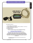
USER MANUAL RS485 4 PORT HUB
C3BUS
INCLUDED IN THIS KIT:
1.
2.
3.
4.
5.
USB to RS485 4 Port Hub Module
Universal WallPlug Power Supply. 100VAC to 240VAC in ; 5V DC out
USB A to USB B interface fable (6ft )
Installer/driver CD **
User Manual (PDF) **
** May be on Master Support CD in RS-485Hub4 Folder
Version 1.0 DATE: 10/30/2012
See www.CandCNC.com/Manuals.htm for updates
Copyright notics: All content is protected by copyright
Any reuse or reproduction in whole or part witout permission
is prohibited. Any user manual may be reprinted in part or whole by
the owner of the products covered by the manual for their own
private use.
Any trademark or logo used in this manual is the property of the
the trademark owner
CandCNC
Page: 13
USB- RS485 4 PORT HUB
Plug Locations and Layout
C3BUS USB to RS485 4 PORT HUB
Handles all secondary (backside) communications too and from
the DTHC IV to MACH3. All screen readouts and all settings to
the DTHC IV are handle by the C3BUS. The HUB UTILITY
uses the same C3BUS to communicate with all the RS485
modules including the DTHC IV. It is essential the C3BUS be
installed and running BEFORE you attempt to setup the
RS485 4 PORT HUB (TOP VIEW)
PWR
Con ACT
USB
RS485 4 PORT HUB
(END VIEW)
RS485 4 PORT HUB (FRONT VIEW)
CandCNC
Page: 14
USER MANUAL RS485 4 PORT HUB
Universal AC power Plug
100VAC to 240VAC 50/60HZ
Regulated 5V @ 1A out
PWR
USB ACT LED shows
Valid connection to PC
on USB channel
Con ACT
USB
To EPO on ESP front panel
or EPO on Table I/O
ACTIVITY MONITOR
LEDS
When a device is plugged
into a port on the hub the
LED will light if it has
proper communications. It
does not mean the device
is operating correctly (see
later pages for using the
Hub Utility). The Activity
Monitor shows
Standard CAT5 UTP up to 50ft
ARC
OK
Z
ON
SENSOR INPUT
DTHC
Steps
RESET
HOLD
To PWM Module
CandCNC
Electronic Controls for CNC
DTHC IV Digital Torch Height
To HUB
RS485
Port1 INPUT
C3BUS
CP PWR UBOB III™ Technology
To PC
CandCNC DTHC IV (parallel port) system shown
CandCNC
Page: 15
CONNECTION EXAMPLES
The CandCNC C3BUS ™
USB to RS485 4 Port Hub
C3BUS™
RS485 4
Port Hub
CONTROLLER
PC
Mount close to PC
USB
6ft max
CAT
CAT5
5
up to 50
ft
up
CA
T5
to
t
f
50
PN200
DTHC IV
Mark IV
CAT5
HYPERTHERM
65/85/105
with RS485 Port
EZPlug II
SERVO
CandCNC
CandCNC
RS485
Cards
up to 50ft
CAT5
UBOB
Mark IV
48 function
Hand Controller
Relay
4X4 Driver
card
Relay
4X4 Driver
card
CandCNC
RS485
Cards
Spindle
SSpeed
Mark IV
NOTE: Example ONLY some of
the examples are not available
yet. Only ones in Yellow are
currently available. Names may
change and release dates are
not yet scheduled
Page: 16
4. Plug the USB-RS485 4 Port Hub wall plug power supply into an AC outlet
NOTE: While the wall plug power supply has pins for standard US AC
120VAC sockets the power supply will work and run from any AC power
source from 100 to 240VAC 50/60HZ. You can purchase plug adapters from
several on-line merchants including Amazon ,com for less than $2.00
No voltage conversion is necessary.
5. . Using the included USB A to B adapter cable plug the B plug into the
matching jack at the end of the hub and the other end into any open USB jack
on the control PC,
Note: for testing you can load the drivers and CandCNC Hub Utility on
any PC or Laptop. . but for operation you need to have the hub installed and
working in the PC that runs MACH and controls you machine
6.. Windows will see the new hardware and will launch the Hardware Install
Wizard. Use the following screens to finish the hardware install
First Screen of
Hardware
Install(Update)
Wizard.
Leave the radio
button set on the
“No, Not this time”
option and hit the
Next Button....
CandCNC
Page: 17
INSTALL
RS485 4 PORT HUB - HARDWARE
INSTALL
INSTALL
RS485 4 PORT HUB - HARDWARE
INSTALL
Next Screen of
Hardware
Install(Update)
Wizard.
Leave the radio button
set on the
“Install the software
automatically”
option and hit the
Next Button....the
driver has already
been installed in the
earlier steps so you do
This completes the
software and driver
install for the
CandCNC USB to
RS485 4 port Hub.
See the following
pages for checking
the install and to
use the CandCNC
Hub Utility (Admin
CandCNC
Page: 18
INSTALL
RS485 4 PORT HUB - HARDWARE
INSTALL
7. To confirm that your USB-RS485 4 PORT HUB drivers have been installed, open the
System Application in Control Panel and then the Hardware Tab and the Device
Manager. You will see a “Tree Structure” of hardware devices. Scroll to the bottom and
Find the UNIVERSAL SERIAL BUS DEVICES and under it you should see the
CandCNC USB to RS485 hub device. IF YOU DO NOT then unplug the USB
connector (either end ) and wait 5 sec and plug it back in. You should NOT get the
Hardware Install or Update Wizard . The Device manager should update and show you
the screen below.The CandCNC USB to RS485 hub device will only show up when it is
plugged in
CandCNC
Page: 19
The USB Active (ACT) LED only comes on
when there is a valid USB connection to the
PC. Drivers have to be loaded and active.
USB ACTIVE LED
PWR
Con ACT
USB B plug to PC
USB
INSTALLING CandCNC RS485 Devices to the USB-RS485 4 PORT HUB
The USB-RS485 4 PORT HUB has an advanced processor than can communicate
with several RS485 devices. RS485 is a robust and noise-immune communications
standard used in industrial electronics for years. Because of its differential signal
methods it is unaffected by external or ground based noise and reliable
communications of several hundred feet are common. RS485 is a multi-drop
topology meaning there can be multiple devices on the same pair of wires as long as
all of the devices operate at the same speed (BAUD RATE) and have a unique
address. Since USB is a common port on most PC’s it is a logical choice for
communications that do not depend on precise timing.
You will note that the USB-RS485 4 Port Hub has four in dependant channels ad
each channel can talk to multiple devices, Because of different Baud Rates or
special signals the 4 port hub has two special jacks:
1. Hypertherm RS485 Port. This channel runs at a much slower speed and can
only talk to a Hypertherm Plasma Cutter equipped with an RS485 port (optional) and
through our HyT-Connect RS485 interface. If you already have the HyT-Connect
RS485 SIM Kit installed and have the older single port (dual jacks) RS485 module
you need to unplug the existing setup and plug the RJ45 (Cat5) cable FROM the port
on the rear of the Hypertherm into the jack 1 marked “To Hypertherm Rs485 PORT
CandCNC
Page: 20
INSTALL
RS485 4 PORT HUB - DEVICE CONNECT
TAP
INSTALL
USER MANUAL RS485 4 PORT HUB
Plugging RS485 Hypertherm into RS485 PORT on back of
Hypertherm 65/85/105
See HyT-Connect Manual for details on installing and
using the RS485 remote control for the Hypertherm
and the DCC (Dynamic Cut Control)
CandCNC
Page: 21
USER MANUAL RS485 4 PORT HUB
2. PN200 Hand Control. The PN200 hand control uses normal high speed baud
rates but the special “dead man” E-Stop to the EPO of any CandCNC controller
requires a special jack. The PN200 MUST be plugged into the PN200 jack to be able
to use the E-STOP safety (recommended). The PN200 has to be the last device in a
group of devices. The PN200 will worked plugged inot other jacks on the 4 PORT
HUB (except JACK 1) but you cannot use the E-STOP option. You can also use the
PN200 jack on the hub for other RS 485 devices if you do not have a PN200. While
the PN200 would work with other devices on the channel that have loop through (pass
through) jacks the E-STOP to EPO DOES NOT PASS THROUGH OTHER DEVICES
3. DTHC IV High Speed Digital Torch Height Control. The DTHC IV uses the
RS485 (C3BUS) for the following :
, Transfer of screen information TO MACH3 like Torch Volts, Torch Amps and the
status LED’s for Torch UP Torch DOWN and ARC OKAY. Unlike the DTHCII that uses
defined parallel port inputs for the UP, DOWN and ARC OK, the DTHC IV sends the
data across the RS485. The only “hard” input from the DTHCIV to MACH3 is the
HOLD signal (mapped to INPUT 1 on Ports & Pins)
, Communication to the plug-in in MACH3 to update Z position when DTHC is
active(tells MACH3 where the DTHC has moved the Z while under THC mode)
, Pass parameters and settings in MACH to the memory of the DTHC IV. This
includes all of the DTHC Cut Profile Settings either from the screen or from the Gcode when using DCC
C3BUS MANAGING THE HUB
During the install the CandCNC Hub Utility was
added and an ICON was placed on your desktop.
Click on th icon to open the Hub Utility.
IMPORTANT: The purpose of the HUB UTILITY is primarily to confirm proper
communication with each device and to be able to do some base level testing . You
cannot run the Hub Utility at the same time as MACH is running
The following screens show the CandCNC Hub Utility displaying information about different
devices connected to it. The Hub is “smart” and automatically detects any compatible device
connected to it. Review the screens that follow and understand what each section of the
screen is used for.
CandCNC
Page: 22
DEVICE DETAILS
Provides the:
Device Name
Device Code: Each
CLASS (type) of device
has a different Device
CODE Codes can be from
1 to 99.
Device Address: The
unique address of a device
within a class (values from
1 to 8).. Devices of the
same type must have a
different Device Address.
Future cards will have
address jumpers to allow
multiple cards of the same
type to work on the same
hub.
Firmware Version: This
displays the current
DEVICES:
Shows a list of
connected
devices. As a
device is
connected and
sensed by the
hub it will appear
in the list. If you
connect a device
and it does not
show up
immediately,
stop (close) the
application and
restart.
Hub Connected
(to USB on PC)
Displays current
firmware of the HUB.
This MUST show
connected status
before any other of the
functions will display
TEST DEVICE
Action button that
opens a new
dialog window.
You must have a
device
highlighted in the
Devices List to
Update Device Firmware.
This allows you to update
each module with new
firmware. New firmware
will be designated by a
REV number. Firmware
updates will be available
for down load in a special
download section of the
CandCNC website and on
the Yahoo
CandCNCSupport Forum.
The Hub Utility is an application provided to manage the C3BUS USB to Rs485
4 Port Hub and the devices attached to it. With the utility you can:
Updte the Hub Firmware (Firmware is the program that runs the hub)
Update Firmware in the Devises attached (like the DTHCIV)
Test basic communications
Test device functions
Device level diagnostics
Set some device settings
What you CANNOT DO:
Run MACH3 (Both applications trying to talk to the same device does not work)
CandCNC
Page: 23
C3BUS HUB
C3 HUB MANAGEMENT
HUB UTILITY
DTHC INFORMATION is direct feedback from the DTHC IV module and indicates the
current status of the unit . You cannot make changes or do inputs from this section.
Since you cannot run MACH and the Hub Utility at the same time these settings are
primarily used for off-line diagnostics at the factory
Z MOTOR SETTINGS. This section is the most important because it sets the base motor
settings for the Z motor under DTHC control. You will find that the Max Velocity and
Acceleration will be much higher than your settings in MACH for the Z motor tuning. This is
normal because of the DTHC IV controlling the motion directly under THC. You should set this
as high as possible. Move the settings up and test the Z motion using the Full Speed Jog
buttons on the screen. The motor should move smoothly and rapidly both up and down. Lose
steps (or faults on a servo system) back the numbers off by 25%. The settings here are for a
stepper system with a 620 oz-in motor running a 5 TPI leadscrew. You settings will vary but
you should be able to hit about double the velocity and acceleration of the Z motor tuning in
MACH. IT IS IMPORTANT THAT THESE SETTINGS BE OPTIMIZED for best response under
DTHC control. They will effect the Gain and Tracking settings for the DTHC
THIS IS THE ONLY PLACE TO SET THE Z TUNING FOR DTHC IV . A MINUMUM INSTALL
REQUIRES YOU PREFORM THIS ONE FUNCTION IN THE HUB UTILITY
DTHC SETTINGS . These are the same as using the CUT PROFILE when MACH is running and serve
to be able to test the RS485 communication to / from the DTHC IV and to test the DTHC IV memory and
interface. In normal cutting these settings are provided by the Cut Profile and/or the DCC values from the
G-Code at run-time. The Cut Profile in MACH now allows multiple levels of settings and is a better place to
do the setup and testing under MACH.
CandCNC
Page: 24
C3BUS HUB
HUB MANAGMENT
HUB UTILITY
C3BUS HUB
HUB MANAGMENT
HUB UTILITY
MISC:
Opens choice to
update firmware
This is the first
step in updating
the HUB
FIRMWARE
Current Firmware Version
Select the highest release number
new firmware can be found on the
Candcnc website (manuals page)
CandCNC
Page: 25
HUB MANAGMENT
HUB UTILITY
To update the USB-RS485 Hub Firmware you must:
1. Download a designated file from the CandCNC Website (Product Support Tab) and
place it in a named folder on the machine that has the hub attached. Select the MISC tab
at the top and you will have an Update Hub Firmware choice (other choices for other
functions may be added later)
2 Click on the Update Hub Firmware and a File Navigation window will open and you can
navigate to the file in the folder you have downloaded the new firmware to. The file
extension for all Firmware updates will be ucccx. Highlight the file to use and hit the
OPEN button. The Hub Utility will automatically update the hub firmware.
CandCNC
Page: 26
DEVICE TESTING: PN200 48 Function Hand Control
IF YOU DO NOT HAVE THE PN200 the device will not show up
in your devices list and this screen will not appear
Joystick shows XY
positionwhen stick
on the PN200 is
deflected. Confirms
operation or Joystick
L 1 - L5 (lamps)
are indicators. You can
clcik on the L numbers
to turn on an indicator
on the PN200 to test.
Checking the box under
it will cause it to flash.
Multicolor LEDS will
change colors if you
click the L button again.
LED Fast Flash changes
ROTARY ENCODER
TEST
Enc1 (DTHC
PRESET) encoder
status. Rotating the
encoder will increase
the count clockwise
and decrease counter
clockwise.
Enc2 (FeedRate)
Does the same.
5 X 5 keypad
reflects button pushes on the PN200
keyboard and displasy key number in the
Last Key DRO
CandCNC
IF YOU DO NOT HAVE THE HyTConnect RS485 options the device will
not show up in your devices list and this
screen will not appear
Page: 27
C3BUS HUB
HUB MANAGMENT
HUB UTILITY
Setting Up EtherCut Systems with Ethernet and IP Address
CandCNC
Page: 28
INSTALL
MACH SCREENS FOR DTHC IV & ETHERCUT
DTHC IV Screen Set with DCC/TAP flyout using TAB key
NOTE: Screens change as we upgrade certain features and your screen may not look
exactly like this one but it should be similar.
CandCNC
Page: 29
DTHC IV + Ether-Cut Screen Set with DCC/TAP fly-out using TAB key
SETTING UP THE ETHERNET PORT
FOR ETHER-CUT
CandCNC
ETHER-CUT
INSTALL
(Windows XP)
Page: 30
ETHER-CUT
INSTALL
SETTING UP THE ETHERNET PORT
FOR ETHER-CUT (WIN XP)
Make sure the Network Adapter
does not show disabled or notworking warning symbol!
This does not mean the
Device is actually “working”
and will talk to a network or
the Ether-Cut. It simply
means Windows sees the
device and it appears the
right drivers are loaded. If
you have problems
configuring or testing the
port it can still be a bad
Ethernet card or the wrong
card drivers
CandCNC
Page: 31
NOTE the screens shown
are for an NVIDIA Network
card and may have
different option scrrens
andsettings. Most cards
have default settings that
are correct and do not need
to be changed.
When running MACH3
on a computer you
MUST turnoff all Power
Saving options in
Windows and make sure
the communications
device is not set to turn
off to save power. This
option may not appear
on all Ethernet Cards
CandCNC
Page: 32
ETHER-CUT
INSTALL
SETTING UP THE ETHERNET PORT
FOR ETHER-CUT (WIN XP)
ETHER-CUT
INSTALL
SETTING UP THE ETHERNET PORT
FOR ETHER-CUT (WIN XP)
Make sure the Local
Area Connector does
not show it is
disabled. It may
show it is not
CONNECTED but if it
is missing or disabled
you will need to get
the problem resolved
before you can
proceed with the
install
CandCNC
Page: 33
Find the Local Area
network (there may be
wireless networks
shown too). Ether-Cut
needs a DEDICATED
network connection
from the ehternet port
on the pc directly to the
EtherCut connector
ETHER-CUT
INSTALL
SETTING UP THE ETHERNET PORT
FOR ETHER-CUT (WIN XP)
Right click and select
PROPERTIES from the
List Box. The
Properties window will
display.
Scroll to the
Internet
Protocol device
and hit the
PROPERTIES
button
CandCNC
Page: 34
The TCP/IP Properties
window will appear.
Make the following changes:
Select “Use the following IP
Address”
Type in the IP address
exactly as shown (10.9.9.1)
Type in the Subnet mask
exactly as
shown(255.255.255.0)
Do not assign a Default
Gateway (blank)
Do not assign any DNS
servers (blank)
Do not use the Advanced
button.
A NOTE ABOUT THE TCP/IP Address and the Ether-Cut
The Ether-Cut uses a modified version of the ESS Smooth Stepper™ and the manual
for that product should NOT be used for this installation. We have all of the settings
(including the IP address of the ESS card) preset and tested at the factory as part of
the final system tests we do on all our products. The address of the ESS is 10.9.9.9.
It is STRONGLY advisable that you DO NOT run this through a hub or have it on a
network with other devices. If you need network or wireless connectivity you need to
install another device and set that up separately with it’s own address and settings.
You can run multiple Ethernet cards in the same computer. For the Ether-Cut setup,
there is NOTHING you need to change or setup other than the Ethernet port on your
control PC. If you cannot get the proper indications or the ping response on the tests
and have done all of the CandCNC Ether-Cut installation, than it is most likely a PC
related Hardware problem. A lot of PC’s (Dells in particular ) from refurbishers or that
have been used with the parallel port version, may have the Ethernet disabled or the
proper drivers not loaded. We have found that if you load the wrong driver you may
get an indication in the Device Manager the Ethernet card is OK but it still won’t
communicate. Windows does no testing for functionality of ANY device. It just
confirms it is there. If you cannot get your Ethernet port to function properly than you
should check and see if there are driver updates for your PC and the Ethernet Card
you have.
CandCNC
Page: 35
ETHER-CUT
INSTALL
SETTING UP THE ETHERNET PORT
FOR ETHER-CUT (WIN XP)
The procedure for setting up the Ethenet address and settings on Windows 7 for the EtherCut are very simialr to those for Windows XP show in the previous pages . The process of
getting to the Network Connections is a little different
A NOTE ABOUT USING WIN 7 with MACH3. You must use a 32 bit version of Windows 7
to run MACH3 and the Ether-Cut. You cannot use WIN 7 64 bit running in 32 bit emulation.
Select Control Panel
from Start Menu
Select Network and
Sharing Center from the
Control Panel Full
Menu
You will get a graphical
representation of your
network and installed
links.
On the left you will see
the Change Adapter
Settings menu choice
Make sure the Local Area
Connector does not show it is
disabled. It may show it si
not CONNECTED but if it is
missing or diabled you will
need to get the problem
resoved before you can
proceed with the install
CandCNC
Right click and select
Properties
Page: 36
ETHER-CUT
INSTALL
SETTING UP THE ETHERNET PORT
FOR ETHER-CUT (WIN 7)
ETHER-CUT
INSTALL
SETTING UP THE ETHERNET PORT
FOR ETHER-CUT (WIN 7)
Highlight Internet
Protocol Version 4
(TCP/IPv4)
Click Properties
Button
Select Use the
Following Address
Enter the address
exactly as shown
10.9.9.1
Enter the Subnet
Mask exactly as
shown
255.255.255.0
Leave all other
settings blank
(no DNS servers)
Click OK to save
CandCNC
Page: 37
2
TO
UP
To PWM
Module
5ft
ETHER CUT Connections Guide
ARC
Z
ON
OK
Status
DTHC
SENSOR INPUT
CandCNC
DTHC IV Digital Torch Height
Status
Steps
RESET
HOLD
To PWM Module
To PC
Ethernet
Electronic Controls for CNC
ETHER-CUT
To HUB
CP PWR UBOB III™ Technology
UP TO 25ft
RS485
C3BUS
BLUE CAT5 cable
for
RS485 from
C3BUS Jack on
Ether-Cut to
Green Cat5 from Ethernet
Jack on Ether-Cut front
panel TO Ethernet jack on
PC. Up to 25ft length.
UP TO 25ft
Ethernet Jack
CAUTION: All cables are CAT5
UTP 8 conductor and will plug into
any CAT 5 (RJ45) jack. We have color
coded the cables to help keep them
from being mis-connected. If you
use other CAT cables be sure to label
them on each end. Connecting cables
wrong could damage modules.
CandCNC C3BUS RS485 4 Port Hub
PWR
Con ACT
USB PORTS
USB
6
ft
or
le
ss
HUB is REQUIRED
for DTHC IV
CONTROLLER PC
RUNNING MACH3
CandCNC
Page: 38
ETHER-CUT
INSTALL
CABLE CONNECTIONS for
DTHC IV , C3 BUS & ETHER-CUT
OPTIONAL TESTING OF THE ETHERNET PORT
TESTING Your IP address:
To do this test you must have the Ether-Cut connected to the Ethernet jack
on the PC. You should see the yellow LED on the JACK (RJ45) of the Ether
cut come on steady as soon as the two are plugged in together and both
powered up. This LED indicates there is a physical connection ( the cable is
good and both ends are connected and have power) it DOES NOT indicate
the two are actually talking (sending data). The Green LED does indicate
activity (both send and receive ) so it may confirm there are packets going
one way it does not indicate
CandCNC
Page: 39
ETHER-CUT
INSTALL
SETTING UP THE ETHERNET PORT
FOR ETHER-CUT
SETTING UP THE ETHERNET PORT
FOR ETHER-CUT
When you open the Ether-Cut Profile for the first time you should see the
dialog box above. MACH should recognize the ESS Ethernet device and
ask you if you want to use it instead of the Parallel Port (You DO!)
If you DO NOT see the dialog box and MACH opens than it may have
already been set. If the ESS fails to load and you cannot get the screens
in the Plug-in Control menu than use the top menu bar and the
Functions Cfg’s menu and select the Reset Device Set..option. Stop and
restart MACH. If you get an error message like
MACH does not see the ESS Ethernet Device and you need to go back
through the IP setup and the tests to make sure the card is communicating
with the PC Ehternet port
CandCNC
Page: 40
modules setup
dthciv mODULE
pwm module
rav-O1 vOLTAGE dIVIDER (option)
THE FOLLOWING SECTIONS DEAL WITH SETTING UP EACH MODULE.
IF YOU HAVE A CandCNC Product you may not need to use one or more
of these sections since some products have theses modules already
installed, tested and calibrated.
IF you have a BLADERUNNER AIO Dragon -Cut or any MP3000-DTHCII
based product (Plazpaks) than YOU CAN SKIP THE SECTION ON
INSTALLING AND SETTING UP THE DTHCIV Module,
YOU DO NOT NEED TO ADJUST or Calibrate a DTHCIV From the
factory. All units are calibrated prior to shipping
CandCNC
Page: 41
INSTALL
DTHC IV
Digital Torch Height DTHC IV Module
DTHC IV
The following section goes through the initial setup and checking of
the DTHC IV. The procedure is somewhat different than the previous
DTHC and DTHC II and if you are upgrading from those platforms
please take the time to go through this section. The end results will be
more satisfactory tha just plugging everything in and trying to cut a file
CandCNC
Page: 42
DTHCIV MODULE
above the UBOB III card in most CandCNC
products.. Ribbon cable connecting DTHC
16 pin header (plug)
down to UBOB card may cover adjustment
for DTHC to UBOB
pots. If so, gently move it out out the way. Do
Cable
not unplug the ribbon cable or the card will be
disabled.
BladeRunners and MP3100-DTHCIV
Units have this module already
installed and IT IS CALIBRATED. DO
NOT ADJUST POTS
Four wide cable is
for UBOB cards
prior to REV 15
Set JP4 and JP5 ON
(jumpered) for REV15
UBOB . OFF for
earlier versions
TORCH VOLTS Calibration
SET FOR 126-128VDC
INDICATED [TORCH
VOLTS] Unit is calibrated
at the factory.
DCP Calibration
POT Factory set
for 100A test
FRONT PANEL
RS485 JACK
RESET
Yellow TORCH ON
on when Torch fire
signal is active
Green Power LED
Should be ON
RJ45 connector for CAT5
cable to PWM Module
Steps
DTHC
ARC
Z
ON
OK
RESET
HOLD
To PWM Module
SENSOR INPUT
DTHC IV Digital Torch Height
CandCNC
Page: 43
INSTALL
DTHC IV
DTHC IV EXPANSION MODULE. Located
PRELIMINARY TESTING THE DTHC MODULE:
The only preliminary tests of the DTHC IV module are for power getting to the board and to
test the RESET button and check for the initializations sequence on the front panel LED’s
1. Power up the Bladerunner/MP3000/MP3100/Plazpak and watch the front LED’s on the
DTHC IV. They should turn on one at a time from right to left starting with the ARC OK LED,
then all LEDS should flash twice. This indicates the microprocessor in the DTHC IV is alive
and working.
2. An integral part of the DTHC IV communications too and from MACH are dependant on
the C3Bus USB to RS485 4 port Hub. A lot of testing and DTHCIV settings are done via the
HUB UTILITY through the C3BUS. They will be covered later after the other components
and cards have been installed and tested
Front Panel Indicator Identification
Steps
DTHC
ARC
Z
ON
OK
RESET
HOLD
To PWM Module
SENSOR INPUT
DTHC IV Digital Torch Height
SIGNAL
NAME
ARC OK
COLOR
YEL
DTHC ON
BLU
STEPS Z
RED
FUNCTION (What it means)
Shows the torch is on and that
there is a valid arc so automated
Cutting can begin. Signal comes
from Plasma (PWM Module) or from
DCP-01 current reading
The DTHC can be turned on and
off in software and from the screen
it shows when the DTHC is active
Shows Z motion activity from both
DTHC and MACH control
RESET button resets the DTHCIV
RESET
Button processor and does an initilization
Pattern for self check
Indicates the DTHCIV has issued
a HOLD command back to MACH
to prevent motion
HOLD
RED
RJ45 RT
GRN
DTHCIV POWER INDICATOR
On all of the time
RJ45 LFT
YEL
TORCH ON. Shows torch FIRE
signal from MACH3
CandCNC
Page: 44
INSTALL
DTHC IV
DTHCIV MODULE
CUT PROFILES
How to access the CUT PROFILES (Stored Settings) in
MACH.
Use the TAB key on your keyboard and the “Flyout” screen will
pop upon the right side of your normal Program Run Screen.
You canslide the separator bar over to uncover the Program
run screen if you wan tot have both open at the same time.
NOTE: It is best to run your video screen resolution at 1280 X
1024 or higher so the program run screen does not take up all
of the monitor and you have some room left for the flyout.
Most video drivers and monitors will handle 1280 X 1024 and
later ones have other resolutions higher. The MACH screens
we supply are 1024 X 768. The higher the resolution you run in
windows the smaller portion of the monitor the MACH scrren
takes up. Set your system up to your preference with the tab
flyout in mind. Most of the settings on the tab flyout are not
done while you are cutting
To access the following setting
screens you have to click on the
CUT PROFILES Button (located
on the tab flyout on most screen
sets.
WARNING: If you do not have the C3BUS Hub setup and working
and the DTHC IV shows up in the device list, THIS BUTTON DOES
NOTHING! Without communication between MACH and the
DTHC IV you cannot read or change settings
NOTE: DTHCII and older screen sets only have one level
of tabs to select ,edit and choose a CUT PROFILE. Your
old CUT PROFILES from earlier installs will still be there
but now you have additional tabs and settings available.
This is an important thing to note in the DTHC IV setup and
interface.
CandCNC
Page: 45
INSTALL
DTHC IV
DTHC IV MACH3 CUT SETTINGS TAB
This is the opening TAB of the CUT PROFILE MENU. The DTHCII version of this
screen only has one level and is used to set the DTHC parameters for a cut. There are
STORED SETTINGS and they are listed in the Current DTHC Settings window. The
DTHC cut values can be changed on the screen and Save applies them to the DTHC
memory. You can add new profiles with different presets.
NOTE: The DCC function provided by using SheetCAM TNG and the POSTS that
support DCC WILL OVERRIDE THESE SETTINGS when the G-Code is loaded and
the RUN button is hit. The operator can choose to override the base settings via the
screen (Preset Volts, DTHC Delay, etc) OR override the entire profile by opening the
CUT PROFILE and hitting SAVE after the G-code has stopped on the tool. CAUTION:
The code stops on each tool used and the settings are updated. The last set of
parameters to be loaded to the DTHC memory will be the one used during the cut
CandCNC
Page: 46
INSTALL
DTHC IV
DTHC IV MACH3 CONTROL
DTHC SETTINGS TAB
DTHC SETTINGS TAB opens up a screen with 3 sections. Each one has specific functions that
will be covered in the following pages. The DTHC Settings effect the Operation of the DTHC IV
and are global and not by Cut Profile (previous TAB). These settings remain in effect until they
are changed in this menu.
CandCNC
Page: 47
INSTALL
DTHC IV
DTHC IV MACH3 CONTROL
DTHC SETTINGS TAB
SELECTING DTHC RESPONSE PRESETS
There are six DTHC Response presets for different types of cutting conditions. There are
three for Stepper and Three for Servo based Z axis.
Slow Preset: Is for general flat sheet cutting of material that does not tend to warp more than
about a ½”rise over 2 inches or more of length. Slow does not mean the motion is slow but
rather it slows down the response to voltage change during a cut and dampens over-response
to brief spikes or dips in arc gap (arc volts)
Medium Preset: Is for cutting thinner material that can warp more intensely and allows
respones to cut up to about a 30deg rise at rates up to about 200 IPM XY rates* Select this
Preset if you cut 16ga and thinner and you see a lot of warping and vertical changes.
Fast Preset: Is for very aggressive cutting on severe warps, corrugated or at very high cut
rates. This setting will function to cut up to a 45 deg slope at 180 IPM and smaller slopes at
350 IPM*. It will cut thin corrugated (some other DTHC settings may need to be adjusted )
Stepper setting VS Servo setting. Servos present different dynamics and tuning issues
than steppers. They typically have much faster top velocity rates and a wider range of torque.
Only slect this mode is your Z is a servo motor
* It is important to understand that the above settings and suggestions are based on typical
leadscrew type Z mechanisms with average pitch of .2 “ (5 mm) for stepper and .1 “ (2.54
mm) for servo
The settings may need to be adjusted for courser or finer pitches. Use the CUSTOM setting
if the presets do not product smooth response.
CandCNC
Page: 48
INSTALL
DTHC IV
DTHC IV MACH3 CONTROL
DTHC SETTINGS TAB
SETTING DTHC RESPONSE USING CUSTOM Settings
If you select CUSTOM in the Preset Tuning buttons the DTHC Sensitivivy and DTHC
Tracking will no longer be grayed out and can be used to custom tune the Z for a given
condition. You may find that custom tuning is needed if your Z mechanics are either very
course or very fine.
DTHC Sensitivity determines the response RATE (how quickly the Z responds to small
changes in the ARC VOLTS). Setting the DTHC Sensitivity higher will force the DTHC IV
and the Z to increase the rate that it responds.
DTHC Tracking determines how close to the PRESET VOLTS the DTHCII will try and hold
the changes (dampening). The resolution of the DTHC IV is 1/16 VDC. It uses a unique nonlinear averaging algorithm developed specifically for Torch Height Control Typically the two
settings are interactive. If you increase one you may need to decrease the other or vice
versa. Too much DTHC Tracking will cause Z oscillation (the Z will move up and down
rapidly as it cuts) . Zero tracking is a valid setting in some circumstances. When making
changes to either setting does so in small increments. Once you have a good setting
make note (write it down) for both values. .Over time we will develop numbers for different
configurations of Z mechanics and motors and make them available in a chart.
Slowest Velocity (Default value = 10) is the slowest speed in IPM that Z will travel while
under DTHC control. It the DTHC moves based on an error voltage this is the MINIMUM
speed it can move at. (it moves faster the greater the error) It effects the lower end of the
response curve to give better response to small amounts of change.
Voltage Tracking Tolerance. This is the voltage range that the DTHC works across from
minimum to maximum velocity. It is the allowable error. This works in combination with the
DTHC tracking value to establish the response curve of the DTHC. The value is in VOLTS
of error and the default 1 volt setting is appropriates for most applications.
CandCNC
Page: 49
OTHER DTHC SETTINGS. Located in the Center of the DTHC SETTINGS TAB
the 4 input boxes allow for changes in the Voltage Fault (Volts out of range error
code trigger) and two inputs for use if the DCP-01 is being used. (NOTE the
ARC OK CURRENT needs to be set to some value above 0 of it will false trigger
on system that DO NOT use the DCP-01 )
Upper Volts Fault Limit: Set this value to about 10% below the open circuit voltage
of your plasma torch (voltage when fired in the air) It will prevent DTHC signals from
moving the torch too far down in the event the torch runs off the material or hits a
void.
Lower Volts Fault Limit: Set this value to a number that triggers a fault if the voltage
is below the normal cutting voltage of the torch with the consumables you use.
If you change consumables that have different settings you may need to adjust the
parameters or you can set the lower limit to reflect the lowest voltage used with ANY
type consumable.
Arc OK Current: This setting is used when the plasma unit you are using DOES
NOT HAVE an ARC OK (OK to MOVE; Arc Xfr; TRANSFER, Etc) signal. The
UNIVERSAL CONNECTION KIT from CandCNC has the DCP-01 Digital Current
Probe that reads Arc Current (amps) flowing in the Workclamp lead and is used to
trigger the ARC OK signal. If you have the DCP-01 connected and in use either in the
Universal Connection Kit or as part of the TAP (Advanced Interface Kit) you should
set the Arc OK value to about ½ of the lowest cut current you use. It is important to
understand that the ARC OK can be triggered by EITHER the hard signal reading
currfrom the plasma or from the DCP-01 reading current greater than the Arc OK
Current setting.
Current Tolerance: This setting is a percentage of the indicated Cut Current and
works in conjunction with the ARC OK CURRENT and has to have the DCP-01 to
monitor the actual cut current. It triggers a current fault and there are General
Options that control what happens if a current fault I uses the PRESET CURRENT
CandCNC
Page: 50
INSTALL
DTHC IV
DTHC IV MACH3 CONTROL
DTHC SETTINGS TAB
INSTALL
DTHC IV
DTHC IV MACH3 CONTROL
DTHC SETTINGS TAB
General Settings are options to do specific functions in the event of a Fault. Faults
come from two sources: Voltage outside the range of the Upper Volts Fault Limit or the
Lower Volts Fault Limit OR if you are running with a DCP-01 module and have actual
cut current readout and parameters set for Arc OK Current and Current Tolerance,
Current that falls outside the parameters you have set.
Stop on Fault. Stops motion in MACH if there is a VOLTAGE fault
Raise Head on Fault Does a quick retract of the Z up to Safe Height on a VOLTAGE
fault
Stop on Current Fault Stops motion in MACH if there is a CURRENT FAULT
Torch Off on Arc Loss. This turns off the OUTPUT in MACH that fires the torch.
Most torches will turn off If they lose arc (typically they lose arc because they have
turned off) but the OUTPUT will stay on in MACH
DEFAULT SETTINGS: All boxes unchecked (off). It is recommended that you leave
them unchecked until you have the system setup and cutting well. Only turn any one
of there if there is a specific problem that needs to be fixed. The cause of a the fault is
more important to resolve than what happens after. If you have faults while cutting
there is usually a reason and it needs to be investigated and fixed.
CandCNC
Page: 51
This screen is INFORMATIONAL ONLY. You must set the DTHC Motor
Parameters in the HUB UTILITY. The values shown may not be the ones
your system uses.
END OF DTHC IV MODULE INSTALL
CandCNC
Page: 52
INSTALL
DTHC IV
DTHC IV HUB C3BUS CONTROL
DTHC Motor Tuning
SETTING UP THE THC SENSOR PWM MODULE
IF you already have a working PWM Module with your DTHC II
. upgrading to the DTHC IV
of either REV number and you are just
you can skip this section of the setup
THC SENSOR
PWM REV 17
(Mod A) to REV
20
PWM MODULE
REV 21 and later
The THC SENSOR PWM MODULE (PWM Module) has been
redesigned to fit into a smaller case. The function and settings are
EXACTLY THE SAME. If you have a working REV 20 or sooner module
your DO NOT need to upgrade it to a newer REV 21. This manual is
written for using either module and the setup and testing is the same .
Certain indicators and button locations have been moved
CandCNC
Page: 53
INSTALL
PWM MODULE
THC SENSOR PWM MODULE
THIS MUST BE DONE TO MATCH YOUR INSTALL
UNITS ARE SHIPPED TO MATCH THE RAV-01 (7:1)
RATIO. USE THE CHART BELOW IF YOU ARE USING
THE MODULE WITH A PLASMA WITH AN INTERNAL
VOLTAGE DIVIDER. SEE THE SECTION ON
CONNECTING A PLASMA WITH AN INTERNAL
VOLTAGE DIVIDER TO DETERMINE TE PROPER RATIO
To set THC SENSOR PWM ratio divider option:
1. Remove rear cover of THC SENSOR PWM Case
2. determine the proper setting for the type setup you have.
3. Set the small option jumper to match.
41C
VOLTS
TEST
OLDER MODEL
REV 17 - REV 20
Shown.
+
YALER HCROT
3RV
1D
WAR
STLOV
LAC
Volts
SCALE
1K
20:1
SWERCS
16:1
7:1
1
AMSALP OT
ARC OK
TEST
50:1 = No jumper
2J
Volts
SCALE
20:1
16:1
7:1
20:1 Scale (Hypertherm and
some others)
Volts
SCALE
20:1
16:1
7:1
Volts
SCALE
20:1
16:1
7:1
16:1 Standard on
Thermal Dynamics, others
7:1 Divider
(from CandCNC RAV-01
Card )
Volts
SCALE
Volts
SCALE
20:1
20:1
16:1
16:1
7:1
7:1
or
CandCNC
50:1 Standard on
Hypertherm,
Thermal Dyamics, others
Back of THC SENSOR PWM
Cover removed
IMPORTANT:
The Hypertherm 45 has an
internal voltage divider. It
cannot be changed for the
50:1 ratio. Set your THC
SENSOR PWM jumper to
the 50:1 position if you are
using the MIC-01 Direct
Connect Cable
Page: 54
INSTALL
PWM MODULE
SETTING THE THC SENSOR PWM PRESCALE
DIVIDER RATIO
THIS MUST BE DONE TO MATCH YOUR INSTALL
UNITS ARE SHIPPED TO MATCH THE RAV-01 (7:1)
RATIO. USE THE CHART BELOW IF YOU ARE USING
THE MODULE WITH A PLASMA WITH AN INTERNAL
VOLTAGE DIVIDER. SEE THE SECTION ON
CONNECTING A PLASMA WITH AN INTERNAL
VOLTAGE DIVIDER TO DETERMINE TE PROPER RATIO
To set PWM SENSOR ratio divider option:
1. Remove rear cover of THC SENSOR PWM Case
2. determine the proper setting for the type setup you have.
3. Set the small option jumper to match.
NEW MODEL
REV 21
Shown.
Rear
THC Sensor PWM REV21
For use with DTHC II DTHC IV
Check jumper settings inside
to match plasma divider ratio
Hypertherm 50:1
TD & Others 20:1
Not Used
XX
RAV-01/02 7:1
(Factory Default)
TEST
VOLTS ARC
OK
Press and
Hold for
ARC OK
TEST
Press and release
Volts Test. Front panel
Test Active LED
will light
Remove back to access jumper
settings
Volts
SCALE
50:1
20:1
7:1
50:1 Scale (Hypertherm and
some others) Recommended
for Hypertherm with CPC
Volts
SCALE
50:1
20:1
20:1 Standard on some
Thermal Dynamics, others
7:1
Volts
SCALE
50:1
20:1
N/A
7:1
7:1 Divider
(from CandCNC RAV-01
Card ) DEFAULT
CandCNC
IMPORTANT:
The Hypertherm 45 has an
internal voltage divider. It
cannot be changed from the
50:1 ratio. Set your PWM
Sensor jumper to the 50:1
position if you are using the
MIC-01 Direct Connect
Cable
Page: 55
INSTALL
PWM MODULE
SETTING THE THC SENSOR PWM PRESCALE
DIVIDER RATIO( REV21)
THC SENSOR PWM MODULE VOLTS
TEST/CAL
Test LED
Flashes in
TEST Mode
TORCH
SWITCH
on Plasma
ARC OK
1
From
Plasma
DCP
TORCH
TORCH ARC
ARC
+5V +12V
+12V
ON OK
ON
OK TEST +5V
CANDCNC
Model
THC SENSOR PWM
Plasma Pickup Module
for DTHC II
DIVIDED ARC
VOLTS IN
MAX VOLTS
36VDC
TO DTHC II
Module
RJ45 (Cat5) cable to
DTHCII Module
USE CAT5 UTP
CABLE
ARC VOLTS
remove back cover for
access to test buttons
Advanced
P WM
Technology
Divided volts from
CandCNC Raw Arc
Volts card
THC SENSOR PWM (Plasma Pickup Module) can be put in TEST/CAL mode
without removing the card from the case.
? Turn the case over and remove the 4 corner screw holding the back on and
carefully pry off the back panel. It will expose the back of the PC board and there
are two small momentary pushbuttons and a dual row of option jumpers The
switches are small tactile switchs that require light pressure.
? One push puts the unit in test/cal mode. The Test LED will flash. 126 to 127
?will display on the TORCH VOLTS DRO.
? A second push will take the unit out of test/cal mode and the LED will stop
flashing and the TORCH VOLTS reading will return to Zero.
? Once in TEST mode you can calibrate the DTHC II module to display the
correct TORCH VOLTS on the screen. See the DTHCII module section to in the
front part of this manual to find the calibration points. The THC SENSOR PWM is
factory calibrated. Do not try to set the calibration if the test voltage is MORE
THAN A FEW VOLTS OFF THE TARGER OF 126. It will not fix problems with
reading the torch volts or if it displays wrong when the torch is fired!
The calibration is based on a simulated PWM from the circuit so if the prescale
divider setting is wrong the calibration will show correct but when the torch is fired
the voltage will be wrong.
CandCNC
Page: 56
THC SENSOR PWM MODULE TEST/CAL
Front
Input JACK
Divided Volts
CandCNC
Not Used
Torch Test
ON Active
To DCP-01
To Plasma
Cable
ARC OK
XX
RAV-01/02 7:1
(Factory Default)
To DTHC
Module
+12 PWR
Check jumper settings inside
to match plasma divider ratio
Hypertherm 50:1
TD & Others 20:1
Digital Plasma Module
+5
THC Sensor PWM REV21
For use with DTHC II DTHC IV
Arc OK
TORCH
SWITCH (Transfer)
TEST
VOLTS ARC
OK
Press and
Hold for
ARC OK
TEST
Press and release
Volts Test. Front panel
Test Active LED
will light
Remove back to access jumper
settings
Arc OK
To CPC or RAV-01
THC PWM MOdule Rev 21 (Plasma Pickup Module) can be put in TEST/CAL
mode without removing the card from the case.
? Turn the case over and look on the back. There are two recessed test buttons
find the button market VOLTS
? One push puts the unit in test/cal mode. The Test active on the front LED will
flash. You should see 126 to 128 volts displayed on the TORCH VOLTS in the
MACH screen
of test/cal mode and the LED will stop
? A second push will take the unit outRear
flashing and the TORCH VOLTS reading will return to Zero.
? Once in TEST mode you can calibrate the DTHC iV module to display the
correct TORCH VOLTS on the screen. See the DTHCII module section to in the
front part of this manual to find the calibration points. The THC SENSOR PWM is
factory calibrated. Do not try to set the calibration if the test voltage is MORE
THAN A FEW VOLTS OFF THE TARGET OF 126. It will not fix problems with
reading the torch volts or if it displays wrong when the torch is fired!
The calibration is based on a simulated PWM from the circuit so if the prescale
divider setting is wrong the calibration will show correct but when the torch
is fired the voltage will be wrong.
CandCNC
Page: 57
INSTALL
PWM MODULE
THC SENSOR PWM MODULE VOLTS
TEST/CAL
INSTALL
PWM MODULE
THC SENSOR PWM MODULE VOLTS
TEST/CAL
Depress and release TEST
button to test PWM circuit
back to DTHC II. Test LED
on
( front) will flash and DTHC
screen in MACH should
display a voltage. Calibrated
units (see calibration section)
should display 126 to 128
volts durning test.
CandCNC THC SENSOR
PWM Card REV 20
REV 21
PWM
CandCNC PWM SENSOR Card REV 21
YALER HCROT
1K
1
1
2U
WAR
STLOV
LAC
tupnI Volts
SCALE
7:1
SWERCS
20:1
50:1
1
AMSALP OT
81 VER
CNCdnaC
MWP rosneS CHT
2J
KO CRA
PIRT
Remove back to access jumper
settings
ARC OK
TEST
KO CRA
YALER
FFO/NO
Press and release
Volts Test. Front panel
Test Active LED
will light
stloV
3RV
(Factory Default)
OK
Press and
Hold for
ARC OK
TEST
3J
XX
VOLTS ARC
AMSALP OT
REV 20
PWM
+
1D
Not Used
RAV-01/02 7:1
PCD
TEST
hcroT
hctiwS
Hypertherm 50:1
TD & Others 20:1
TEST
CRA
KO
Check jumper settings inside
to match plasma divider ratio
41C
THC Sensor PWM REV21
For use with DTHC II DTHC IV
Case not shown for clearity
CHTD OT
CHECKING ARC OK SIGNAL BACK TO DTHC II
Card:
1. Remove case bottom.(rev 20 version)
2 With RJ45 (UTP cable) connected to DTHCII
and unit powered up, depress the ARC OK TEST
BUTTON on the card. The ARC OK LED on the
MACH screen should light. The ARC OK test
LED on the front of the case will light.
NOTE: rev 21 module has rear access holes for test
buttons but the back must be removed for setting the
JUMPERS
CandCNC
Screen may be different
Page: 58
Before you make connections to the plasma unit you may want to do some testing
to confirm proper operation of the THC SENSOR PWM with the DTHC II Module.
þ Connect the THC SENSOR PWM (or PWM MODULE REV 21) to the RJ45 (CAT5)
connector on the DTHC IV Module
þ Start MACH3 using the Desktop Icon for DTHCIV or EtherCut Profile
and make
sure you can come out of RESET and that the CP (Charge Pump) LED on the front of the
UBOB/MP3000/MP3100/ BladeRunner is ON.
þ On some products you may have to have the Motor DC on to come out of
RESET
þClick on the TORCH icon on the screen.
You should see the LED above the
TORCH button on MACH turn on and there will be a click in the THC Sensor PWM card
and the small LED on the front labeled TORCH ON will light. That indicates the TORCH
ON relay is working.
þThe next check is to confirm the ARC OK circuit is working.
Follow the instructions
for the THC SENSOR PWM section and open the back and use the ARC OK Test
button. The ARC OK LED on the MACH3 Screen should light. If it does you can
proceed to the actual hookup of the THC SENSOR PWM Module to your plasma unit.
þIf any of the tests fail make sure you have the cables firmly attached and that
they are the correct type.
All cards are checked at least twice and most three times before they leave the factory.
It’s unusual for a THC SENSOR PWM to be bad or fail in no load testing. If you have
checked all of the connections, cables and MACH setup and you still cannot get the THC
SENSOR to work contact us at 903-364-2740 or via e-mail at Tom @CandCNC.com
NOTE: Some Larger (>100A) plasma units or older smaller models use various methods
to start the initial ARC. Most common is HF (HIgh Frequency) start. HF Start presents
several challenges. It uses the concept that higher frequency waves travel through air
(and arc) easier than DC voltage. The HF is normally combined with a higher voltage and
it starts an ARC that the plasma uses to ignite the air. Once the arc fires, if a conductive
part is close, the arc will transfer to the material. The HF start causes a lot of noise and
current spikes. The other form of High voltage start is the CD (Capacitor discharge)
method. It is basically a high current version of an Automotive ignition system. Up to
30,000 volts can be generated. If the THC Sensor is not protected, the high voltage and
high frequency can cause component failure on the card or (worse) in the THC unit and
even burn the board. The THC Sensor PWM (REV18 and up) is protected from HF and
most High Voltage start circuits.
CandCNC
Page: 59
INSTALL
PWM MODULE
THC SENSOR PWM MODULE VOLTS
TEST/CAL
MAKING CONNECTIONS TO
YOUR PLASMA CUTTER
1. You need the proper CandCNC Connection Kit to make the interface to your
plasma cutter.
2. Different types of plasma cutters can be used. Some have everything needed
terminated to one connector (e.g. Hypertherm 45/65/85/105/125) with rear CPC.
Others may have the same or no external connectors. We can only cover a few
specific types.
NOTE: Some plasma cutters use a manual contact start (TAP start) when the end
of the torch has to touch the metal then be retracted to sart the arc. These types of
cutters WILL NOT WORK for plasma CNC cutting.
CandCNC
Page: 60
The smaller Hypertherm and other modern brand units use a low noise method called
“blowback arc start”. The electrode is mounted against a spring that keeps it pushed
against the inside of the Nozzle as long as air is not flowing. When the unit is triggered the
starts a few milliseconds after the current starts to flow in the electrode circuit. As the air
flows it pulls the electrode away from the nozzle and creates an ARC. That is used to
ionize the air and start the plasma.
INSTALL
PWM MODULE
THC SENSOR PWM MODULE VOLTS
TEST/CAL
The DTHC IV can be used with all types of plasma units. The HF units tend to be very
noisy and some even have large amounts of RFI. The total isolation of the DTHC IV circuit
from any low level (PC logic) including any common ground, stops any conducted noise.
The internal circuits are protected from RFI with proper layout and careful attention to
bypass components on all active circuits.
Hooking Up Your Plasma Machine to the MP3100-DTHC IV/BladeRunnerAIO
DTHC IV
NOTE IF you have a Hypertherm with a rear “CPC (14 pin) round connector you
can skip this section.
CAUTION: Portions of this install may include opening your plasma cutter machine and attaching wires.
MAKE SURE THE UNIT IS UNPLUGGED PRIOR TO REMOVING ANY COVER(S) OR MAKING ANY
CONNECTIONS. Plasma units have HIGH VOLTAGES present that can be dangerous or lethal. IF
YOU ARE NOT EXPERIENCED WORKING WITH HIGH VOLTAGES, DO NOT ATTEMPT TO INSTALL
THIS OR ANY OTHER DEVICE INSIDE YOUR PLASMA UNIT YOURSELF. SEEK PROFESSIONAL
HELP.
In order to control your plasma unit, there are three main connections that need to be made to the
plasma unit itself. All of the following operations are to be done with the power disconnected from your
plasma unit.
You should determine which type install you will need for your plasma.
There are 3 questions that need to be answered:
1. ) Does your plasma unit have an internal ARC OK (dry contact) signal or one on a standard CPC
connector? If not then you will need to purchase and install the Digital Current Probe Option (DCP-01)
2.) Does your plasma unit have an internal voltage divider (Automation Interface) with a ratio of 20:1 or
50:1 ? If not you will need to purchase and install the Raw Arc Volts divider card (RAV-01)
3.) Are you using a hand torch or machine torch? If using a hand torch (even with a unit that is setup for
automation you will probably need to tap into the TORCH SWITCH wires from the hand torch to fire the
torch remotely (from the computer). There is a page on how to do that from either the RAV-01 (if you
already have it because of #2 above) or directly from the THC SENSOR PWM connector.
If you have a Plasma unit that needs the RAV-01 card you will need to install that card in your plasma
unit or have it done. See the RAV-01 card section for instructions and warnings.
If you are using the DCP-01 for ARC OK, there is an addendum at the end of this manual on installing
and testing the DCP-01
CandCNC
Page: 61
1. Most plasma units have connection terminals where wires from the torch or
panel connectors attach to the internal PC Boards. The terminals provide a
convenient place to do your connections. Use crimp-on spade or round
terminals to attach the wires to the terminal strips. Make sure the new wires you
install do not touch adjacent metal objects. On some machines there may be
more than one set of small wires and are used for sensing tip shorts and other
conditions. To identity the correct pair for the Torch Switch use an ohmmeter
or continuity checker across each pair while you manually push the torch head
button. When you identify the pair make note of where they attach. Use #22 to
#18 stranded wire (twisted pair) to connect between the two screw terminals on
the THC Sensor PCB marked “Torch Switch” to the two switch terminals in the
plasma unit.
There is no polarity. NOTE: IF your unit has noise filter chokes from the
torch switch wires up to its internal logic card, it is recommended you place
the two wires to the RAV-01 PCB on the other side of the chokes from
their torch head connection (end closest to the internal logic card).
2. If your unit has a tip voltage connection point (i.e. like the Hypertherm
1000 series), you will need to use their manual and suggestions as to how
to connect to the two points and run those wires to the RAV-01 card.
Just make sure you use wire that has insulation rated for at least 400 V.
Small signal wire like telephone wire (UTP) is not rated that high and can
arc to nearby components. The RAV-01 card is designed to take the
full tip voltage and divide and filter it. Open circuit full tip voltage can be
as high as 300VDC in some machines.
3. If your plasma unit does not have a designated tip voltage
measurement point, you will need to locate a place inside the unit where
you can get one wire onto the workclamp lead and another on the heavy
lead(s) that connects to the torch tip (electrode).
a. Note: some machines like the Hypertherm 380 do not have a single
heavy wire to the Torch tip and instead have a set of parallel smaller
wires that all terminate into one connector. In the case of the 380 the
WHITE wires are the tip volts negative.
b. You can identify both locations by visually tracing the two leads as
they come into the box. You should find several locations/terminal
strips that have connections to these two points and you can use
those for your sense wire connections. Use unshielded stranded
twisted wire of #22 to #18 ga rated for at least 400V insulation.
CandCNC
Page: 62
INSTALL
PWM MODULE
THC SENSOR PWM MODULE VOLTS
TEST/CAL
c. Make a connection between the locations you have identified that
tie directly to the two leads (workclamp and torch tip) to the two “TIP
Volta” terminals. Make sure that these wires are routed where they
cannot come into contact with hot or moving components. Starting with the
REV 14 THC Sensor card the TIP VOLTS inputs have a polarity. The + side
5.
If you are using the CandCNC Digital Current Probe (DCP), you need not hook
up any ARC OK signals to the RAV-01 card or the THC SENSOR PWM input. The ARC
OK signal is derived from the TORCH AMPS (cut current) feedback. ARC OK trip point
is set in the CUT PROFILES in MACH3. See the section on installing and calibrating
the DCP-01/02 on how to set the ARC OK trip point.
6. If you have a plasma unit that DOES have an Arc Good signal or you have the
DCP module, DCP-01 unless you want the added features the DCP-01 can provide
(see DCP-01 documentation) Just make the connection to the Arc OK terminals. Some
units provide only relay
contacts; (“dry Contacts”) For that type of signal the ARC OK inputs are J4 and J5 on
the THC Sensor card.
Note: The term Arc Good is interchangeable with Arc Ok , Arc Xfer and OK
to MOVE.
7. NOTE: IT is ESSENTIAL that the chassis of the plasma unit have a good
earth ground. Refer to the suggested grounding section of the diagrams
(#####) and provide for a good earth ground close to the table. A safety
ground back to a breaker panel many feet away may be a good ground for
AC frequencies (60hz) but poor for higher frequencies like plasma noise.
Since we are bypassing any high frequency noise to the plasma chassis, if
it has a poor noise ground it can actually put noise back into the tip volts
rather than shunting it away!
CandCNC
Page: 63
INSTALL
PWM MODULE
THC SENSOR PWM MODULE VOLTS
TEST/CAL
INSTALL
PWM MODULE
THC SENSOR PWM MODULE VOLTS
TEST/CAL
DISCLAIMER AND LEGAL NOTICE
The following section covers the installation of a Voltage Divider card inside the plasma unit.
There are dangerous and possibly lethal voltages present in a plasma power supply/unit.
ALWAYS UNPLUG THE UNIT FROM THE AC POWER BEFORE REMOVING ANY COVERS.
ALWAYS REPLACE ALL COVERS AND SAFETY BARRIERS BEFORE TURNING THE
POWER BACK ON.
You do any install of a card inside of your Plasma Power Unit AT YOUR OWN RISK. If you
do not wish to do the procedure either find a person qualified to do so OR contact us for
options.
CandCNC/Fourhills Designs (hereafter referred to as “CandCNC”) nor any of its
resellers or agents will be responsible for any damage to any plasma unit or the loss of
any income resulting from using any of our electronics or using our instructions written or
verbal to connect to any electronics. While we take care to provide accurate and concise
information, we will not be responsible for any damages to equipment, personnel, or
surrounding equipment, structures or land resulting from the direct or indirect use of our
products.
The entire liability of CandCNC or any of its agents or employees is to replace or
repair products provided by CandCNC. Under no circumstances will we be liable for any
damages or loss exceeding the value of the actual products provided by us regardless if the
products are used as described and in the proper manner. All CandCNC products carry a
warranty that covers repair or replacement ONLY. Any labor, travel expense or costs to
replace a component or product outside the CandCNC factory is NOT COVERED by
warranty.
If you do not accept the terms of this notice DO NOT OPEN OR INSTALL THE
RAV-01 CARD. Return the card for a full refund and seek an alternative way to sense
the voltage.
CAUTION: Some plasma units use a very high voltage spark (Capacitor Discharge
or CD) arc starting system. While the RAV-01 card is protected from high voltage inputs
CD type systems can cause arcing in the connecting wires or to nearby components.
If you have a CD start unit and do not have experience working with high voltage systems
SEEK PROFESSIONAL HELP to do any install.
CandCNC
Page: 64
INSTALL
PWM MODULE
CONNECTING to YOUR PLASMA
RAV-01 Raw Arc Voltage Divider Option
For Plasma Units WITHOUT Internal Voltage Divider
NOTE this card comes in most of the Connections Kits including
the UNIVERSAL CONNECTIONKIT
RAV-01 Raw Arc Volts CARD
R1
CAUTION: High Voltages Present
When TORCH is ON.
TP2
TORCH
FIRE
CAUTION
FIRES
TORCH
R6
1
REV 18
SW2
3
ARC OK
2
-
Volts
J5
1
Local Connections
4
+
1
SAC-01 Shieilded Cable
to Torch Sensor PWM
Module
Divided
TP1
TORCH SWITCH
- [NEG]
Tip Volts
Electrode
SW3
THC
PLASMA
PICKUP
CAUTION!
HIGH VOLTAGE
CandCNC
MANUAL
+
-
1
TO THC SENSOR PWM
TO THC SENSOR
PWM
MODULE
use CCAB-31
VOUT
ARC OK
Out
Divided
Volts
+
Volts
C1
D13
L2
SW1
J14
TO ELECTRODE
CONNECTION (-)
CAUTION!
HIGH VOLTAGE
WHEN TORCH is ON
Tip Volts
Workclamp
+ [POS]
CAUTION!
HIGH VOLTAGE
J15
1
TO WORKCLAMP
CONNECTION (+)
CAUTION: High Voltages Present
When TORCH is ON.
Plexglas
Insulator
Base
(safety shield)
TORCH SWITCH
ARC TORCH
OK SWITCH
SHIELDED ANALOG CABLE
36” Nom
Part# SAC-01
ScotchLOC™
IDC Splices (RED)
2 pieces
RAV to THCSensorPWM Interconnect
1
PART # CCAB-31
1
36” (min)
CandCNC
Page: 65
VOUT
SW2
3
ARC OK
2
-
1
Local Connections
4
-
1
J5
SAC-01 Shieilded Cable
to Torch Sensor PWM
Module
Divided
Volts
FIRE
CAUTION
FIRES
TORCH
R6
1
REV 18
TP2
TORCH
+
TORCH SWITCH
- [NEG]
Tip Volts
Electrode
SW3
THC
PLASMA
PICKUP
CAUTION!
HIGH VOLTAGE
CandCNC
MANUAL
+
-
Volts
1
TO THC SENSOR PWM
TO THC SENSOR PWM
MODULE
use CCAB-31
Out
Divided
TP1
ARC OK
+
Volts
C1
D13
CAUTION!
HIGH VOLTAGE
L2
SW1
J14
R1
TO ELECTRODE
CONNECTION (-)
CAUTION!
HIGH VOLTAGE
WHEN TORCH is ON
Tip Volts
Workclamp
+ [POS]
1
TO WORKCLAMP
CONNECTION (+)
CAUTION: High Voltages Present
When TORCH is ON.
J15
RAV-01 Raw Arc Volts CARD
IMPORTANT: When making any connection inside
the Plasma Unit, disconnect the unit from the AC
Line (unplug it). Do not open the case with power
on the AC line. THERE ARE DANGEROUS
VOLTAGES present in the unit anytime it is
connected to an AC source EVEN IF IT IS
TURNED OFF.
INSTALL
PWM MODULE
CONNECTING to YOUR PLASMA
RAV-01 Raw Arc Voltage Divider Option
TORCH SWITCH
ARC TORCH
CAUTION: High Voltages Present
OK SWITCH
When TORCH is ON.
IF YOU HAVE AN INTERNAL ARC OK SIGNAL:
Connect one wire to Terminal 4 and Terminal 3
above (left two terminals)
IF YOU DO NOT HAVE AN INTERNAL ARC OK
SIGNAL: You will need to purchase a DCP-01
Digital Current Probe. It plugs
TORCH SWITCH Terminals.
If you have a plasma unit with a Machine Torch you
will need to locate the two torch fire connection
points. in some units it is called START. IT is a
REMOTE Fire set of wires.
IF YOU HAVE A HAND TORCH you will need to
identify the two Torch Switch wires that come from
the Hand torch and
RAV-01 PREFACE: General Information
The RAV-01 can be used several ways so it can get confusing about makint the connections.
The primary use of the RAV-01 is to take Raw Arc Volts (undivided votls and divide it by a
precise ratio so it can be used by the THC SENSOR PWM module to generate a digital signal
to send volts data to the DTHCII Digital Torch Height Module. In some circumstances that is all
that you will use the card for. Examples are on the Hypertherm 1000/1250/1650 series and the
Thermal Dynamics “A” series. Both types have a rear CPC connector (14 pin) that has the
Torch Fire and ARC OK signals available and are used with the CandCNC MIC-02 interface
cable/ So ONLY the Shielded Analog Cable (SAC-01) is used between the RAV-01 and THC
SENSOR PWM
On other types of Plasma cutters that have no external connectors for ANY of the required
signals the RAV-01 can become a connection board for accessing those signals internally and
passing them to the THC SENSOR PWM Module via the CCAS-01 4 wire cable. The following
pages will cover how to first use the RAV-01 as a voltage divider card in a unit that does not
have an integrated voltage divider. If you have a plasma unit with no external connectors than
the next section shows how to use the RAV-01 to fire the torch from the software. Finally if
your plasma has an internal access to the Torch fire for a mechanical torch and an internal ARC
OK (OK to MOVE). REMEMBER: the RAV-01 is just a pass-through (place to make
connections) for ARC OK and TORCH FIRE. It does not sense or provide those signals.
There are added pages on some Plasma Cutters and how to connect them; sometimes there is
more than one way. If there is a way to access the proper signals externally than that method
with a cable is recommended. In each case the objective is to get the signals in and out of the
THC SENSOR PWM Module
CandCNC
Page: 66
INSTALL
PWM MODULE
CONNECTING to YOUR PLASMA
RAV-01 Raw Arc Voltage Divider Option
RAV-01 Mounted inside Plasma UNIT.
CandCNC RAW ARC VOLTS Voltage divider card
- [NEG]
Tip Volts
Electrode
1
CAUTION
FIRES
TORCH
R6
SW3
REV 18
THC
PLASMA
PICKUP
CAUTION!
HIGH VOLTAGE
CandCNC
MANUAL TORCH
+
TP2
FIRE
SW2
4
3
2
TORCH SWITCH
1
Volts
-
1
Local Connections
-
ARC OK
J5
SAC-01 Shieilded Cable
to Torch Sensor PWM
Module
Divided
TP1
1
TO THC SENSOR PWM
TO THC SENSOR PWM
MODULE
use CCAB-31
+
-
ARC OK
VOUT
TORCH SWITCH
Out
Divided
Volts
+
Volts
C1
D13
L2
SW1
J14
R1
1
ARC TORCH
OK SWITCH
CAUTION: High Voltages Present
When TORCH is ON.
TORCH
SWITCH
on Plasma
ARC OK
1
1
From
Plasma
DCP
TORCH
TORCH ARC
ARC
TEST +5V
+5V +12V
+12V
ON OK
ON
OK TEST
DCP
TO ELECTRODE
CONNECTION (-)
CAUTION!
HIGH VOLTAGE
WHEN TORCH is ON
Tip Volts
Workclamp
+ [POS]
CAUTION!
HIGH VOLTAGE
J15
1
TO WORKCLAMP
CONNECTION (+)
Plexiglas
Safety
Shield
CAUTION: High Voltages Present
When TORCH is ON.
TEST
CANDCNC
CAL
Model
CandCNC
Plasma
THC SENSOR
PWM
Plasma Pickup
Module
PICKUP
MODULE
for II
DTHC
II
for DTHC
SYSTEMS
DIVIDED ARC
ARC
DIVIDED
VOLTS IN
IN
VOLTS
MAX VOLTS
VOLTS
MAX
36VDC
36VDC
TODTHCII
DTHC II
TO
Module
Module
USECAT5
CAT5UTP
UTP
USE
CABLE
CABLE
RJ45 (Cat5) cable to
DTHCII Module
ARC VOLTS
remove back cover for
access to test buttons
Advanced
Advanced
P WM
Technology
Divided volts from
CandCNC Raw Arc
Volts card
CandCNC THC SENSOR PWM Card
THC SENSOR PWM MODULE
Mounted outside plasma unit
Connections for PWM MODULE REV21 are the SAME
CandCNC
Page: 67
For Plasma Units that have NO external Connector for the required
signals OR do not have an internal voltage divider
Mounting the RAV-01 Card inside your unit
The mounting location for the card will vary from one type/brand of plasma
unit to another. Pick a location and mount the RAV-01 using the Plexiglass shield
using small self tapping screws (not furnished) or adhesive Velcro strips. Mount
the card at least 1 inch away on all sides from any internal cards, terminals or bare
wires. The standoffs of the card are insulated and so the card can be mounted
with the plexiglass shield against the chassis. There is high voltage present when
the torch fires at the end of the card where the RAW ARC VOLTS is connected.
Keep that end of the card away from ANY conductive object closer than 2 inches.
INSTALL
PWM MODULE
CONNECTING to YOUR PLASMA
RAV-01 Raw Arc Voltage Divider Option
Once you have the RAV-01 Card mounted in a safe location you will need
to make provisions to connect the two low voltage cables (CCAB-31 and SAC-01).
You need to provide holes on the rear or side of the unit (BE CAREFUL DRILLING
METAL IN YOUR UNIT. TINY SHAVINGS CAN FALL ON PARTS THAT COULD
SHORT.) Ream the holes smooth or drill them oversized and use a rubber
grommet to protect the wires. Clean up with a magnet or blow the cabinet out
with air. One hole needs to be able to pass the diameter of the SAC-01 Plug. The
other needs to pass the diameter of the cable for the CCAB-31. NOTE: The
4 wide plug on the CCAB-31 cable is removable. You will need to remove the
end that passes into the enclosure to fish the wire through for the RAV-01 Connection.
BE SURE TO FOLLOW THE COLOR CODE TO REATTACH THE CONNECTOR.
THE COLORS ON BOTH ENDS WILL GO ONTO THE SAME TERMINAL/PIN
NUMBER. Connect the two cables where the diagram shows to the RAV-01 Card.
Making the connections
A WORD ABOUT ARC OK SIGNALS: “ARC OK” is our terminology of a signal coming back
from the plasma unit that signals the unit has fired the torch and has a valid arc. Most plasma
units made for manual cutting DO NOT HAVE an ARC OK (also known as ARC XFR;
TRANSFER; OK to MOVE and other similar terms). It is a circuit that closes (relay contacts or
sometimes called “dry contacts”) on a valid arc. Units that do have the signal will have it
labeled, on a connector or covered in their manual. IF YOU HAVE DOUBTS, assume the unit
does NOT have ARC OK and follow the guidelines below.
IF YOUR PLASMA HAS AN ARC OK CONNECTION POINT: There will be two connection points.
Run a small gauge (18-24 ga) pair of wires from the internal ARC OK points to the two screw
terminals on the edge of the RAV-01 Card. This wire carries no high voltage or current. Follow the
diagram on Page ____. There is a board labeling program on some cards where the white printing
is WRONG! USE THE PICTURES IN THIS MANUAL to make the connection. Make sure the
connection is secure and that no stray wires are outside the opening of the screw terminals.
IF YOUR PLASMA DOES NOT HAVE AN ARC OK CONNECTION POINT: Turn to the section on
the DCP-01 Digital Current Probe option. You will need to purchase and install this option to
provide a reliable ARC OK signal to your DTHCII system.
CandCNC
Page: 68
Finding the correct connections.
The first signal you need to identify and locate is the Raw Arc Volts (Raw Tip Volts). This is
the voltage between the Electrode and the Workclamp. The Hypertherm 1000 thru 1650
series have two spade terminals (j15 and J16) that are for easy connection of Raw Arc Volts.
On later models (45/65/85) WITHOUT the internal voltage divider the location of the Raw Arc
Volts is not as obvious but they have Field Service Bulletins where they give detailed
directions on finding the Raw Arc Volts. Our manual covers connection to the PowerMax
1000, 1250 and 1650 as wall as the PowerMax 45 and PowerMax 65/85/105 with the optional
CPC connector.
https://www.hypertherm.com/Xnet/library.jsp/null is a search page where you can enter your
model number and then search the FSBs. The files are in PDF format.
For other brands of plasma units or a model not designed to be automated the search for
connection points may be a little more difficult but not impossible. The key is the leads going
to the torch cable. On most plasma units you can locate these signals by opening the unit
(POWER DISCONNECTED!) and visually tracing the wires coming from the plasma torch.
The Workclamp will be connected to a stud or terminal inside and is pretty easy to identify. It
is the POSITIVE (+) side of the circuit. The Electrode side goes up the plasma cable to the
torch head. It will be one heavy wire or a series of smaller gauge (12ga or larger) stranded
wires of the same color and they will all connect to the same electrical spot (bus) inside the
plasma. In a lot of units these wires are all solid WHITE in color but do not use color as your
clue. Some plasma manufacturers provide block level schematics in their use or service
manual that give wire colors (and in some cases terminal numbers and locations).
WHEN YOU HAVE LOCATED THE WORKCLAMP AND ELECTRODE WIRES IN THE UNIT:
Using a two conductor wire (18-22 ga) [not supplied] with insulation rated to 400V or more
crimp on two ring or fork terminals. USE WIRES OF TWO DIFFERENT COLORS and long
enough to reach the RAV-01 Card using an indirect route (give yourself extra wire). Run the
first color wire (red or the brightest color) to where the WORKCLAMP attaches. Normally that
will be a heavy bus bar with other smaller wires attached. If it is a single large stud you will
need a ring terminal that will fit over the stud. That will be your positive (+) wire.
Use the other wire color and run a connection using a ring or fork terminal to where the
ELECTRODE wires attach.
Carefully route both wires from their connection points over to where they will attach at spade
inputs on the edge of the RAV-01 Card. Keep the wires away from other high voltage wires or
components on the circuit board. Use nylon wire ties to secure the wires to other wire bundles
or to the chassis. DO NOT WIRE TIE THEM TO COMPONENTS ON THE PC BOARDS. DO
NOT USE LOW VOLTAGE WIRES LIKE THOSE USED FOR WIRING PHONES OF
NETWORKS.
CandCNC
Page: 69
INSTALL
PWM MODULE
CONNECTING to YOUR PLASMA
RAV-01 Raw Arc Voltage Divider Option


