1
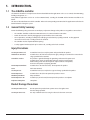
AcNet Pro
The AcNetPro Controller
OPERATION
AND INSTALLATION
MANUAL
On Line Access control
IMPORTANT NOTICE
All information and data contained in this document is proprietary and confidential. CROW Electronic Engineering Ltd. shall not be liable, in any event, for any claims for damages or any other remedy in any
jurisdiction whatsoever, whether in an action in contract, tort (including negligence and strict liability) or any other theory of
liability, whether in law or equity including, without limitation, claims for damages or any other remedy in whatever jurisdiction,
and shall not assume responsibility for patent infringements or other rights to third parties, arising out of or in connection with
this document. Further, CROW Electronic Engineering Ltd. reserves the right to revise this publication and to make changes
to its content, at any time, without obligation to notify any person or entity of such revision changes. These materials are
copyrighted and any unauthorized use of these materials may violate copyright, trademark, and other laws. Therefore, no part
of this publication may be reproduced, photocopied, stored on a retrieval system, or transmitted without the express written
consent of CROW Electronic Engineering Ltd. Any new issue of this document invalidates previous issues.
©CROW Electronic Engineering Ltd. 2005, 2006. All rights reserved.
Information in this document is subject to change without notice. No part of this document may be reproduced or transmitted
in any form or by any means, electronic or mechanical, without express written permission of CROW Electronic Engineering
Ltd..
ACTEC Series
P/N 7102003 Rev.B.
The AcNetPro Installation Manual July 2008
2
TABLE OF CONTENTS
1. INTRODUCTION................................................................................................................................................. 4
1.1 The AcNetPro controller……………………………………………………………………................... 4
1.2 General Safety Summary......................................................................................................................... 4
1.3 EMI Protection......................................................................................................................................... 5
1.4 Step by step installation.......................................................................................................................... 6
2. THE ELECTRONIC BOARD AND THE PCB JUMPERS.......................................................................................... 7
3. POWER SOURCES AND BOARD CONSUMPTION.............................................................................................. 8
4. CARD READERS TYPES AND CONNECTION..................................................................................................... 9
4.1 Connecting the Proximity Reader Range………………………………………………………............ 9
5. DOOR CONTACTS AND INPUTS DEVICES....................................................................................................... 10
6. LOCK DEVICE - RELAY OUTPUTS CONNECTION............................................................................................. 10
7. RS232 / RS485 SERIAL PORT CONNECTION...................................................................................................11
7.1 RS232 port. Jumpers JP2........................................................................................................................11
7.2 RS485 port. Jumpers JP2........................................................................................................................11
7.3 Setting the controller address...............................................................................................................13
8. PC to ACNETPRO CONTROLLER COMMUNICATION ACCESSORIES (optional)……......................................14
8.1 The CR40485 USB / RS-485/422 converter Installation instructions…. ……….…….……….……...14
1. Introduction.....................................................................................................................................15
2. Connecting the CR-40485 to RS-485 devices................................................................................ 16
3. Connecting the CR-40485 to RS-422 devices................................................................................ 16
4. Connections......................................................................................................................................17
5. Power and Earthing Considerations................................................................................................17
6. Installation of the driver for windows............................................................................................17
7. Dipswitch Setting............................................................................................................................ 18
8. General Specifications.................................................................................................................... 18
8.2 The DS100: TCP/IP - RS232 Device Server…………………...…………………………….................. 19
1. General Description........................................................................................................................ 19
2. How to configure the DS100 through the LAN.............................................................................. 19
8.3 The RS485 to RS232/TTL/TCP-IP……………………………...………………………………........... 20
APPENDIX A : THE 10 COMMANDMENTS OF THE INSTALLER.......................................................................... 21
HOW TO CON TACT US…………………………………………………………………………………............ 23
3
The AcNetPro Installation Manual
1. INTRODUCTION.
1.1 The AcNetPro controller
The AcNetPro controller is a microprocessor electronic board dedicated to applications such as access control, alarm monitoring,
building management, etc….
Many different applications can be run on the AcNetPro board, according the the ROM and the firmware installed on the
board.
This manual described how to install the controller. Refer to the corresponding User Manual of the application installed on the
board for details of using the system.
1.2 General Safety Summary.
Review the following safety precautions to avoid injury and prevent damage to this product or any products connectd to it.
−
The controller should be installed at maximum distance of 1,5 meters from the 230v outlet.
−
Power disconnection is done by unplugging the system from the mains 230v outlet.
−
Service procedures, including assembly of the 230v plug, must be done by a qualify personnel. A safety approval
connector has to be used, according to the local standards.
−
The controller must be unpowered before opening.
−
A safety approval 12V battery back-up has to be used, according to the local standards.
Injury Precautions
Use Proper Power Cord
To avoid fire hazard, use only the power cord specified for this product.
Avoid Electric Overload
To avoid electic shock or fire hazard, do not apply a voltage to a terminal that is outside the range specified for that terminal.
Ground the Product
This product is grounded through the grounding conductor of the power cord
To avoid electric shock, the grounding conductor must be to earth ground.
Before making connections to the input or output terminals of the product,
ensure that the product is properly grounded.
Do Not Operate Without
To avoid electic shock or fire hazard, do not operate this product
Cover
with cover removed.
Use Proper Fuse
To avoid fire hazard, use only the fuse type and rating specified for this product.
Do Not Operate In
To avoid electic shock, do not operate this product in wet or
Wet/damp Conditions
damp conditions.
Do Not Operate In An
To avoid injury or fire hazard, do not operate this product in an explosive
Explosive Atmosphere
atmosphere.
Product Damage Precautions
Use Proper Power Source
Do not operate this product from a power source that applies more
than the voltage specified.
Use Proper mains Fuse
Use only a 20x5mm 0.5A fast acting fuse located at the mains connector.
The AcNetPro Installation Manual
4
Saftey Terms and Symbols
Terms in This Manual
These terms may appear in this manual :
WARNING. Warning statements identify conditions or practices that could
result in injury or loss of life.
CAUTION. Caution statements identify conditions or practices that could
result in damage to this product or other property.
Symbols on the product
The following symbols may appear on the product :
1.3 EMI Protection.
DANGER
High Voltage
Protectice Ground
(Earth) Terminal
ACTEC LTD terminals, including AcNetPro or Minilock terminals, are all based on microprocessors. They are installed in order
to operate 24 hours a day. In addition, since they must often control a given environment, ACTEC terminals may be connected
to various types of exterior elements such as card readers, electrical door opener, alarm detection device, printer, mainframe
computer and so forth.
Under such circumstances, this kind of system is subjected to some extremely difficult constraints directly related to :
1- Electro Magnetic Interferences (EMI) along the lines connecting the terminal to any exterior elements. Undesired voltage may
reach thousands of volts in case of lightnings.
2- The exterior elements themselves. In most cases, they are not supplied by ACTEC LTD but are chosen in response to the
constraints of the particular installation site (local distributors, national operating standards, etc.).
All ACTEC LTD equipment is provided with internal protection devices against all such interference. (These devices include
varistances, protection diodes, etc.). However, since ACTEC LTD. Terminals may be installed in a variety of operating environments,
there are a certain number of basic rules of thumb that should be followed in order to provide extra protection.
It is absolutely imperative that, from the moment a ACTEC LTD terminal is installed, the individual responsible for the
installation rigorously adhere to all the directives listed below. Should any of these directives not be rigorously adhered
to, Crow Data Systems will not assume responsibility for any problems or malfunctions that might be encountered as a
result of such non-compliance.
1.
The control unit (housing the microprocessor) must never be installed inside a high voltage electrical power box and must
never be placed in close proximity to large transformers or high voltage/current source devices. Since the controller may
require maintenance, it is important to consider the accessibility of the unit.
2.
The AcNetPro board must be separately grounded. Therefore, one must verify in advance whether the installation site
provides adequate grounding facilities.
3.
The cover or case that contains the control unit housing the microprocessor must be tightly screwed down or locked in
place.
4.
It is essential to plug the ACTEC terminal’s 230 volt sector cable into a “clean” line (i.e., a line not being
used other
pieces of heavy equipment) or into an length line, which has been specifically allocated to the terminal, with a good
earth ground.
5.
Never use the system cables guide to pass wires from another system, like loud bells, electric door openers, etc ...
6.
Four categories of cable go to, or from, the terminal:
−
−
−
−
−
5
The 230 volt sector cable
The cables connecting badge-readers, alarm entries and push-buttons
The communication cable
The cable connecting the electrical door opener or an exterior release device
These categories must be installed as far as possible one from the other.
The AcNetPro Installation Manual
1.4 Step by step installation
Step 1:
Install the AcNetPro housing on the wall or the dedicated emplacement and pay attention to the following points:
A. Easy access to the unit
B. Effective Ventilation to the unit
C. Clear Electromagnetic Environment (see 1.3)
Step 2: Set the kind of communication used (see par. 7)
Step 3: Set the controller address through jumper DS1 (see par. 7.3). On installation where several AcNetPro boards
are used, avoid using the same address for different boards.
Step 4: Connect the card reader as explained on par. 4 and pay attention to the following points:
A. Select the technology used through jumper DS1
B. For Wiegand technology, install jumpers JP3 and JP4.
C. Power the card readers according to its consumption, see its technical manual.
Step 5: Connect the electric door opener using 20 AWG wires as explained on par. 6. Pay attention to the following points:
A. When using a DC voltage to an electric door opener, installed a diode ON THE LOCK ITSELF.
B. When a Fail safe opener is used:
C. Connect the opener between the CO and NC relays outputs.
Step 6:
Connect the different detectors between the corresponding inputs (I1 to I11) and the 0v, as explained in par. 5. The detector operating mode (NO or NC, time zones, etc..) is defined by software. (see User manual of the corresponding application).
Step 7:
Connect an effective ground to the dedicated lag located at the protective ground pin in the controller
housing. Use a proper tool to fix the ground wire into the lag or solder it.
Step 8: Connect the mains (230v). Use a 4mm wide strip to attach the mains cable to the proper fixation located on
the upper left corner, near the main grounding stud, inside the controller housing.
Step 9: Conect the battery pack (12V/7Ah max.) using 20 AWG wires as explained in par. 3
Step 10: Programme the system, if required, as described on the User Manual of the application used.
The AcNetPro Installation Manual
6
2. THE ELECTRONIC BOARD AND THE PCB JUMPERS.
R 4nc
R 3nc
R4c R4no R3c R3no
12Vdc
0v
R2nc
R1nc
Tx /H
R 2c R 2no R 1c R1no 0v Rx /L I11 I10 I9 0v I 8 I7
J5b
J5a
J4
J7
J 6b
RS 232
:::
JP2
I6 I5 0v I4 I3 I2 I
..
JP 4 . .
JP 3
0v
J 6a
0v
Vcc
Clk 1/I14
RS485
RS
Driver
RS 485
RL 4 RL 3 RL 2 RL 1
Led 11
Led1
Alarm Input indicators: Off if input closed
J1
Dat 1/I15
Led 1
Led 2
Lon1
Buz 1
0v
ROM
BC 4100
Rev . B
CPU
Vcc
Clk 2/I12
Dat2/I13
Lithium Cell
JP 1
Lithium
Cell
Reset
Eprom /
Flash
J2
DS1
Led 4
Led 5
Lon 2
Buz 2
Fig. 2: The AcNetPro Electronic board
DS1 : Board Address and Reader Technology:
J7 : Power
10Vdc to 13Vdc/0,5 A
AcNetPro:
DS1/1 to 5 : Board Address
J5: 4 relays
24v / 1A
AcNetPro2/3:
DS1/1 to 5 : Board Address
J1 : Reader 1
DS1/6,7,8 : Reader Technology:
6 on: Wiegand (Up to 50 bits) with parity check
7 on: Wiegand (Up to 50 bits) without parity check
8 on: Not in use.
J2 : Reader 2
JP1: Lithium Cell on/off
JP2: Selection
RS232/RS485:
J4 : serial Port
RS232 or RS485
to PC or printer
654
Note: For setting DS1 see page 10
The AcNetPro Installation Manual
654
:::
:::
RS232
RS485
12 3
JP3/4:
To be installed if reader 1/2 with
Wiegand interface.
7
J6 : 11 Alarm Inputs
123
3. POWER SOURCES AND BOARD CONSUMPTION
The board must be powered by 12Vdc. Nude, without any card reader, the board consumption is 100 mA max. The maximum
consumption authorised through the Vcc of the board is 300 mA.
Notes: Card readers consuming more than 250mA CANNOT be powered by the AcNetPro Vcc output.
- A safety approved 12V battery pack has to be used, according to the local standards.
R 4nc
R 3nc
R4c R4no R3c R3no
Power
Supply
12Vdc
0v
J5b
R2nc
R1nc
R 2c R 2no R 1c R1no 0v
J5a
J
J7
RS 23
:
JP2
R
RL 4 RL 3 RL 2 RL 1
BC 4
Rev
RemindeR!
Lithium Cell
DON’T CONNECT THE READER’S RED WIRE TO VCC OF THE PCB CONTROLLER.
JP 1
Lithium
The AcNetPro Installation Manual
Cell
Reset
DS1
8
4. CARD READERS TYPES AND CONNECTION
The AcNetPro controller may recognise many kind of reader technologies, selected by jumpers JP4/6,7,8. Hereunder the
connection for the most popular one (magnetic and proximity). For other technologies, refer to the relevant manual.
4.1 Connecting the Proximity Reader Range
It is adviced to use the ACTEC proximity reader range.
PR 103/104 – a 125 KHz models or smart reader – a 13,56 MHz model
Note 1: for the Wiegand interface only :
Install mini jumper on JP3 for reader No.1 and on JP4 for reader No.2
PR 104 Anti Vandal
PR 103 Prox
PR 106 Prox Pincode
Type of cable:
8 shielded wires, 22 AWG. Maximum length: 100m.
Interface:
ISO2 (clock/data) or Wiegand (data0/data1)
SW - 7 Fingerprint (refer to the
relevant Manual)
PR TYPE READERS - CABLE CONNECTION
Reader / ISO2 Interface
(Proxpoint, etc…)
Reader / Wiegand Interface
(PR 03/04/06, etc..)
ACNET 200 PCB
Reader 1/2
+DC
+DC
Red
12Vdc
GROUND
GROUND
Black
0v
CLOCK
DATA 0
Green
CLK1/CLK2
DATA
DATA 1
White
DAT1/DAT2
DATA RTN (If exists)
DATA RTN
GREEN LED (If exists)
BLUE LED
RED LED (If exists)
GREEN LED Orange
LED1/LED4
BEEPER (If exists)
BEEPER
BUZ1/BUZ2
9
Brown
Yellow
The AcNetPro Installation Manual
0v
Note 2: Refer to the reader manufacturer instruction manual for reader operation details.
AcNetPro Dip switches DS1
ISO 2 INTERFACE (Clock/Data) :
Any Wiegand card
6 bits with parity
6
6
up to 50
7
7
7
checking
based on ISO2
format.
8
8
8
6
7
8
off
WIEGAND INTERFACE (See also note 1 below) :
on
DS1
off
on
DS1
off
off
on
on
DS1DS1
6
7
8
6
7
8
off
off
on
Any Wiegand card
up to 506 bits6with parity
7
7
checking8 based
on format:
8
PE …. Data
off bits
off
on
on ….PO
on
DS1DS1
6
7
8
off
DS1DS1
on
Any Wiegand card
up to 50 bits without
parity checking
DS1
NOTE! Bfore connecting the PR 106 – make sure to reprogram it to Motorola output signal.
Read PR 106 instruction for details.
5. DOOR CONTACTS AND INPUTS DEVICES
A magnetic contact, passive infra-red unit, request to exit switch or any other form of dry contact can be monitored via the
Toplock system.
All the eight standard inputs can be set up, via software, so as to open doors when activated, activate sirens/bells or just inform
security of a change of state of a monitored device.
Protection against RFI interferences:
The following must be rigidly adhered to, in order to prevent malfunctions or interruptions :
−
If the distance between the alarm detector, push-button, etc., and the electronic board is greater than 10 meters, use a
shielded cable and connect the shields to the ground point of the control unit.
−
Always ensure that a distance of at least 50 cm, separates the connecting cables from both high-tension cables and
electrical door opener cable.
Example of a Normally Open or Normally Closed switch
connected to input I1.
I6 I5 0v I4 I3 I2 I1 0v
controller
ACNET
J 6a
6. LOCK DEVICE – RELAY OUTPUTS CONNECTION
The Four relays on the controller can support a maximum of 24V @ 1 Amp. Do not try to switch higher voltage than this as
it may damage the controller. See figure below, for details of wiring an electronic release. The function of each relay is user
definable in the software.
+12v
0v
R 1c R 1no
+•
J 5a
Relay 4 Relay 3 Relay 2 Relay 1
Controller
ACNET
R#no : Normally Open contact
R#nc : Normally Closed contact
R#c : Common contact of the relay
The AcNetPro Installation Manual
Always fit a
•- Diode across a DC
electronic lock,
to be fitted at the
lock end.
10
Important notes:
1.
If the release mechanism has a charge that exceeds the authorised limit or has a strong inductive charge (as in the case,
for example, of revolving doors or turnstiles), it will be necessary to use an intermediate relay between the system
and the charge. THE CHARGE MUST BE POWERED WITH A SEPARATE POWER SUPPLY. The intermediate relay and the
electronic board may be powered with the same power supply, the one of the board for example.
2.
The cable connecting the release mechanism to the control unit (or to the intermediate relay) must be isolated, and
there must therefore be a distance of at least 50 cm, between this cable and all the other cables.
7. RS232 / RS485 SERIAL PORT CONNECTION.
If the controller has to be connected to a PC or a printer at less than 30 meters, its RS232 port may be used.
If the distance is bigger than 30 meters or if several controllers must be connected together to a PC or a printer, the RS485 port
must be used as follows.
The characteristics of the serial transmission is : asynchronous serial transmission, 9600 bauds, 8 data bits, no parity, 2 stop
bits.
7.1 RS232 port. Jumpers JP2: The three signals 0v, Rx and Tx (3 shielded wire 22 or 24 AWG. Maximum distance: 30m) are connected to the PC
(or the printer) as follows:
D25 plug- computer end
D9plug- computer end
ACNET J4 board pins:
Pin 7 (Ov.)
Pin 5 (0v)
0v.
Pin 2 (Transmit)
Pin 3 (Transmit)
Rx
Pin 3 (Receive)
Pin 2 (Receive)
Tx
7.2 RS485 port. Jumpers JP2:
Connect the controllers as follows:
Port COM on PC :
D9
Connect the cable shield only at the
RS 232/RS 485 interface.
3
2
5
Rx
Tx
0v
RS232
RS485
RS 232/RS 485
Interface
Connect the interface to a good earth
RS485 bus: 1,2 Km. Shielded twisted pair cable 22/24 AWG
1 on
Tx/H 2 off
3 off
4 off
DS1 5 off
JP2
6
7
ACNETPRO
8
:::
11
1 on
Tx/H Rx/L
2 off
3 off
4 off
DS1 5 off
JP2
6
7
ACNETPRO
8
:: :
1 on
Tx/H Rx/L
2 off
3 off
4 off
DS1 5 off
JP2
6
7
ACNETPRO
8
:::
The AcNetPro Installation Manual
1 on
Tx/H Rx/L
2 off
3 off
4 off
DS1 5 off
JP2
6
7
ACNETPRO
8
:::
Notes:
1.
Do not connect the communication cable screen at any point other than at the RS232/RS485 interface end.
2.
It is imperative that the interface has a good earth ground through the mains. The importance of a good earth ground
cannot be overemphasized. Performance of the protection is directly related to the efficiency of the grounding system.
3.
Each ACNET board must have its own address selected by jumpers DS1/1-5, as shown on page 13.
Protection against RFI interferences:
Most of the interference will come by induction to the cable shield, on which high and very high voltage may appear because
of RFI interferences or lightning bolts.
To prevent perturbations, the following rules must then be respected:
1.
Use a shielded 22AWG triple-wire cable (“Receive”/”Transmit”/0v) for the RS232 connection and use a shielded 22 AWG
twisted pair cable for the RS485 connection.
2.
A good quality cable shield must be used and the shield must be connected to a strong earth. The shield should be from
copper rather than aluminium, since the latter provides only partial attenuation.
3.
All communication cable shieldings should be connected to only one extremity (and not both), in order to avoid the
problem of “ground loops”. Whereas the connection for the RS485 wire shield should be carried out at the level of the
concentrator and the connection for the RS232 wire shield should be carried out at the level of the terminal.
4.
A distance of at least 50 cm must separate all such connecting cables from high-tension cables, from cables connected
to an electrical power box controlled by the system, or from any cables capable of generating strong interference (such
as cables connected to high-power motors, generators, wireless telephone, etc.). Since it is often located besides a
variety of cables, the external telephone line can also be a source of strong interference.
5.
Extremely high tension produced by lightning bolts can enter the terminals through these above lines. Such tension can
reach the level of hundreds of thousands of volts. It is therefore advised to use the ACTEC SP200 protection unit at the
AcNetPro level. (This protection is included in the RS232/RS485 interface)
The AcNetPro Installation Manual
12
7.3 Setting the controller address.
In order to programme the system, each controller has to have a unique address which is defined with jumpers JP4 & JP3:
AcNetPro is addresses from 00 to 31 throug jumpers DS1/1 to DS1/5.
13
The AcNetPro Installation Manual
8. PC to ACNETPRO CONTROLLER COMMUNICATION
ACCESSORIES
8.1 CR40485 USB / RS-485/422 CONVERTER
1.Introduction....................................................................................................................15
2.Connecting the CR-40485 to RS-485 Devices.................................................................16
3.Connecting the CR-40485 to RS-422 Devices.................................................................16
4.Connections...................................................................................................................17
5.Power and Earthing Considerations...............................................................................17
6.Installation of the driver for WindowS...........................................................................17
7.Dipswitch Setting............................................................................................................18
8.General Specification.....................................................................................................18
CR40485
CR40485
USB to RS485
Converter
USB to RS422 / RS485 Converter
GND
RD RD +
TD -
A-
TD +
B+
GND
GND
AB+
GND
RS-485 - 2-Wires
AB+
GND
The AcNetPro Installation Manual
RS-485
Device 2
Up to
31
devices
INSTALLATION INSTRUCTIONS
RS-485
Device 1
RS-485
Device 31
14
1. Introduction
The CR40485 is a USB (Universal Serial Bus) port to 2 or 4 wire RS-485/422 converter. That can be set up for an RS-422 or RS485 network.
A pair of LEDs shows when RS-485/422 data is being received or transmitted. The USB side permits quick setup. Just plug in the
converter and Windows will install the drivers and set up the converter. The USB supplies power so no separate power supply
is needed.
The CR40485 is a cost-effective device for transfer serial data over USB USB/RS485 is designed to make serial port expansion
quick and simple. Connecting to a USB port on a computer or USB hub, this device instantly add serial communication ports
to your system.
By plugging the device into the USB port, it is automatically detected and installed. There are no IRQ & COM port conflicts, since
the port doesn’t require any additional IRQ, DMA or memory on the system.
This USB/RS485 provides instant connectivity to 485 communication devices for factory automation, multi-drop data collection
devices, barcode readers, time clocks, scales, data entry terminals, PC to PC long-distance communications.
The CR40485 is a cost-effective module for transfer serial data over USB. It allows you to connect your serial devices to systems
using a USB interface. Connecting the CR40485 to a PC, you get one RS-422/485 port. The “Self Tuner “chip auto-tunes the
baud rate and data format to the Rs-485 network. The CR40485 module derives the power from the USB port and doesn’t need
any power adapter. It also features a high-speed 115.2 Kb/s transmission rate, and supports various independent RS-422/485
Ports.
15
The AcNetPro Installation Manual
2. Connecting the CR-40485 to RS-485 Devices
Where 2-wire operation is required the Transmit and Receive signals should be connected together in pairs as below
(see Figure 2).
CR40485
USB to RS485
Converter
Make sure to set the DIP SW on PCB to “Half Duplex RS-485 2-Wires” mode.
GND
RD RD +
TD -
A-
TD +
B+
GND
GND
RS-485
Device 1
RS-485
Device 2
AB+
GND
Up to
31
devices
RS-485 - 2-Wires
RS-485
Device 31
AB+
GND
Figure 2
3. Connecting the CR-40485 to RS-422 Devices
Where 4-wire operation is required the Transmit signals should be connected to the corresponding Receive signals of the
devices (see Figure 3).
CR40485
USB to RS485
Converter
Set the DIP SW on PCB to the required mode of operation.
GND
RD -
TDA -
RD +
TDA +
TD -
RDA -
TD +
RDA +
GND
GND
TDA TDA +
RDA RDA +
RS-422
Device 1
RS-422
Device 2
GND
RS-422 - 4-Wires
Up to 31
devices
TDA TDA +
RDA RDA +
RS-422
Device 31
GND
Figure 3
The AcNetPro Installation Manual
16
4. Connections
The RS-422 specification recommends 24AWG twisted pair cable with a shunt capacitance of 16 pF per foot and 100 ohm
characteristic impedance. While the RS-485 specification does not specify cabling, these recommendations should be used for
RS-485 systems as well.
It can be difficult to quantify whether shielding is required in a particular system or not, until problems arise. We recommend
erring on the safe side and using shielded cable. Shielded cable is only slightly more expensive than unshielded.
There are many cables available meeting the recommendations of RS-422 and RS-485, made specifically for that application.
Another choice is the same cable commonly used in the twisted pair Ethernet cabling. This cable, commonly referred to as
Category 5 cable, is defined by the EIA/TIA/ANSI 568 specification. The extremely high volume of Category 5 cable used
makes it widely available and very inexpensive, often less than half the price of specialty RS422/485 cabling. The cable has a
maximum capacitance of 17 pF/ft (14.5 pF typical) and characteristic impedance of 100 ohms.
Category 5 cable is available as shielded twisted pair (STP) as well as unshielded twisted pair (UTP) and generally exceeds the
recommendations for RS-422 making it an excellent choice for RS-422 and RS-485 systems.
5. Power and Earthing Considerations
Unlike some RS232 to RS485 converters, the CR40485 will always be able to take the power it needs from the PC’s USB port.
It’s recommended to connect a solid earth/ground connection. It is also advisable to connect at least one of the ground pins
on the unit’s RS422/RS485 connector (via a 100R resistor) to the ground/earth conductor in the RS422/RS485 connecting cable.
The resistor will help to limit current if connected devices have different ground potentials.
6. Installation of the driver for Windows
17
−
Plug the converter into an available USB port on your computer.
−
A screen will appear, telling you that there is a new device plugged into the USB bus.
−
Click on the Next > button.
−
New screen will appear.
−
Make sure Search for the best driver for your device is selected,
−
Then select the Next > button.
−
New screen will appear.
−
Make sure CD drive is selected. Insert the attached CD into the CD Drive.
−
Then select the Next > button.
−
New screen will appear.
−
Make sure FTDI Converter is listed as the device.
−
Then select the Next > button.
−
The screen above will appear.
−
Click the Finish button to complete the installation.
The AcNetPro Installation Manual
7. Dipswitch Setting
The dip switches allow the module to be configured for two-wire or four-wire, RS-422 or RS-485 modes. In two-wire mode the
TD (-) and RD (-) are tied together and so are TD (+) and RD (+) .
SW1
SW2
SW3
MODE Description
ON
ON
OFF
Tx or Rx Half Duplex
RS-485 2-Wires
ON
OFF
ON
Tx always Enable ,Rx Enable only while transmission off
RS-422 , 4-Wires ,Echo off.
OFF
ON ON
OFF
Tx Enable only during transmission, Rx always Enable.
RS-422 4-Wires.
OFF
OFF
ON
Tx always Enable, Rx always Enable. RS-422, 4-Wires,
Echo on.
8. General Specification:
•
Standard:
EIA RS-485
•
Ports:
1 x RS485 1 x USB
•
Max Distance: 1200 m
•
Data Rates:
300 Baud up to 115k bps
•
Isolation:
None
•
LED's:
Red Led-Tx indicator, Green Led Rx Indicator.
•
Power:
from USB
•
Compatibility: USB 1.1 standard
•
Input: USB protocol
•
Output:
RS-422/485 protocol
•
Cable:
USB type A connector (Type A to Type B cable provided).
•
RS-422 Signal:
RX+, RX-, TX+, TX-
•
RS-485 Signals:
DATA+, DATA-
•
“Self Tuner” inside, support multiple Baud Rate and multiple Data Format
•
Mounting: wall mounting.
•
Temperature:
Operating: 0°C to 50°C
Storage: -20°C to 60°C
•
Humidity:
Operating: 10% to 80%, non-condensing
Storage: 5% to 90%, non-condensing
•
Dimensions: 95 mm x 65 mm x 37 mm
•
Driver supported: Windows 98 / ME / 2000 / XP
The AcNetPro Installation Manual
18
8.2 The DS100: TCP/IP - RS232 Device Server
1.
General Description
The DS100 is a TCP/IP to RS232 Device Server. It allows to connect ACTEC controllers to an Ethernet 10-BaseT
TCP/IP network.
2. How to configure the DS100 through the LAN
−
Connect the DS100 to Power with a 9VDC power jack. (The (+) inside).
−
Connect the DS100 to the LAN via RJ-45 cable.
−
Install, from the delivered CD, the Tibbo Device Server Toolkit on your PC.
−
Go to Start-Programs-Tibbo-Tibbo Device Server Manager
−
The program should auto detect the DS100. Its initial IP address is 127.0.0.1
−
Click on the IP address and then on <Change IP> and set the IP according to your LAN settings.
−
Consult your network administrator before setting the IP address.
−
Click on <DS Settings>.
In “Network settings” tab set:
−
Routing Mode = Slave
−
Device server IP = xxx.xxx.xxx.xxx : <Port Number>.
−
By default, the port number is 1001. It can be changed to another number, e.g., 10001
−
Transport protocol = TCP
In “Serial Properties” tab set
19
−
Serial interface = RS232
−
Baud rate = 4800 bps (or other according to the specific controller)
−
Parity = None
−
Flow control = None
−
Click OK to exit the Properties screen.
−
Click OK to exit the Device Server Manager.
The AcNetPro Installation Manual
8.3 RS485 to RS232/TTL/TCP-IP MINI Interface
The RS232/RS485 Mini interface is adapted for the Crow AcNetPro-DBL which includes two controllers : it allows to connect
together these two controllers, via their RS485 port to either a RS232 or a TTL or a TCP/IP network.
Warning ! : The RS485 side of this Mini interface does not include lightning protections !
77
RS 232
Port /TTL
Tx
Rx
0v
L
H
VCC
0v
12V
LD 2
(Rx /Tx )
RX /L TX /H
RS 485 Port
J2
J1
SW 1
RJ 45
RS 232
:::::
44 mm
TCP /IP bridge
TTL
LD 1
(on)
RX /L TX
RS 485
/H
Port
AcNetPro Board 2
AcNetPro Board 1
BI 1200- A
AcNetPro -DBL housing
−
LD1 is a green led lit when power is on.
−
LD2 is a bicolor led which shows the communication status of the RS232 line :
Green flashes when reception on Rx line
−
Red flashes when transmission on Tx line.
−
SW1 selected the electric levels at the RS232/TTL port:
−
−
SW1= RS232 : Rx/Tx : +/-12Vdc
−
SW1= TTL : Rx/Tx : +5v/0v.
The board needs a 8-12Vdc power and its consumption is 40mA max. (or 250mA when using the TCP/IP bridge).
The Mini interface may be used in three different configurations:
Connector
J1
AcNetPro-DBL to RS232 port SW1
on RS232
AcNetPro -DBL to TTL port
SW1 = TTL
AcNetPro -DBL to TCP/IP
SW1=TTL
To a PC
(RS232 levels)
(To other devices)
TTL Levels
Not used (see note 1)
L
To Rx/L input of AcN. boards
To Rx/L input of AcN. boards
To Rx/L input of AcN. boards
H
To Tx/H input of AcN. boards
To Tx/H input of AcN. boards
To Tx/H input of AcN. boards
Vcc
5 Volts OUTPUT / 200mA.
5 Volts OUTPUT / 200mA.
5 Volts OUTPUT / 200mA.
0v
0v Power
0v Power
0v Power
12V
8-12Vdc power
8-12Vdc power
8-12Vdc power
Tx
Rx
0v
Note 1:To connect the mini interface to a TCP/IP network, insert a 10-Base-T TCP/IP bridge on the J2 connector.
The network has to be connected to the RJ45 of the TCP/IP interface
Note 2:Any controller can be use insted of the AcNetPro controllers.
The AcNetPro Installation Manual
20
APPENDIX A : THE 10 COMMANDMENTS OF THE INSTALLER.
1. Never pass the door opener cable near the other cables:
it must be at least 10cm from all other cables.
10 cm .
DC+ -
2. Use always a diode if the door opener is DC powered
Separate
Power Supply
12Vdc
No Relay
Common
+
Co
No
0V.
Controller
-
RS 232/RS 485
RS 485
Lo
Interface
3. If the door opener consumption is more than 24V/1A, use an
intermediate relay.
4. Always install a 120 ohms terminator resistor at both ends of the
RS485 line.
Hi
Last
Controller
5. Never connect a controller to the RS485 bus farther than 3 meters.
RS 485
Lo
Max . 3
Hi
Controller
6. Link all the RS485 wire shields together and connect it at the
RS232/RS485 interface end and NOT at the controllers end.
RS 232/RS 485
Interface
Gnd
RS485 Bus
Lo
Hi
Controller
Lo
Controller
Hi
7. Use a very good earth at the interface.
8. Use a surge protection if the region is inclined to lightning.
(like the SP200 unit)
Controller
9. Never install a controller or its cables near a high voltage line or a
heavy duty electric devices (Motors, transformers, high voltage
sources, etc…)
Power
Supply
12 Vdc
21
Controller
10. Never use the same power supply for the controller AND the
door opener
The AcNetPro Installation Manual
CROW ELECTRONIC ENGINEERING LTD. (Crow) WARRANTY POLICY CERTIFICATE
This Warranty Certificate is given in favor of the purchaser (hereunder the “Purchaser”) purchasing the products directly from
Crow or from its authorized distributor.
Crow warrants these products to be free from defects in materials and workmanship under normal use and service for a period
of 24 months from the last day of the week and year whose numbers are printed on the printed circuit board inside these
products (hereunder the “Warranty Period”).
Subject to the provisions of this Warranty Certificate, during the Warranty Period, Crow undertakes, at its sole discretion and
subject to Crow’s procedures, as such procedures are form time to time, to repair or replace, free of charge for materials and/or
labor, products proved to be defective in materials or workmanship under normal use and service. Repaired products shall be
warranted for the remainder of the original Warranty Period.
All transportation costs and in-transit risk of loss or damage related, directly or indirectly, to products returned to Crow for
repair or replacement shall be borne solely by the Purchaser.
Crow’s warranty under this Warranty Certificate does not cover products that is defective (or shall become defective) due to:
(a) alteration of the products (or any part thereof) by anyone other than Crow; (b) accident, abuse, negligence, or improper
maintenance; (c) failure caused by a product which Crow did not provide; (d) failure caused by software or hardware which
Crow did not provide; (e) use or storage other than in accordance with Crow’s specified operating and storage instructions.
There are no warranties, expressed or implied, of merchantability or fitness of the products for a particular purpose or otherwise,
which extend beyond the description on the face hereof.
This limited Warranty Certificate is the Purchaser’s sole and exclusive remedy against Crow and Crow’s sole and exclusive
liability toward the Purchaser in connection with the products, including without limitation - for defects or malfunctions of
the products. This Warranty Certificate replaces all other warranties and liabilities, whether oral, written, (non-mandatory)
statutory, contractual, in tort or otherwise.
In no case shall Crow be liable to anyone for any consequential or incidental damages (inclusive of loss of profit, and whether
occasioned by negligence of the Crow or any third party on its behalf) for breach of this or any other warranty, expressed or
implied, or upon any other basis of liability whatsoever. Crow does not represent that these products can not be compromised
or circumvented; that these products will prevent any person injury or property loss or damage by burglary, robbery, fire or
otherwise; or that these products will in all cases provide adequate warning or protection.
Purchaser understands that a properly installed and maintained product may in some cases reduce the risk of burglary, fire,
robbery or other events occurring without providing an alarm, but it is not insurance or a guarantee that such will not occur or
that there will be no personal injury or property loss or damage as a result.
Consequently, Crow shall have no liability for any personal injury; property damage or any other loss based on claim that these
products failed to give any warning.
If Crow is held liable, whether directly or indirectly, for any loss or damage with regards to these products, regardless of
cause or origin, Crow’s maximum liability shall not in any case exceed the purchase price of these products, which shall be the
complete and exclusive remedy against Crow.
The AcNetPro Installation Manual
22
CROW ELECTRONIC ENGINEERING LTD.
ISRAEL
12 Kineret St.
Airport City, 70100 Israel.
Tel. +972-3-9726000
Fax. +972-3-9726001
E-Mail. [email protected]
www.thecrowgroup.com
LATIN AMERICA
5753 N.W 151st Street,
Miami Lakes, FL33014, USA
Tel. +1-305-823-8700
Fax. +1-305-823-8711
E-Mail. [email protected]
www.crowlatinamerica.com
USA
2160 North Central Road,
Fort Lee, NJ 07024, USA
Tel. +12019440005
Fax. +12019441199
E-Mail. [email protected]
www.crowelec.com
ITALY
VIA Giulianello 4/14
00178 ROMA, ITALY
Tel. +39-0676-12912
Fax. +39-0676-12601
E-Mail. [email protected]
AUSTRALIA
142 Keys Road Cheltenham
VIC 3192 Australia
Tel. +61-3-9553-2488
Fax. +61-3-9553-2688
E-Mail. [email protected]
www.crowaust.com.au
POLAND
Powazkowaka
01-797 Warszawa POLAND
Tel. +48-22-562-3000
Fax. +48-22-562-3030
E-Mail. [email protected]
These instructions supersede all previous issues in
circulation prior to June 2008.