1
CROW ELECTRONIC ENGINEERING LTD.
("Crow") - WARRANTY POLICY CERTIFICATE
This Warranty Certificate is given in favor of the purchaser (hereunder
the "Purchaser") purchasing the products directly from Crow or from
its authorized distributor.
Crow warrants these products to be free from defects in materials
and workmanship under normal use and service for a period of 24
months from the last day of the week and year whose numbers are
printed on the printed circuit board inside these products (hereunder
the "Warranty Period").
Subject to the provisions of this Warranty Certificate, during the
Warranty Period, Crow undertakes, at its sole discretion and subject
to Crow's procedures, as such procedures are form time to time, to
repair or replace, free of charge for materials and/or labor, products
proved to be defective in materials or workmanship under normal use
and service. Repaired products shall be warranted for the remainder
of the original Warranty Period.
All transportation costs and in-transit risk of loss or damage related,
directly or indirectly, to products returned to Crow for repair or
r ep l a ce m e n t sh a ll b e b o rn e s o le ly b y t h e Pu rc h a se r.
Crow's warranty under this Warranty Certificate does not cover
products that is defective (or shall become defective) due to: (a)
alteration of the products (or any part thereof) by anyone other than
Crow; (b) accident, abuse, negligence, or improper maintenance; (c)
failure caused by a product which Crow did not provide; (d) failure
caused by software or hardware which Crow did not provide; (e) use
or storage other than in accordance with Crowí s specified operating
and storage instructions.
There are no warranties, expressed or implied, of merchantability or
fitness of the products for a particular purpose or otherwise, which
extend beyond the description on the face hereof.
This limited Warranty Certificate is the Purchaser's sole and exclusive
remedy against Crow and Crow's sole and exclusive liability toward
the Purchaser in connection with the products, including without
limitation - for defects or malfunctions of the products. This Warranty
Certificate replaces all other warranties and liabilities, whether oral,
written, (non-mandatory) statutory, contractual, in tort or otherwise.
In no case shall Crow be liable to anyone for any consequential or
incidental damages (inclusive of loss of profit, and whether occasioned
by negligence of the Crow or any third party on its behalf) for breach
of this or any other warranty, expressed or implied, or upon any other
basis of liability whatsoever. Crow does not represent that these
products can not be compromised or circumvented; that these products
will prevent any person injury or property loss or damage by burglary,
robbery, fire or otherwise; or that these products will in all cases
provide adequate warning or protection.
Purchaser understands that a properly installed and maintained
product may in some cases reduce the risk of burglary, fire, robbery
or other events occurring without providing an alarm, but it is not
insurance or a guarantee that such will not occur or that there will be
no personal injury or property loss or damage as a result.
Consequently, Crow shall have no liability for any personal injury;
property damage or any other loss based on claim that these products
failed to give any warning.
If Crow is held liable, whether directly or indirectly, for any loss or
damage with regards to these products, regardless of cause or origin,
Crowí s maximum liability shall not in any case exceed the purchase
price of these products, which shall be the complete and exclusive
remedy against Crow.
-4-
ELECTRONIC ENGINEERING LTD.
ELECTRONIC ENGINEERING LTD.
P/N 7101439 Rev.D Y.A/YS/A.Y
ISRAEL
57 Hamelacha St.
Holon 58855 Israel.
Tel. +972-3-5569937
Fax. +972-3-5592981
e. [email protected]
w. www.thecrowgroup.com
BS-1 SIREN
High Power Siren With
Battery Back-up and Flashlight
USA
2160 North Central Road,
Fort Lee, NJ 07024, USA
Tel. +12019440005
Fax. +12019441199
e. [email protected]
w. www.crowelec.com
AUSTRALIA
429 Nepean Hwy. Brighton East
VIC 3187 Australia
Tel. +61-3-9596-7222
Fax. +61-3-9596-0888
e. [email protected]
w. www.crowaust.com.au
LATIN AMERICA
5753 N.W 151st Street,
Miami Lakes, FL33014, USA
Tel. +1-305-823-8700
Fax. +1-305-823-8711
e. [email protected]
w. www.crowlatinamerica.com
ITALY
VIA Giulianello 4/14
00178 ROMA, ITALY
Tel. +39-0676-12912
Fax. +39-0676-12601
e. [email protected]
POLAND
VIDICON SP.ZO.O.
15 Povazkowska St.
01-797 Warsaw Poland
Tel. +48-22-562-3000
Fax. +48-22-562-3030
e. [email protected]
INSTALLATION INSTRUCTIONS & USER MANUAL
Siren BS-1 Manual Installation
Flash Trigger:
The flashlight can be triggered by applying “low”
level to “FL-“ terminal. Flash duration is not limited
and the time of flashlight is set by control panel - as
long as trigger available the flashlight will be active
Tamper:
The tamper is normally closed while the housing is
closed with the screw, so in this state the tamper
terminals are shorted (0 Ohm) .The tamper will open
while opening the screw or by tearing the housing
from the wall.
Note: It’s essential to screw the tamper socket to
the wall properly.
Power Failure:
On Power Failure the siren and flashlight are
triggering, until power supply is restored or time out
period (5 minutes) expires.
Battery Protection
The Siren is supplied with protection against totally
battery discharge by cutting off the siren, when
voltage level falls down to less then 8Vdc.
BS-1 Features
The BS-1 siren is a new generation of professional
high power acoustic siren with battery back-up and
flashlight, which include all performance and reliability
for security alarm system.
Features:
Outdoor battery back-up siren with flashlight.
Double housing: External –3mm plastic
PC with UV, Internal – 0.8mm metal.
Continuous frequency modulated sound.
Tamper protection in 3 ways – Screw or
Cover opening or tearing housing from the wall.
Positive and negative alarm trigger inputs.
Trigger input to activate only the flashlight.
Siren period can set as follow trigger or 3 min
cutoff
Selector for lamp or xenon
Alarm by main power failure.
Protecting against totally battery discharge.
Plug Terminal for easy Installation.
Environmental immunity.
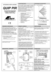
Installation Instructions
Functional Description Alarm Trigger:
1. Choose the mounting location for the siren –
the wall must be even and free of holes and
excessive protrusions.
2. Mark and drill 5 holes with the help of the attach
drill pattern plate (4holes for the housing base
and 1 for the tamper).
The alarm can be triggered by applying high or low
voltage to the “GO+” or “GO-“ inputs terminals
respectively. The sound and flashlight triggered
together.
Alarm siren duration depended on the Trigger selector
state:
F.T- Follow Trigger .
TMR- siren cutoff after 3 minutes,this state is
recommended in order to avoid violation of any
local regulations.
Note:Take a consideration about the wires
inputs in the housing base.
-1-
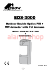
Terminal Block Connection
Terminal 1 - Marked “FL-” Trigger for the flashlight.
Connect it to an output in the Alarm System, Active
while the input is low.
Terminals 2 - Marked “GO+” Trigger for the siren
and the flashlight, Active while the input is high.
Terminals 3 - Marked “GO-” Trigger for the siren
and the flashlight, Active while the input is low.
Terminal 4 - Marked “GND” Connect to ground of
the control unit.
Terminal 5 - Marked “+12V” Connect to a positive
Voltage output of 13.6 – 14.2Vdc source (usually
from the alarm control unit).
Terminals 6 & 7 - Marked “ TAMPER ” If a Tamper
function is required connect these Terminals to a 24hour normally closed protective zone in the control
unit. If the front cover of the siren is opened or siren
box is tearing from the wall, an immediate alarm
signal will be sent to the control unit.
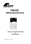
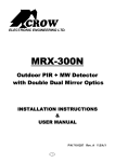
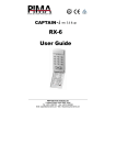
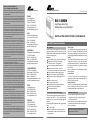
3. Open the siren housing (1 screw on the front),fig
1 and remove the metal cover (2 screws),fig2.
4. Unplug the terminal(5) on the siren driver
5. Mount the siren housing on the wall.
6. Connect the wires to the terminals(5).
Important: Cut off the power before you
make the connections.
7. Plug the terminal to the drive board.
8. Power on the system and check that it
function properly.
9. Connect the Back-up battery.
Important: Keep attention to the polarity of
the Battery, a reverse polarity can cause
damage to the driver circuit.
10 .M o un t the me ta l co v er b y 2 s cr ews .
11.Close the housing by 1 screw.
A
B
Fig 1
Siren BS-1 Specification
Sound Pressure Level
128dB
Fundamental Frequency
1850 Hz
Siren Tone
Yelp
Frequency Range
1300 ~ 2400 Hz
Flash Light
Power Supply Voltage
Lamp 12Vdc / 5W
13.8 ~ 14.2 Vdc
Charge Current Limit
250mA
Current consumption (Speaker and Strobe).
Standby: 8mA
Maximum Power
50W (Peak)
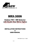
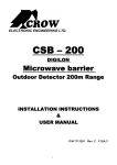
Fig 2
Siren Includes:
1-Horn
4-Tamper
2-Lamp
5-Terminal Block
3-Battery 6-Connector
1 Lamp selector
1
4
5
2 Trigger selector
SIREN BS-1
Alarm: 1600mA @ 13.8V DC
Trigger Level
Trigger Low = Max. 1Vdc
Trigger High = Min. 9Vdc
Siren Alarm Period
F.T- Follow trigger
6
TMR - 3min.
Input Impedance (Alarm / Flash / Trigger)
1K Ohm
Tamper Switch
N.C 28 Vdc Maximum current 0.1 A - open when
Backup Battery
Rechargeable Lead Acid Battery 12V up to 7.2Ah
Low Battery Level
Material
8 Vdc +/- 0.3Vdc
External Box: ABS (3mm thick).
Dimensions of unit
L=270mm X W=193mm X H=100mm
cover is removed
Internal Cover: Metal (0.8 mm thick).
Weight (Without Battery)
1.85 Kg
Operating temperature range
-30oC to +60oC
Case Protection Level
· Water splash resistant
3
2
· Plastic PC with UV protection
· Conformal coated circuit board
-2-
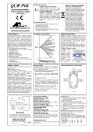
Fig 3
Fig 4
-3-