1
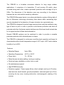
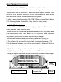
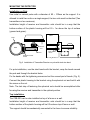
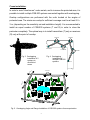
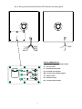
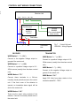
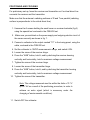
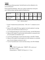
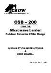
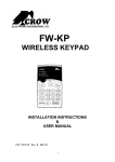
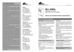
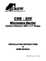
ELECTRONIC ENGINEERING INC.
CSB - 200
Microwave Barrier
Outdoor Detector 660’ x 17’ Range
INSTALLATION INSTRUCTIONS
&
USER MANUAL
P/N 7111267 Rev. 1.0 Y.S/A.Y
1
The CSB-200 is a bi-station microwave detector for long range outdoor
applications. It comprises of a transmitter (T) and receiver (R) which, when
mounted facing each other, create a perimeter protection with coverage of up to
200m. The dimensions of the detection area vary according to the distance
between the two units and the sensitivity calibration.
The CSB-200 Microwave barrier is an advanced detection system utilizing state of
the art Microwave technology eliminating false alarms while maintaining high
security standards for the detection of human intruders into a protected area.
The CSB-200 is designed to protect large areas and can easily be installed on any
type of fence or pole in order to provide a solid barrier protection and block all
perimeter activities; this barrier rejects interferences of birds and small animals due
to its original method of false alarm elimination.
Several CSB-200 systems can be combined in order to provide a complete
perimeter protection with unlimited space or shape.
The CSB-200 is designed for continuous round-the-clock operation and keeps its
characteristics within a wide temperature range of -40°C up to +60°C and a relative
humidity of up to 98%.
Features:
• Detection Range:
Up to 200m
• Operating Temperature:
-40°F to +140°F
• Power Input:
12 ~ 30 Vdc
• Detect human intruders walking, running or crawling.
• Quick and easy installation on pole, fence or wall.
• No maintenance required.
• High RFI/EMI Immunity.
• Protection against: Power supply failure, direct sunlight, wind up to 30 m/sec,
snow and rain, small animals, ground precipitation, snow and grass up to 0.5m,
removing the top cover, housing destruction, electromagnetic masking of the
receiver.
2
SELECTING MOUNTING LOCATION
The installation of the CSB-200 requires that the transmitter and the receiver face
each other, so that the two antennas may be correctly aligned.
The two units must be positioned in direct line at the edge of the area. Local
conditions of the protected zone must be free from obstacles like walls, fences,
trees and ditches or other microwave detectors and systems.
In order to ensure suitable operation of the CSB-200, type of ground should be one
of the following: Asphalt, Cement, Soil, Clay, Gravel or Grass (mown).
Avoid the following locations.
Avoid installation of CSB-200 on the following type of ground: Thick vegetation,
Grass (unmown), Water, Sand and Metal.
The ground must not have movable parts near the sensitive zone, any grassy areas
must be frequently mown, there should not be any flowing water, especially
longitudinally, ground where structural features may be changed.
The installation site should satisfy the following requirements (see fig. 1):
• The surface of the site should be leveled with a maximum slope angle of 15°.
• No obstacles as bushes or group of trees or walls, within a distance of 2.5m from
the centerline between two units.
• Depth of snow on the ground should not be more than 0.5m.
• Height of a grass on the ground should not exceed 0.3m. It is important to mow
the grass regularly to avoid its movement interfering with the microwave signal.
Maximum length of protection zone = 200 m
Maximum width of protection zone = 5 m
Maximum height of protection zone = 1.8 m
Maximum height of grass on
the ground = 0.3m
Maximum depth of snow on
the ground = 0.5m
Fig.1. Installation and Protection zone
3
Installation
Height
1 ~ 1.5 m
Dead Zone
2.5~3 m
MOUNTING THE DETECTOR
Installation on Pole
Use metal or cement poles with a diameter of 90 ~ 100mm as the support. It is
allowed to install two units on a single support; the two units must be identical (Two
transmitters or two receivers).
Installation height of receiver and transmitter units should be in a way that the
bottom surface of the plastic housing will be 0.9 ~ 1m above the top of surface
(ground and grass).
POLE
BAND
SPHERICAL
NUT
POLE
BRACKET
BAND INSERT
HOLES
BAND TIGHTENING
SCREW
Fig.2. Installation of Transmitter/Receiver on pole with steel wire band
For pole installation, use the steel bands with the bracket; wrap the bands around
the pole and through the bracket holes.
Fix the bands with the tightening screws and cut the unused part of bands. (Fig. 2).
Connect the plastic housing to the bracket using the spherical nut and hold it with
the screw on the nut.
Note: The last step of fastening the spherical nuts should be accomplished after
focusing the receiver and transmitter in the optimal position.
Top installation.
The CSB-200 can be also installed on top of a fence or a wall.
Installation height of receiver and transmitter units should be in a way that the
bottom surface of the plastic housing will be 0.3m above top of fence or wall.
The support should be mechanically connected to the fence to ensure reliability.
4
Cross installation.
In order to avoid “dead zones” under aerials, and to increase the protected area, it is
possible to install multiple CSB-200 systems connected together with overlapping.
Overlap configurations are performed with the units located at the angles of
protected area. The minimum overlap for sufficient coverage must be at least 2.5 ~
3 m, (depending on the sensitivity set and installation height). It is recommended to
install an equal number of CSB-200 systems (T and R) in order to close the
perimeter completely. The optimal way is to install transmitters (T) only or receivers
(R) only at the point of overlap.
Receiver
Receiver
Transmitter
Transmitter
Fig. 4. Overlapping
Installation of
multiple CSB-200
systems.
Fig. 3. Overlapping
installation of 2
systems to
avoid blind
zones.
r
ive
ce
Re
Transmitter
Receiver
Transmitter
Tra
nsm
itter
Tra
nsm
itter
r
ve
ei
ec
R
r
ve
ei
ec
R
Transm
itter
r
eive
Rec
Fig. 5. Overlapping Angle and Range Installation of CSB-200 systems for area protection.
5
Fig. 6. Wiring connections and Receiver LED indicators and tuning panel.
“TS”
“TS”
“NC”
“-“
“+”
“NC”
“DC”
“-“
“+”
SPECIAL ABBREVIATION:
AGB – automatic gain stabilization button
TC – test connector
LP – threshold level positive
TS
WN GUARD
LN
LP
LN - threshold level negative
WN - threshold level double negative
TS – tamper switch
TC
AGB
DC – distance control
NC – normal closed contacts
6
CONTROL UNIT WIRING CONNECTIONS
d
d
Receiver Unit
-12V+
TS TS
NC
NC
Control panel
ALARM
BOARD
(For normal closed
alarm circuit)
POWER
SUPPLY
12-30 V
+
-
Test button
+
-
DC
Transmitter
Unit
RECEIVER
Fig. 7. Control Unit and
CSB-200 – Wiring Diagram
TRANSMITTER
WIRE Marked “ - ” ( - 12V )
WIRE Marked “ + ” ( + 12V )
Connect to the negative Voltage output or
ground of the control unit.
Connect to a positive Voltage output of 12 30Vdc source (usually from the alarm control
WIRE Marked “ + ” ( + 12V )
unit).
Connect to a positive Voltage output of 12 30Vdc source (usually from the alarm control
unit).
WIRE Marked “ - ” ( - 12V )
Connect to the negative Voltage output or
ground of the control unit.
WIRES Marked “ TS ”
WIRE Marked “ DC ”
Connect these terminals to a 24-hour
normally closed protective zone in the control
unit. If the front cover of the detector is
opened, an immediate alarm signal will be
sent to the control unit.
WIRES Marked “NC”
These are the output relay contacts of the
detector. Connect to normally closed zone in
the control unit.
7
Apply 5-30 Volts from alarm station to the
terminal marked DC - TEST.
POSITIONING AND FOCUSING
For preliminary set-up, focus the receiver and transmitter as if a virtual direct line
connects the receiver and the transmitter.
Make sure that the antenna’s radiating surfaces of R and T are parallel (radiating
surface is perpendicular to the virtual direct line).
1. Unscrew the 6 screws holding the small cover on receiver backside (fig.6)
using the special tool enclosed in the CSB-200 set.
2. Make sure you switched on the power supply and outgoing electric circuit of
the sensor correctly as shown in fig. 7.
3. Connect a voltmeter to the output marked “TC” in the tuning panel, using the
cable, enclosed in the CSB-200 set.
4. Set the voltmeter to 10VDC measurements range, and switch it ON.
5. Loosen the screw of the receiver hinge.
6. Press the “AGB” button, hold it, and by declining the receiver housing
vertically and horizontally, look for maximum voltage measurement.
7. Tighten the screw of the receiver hinge.
8. Loosen the screw of the transmitter hinge.
9. Press the “AGB” button, hold it, and by declining the transmitter housing
vertically and horizontally, look for maximum voltage measurement.
10. Tighten the screw of the transmitter.
Note: The voltage measured must be within the limits of 2.7 V
up to 7.5V as a result of the positioning procedure, in order to
achieve an extra signal (which is necessary under the
changing of environmental conditions).
11. Switch OFF the voltmeter.
8
TUNING
Following the positioning process, threshold levels must be calibrated on the
receiver back panel.
During threshold calibrations, make sure to perform walk test by crossing the
area in different places walking upright and bending down.
Length of site
Walk test distance from
TR, RE in meters,
no less, than…
150 ~
200m
100m
75m
50m
40m
Less
then 30m
9.5 ~
10.5m
10 ~ 11m
11~
11,5m
13 ~
13,5m
16 ~ 17m
In all site
Fig. 8
Walk test distance
1. Set the 3 threshold level potentiometers – WN, LN, LP - clockwise to end of
route.
2. Observe LED marked WN (large negative level) while assistant is crossing
the area in the test distance as descried in fig. 8.
3. Turn the WN potentiometer counter-clock-wise slowly, until LED WN flashes.
4. Observe LED marked LP (positive level) while assistant is crossing the area
in the test distance as descried in fig. 8.
5. Turn the LP potentiometer counter-clock-wise slowly, until LED LP flashes.
6. Observe LED marked LN (small negative level) while assistant is crossing the
area in the test distance as descried in fig. 8.
7. Turn the LN potentiometer counter-clock-wise slowly, until LED LN flashes.
Note:
During CSB-200 standby state, “GUARD” LED is active and
the detector is ready.
During detection, “GUARD” LED fades for 5 ~ 10 sec.
9
WALK TEST
Following the tuning process, walk test should be performed.
1. Cross the area in different locations, choosing depressions and elevations.
2. Verify detection by observing the “GUARD” LED fade.
3. If necessary, make fine-tuning of the threshold levels LP and LN.
4. Replace the small cover on receiver backside (fig.6).
5. Screw the 6 holding screws using the special tool enclosed in the CSB-200
set.
Note:
After tuning the system it is recommended to check
functionality for 2-3 days, to verify the installation and
tuning.
10
ROUTINE TEST PROCEDURES
It is recommended to perform routine inspection of the system with the following
tests:
Walk Test
1. After tuning the sensitivity, connect 12Vdc power to the system.
2. Allow 2 minutes warm-up time.
3. Make sure that the protected area is cleared of all people.
4. Cross the middle part of the protected area.
5. An alarm signal should be received in the control unit for 3 Sec.
NOTE: Walk Test procedure should be conducted, at least once
a year, to confirm proper operation and coverage of the
detector.
Remote Test
1. Apply 5-30 Volts from control unit to the wire marked DC (Transmit remote
control), on the transmitter unit.
2. An alarm signal should be received in the control unit for 3 Sec.
NOTE: During regular operation it is recommended to conduct
remote test every day to confirm proper operation of all
system.
11
SPECIFICATIONS
Microwave Frequency
9.9 GHz
Modulation Frequency
2.5 KHz
Maximum Transmitting Power
10mW (Continues) 25mW (Peak)
Scope (Length of protection zone)
Max. 200 m
Lobe Width
Approx. 5 m
Lobe Height
Approx. 2m
Power Supply Voltage
12...30 V
Current consumption
Transmitter - 20 mA at 12Vdc
Receiver - 20 mA at 12Vdc
Relay contacts values
N.C 28 Vdc, Maximum current 0.1 A
Alarm Period
Tamper Switch
3 Sec (Max.)
N.C 28 Vdc Maximum current 0.1 A - open when
cover is removed
Detection Speed (Target velocity)
Remote testing
0.3 ... 10 m/sec
Built-in self-test generator simulates actual intrusion
signals
Flatness of ground
Approx. 0.3 m
Maximum height of grass on the
ground
Maximum height of snow on the
ground
Alarm output - switching over of relay
contacts for the time
Dimensions of unit (T / R)
w/o bracket
0.3 m
0.5 m
Minimum 3 Sec
260 x 210 x 85mm
Weight (T, R and accessories)
2 Kg
Operating temperature range
Weatherproofing
-40°C ~ +60°C
•
•
* Specifications are subject to change without prior notice.
12
All openings with gasket and sealed
Conformal coated circuit board
CROW LIMITED WARRANTY
(CROW) warrants this product to be free from defects in materials and
workmanship under normal use and service for a period of one year from
the last day of the week and year whose numbers are printed on the printed
circuit board inside this product.
CROW’s obligation is limited to repairing or replacing this product, at its
option, free of charge for materials or labor, if it is proved to be defective in
materials or workmanship under normal use and service. CROW shall have
no obligation under this Limited Warranty or otherwise if the product is
altered or improperly repaired or serviced by anyone other then CROW.
There are no warranties, expressed or implied, of merchantability or fitness
for a particular purpose or otherwise, which extend beyond the description
on the face hereof. In no case shall CROW be liable to anyone for any
consequential or incidental damages for breach of this or any other
warranty, expressed or implied, or upon any other basis of liability
whatsoever, even if the loss or damage is caused by CROW’s own
negligence or fault.
CROW does not represent that this product can not be compromised or
circumvented; that this product will prevent any person injury or property
loss or damage by burglary, robbery, fire or otherwise; or that this product
will in all cases provide adequate warning or protection. Purchaser
understands that a properly installed and maintained product can only
reduce the risk of burglary, robbery or other events occurring without
providing an alarm, but it is not insurance or a guarantee that such will not
occur or that there will be no personal injury or property loss or damage as a
result. Consequently, CROW shall have no liability for any personal injury;
property damage or any other loss based on claim that this product failed to
give any warning. However, if CROW is held liable, whether directly or
indirectly, for any loss or damage arising under this limited warranty or
otherwise, regardless of cause or origin, CROW’s maximum liability shall
not in any case exceed the purchase price of this product, which shall be
the complete and exclusive remedy against CROW.
13
ELECTRONIC ENGINEERING INC.
USA:
CROW ELECTRONIC ENGINEERING INC.
2160 North Central Road,
Fort Lee, N.J. 07024
Tel: 1-800-GET-CROW or +1-201-944-0005
Fax: +1-201-944-1199
E-mail: [email protected]
14