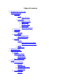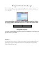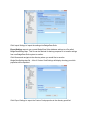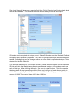
1
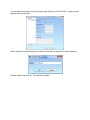
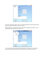
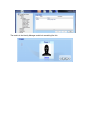
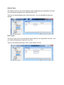
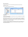
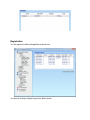
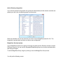
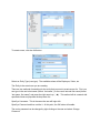
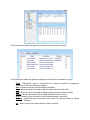
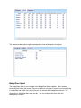
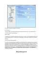
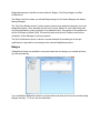
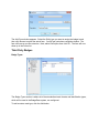
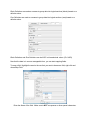
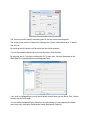
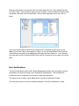
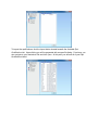
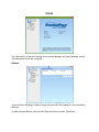
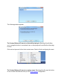
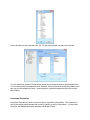
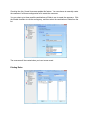
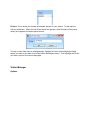
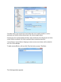
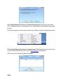
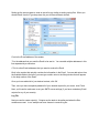
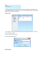
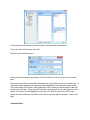
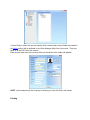
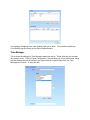
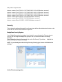
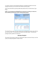
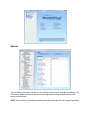
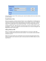
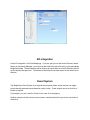
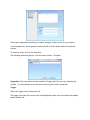
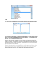
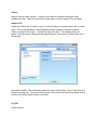
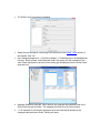
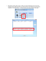
Management Console Users Manual Ver 4.0.3 www.badgepass.com Table of Contents 1. Management Console Login 2. BadgePass System a) Database i. Setup 1. Image Settings ii. List Values 1. Employee Types 2. Image Types 3. Address Types 4. Phone Types 5. States and Provinces b) Campuses c) Schedules i. Holidays d) Registration i. Internet Registration ii. Phone Registration e) Security i. Groups 1. Active Directory Integration 2. BadgePass Security System ii. Users iii. Permissions 3. BadgePass Agent 4. Badge Management a) Badges b) Third Party Badges i. Badge Types ii. Field Mappings c) Epic Qualifications 5. Clients a) Identity Manager i. Options ii. Form Layouts iii. Username Generation iv. Printing Rules b) Visitor Manager i. Options 6. 7. 8. 9. ii. Visitor Types iii. Visit Purposes iv. Custom Fields v. Printing c) Time Manager d) Security Access Control a) Options b) Access Groups c) Card Options d) Status Monitor e) Adding a Main/Controller Panel i. Door Configuration ii. Extra Relays f) Adding an Interface Panel i. Enable/Disable a Door ii. Adding a Wireless PIM AD Integration Event System Appendices Management Console Security Login Each time the Management Console is opened, the logged on user must be authenticated. If the currently logged in user on the computer is in the Administrator, Enterprise Admin or Domain Admin group, the Management Console will launch. If not, a username and password prompt will appear: In order to be successfully authenticated and launch the Management Console, the user must be a member of the built-in Administrator security group. The BadgePass system now comes with a default user: Username admin Password admin BadgePass System This section contains the global configuration properties for the BadgePass Suite not specific to any given module or other section. Database The database section is where you can add custom entities, import\export settings, add custom fields to specific entities, set image paths and list values for the Employee, Image, Address, Phone and State/Province types. . Import Settings: Click Browse and navigate to the BadgePassSettings.bpe file created during a previous export. Click Import Settings to import the settings into BadgePass Suite. Export Settings exports your current BadgePass Suite database settings to a file called BadgePassSettings.bpe. This file can be retained for backup purposes or to transfer settings from one BadgePass Suite system to another. Click Browse and navigate to the directory where you would like to save the BadgePassSettings.bpe file. A list of Custom Card Settings will display showing you which properties will be exported. Click Export Settings to export the Custom Card properties to the directory specified. Setup The setup section contains entity type specific properties. An entity is basically a person or type of person or a place/location. Each entity type has a Name, Description, Standard and Custom Fields, and Image Settings properties. The entity type’s name and description are self-explanatory. The entity type’s Standard and Custom Fields properties are all the properties available to an entity. Click Add to create another entity. The new entity will appear in the window as shown. It is important to remember that for custom entities, the Description column specifies which extra entity table in the database the custom entity will be connected to. Click View / Modify for the selected entity type under the column Fields. Each entity comes with a list of Standard Fields. These fields are not editable except for the ability to set the ID Number and the Birth Date fields to be unique and required. You can add Custom Fields as needed. One example of a custom field could be the company name of the visitor. The process of how to do this will be explained in this section. Since Last Name will always be a required field, the Field is Required and Unique check box is checked and disabled. This indicates that Last Name is always required and unique. ID Number can be required and unique, or not. Select ID Number from the Standard Fields list will display the ID Number’s properties. The Field is Required and Unique checkbox becomes enabled, indicating that you can change whether or not the field is required and unique. This is also true for the Birth Date field. If you choose IDNumber for your unique identifier, you can select the option for Auto Generate ID which will allow the BadgePass system to generate and assign an id number to each new entity of this type. After checking the option, you can set a start number. This is the number that the system will start generating numbers from, and it will go up 1 each time an entity is added. For example, if you set the start number to 1000, the first entity you add will have an id number of 1000. The next will have 1001, then 1002, etc. You can add custom fields for an entity type by right clicking on Custom Fields. A pop-up menu appears with an Add option. Select Add and a window asking you the Name of the field you would like to add is displayed. Provide a Name and click OK. The new field is added. A custom field can be configured as Text, Number, or Date. It can also be given restrictions that determine the minimum and maximum allowed values. These settings determine how the user of the BadgePass Client will see the field and what data the field will accept as valid. Next, you can set the field as a list. This option will allow the user to choose from a preset list of values for this field when a visitor is added or edited. To set a field as a list, click the Create List checkbox. Then click the Add button under Add List Items. This list can either be text or numeric. Now, when a user adds or edits a visitor, the custom field will show up as a drop down list with the preset companies available for the user to choose. Right clicking on the new field will bring up the pop-up menu again with new options. You can also click the buttons at the bottom of the screen. The Custom Fields can be created under a parent element. For instance, you could have a parent element called Sales Person’s Name with fields for First Name and Last Name. NOTE: Parent elements such as Fathers Name are not fields. Only the child elements such as First Name and Last Name are fields. **CAUTION: If you change the name of a custom field that has already been created and has data in it, IT WILL DELETE THE EXISTING DATA!!! Image Settings BadgePass does file based imaging only; it will not accept OLE or BLOB type images. The entity type’s Image Settings properties are for setting the storage location and file type for the entity’s image. Click View / Modify for the selected entity type under the column Image Settings. This will display that entity type’s Image Settings. Select a Base Directory where the entity’s images will be saved and the Image Format you want to save the image as. You can use UNC naming conventions. (Ex: \\<server name>\<folder name>) List Values Employee Types The Employee Types is a list of all the different types of employees your organization can have. How you decide to categorize your employees is up to you. For instance, you could categorize your employees as Full-Time and Part-Time. Click Add, Edit, or Delete to perform the respective action for an Employee Type. NOTE: The same actions (Add / Edit / Delete) are available for all List Types. Image Types The Image Types is a list of all the different types of images your organization can have. How you decide to categorize your images is up to you. If you want multiple image fields in your client, this is where you add the different image types. (Ex: Adding Photo 2 would give you a second image field in the Identity Manager.) Click Add, Edit, or Delete to perform the respective action for an Image Type. The results in the Identity Manager would look something like this: Address Types The Address Types is a list of all the different types of addresses your organization can have. How you decide to categorize your addresses is up to you. There are two default address types: Work and Home. You can add additional values as needed. Phone Types The Phone Types is a list of all the different types of phones your organization can have. How you decide to categorize your phones is up to you. There are four default phone types: Work, Home, Mobile, and Fax. States and Provinces The State and Provinces is a list of all the different types of states and provinces your organization can have. There are multiple default States and Provinces. Campuses Campuses are logical descriptions of locations which can then be subcategorized into buildings and areas within the buildings. By default there is one campus: Main Campus. How an organization chooses to logically break apart its physical locations is up to them. Locations could refer to buildings or areas within the highlighted campus. You can further expand your locations list by right clicking on the hierarchy and adding more locations within the campus. For instance, the following organization has a Main Campus which is then subcategorized into Front Office and Back Office. Additionally, Front Office has the sub-locations of Principal’s Office and Counselor Offices. To add locations, right click on the heading you want the location to be under and choose Add. Another way is to click on the heading and click the Add button at the bottom of the Locations list. Type a Name and Description for your location. You can also move the locations up and down in the list to change the order. Do this by clicking on the + and – buttons on the right side of the box. Schedules This is where you will set all the schedules that will be used in the BadgePass modules. Always and Never are installed by default. You cannot change the start and end times for them. They are primarily used for when someone will have full access or when someone will not have access at all. A schedule is used to establish when someone is able to enter and exit doors, for example, or when someone is allowed to clock in for work. You will set up a Schedule first and then add Time Intervals to it. To create a schedule you first click Add. The following window will appear. Name the schedule and click OK. It will appear in the Schedules window. Highlight the new schedule and the Add button will become active in the lower window for Time Intervals and Holiday Intervals. Click Add under the Time Intervals list and the following window will appear. This is where the start and end time is specified as well as the days of the week that the schedule is to be active. The OK button will not become active until you select a day for the schedule to be active. The time schedule will appear in the Time Intervals list. You can also specify different intervals for a schedule when it is a holiday. The Holiday Intervals will override the Time Intervals on days that are holidays. If no holiday intervals are set up, the schedule will become inactive on holidays. To add a holiday interval, click Add below the Holiday Intervals list. You will see this screen: The time interval you set here will be the time that the schedule IS ACTIVE. For example, the schedule, Business Hours, is used for Auto-Unlocking an Access Control door. On Christmas Eve we have designated a holiday of type Half Day. So on December 24th, the door will be unlocked from 8:00 AM to 12:00 PM instead of regular Business Hours. Holidays You can set up exceptions to routine schedules for holidays. This will override which ever schedule is currently active. You can use this for regular holidays (Thanksgiving, Christmas) or for specific business holidays (Spring Cleaning Day) as needed. To set up a holiday, you will need to create a holiday type first. A holiday type is just a way to categorize your holidays. An example of a holiday type would be a whole day holiday or a half day holiday. Add a holiday type by clicking Add under the Holiday Types list. Enter the Value and Description and click OK. To change the existing holiday type, click the Edit button. To remove an existing holiday type, click the Delete button under the holiday type section. Next you can create a holiday. Click Add under the Holidays list. The following screen will appear. Give the holiday a Name. Then set the day and date. To set the day and date click on any of the date fields in the control and use the up and down arrows to change the values. The Duration field is for setting how many days the holiday will last. If the holiday is only one day long then the duration should be set to 1. If the holiday lasts for 2 days the duration will be set to 2. The holiday types that were setup previously will show up in the drop down list. Select the appropriate type and click OK. The holiday will appear in the Holidays list. Registration You will register the different BadgePass modules here. You start by clicking the Begin Registration Wizard button. This gives you a choice of Internet Registration or Phone Registration. Internet Registration When you click on Internet Registration you will see this screen: Fill in the blanks and click Next. You will see the Internet Registration Progress screen. When the BadgePass Server authenticates the client you will receive a registration code back automatically. Click Done. Phone Registration When you click on Phone Registration you will see this screen: Simply call the number and give them the Customer Code and they will give you back an Unlock Code to type into the next screen. NOTE: The Customer Code shown above is for demonstration purposes ONLY. Enter the Unlock Code into the next screen. (You will have an input box for each module you install) The message Registered with # Licenses will appear as soon as you enter the Unlock Code. Click Done. You will then see the number of licenses In the Installed Products screen. You are now finished with registering the products. Security Groups You can either choose to create BadgePass security groups or use existing Microsoft Active Directory. Active Directory Integration If you click the Add AD Group button the system will automatically find the domain controller and present you with a list of available groups from that server. Select the checkbox next to the ones that you wish to use for BadgePass and click OK. The integration is group-based and does not require user configuration. BadgePass Security System If your BadgePass system is not going to leverage an existing Active Directory domain or Novell E-Directory service, you can use the integrated BadgePass groups to set up user authentication and assign privileges. To add a BadgePass Group, begin by clicking on the Add BadgePass Group button. You will get the following screen: Fill in the Name and Description (optional) and select the Group Type. If you are using a BadgePass group, the Member Of area will appear at the bottom of the window. Users To create a user, click the Add button. Select an Entity Type (user type). The available values will be Employee, Visitor, etc. The Entity is the actual user you are creating. There are two methods of searching for the entity that you want to create a user for. First, you can type in the user’s last name (format: “last name,”) or the user’s last and first name (format “last name, first name”) and press the right arrow key ( ). This method will do a search with specified criteria and populate the drop down list. Specify a Username. This is the name the user will login with. Specify a Password and then confirm it. At this point, the OK button will enable. The user’s password can be changed by right clicking on the user and select Change Password. You will now need to add the user to an existing group. Click the Add button in the Member Of section, found below the Users section in the right pane. Place a check mark beside each group you want to add that user to. Permissions You will assign privileges to groups for the product modules, each entity within the modules, and the user actions within the modules. The Products tab is where the rights are assigned to each module for a group. The Entities tab is where the rights are assigned to entities within a module for a group. Entity – Represents a type or classification of an identity, whether it is employees, students or in the future possibly packages. View – Allows the group to see the entities information Add – Allows the group to be able to add new information about the entity. Edit – Allows the group to be able to change existing information about an entity. Delete – Allows a group to be able to delete information about an entity. Print – Allows a group to be able to send cards and badge to the printer Security – Allows the group to be able to enter data in the security section in Identity Manager. All – Allows a group to be able to do all the above functions . The Campuses tab is where rights are assigned to view each campus for a group. BadgePass Agent The BadgePass Agent is now included in the BadgePass Server Installer. This is another service that will run on the server. There is no option to not install it, however you can set its log in credentials from within the installer like you can with the other BadgePass services. The Agent will run scheduled tasks once per day. You can configure this from within the Management Console. The Agent currently can perform 3 functions: Auto Checkout If this is enabled, once per day the Agent will check out every Visitor ( only visitors ) who is currently checked in to any campus. Expire Cards This will set any card whose expiration date is past to in active. This will deactivate them in the Access Manager system ( removing all access rights ) and will also be reflected in the Identity Manager. Active Directory Synchronization If you are using Active Directory integration, then this will run the synchronization process that will make sure the BadgePass data matches the Active Directory data. When you check to box to enable Active Directory Synchronization, you will be prompted with a message to let you know that you will need to change the logon permissions of the BadgePass Agent before it will perform active directory sync. You must change the log in for that service from Local System to a specific user. You must now give a group that this user is a member of, the 'Replicating Directory Changes' permission to the desired Active Directory partition, using ADSIEDIT on a valid domain controller. Badge Management Badge Management is divided into three sections: Badges, Third Party Badges, and Epic Qualifications. The Badges section is where you will add Badge designs for the Visitor Manager and Identity Manager badges. The Third Party Badges section is where custom cards may be added and setup for use in the BadgePass system. Also, standard card (Driver’s License, Military ID, and Credit Card) data may be manipulated in order to produce a non-standard result. An example of this would be to set the ID Number to [Blank Field]. This would be done so that the ID Number would not be collected in Visitor Manager for privacy purposes. The Epic Qualifications section is where a comma delimited file containing all of the epic qualifications is imported for use throughout the various BadgePass products. Badges If BadgePass Studio was installed in connected mode then the designs you created will show up here automatically. If you installed the BadgePass Studio in unconnected mode then you will need to add the badge designs manually. To do so, click the Add button. The Add Form window appears. Select the Entity type you want to assign the badge to and then click Browse to select the actual form. You will get a windows navigation window. The form will have an xps file extension. Next, add a Description then click OK. The form will now show up in the Forms list. Third Party Badges Badge Types The Badge Types section is where all of the standardized card formats and identification types, which will be used in the BadgePass system, are configured. To add a custom card type, click the Add button. Next, check the Use Card Reader checkbox (this enables the card reader in the BadgePass system) and the Auto-Detect checkbox (this lets BadgePass automatically find the reader on the system). To verify that the card reader is functioning properly, click the Start Test button and swipe a card. (You must click the Stop Test button before closing the Card Reader Setup window.) The following window will appear when you click the OK button on the Card Reader Setup window. Enter a Name for the custom card type and swipe a card. In order to be able to set up fields, we must first parse the card data into blocks and rows. This is accomplished via Block Splits and Row Splits. Block Splits are achieved by specifying delimiter values used to separate Blocks. Row Splits are achieved by specifying delimiter values used to separate Rows. Block Delimiters are used as a means to group data into logical sections (blocks) based on a delimiter value. Row Delimiters are used as a means to group data into logical sections (rows) based on a delimiter value. Block Delimiters and Row Delimiters can be ASCII or Hexadecimal values. (Ex. 0x0D) Now that the data is in a more manageable form, you can start mapping fields. To map a field, Highlight the area in the row that you want to become a field, right click and chose Map Field. Enter the Name of the field. Make sure to NOT use spaces or other special characters. The Column is used to specify the starting point in the row to start extracting data. The Length is the number of characters, starting at the Column value defined prior, to extract from the row. By checking the All checkbox, all data from the row will be extracted. You can also separate blocks into more rows by using a Row Delimiter. By selecting the Go To button or clicking the Go To menu item, focus will be placed on the Block\Row of the highlighted field under Mapped Fields. If you click on a Mapped field, you will see a balloon that will show you the Block, Row, Column location and the field Length. You can delete a mapped filed by selecting it by right clicking on it and selecting the Delete menu item or by clicking the Delete button under the Mapped Fields list. In order for BadgePass to be able to distinguish this card type from any others, you MUST create a Rule. To create a rule highlight a section of data that will ALWAYS be the same and unique for this particular card. Next, right click and choose Map Rule. Verify that the information is correct and click OK. Field Mappings Now you must map the new Card Fields to the Entity Fields so that when a card is swiped BadgePass will know where to send the data. BadgePass comes with a set of default mappings that you will see when you select the card type from the drop down list. The default mappings are all that is needed to use all of the standard cards. However, if you have added custom fields or if you have added a custom card. You will need to add new field mappings for the new items. Begin by choosing the new card from the Card Fields drop down list. Next, highlight the field you wish to map. Then choose the entity you wish to map to, select the field you want the data to populate, and finally click the Map button. The new field mapping will show up in the list below. If you do not want a field (ID Number for example) from a standard card (Driver’s License, Military ID or Credit Card) to be mapped to a field, you can and select [Blank Field] under the Card Fields list and map it to the appropriate field under the Entity Fields list. In our example, the information from the ID Number field from the driver’s license will not be saved in the visitor table. Epic Qualifications The Epic Qualifications section under Badge Management is where you can import a comma delimited file (csv file) that contains your desired Epic Qualifications. The Available Epic Qualifications list is comprised of two columns: Name and Description. The Name column is where a short abbreviation of the Epic Qualification is listed. The Description column is where a detailed description of the Epic Qualification is listed. To import the qualifications, click the Import button located beneath the Available Epic Qualifications list. Upon clicking you will be presented with an open file dialog. From here, you can navigate to your desired csv file and click Open. At this point you will see all of your Epic Qualifications listed. Client The Client section is where the settings for the Identity Manager, the Visitor Manager, and the Time Manager modules are configured. Options Custom Buttons’ Mappings is where custom event buttons will be added for use in the Identity Manager. To add a custom Button, click on Add. Give the button a name. Click Next. The following window appears. The Custom Button will execute a client defined plug-in: Selecting this will allow you to assign the button to an external .exe or other program from within the client plugin setup Click next and proceed to the client context menu. Select to finish configuring the event. The Custom Button will execute a custom event: Selecting this will cause the button to run an event that has been set up in the Event System configuration. Click next and the following window will appear. E-Mail Setting up the event system to send an e-mail is very similar to setting up log files. When you choose Email from the Type drop down list you will have different choices. From is the E-mail address of the sender. To is the address that you want the Email to be sent to. You can add multiple addresses in this line separated by a semicolon. CC is for other Email addresses that you want to receive the Email. Body is the section that actually contains the information in the Email. You can add values from the available fields to the left or you can type a static value in the Body window that will appear in the body section of the Email. Once you have added all of your desired content, click OK. Then, once you have completely added all of your desired outputs for your event, click Finish. Next, you’ll need to make sure to set your SMTP server settings (if you have created any Email outputs for any of your events). Log File Next we need to create output(s). Outputs are the tasks to be performed when the filter conditions are met. In our example we have chosen to create a log file. To create an output click Add. The following screen will appear. Give the output a Name and then select Log from the Type drop down list at the top right. Next we must add the details to the log file. These are the actual values that will be written into the log file. Double clicking the values in the left window pane will generate the necessary coding in the window where the cursor is located. There are several values that need to be set. Since it’s a log file, we will need to set the Directory Path of where you want to save the file. Enter the path in the Directory Path box or click on the button next to the box and select the path. Next name the file in the File Name box. Don’t forget to add the “.txt” or whatever file extension you want to use. Putting a check mark in the Append If Exists check box will cause the new log entries to be added to the existing file instead of overwriting the existing data. If you expand the menus in the left pane you can double click on a value and it will place the code in the Content pane. This is how you add data into the log file. Click on the New Line button when you have all the data you want in the Content window. This will cause each entry in the file to have a carriage return/line feed and the end of the record. Once you have added all of the desired content, click OK. Form Layouts The Form Layouts section is where you select the fields that you would like to appear in the Identity Manager Production screen. Select the Entity from the drop down list. The Identity Manager Production screen is divided into two columns. Select Add under the left or right column depending on where you want the field to be. The Add Items screen will appear. Select the field you want and then click OK. Do this for each field you want in the column. You can specify an Operator Prompt which is what the end user will see on the production form. You can also set the field properties to be Required, Read Only and Searchable by checking the box next to each respective choice. Leaving the box unchecked means the field will not have that attribute. Username Generation Username Generation is used to create an entity’s username automatically. The username is sent to the access control panels and is used to identify an entity in the panels. It is also used to log into the BadgePass system modules and Monitor Pointe. Checking the Auto Create Username enables this feature. You can choose to manually create the username if all three contingencies fail to create the username. You can select up to three possible combinations of fields to use to create the username. Click the Enable checkbox to use the contingency, and then select the combination of fields from the list. The username will be created when you insert a new record. Printing Rules Printing Rules is where you establish the printing behaviors for the Identity Manager. Select the Entity from the drop down list at the top. The Control Field is a way to determine which badge and printer are used based on a value in the field. The Print All option will cause all rules that are true in the Value list for your Control Field to be printed automatically, if there is more than one rule that is true. Ex. Campus Membership is your Control Field, and the Employee that is being printed has more than one campus membership. The Allow User Selection option will cause all the badges for all of the rules that are true, to be listed in a user dialog for the user to select which Badges they want to print. Values: These are the literal values that could show up in the Control Field. For example if the value of Employee Type is Administrator, then the Employee card will print. To add a value, click the Add button. A list of available Values will appear if it’s a list type field. However, if the Control Field is a simple text field, then just enter the value into the box. The choices in the drop down list next to the Value you have created, determine whether the Badges mapped to that value will all be printed or the user will be prompted to select a badge(s) to print. Badges: These are the badge designs available for printing. These show up after you save them in BadgePass Studio (in connected mode) or after you import the design in the Badges section under Badge Management. The badges listed here are entity specific so you will only see the badges for the chosen entity type. Printers: This is where you will add the available printers on your system. To add a printer, click the Add button. When the Add Printer Name box appears, enter the Name of the printer exactly as it appears in windows printer section. To map a control field Value to a Badge design, highlight the Value then highlight the Badge design you want to print then click on Map under the Badges column. Then Highlight the Printer you want to print to and click on Map again. Visitor Manager Options The Which Entity Types should Auto-Load? allows the user to specify whether or not the employees and custom entities will pre-load in the visitor manager screen. Checking the Auto Load box beside the Entity Types will allow the list of Employees and other custom entities to preload in the visitor manager screen to speed up searching. Custom Buttons’ Custom Buttons’ Mappings is where custom event buttons will be added for use in the Visitor Manager To add a custom Button, click on Add. Give the button a name. Click Next. The following window appears. The Custom Button will execute a client defined plug-in: Selecting this will allow you to assign the button to an external .exe or other program from within the client plugin setup Click next and proceed to the client context menu. Select to finish configuring the event. The Custom Button will execute a custom event: Selecting this will cause the button to run an event that has been set up in the Event System configuration. Click next and the following window will appear. E-Mail Setting up the event system to send an e-mail is very similar to setting up log files. When you choose Email from the Type drop down list you will have different choices. From is the E-mail address of the sender. To is the address that you want the Email to be sent to. You can add multiple addresses in this line separated by a semicolon. CC is for other Email addresses that you want to receive the Email. Body is the section that actually contains the information in the Email. You can add values from the available fields to the left or you can type a static value in the Body window that will appear in the body section of the Email. Once you have added all of your desired content, click OK. Then, once you have completely added all of your desired outputs for your event, click Finish. Next, you’ll need to make sure to set your SMTP server settings (if you have created any Email outputs for any of your events). Log File Next we need to create output(s). Outputs are the tasks to be performed when the filter conditions are met. In our example we have chosen to create a log file. To create an output click Add. The following screen will appear. Give the output a Name and then select Log from the Type drop down list at the top right. Next we must add the details to the log file. These are the actual values that will be written into the log file. Double clicking the values in the left window pane will generate the necessary coding in the window where the cursor is located. There are several values that need to be set. Since it’s a log file, we will need to set the Directory Path of where you want to save the file. Enter the path in the Directory Path box or click on the button next to the box and select the path. Next name the file in the File Name box. Don’t forget to add the “.txt” or whatever file extension you want to use. Putting a check mark in the Append If Exists check box will cause the new log entries to be added to the existing file instead of overwriting the existing data. If you expand the menus in the left pane you can double click on a value and it will place the code in the Content pane. This is how you add data into the log file. Click on the New Line button when you have all the data you want in the Content window. This will cause each entry in the file to have a carriage return/line feed and the end of the record. Once you have added all of the desired content, click OK. Use Campus Filtering causes all searches done in the Visitor Manager, to be filtered by the Campus Membership of the visit contact. The Visit Contact must be a member of the Campus that the Visitor Manager was installed at. Visitor Types Visitor Types are a way to categorize individuals that visit entities and locations. (Ex. Parent, Service Technician, Vendor). To set up a Visitor Type, click Add. Enter the Value and Description. Visit Purposes Visit Purposes are the reasons a visitor would be visiting entities and locations. To set up a new Visit Purpose, click Add. Enter the Value and Description. At this point you will need to associate a Visit Purpose with a Visit Action and a Visit Contact type. Each visit purpose will be individually associated with a Visit Action and a Visit Contact type. To map these values, highlight the visit purpose then highlight the visit actions that apply to that visit purpose then click on Map. Next highlight the Visit Contact type that will apply to that visit purpose and click Map. If you would like to map the visit purpose to more than one visit action and/or visit contact you will highlight the value in the list, hold the control key (CTRL) and choose the other values you would like to also like to associate with the purpose. Finally, click Map. Custom Fields Custom Fields is where the user can specify which custom fields (custom fields are created in the Setup section) will be available in the Visitor Manager Add Visitor Info screen. They also show up in the Edit Visitor Info screens. Place a check mark next to the custom fields you would like to be visible and editable. NOTE: In this example only the Company is showing up in the Add Visitor Info screen. Printing Form: Indicates the form to print. If Allow User Selection is selected, the user will be presented with a drop-down box to choose their form at the time the form is printed. Printer: Indicates the printer to use to print the form. If Allow User Selection is selected, the printer dialog box will be presented to the user at the time the form is printed. If Use Named Printer is selected, then a text box will appear asking for the printer’s name. NOTE: If using Use Named Printer, the name MUST be exact. If the printer is not found, then the printer dialog box will be presented to the user at the time the form is printed. Your settings will appear in the main window when you’re done. You can edit or delete the Form Defaults just by clicking on the Edit or Delete buttons. Time Manager This is where the settings for Time Manager exports are set up. These will allow you to export time cards to a file. Click on Export Configuration. This will allow you to pick which fields, along with the delimiter that will be written to the export file that is created from within the Time Management Console. A setup like this: Will produce output like this: hudson, summer;True;3/7/2013 4:17:07 PM;3/5/2013 3:12:44 PM;hudson, summer;1 hudson, summer;True;3/7/2013 4:17:07 PM;3/5/2013 3:46:51 PM;hudson, summer;1 hudson, summer;True;3/7/2013 4:17:07 PM;3/5/2013 4:58:56 PM;hudson, summer;1 hudson, summer;True;3/7/2013 4:17:07 PM;3/7/2013 1:40:45 PM;hudson, summer;1 hudson, summer;False;;3/8/2013 12:00:00 AM;hudson, summer;0 hudson, summer;False;;3/9/2013 12:00:00 AM;hudson, summer;0 hudson, summer;False;;3/14/2013 12:00:00 AM;hudson, summer;0 Security This is where the settings that specify how the end user will be authenticated and how he or she will be able to use the client modules are specified. BadgePass Security System If your BadgePass system is not going to be installed on an existing Active Directory domain, you can use the integrated BadgePass groups to set up user authentication and assign privileges. Select BadgePass Security System and click on the Set Security Type button. Highlight the group and assign privileges accordingly. NOTE: If you already have the Activity Directory Security type chosen it will delete the settings. Active Directory Integration If you plan to connect to an existing Active Directory to authenticate groups for the visitor manager module then you will use the Active Directory Security setup. Click on the Active Directory Security radio button and then click on the Set Security Type button. NOTE: If you already have the BadgePass security type set up and you choose the Active Directory security type, all your settings will be deleted. The Active Directory groups that were selected under the BadgePass security setup will show up in the Groups box. You can set the user actions in the lower window. This will be the privileges that are granted to the client user. Access Control The Access Control section is where you configure the Options, the Access Groups, the Card Options, and setup the panels for Access Control. Options The Log Debug Information check box is for creating a debug log file for support purposes. This will create a support file that can be sent to the support group to help analyze issues in the access control system. NOTE: Only check the Log Debug Information box under the supervision of a support specialist. The Use for Entity Tracking check box is for telling the Access Control server whether or not to let the visitor managers know if someone changes locations by scanning their card on an access control reader. In the Transactions section you can record all or some of the transactions within the access control system. Place a check in the box next to the transaction to would like to save. Card Formats Click on Card Formats to set up the parsing of cards that will be used in Access Control. By default, there are 3 card formats: Magnetic Card, Prox 26 Bit, and Xceed 40 Bit. Each card format will have a number of bits and a facility code (-1 if not using facility codes) along with other parameters. You can Add, Duplicate, Edit, and Delete card formats from this area, and the changes will be automatically updated in the panels. If you want to trigger a manual update of all card formats in the panels they are used in, click the Send To Panels button. To edit an existing card format, such as when changing the facility code, click the Edit button. The edit panel will become visible: Change any parameters and then click Save. If this card format is currently in use in any panels, it will be automatically updated in the panel when you save it here. Click Duplicate if you want to create an exact copy of the selected card format. This is useful in the situation where you have two different facility codes for prox cards (15 and 197 for example). You would click on the default Prox 26 Bit card format, enter 15 for Facility Code and click Save. Then click on Prox 26 Bit card format and click Duplicate. Then enter 197 for Facility Code and click Save. Door Groups Click on Door Groups to set up functional groups of doors in Access Control. They can be used for lockdowns and for auto-unlock features. Click the Add button to add a new door group. Enter a name (Outside Doors for example) and click OK. You can edit the group name by clicking Edit, or delete the group by clicking Delete. To include a door in the group, click the check box next to its name in the tree view on the right: To set up Auto Unlock for this group, choose a schedule from the drop down list. Each door in the group will then be unlocked during the time that the schedule is active. If you would like the doors to only be unlocked after a valid card read during the schedule, click the Require Valid Card Read check box. When this option is in use, if a valid card read is registered on one door in the group during the schedule, then all the doors in the group will then be unlocked. To allow the group to participate in lockdowns, check the box for Enable Lockdown. If this option is checked and 3 valid card reads occur for a card that belongs to an entity in an access group that is designated for Campuswide Lockdown on the Access Groups set up, then every door in that group will be locked. The doors will continue to allow request to exits, but no access will be granted to any card, and any unlocked doors will be locked. When a group is in Lockdown Mode, a button will be visible. Click it to return the doors in the group to normal operations. Access Groups Click on Access Groups to set up who has access or permission to use doors in the Access Control system. You will see a list of your available groups in the left side list. These by default will be your BadgePass groups that were set up earlier under BadgePass System -> Security. If you prefer to use LDAP groups and have obtained the necessary support to set up LDAP integration, you can check the box for Use LDAP groups. Then the list will contain only the LDAP groups. You can set up a different set of permissions for each group. A user is assigned permissions based on the permissions of the groups they are a member of. You assign groups privileges to enter doors in the Door Rights section on the right. Click on the group you want to grant privileges to and select the appropriate value in the drop down list next to the door. The Use for Quick Pass check box allows for the associated group(s) to be available for use with QuickPass. This group(s) will represent the door privileges that a QuickPass holder will have. If more than one group is selected for QuickPass use then in the BadgePass Client screen a drop down list will show up under the Define Visit section. Then the user can pick which group the QuickPass card will use for determining privileges when they check in the visitor. If only one group is designated for Use for QuickPass, the drop down list in the BadgePass Client will not appear and all QuickPass cards will automatically be assigned the permissions of that group. The Campuswide Lockdown check box allows for an entity that is a member of the associated group(s) to be able to enact a lockdown of a door group by registering 3 successful reads of their card. Card Options Card Options is where you set the association between the Entity Type (Employee, Visitor, etc.) and the Card Data Types. For example the employee’s card may have the data that will be used to open the doors in a MOCA sector, but the visitors cards may use the information stored in Mag Track 2. This tells the Access Control system which field to pull the information from and send to the panels for verification. Once all the panel hardware has been installed and networked together, you need to configure them in the BadgePass Management console. Status Monitor The Status Monitor is where you can get information about the control panel that are installed on your system. Adding a Main/Controller Panel (BP-1502, BP-1501, BP-2500) The BP 1502 panel comes standard with 2 doors. Each door comes with 1 extra output relay. You can add more doors by adding interface panels. This is discussed later in the manual. Also available are the BP-1501 which is an Ethernet based controller panel and the BP-2500 which is used with the wireless doors and elevator setup. Start by right clicking on the campus name and choose Add. The configuration window will appear. Choose the Model of the panel from the dropdown list and then select the Template. The template is the pre-designed configuration of the panel. It represents how the hardware is wired and how the doors and relays, etc. are used. Under Manage, change the Name of the panel to be more descriptive of the location of the panel so that when you are looking at all the panels in a list it will be easier to select the one you need to work with. Set the IP Address of the panel. Optionally, you can select the Campus Location of where the panel will be installed. This is only for auditing or to help a user determine where the panel is located. If you are using a card type that has a facility code you can enter it in the Facility Codes box. The General Input Setup section is where you define how the extra inputs on the board will behave Your choices are: Open – Unsupervised: The input is expecting a normally open state. A contact close will change the input state. Closed – Unsupervised: The input is expecting a normally closed state. A contact opening will change the input state. Open – Supervised: A supervised contact state means that the input is expecting to see a certain resistance (normally a 2K Ohm resistance) on the input. When the resistance value changes the input will change the input state. Closed – Supervised: A supervised contact state means that the input is expecting to see a certain resistance (normally a 2K Ohm resistance) on the input. When the resistance value changes the input will change the input state. When you click on Save the Panel will reset. If you are in an area that does not use Daylight Savings time then un-check the Use Daylight Savings Time box. You can also monitor the activity on the panel. Click the Show Activity button. This will show the activity from the panel in the list above the button. If you are troubleshooting with support or need to see debugging messages, you can click the Show Advanced checkbox. This will only show the debugging messages if the Log Debugging Information box is checked on the Options screen. Door Configuration If you click on the door you will get the preceding screen. This is where you can configure special events for the door as well as lock or unlock the door manually. You also set the behavior of the extra output relay. The extra output relay can control different things such as turning on a light or sounding a buzzer. You can also choose whether or not to use the Enforce Door Position Logic feature. When enabled, this will tell the panel to report a card read or a REX event either after the door position changes state or the Unlock Time expires. Additionally it can ignore those and send it immediately. The Silent REX, if it is selected, causes the REX signal to not fire the relay. You can also enter an install note in the Install Note field. This is primarily used for installation and service personnel as it helps correlate the doors to the construction plans. You should name the door to be more descriptive under the Door Name field. The Unlock Time is how long the door stays unlocked after it has been unlocked. The Reclose Time is how long after the door is opened that the door has to be closed before a held open alarm is sent. Disable Door Forced tells the software not to send an alarm, if the door is forced open. Disable Door Held will cause the software not to send an alarm if the door is held open too long. Checking the Require Valid Card Read box causes the Disable Door Forced and Disable Door Held not to activate until a valid card has been read at the door reader during the specified schedule. For example, you can set the door to Disable Door Forced during business hours from 8-5. However you do not want the door to disable the door forced alarms until the first person arrives in the morning and reads a valid card. The Location will set the value for entity tracking to reflect the location that the entity will enter when leaving the current location. The Authentication Type tells the access control system how the user will authenticate to gain access. The Card Only option means the user will only be able to use a card to authenticate to the access control system. The Pin Only option means the user will only be able to enter a pin number on a keypad to authenticate to the access control system. The Card and Pin Required option means that a user will have to have to present a card to the reader as well as enter a pin number on a keypad. The Card or Pin Required option means the user can either present a card to a reader or enter a pin number on a keypad to authenticate to the access control system. The Reader Format can be set to Wiegand, Magnetic, or Advanced depending on what type of cards you will use and what type of readers are installed. Wiegand is the default. If you are not using Wiegand and you choose Magnetic or Advanced, you will need to contact support for information about how to get your card format setup and what value is required for the Advanced option. You can also set the keypad mode for the reader. These are industry standard options that configure how the keypad data is sent from the reader. The Strike Mode is now available to be set from this setup screen. There are 2 modes: 1. Open -- deactivates the strike when the door opens. This means if there is no door position switch or the door was already open the strike will open, then immediately close. ( this is the default ) 2. Closed – deactivates the strike when the door closes. If there is not a door position switch or the door is already open, then the strike will still stay open for the entire unlock time or until the door is closed. Extra Relays The extra relays (Relay 2, 4…) can be used for various things. You can cause a light to turn on or you can cause a buzzer to go off or any number of other things as needed. The mode sets when an extra relay engages. Selecting event means that some type of action has to happen for the relay to engage. The choices include a door being forced open, a valid access, a request denied, a door help open too long or a request to exit. The delay time is how long after the event occurs before engaging the relay. The energize time is how long the relay will stay engaged. You can also set the relay to engage on a schedule. Select schedule from the dropdown list and select one of the pre-set schedules. You can configure a schedule under the schedules section in the BadgePass Management Console. Click Enable to use the relay. If you select Follow then the extra relay will mimic the actions of the strike relay. This is only available on the first extra relay if more than one is available. Adding an Interface Panel (BP-52, BP-51e, PIM Module) The BP-52 Interface panel comes standard with 2 doors and 2 extra relays per door. To add a BP-52 interface panel, right click on the BP-1502 panel that the interface panel will be connected to and select Add Interface Panel. You will see the following configuration screen. Under the Configuration section you will choose the Model of the interface panel. As new models come available they will show up in the list. Choose the Template. Currently only Standard 2 Door templates are available. Next, under the Manage section, set the Address of the interface panel, this is determined by the dip switches on the BP-52 panel. You can set the location of the panel also. This step is optional. The configuration of the specific doors on the interface panels is the same as it is on the main/controller panel doors. Each type of hardware will have a different number of extra relays available. The BP-51e is an interface panel that is connected to the main board through Ethernet. After clicking Add Interface Panel, choose BP-51e under model. The address for this type of panel should always be 0. You can set a location if desired. Enter an IP Address that you would like to assign to this panel, and enter the MAC Address that can be found on a sticker on the panel itself. If you are using Ingersoll-Rand Wireless doors with the BP-2500 controller panel, you can choose PIM Module under model. For this type of panel, the address should be set to the address of the PIM that has been configured with the hand held device. For the Assa Abloy Aperio 8 Door Interface panel, match the address with the one that is set by the DIP switches. Enable/Disable a Door Each door represents a session for Access Control. As you add hardware in the Management Console, the doors that you add will take a session if one is available. If you are not using one of the doors on a panel and wish to release that session for use by a different door, you can disable it. Simply right click on the door and click Disable. You will no longer be able to use or manager that door at all. Now right click on the door that you want to use the session for and click Enable. This will use the session for this door and allow it to be used and managed in the BadgePass Access Control system. Adding a Wireless PIM Before you add the wireless PIM (Panel Interface Module) you must have a model 2500 controller. The PIM will not work with the other controllers. You must also connect the RS485 connection to port 3. Right click on the Controller in the management console tree and select Add Interface Panel. Choose the PIM from the interface list, give it a Name and select the RS485 Address from the drop down list. AD Integration Under AD Integration, click Field Mappings. If you are going to use the Active Directory search feature in the Identity Manager, you must map the fields from Active Directory to the appropriate BadgePass fields. These mappings will be used to get information from Active Directory and fill out the Identity Manager form. You should at least map first and last name for the search to be effective. Event System The BadgePass Event System is an asynchronous system where certain actions can trigger events that will generate outputs based on various rules. These outputs can be in the form of Emails or log files. For example, you can e-mail the Onsite List in case of an emergency. Another example would be that you can create a customized log file every time a new visitor is checked in. Events are configurations consisting of a name, a trigger, a filter and one or more outputs. In the example here, we are going to create a log file of all the visitors added at a particular location. To create an event, click on the Add button. The following window will pop up. Give the event a Name. Click Next. Suggestion: The event name should describe the Trigger and Filter, but not necessarily the Outputs. You will possibly have to choose it from a long list of other events later. Trigger Select the Trigger from the drop down list. The trigger is the type of the event within the BadgePass system such as Visitors being added, edited, deleted, etc. Filter The filter is a rule or condition that must be true before the event system executes the output. You can choose a value from the left window by double-clicking it or you can manually type the values of true or false indicating whether or not the event took place. In this example we used the value “True” to indicate that we added a visitor. Note that visitor information is showing up in the left window pane because we chose Visitor Added as our trigger. If we had chosen anything to do with employees then the employee data fields would be present in the left window pane. The same would be true for all other entities and their respective custom data fields. Example: If you only wanted to record a log file for one location then you could choose Source Machine Name (location1 for this example) under the common fields and the event system would only add data to the log file if the machine name matched the name location1. Double clicking on the value in the left window pane will generate the necessary coding in the filter window. Double clicking on Source Machine Name generated the highlighted code below. Then just manually type[space] = [space] name of the computer. [EventSystemEvaluator(Path=SourceMachineName)] = location1 NOTE: It is important to have a space between your comparison symbols (=, <, <=, >, >=) and what your comparing to. If what you’re comparing to has a space in it, then surround it with quotes. For example, if the computer’s name was ‘locaton 1’, then the above expression would have looked like the following: [EventSystemEvaluator(Path=SourceMachineName)] = “location 1” For our example we are just concerned whether or not a visitor was added. In this case we just add the value true. Output Next we need to create output(s). Outputs are the tasks to be performed when the filter conditions are met. There are currently two output types: Log File, Image to File, and Email. Image to File Image to file allows you to create a copy of an entity’s image in a custom location with a custom name. This provides flexibility in how BadgePass exports images to third party systems. Create an Image to File output. To create an output click Add. The following screen will appear. Give the output a Name and then select Image to File from the Type drop down list at the top right. Next add the details. Pick the directory where the output will be written. Give it a file name and choose the image type. The output filed file name can be constructed with the available fields in the box to the left by double clicking on the field. Log File Create a log file. To create an output click Add. The following screen will appear. Give the output a Name and then select Log from the Type drop down list at the top right. Next we must add the details to the log file. These are the actual values that will be written into the log file. Double clicking the values in the left window pane will generate the necessary coding in the window where the cursor is located. There are several values that need to be set. Since it’s a log file, we will need to set the Directory Path of where you want to save the file. Enter the path in the Directory Path box or click on the button next to the box and select the path. Next name the file in the File Name box. Don’t forget to add the “.txt” or whatever file extension you want to use. Putting a check mark in the Append If Exists check box will cause the new log entries to be added to the existing file instead of overwriting the existing data. If you expand the menus in the left pane you can double click on a value and it will place the code in the Content pane. This is how you add data into the log file. Click on the New Line button when you have all the data you want in the Content window. This will cause each entry in the file to have a carriage return/line feed and the end of the record. Once you have added all of the desired content, click OK. E-Mail Setting up the event system to send an e-mail is very similar to setting up log files. When you choose Email from the Type drop down list you will have different choices. From is the E-mail address of the sender. To is the address that you want the Email to be sent to. You can add multiple addresses in this line separated by a semicolon. CC is for other Email addresses that you want to receive the Email. Body is the section that actually contains the information in the Email. You can add values from the available fields to the left or you can type a static value in the Body window that will appear in the body section of the Email. Once you have added all of your desired content, click OK. Then, once you have completely added all of your desired outputs for your event, click Finish. Next, you’ll need to make sure to set your SMTP server settings (if you have created any Email outputs for any of your events). SMTP Settings In order for the Event system to be able to send Emails you must configure the following settings. It should be noted that each network is configured differently. Check with the network administrator to verify that the customer’s mail server will send the e-mails from the event system. SMTP Server: The DNS name of the mail server. Enter the name of the server and click Save. SMTP Port: The port number that the mail server communicates on. Enter the port number and click Save. Username: The username for an authenticated user on the SMTP Server (if necessary). Enter the username and click Save. Password: The password for an authenticated user on the SMTP Server (if necessary). Enter the password and click Save. Make sure you confirm the password by re-entering the password in the text beneath the password textbox. TCP To send data triggered by an event in BadgePass over a data stream to a specified IP Address, use the TCP output type. In the Host field the IP Address of the host that is listening for the data stream should be entered. The Port field should contain the valid port used by the host. *Note that the Event System is robust enough to interpret placeholder values as numbers when the event is triggered, the window defining the output accepts text as a valid port number value (not just numbers). It is up to the BadgePass System Administrator to make sure the text provided is interpretable to a meaningful port number. The content is where the data is entered that will need to be sent to the host. It will have to be in the format required by the host. Appendices Appendix A: Silent Entity Tracking Silent Entity Tracking is the ability to track an entity (other than Visitor) through the Visitor Manager system using the E-Seek reader that is used to check in visitors. We will be using the Employee entity for our example but the process is the same for the Person 1, Person 2, Person 3 entities as well. To begin: In the management console go to Badge Management -> Badge Types Click Add. You will get the Card Reader Setup screen Check the Use Card Reader and the Auto-Detect boxes. If the setup does not find the reader then you can un-check the Auto-Detect box and manually set the reader port. The Define Card Type screen will appear. Swipe the card and parse it according to the directions in the Badge Types section of this manual. Click OK. Go to Badge Management -> Third Party Badges -> Field Mappings in the Management Console. Select custom card (Employee Card in this case) you just created from the Card Fields drop down list and the correct entity type (Employee) from the Entity Fields drop down list. Highlight IDNumber under the Card Fields list and Highlight the IDNumber field in the Entity Fields list and click Map. The mapping will show up in the list box below. (**It is important to note that the employee must exist with that ID Number in the employee table before the Entity Tracking will work). Silent Entity tracking will now work. When you swipe the Employee card in the visitor manager screen, nothing will show up. But if you look in the Onsite List you will see the employee in the Other section. To check this entity out simply swipe the card again.