1
EK-TMBII-OP-OOI
TMB11/TS03
DECmagtape system
user's manual
(TMB11-M system)
digital equipment corporation • maynard, massachusetts
1st Edition, November 1976
Copyright © 1.976 by Digital Equipment Corporation
The material in this manual is for informational
purposes and is subject to change without notice.
Digital Equipment Corporation assumes no responsibility for any errors which may appear in this
manual.
Printed in U.S.A.
This document was set on DIGITAL's DECset-8000
computerized typesetting system.
The following are trademarks of Digital Equipment
Corporation, Maynard, Massachusetts:
DEC
DECCOMM
DECsystem-lO
DECSYSTEM-20
DECtape
DEC US
DIGITAL
MASSBUS
PDP
RSTS
TYPESET-8
TYPESET-II
UNIBUS
CONTENTS
Page
CHAPTER 1
GENERAL INFORMATION
1.1
1.2
1.2.1
1.2.2
1.3
1.4
1.5
INTRODUCTION . . . . .
GENERAL DESCRIPTION
System Configuration
Physical Description .
SYSTEM FUNCTIONAL DESCRIPTION
APPLICABLE DOCUMENTS
.......... .
SPECIFICATIONS
CHAPTER 2
UNPACKING, INSTALLATION, ANP ACCEPTANCE TESTING
2.1
2.1.1
2.1.2
2.1.3
2.2
2.2.1
2.2.2
2.3
2.4
2.5
2.5.1
2.5.2
2.5.2.1
2.5.2.2
2.5.2.3
2.5.2.4
2.5.2.5
2.5.3
2.6
SITE PLANNING AND CONSIDERATIONS
Space Requirements . . . . .
Power Requirements
Enviro nmental Requirements
UNPACKING . . . . . . . . . . .
Cabinet Unpacking Instructions
Device Unpacking Instructions
INSPECTION . . . . . . . . . . . .
CABINET INSTALLATION' - SYSTEM ALREADY INSTALLED
INSTALLATION OF SYSTEM COMPONENTS
TS03 Mounting Instructions .
TMB 11 Installation/Cabling .
System Unit Installation
Module Installation
Unibus Cabling
Slave Bus Cabling
Securing Cables
TS03 Cabling
ACCEPTANCE TESTING .
CHAPTER 3
SYSTEM OPERATING INSTRUCTIONS
3.1
3.2
3.2.1
CONTROL AND INDICATORS
OPERA TING PROCEDURES
Tape Threading
Power Up . . . . . . .
Tape Loading . . . . .
Placing Tape Unit On-Line
Tape Rewind and Unloading
Power Shutdown
.....
3.2.2
3.2.3
3.2.4
3.2.5
3.2.6
iii
1-1
1-1
1-1
1-2
1-6
1-11
1-12
2-1
2-1
2-1
2-1
2-1
2-1
2-3
2-3
2-3
2-4
2-4
2-6
2-6
2-8
2-8
2-8
2-8
. 2-12
. 2-15
3-1
3-1
3-1
3-1
3-2
3-2
3-3
3-3
CONTENTS (Cont)
Page
CHAPTER 4
CUSTOMER CARE AND PREVENTIVE MAINTENANCE
4.1
4.2
4.3
4.3.1
4.3.3
CUSTOMER RESPONSIBILITIES
..................... .
CARE OF MAGNETIC TAPE . . . . . . . . . . . . . . . . . . . . . . . . .
CUSTOMER PREVENTIVE MAINTENANCE OF TS03 TAPE TRANSPORT
General
Preventive Maintenance
Materials Required
APPENDIX A
MAGNETIC TAPE FUNDAMENTALS
A.I
A.2
A.2.1
A.2.2
A.2.3
AA
A.S
A.6
MAGNETIC TAPE FUNDAMENTALS - DEFINITIONS
RECORDING METHODS AND DSCmagtape FORMATS
NRZI Recording Method
9-Channel Tape Format . . . . . . . . . . . . . .
7-Channel Tape Format .. . . . . . . . . . . . . .
CYCLIC REDUNDANCY CHECK (CRC) CHARACTERS
LONGITUDINAL REDUNDANCY CHECK (LRC) CHARACTER
DATA FILES . . . . . .
TRACK ASSIGNMENTS . . . . . . . . . . . . . . . . . . . . .
APPENDIX B
TMB 11-TS03 SYSTEM PARTS LIST
B.I
B.2
TS03 PARTS
TMBII PARTS
APPENDIX C
MAGNETIC TAPE DRIVE CLEANING INSTRUCTIONS
C.l
C.2
C.2.1
C.2.2
C.2.3
C.2A
C.2.S
DIGITAL'S MAGNETIC TAPE DRIVE CLEANING KIT . . . . . . . . . .
THE CARE AND CLEANING OF DIGITAL'S MAGNETIC TAPE DRIVES
Cleaning the TUl6 and TUI 0 DECmagtape Drives
Cleaning the TS03 DEC magtape Drive
Cleaning the TU60 DECcassette Drive
Cleaning the TUS6 DECtape Drive
Cleaning other DIGITAL Tape Units
4.3.2
A.3
4-1
4-2
4-2
4-2
4-2
4-3
A-I
A-2
A-3
A-4
A-S
A-6
A-8
A-8
A-8
B-1
B-9
iv
C-2
C-2
C-2
C-4
C-S
C-S
C-S
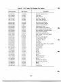
ILLUSTRA TIONS
Figure No.
1-1
1-2
1-3
1-4
1-5
2-1
2-2
2-3
2-4
2-5
2-6
2-7
2-8
2-9
2-10
2-11
2-12
2-13
3-1
3-2
4-1
A-I
A-2
A-3
A-4
A-5
A-6
B-1
B-2
B-3
C-l
C-2
C-3
Title
TMB II/TS03 System Configuration
TMB 11 Controller . . . . . . . . .
TS03 Tape Transport . . . . . . .
TS03-M Master Tape Transport with M8920 Adapter Module
TMB II/TS03 Functional Block Diagram
Space and Service Clearance, Top View
Cabinet Installation . . . . . . . . . .
TS03 Transport Physical Dimensions
Expander Box Backplane (BA 11 F box shown)
Power Cabling of TMBll System Unit in BAll F Box
TMBll Module Location and Cabling in BAlIK Box
TMBll Module Location and Cabling in BAIIF Box
Unibus Cabling . . . . . . . . .
TMB 11 Mounted in System Unit
M8920 Cabling
...... .
I/O Cable Connection Diagram
Securing TMB 11/TS03 Cables
Power Connection Diagram
Tape Threading Diagram
Controls and Indicators
Opening Head Shield
Reference Edge of Tape
Track-Bit Weight Relationship for 9-Channel Transport
Data Recording Scheme
Tape Recording Format
7-Channel Tape Format
9-Channel Tape Format
Front Panel Parts Identification
Tape Transport Parts Identification (Top View)
Tape Transport Parts Identification (Rear View)
Location of Read/Write and Erase Heads and Tape Cleaner
Proper Ceramic Washer Positioning
.... .
TS03 Tape Head Assembly . . . . . . . . . . . . . . . .
v
Page
1-1
1-3
1-4
1-5
1-8
2-2
2-4
2-5
2-6
2-7
2-9
. 2-10
2-11
2-11
2-12
2-13
2-14
2-15
3-1
3-2
4-3
A-I
A-2
A-3
A-4
A-5
A-6
B-2
B-4
B-5
C-3
C-3
C-4
TABLES
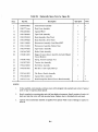
Table No.
1-1
1-2
2-1
4-1
A-I
A-2
A-3
B-1
B-2
B-3
B-4
B-5
B-6
B-7
B-8
Title
Controller Function . . . .
Applicable Documents
70-10570 Cable Connections
Customer Care Operations .
Five-Character Record . . .
CRC Character in Register When Writing
Track Assignments for Data and Parity
Illustrated Parts Breakdown for Figure E-l
Illustrated Parts Breakdown for Figure E-2
Illustrated Parts Breakdown for Figure E-3
Replaceable/Spare Parts for Figure E-l
Replaceable/Spare Parts for Figure E-2
Replaceable/Spare Parts for Figure E-3
DEC/Vendor TS03 Transport Part Numbers
TMB 11 Replaceable/Spare Parts . . . . . .
vi
Page
1-6
1-11
2-13
4-3
A-7
A-7
A-8
B-3
B-4
B-5
B-6
B-7
B-7
B-8
B-9
TMBll/TS03 DECmagtape System
7461·10
7447-2
TMBll/TS03 DECmagtape Systems
CHAPTER t
GENERAL INFORMATION
1.1
INTRODUCTION
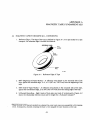
The TMBII-MA/MB* DECmagtape System (TMBII/TS03)t is a magnetic tape storage system that
interfaces with the PDP-II family of processors and peripherals and provides storage for digital information. The system reads and records digital data in parallel in a 9-channel, 800 bpi, industrycompatible NRZI format.
1.2
1.2.1
GENERAL DESCRIPTION
System Configuration
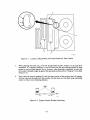
The TMBll/TS03 DECmagtape System is composed of the TMBll Controller and the TS03-M Master Tape Transport. The master tape transport is made up of a "slave" transport and an M8920
Adapter Module. A second "slave" transport (TS03-S) can be added that will interface with the adapter module contained in the master transport. Figure 1-1 is an illustration of the TMBII /TS03 system
configuration.
).
J.
..
WRITE
DATA
CONTROL
....
U
N
I
B
U
S
)
...
.)
(
...
READ
DATA
( INCLUDES
M8920
ADAPTER)
fAC
'I:
WRITE
DATA
COMMANDS
MASTER
DECMAGTAPE
TRANSPORT
TS03-MA/MB
STATUS
STROBE
.
A
DECMAGTAPE
CONTROLLER
TMB11
WRIT"E
READ
STROBE
A
(
'\
.,../
SLAVE
DEC MAGTAPE
TRANSPORT
TS03-SA/SB
(OPTIONAL)
READ DATA
~
STATUS
f Dc
fAC
7
11-3990
Figure 1-1
TMBII/TS03 System Configuration
*The TMBII-MA is a 1I5-Vac, 60-Hz system.
The TMBII-MB is a 230-Vac, 50-Hz system.
tThe TMBII-M system is commonly referred to by its component subunits, the TMBI1 and the TS03, hence the
manual title TMBll/TS03 DECmagtape System User's Manual. Within this manual the system is
referred to as the TMBll/TS03.
1-1
The TMBll Controller interfaces the DECmagtape system to the PDP-II Unibus. It controls data
transfers, issues control commands to the TS03 master, and monitors system operation. Each TMBII
can control two TS03 transports: a master and a slave.
The TS03-M transport consists of an M8920 Adapter Module and a transport. The M8920 processes
commands from the controller and issues motion and read/write commands to the master and slave
transports; the M8920 also monitors status lines from the master and slave transports. Any status
changes at the selected transport are reported immediately to the controller. In response to inputs from
the adapter, the tape transport controls tape motion and records and reads data on magnetic tape.
Two models of the master DECmagtape transport are available: the TS03-MA, which requires liS V,
60 Hz primary power, and the TS03-MB, which requires 230 V, 50 Hz primary power. Both models
also require +5 ± 5% V at 3 A and an AC LO signal.
The TS03-S transport consists of a tape transport only. In response to inputs from the master transport
adapter, it controls tape motion and records and reads data on magnetic tape. The TS03-SA requires
liS V, 60 Hz primary power and the TS03-SB requires 230 V, 50 Hz primary power.
1.2.2 Physical Description
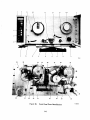
The TM B 11 (Figure 1-2) consists of the following six modules:
1.
2.
3.
4.
5.
6.
M 105 - Address Selector Module
M795 - Word Count and Bus Address Module
M796 - Unibus Master Control
M7821 - Interrupt Control Module
M7911 - Tape Drive Interface
M7912 - TMBII Unibus Registers
The six modules are plugged into a TMB II system unit that is mounted in an expander box. Unibus
input, Unibus output, and tape transport cabling also connect to the system unit.
The tape transport (Figure 1-3) is a single, rack-mounted drawer with the M8920 Adapter Board
mounted underneath on the master transports. The adapter is a hex height module; it is hinged at the
front corners and swings down as shown in Figure 1-4.
1-2
TMB11
MODULES (6)
7941-6
A.
Installed in BA 11 K Expander Box
TMB11
MODULES (6)
7997-2
B.
Installed in BA 11 F Expander Box
Figure 1-2 TMBll Controller
1-3
7941-8
Figure 1-3 TS03 Tape Transport
1-4
TS03
MASTER TAPE
TRANSPORT
7461-2
M8920
ADAPTER
MODULE
Figure 1-4 TS03-M Master Tape Transport with M8920 Adapter Module
1-5
1.3
SYSTEM FUNCTIONAL DESCRIPTION
NOTE
The TS03 tape transport operates at only one density
(800 bpi) and iin only one mode of operation (9
track). Consequently the system discussion that follows is restricted to these system limitations. The
TM B II is capable of other densities and can operate
in the 7 -track normal and 7 -track core dump modes.
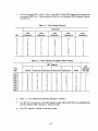
The basic functions performed by the controller are: off-line, read, write, write EOF, space forward,
space reverse, write-with-extended-IRG, and rewind. Each of these functions is briefly described in
Table 1-1.
Table 1-1
Controller Functions
Function
Off-Line
Description
The off-line function is used when it is desired to return control
to the tape transport so that tape can be rewound, reels
changed, etc. without using processor time.
The off-line function places the selected tape transport in the
off··line (local) mode and causes it to begin a rewind operation.
The controller cannot write on or read from the magnetic tape
when the off-line function is used.
Read
This function permits reading from the magnetic tape. During
the read operation, the data portion of the record is loaded into
the controller data buffer for transfer to the memory. The LRC
and CRC characters are read but not transferred into memory.
Write
This function permits writing on the magnetic tape. During the
write operation, data from the bus is loaded into the controller
data buffer register. The controller then transfers the data to the
tape transport write heads. The necessary LRC and CRC characters are generated by the master transport and written on the
tape following the data. The write function advances the tape
one record.
Write EOF
This function writes an end-of-file (EOF) mark on the tape.
When selected, this function erases a 3-in. segment of tape prior
to writing the first character. The EOF mark and the associated
LRC character are considered one record. The EOF mark is an
octal 23 character followed by an octal 23 LRC character.
1-6
Table 1-1
Controller Functions (Cont)
Function
Space Forward
Description
This function is used to skip over a number of records to find a
specific record on the tape. When selected, the space forward
function causes the tape transport to advance a specified n umber of records. The number of records is determined by the
value in the byte record counter. This value is loaded into the
byte record counter by the program.
Space forward is used for tape positioning only and, therefore,
does not affect information stored on the tape or in memory.
Space Reverse
This function is identical to the space forward function except
the tape moves in the reverse rather than in the forward
direction.
W rite-with- Extended-I RG
This function is identical to the write function except that a 3-in.
segment of tape is erased before writing the first character.
Rewind
This function is used for rewinding the tape on the feed reel so
that the tape can either be unloaded from the transport or operation can start at the beginning of the tape. When this function
is used, the tape moves in the reverse direction, at a much higher
speed (75 in./sec) than for other functions, until the beginningof-tape (BOT) marker is detected. When the BOT marker is
detected, the tape slows down and comes to a complete stop at a
point well beyond the BOT marker. It then moves forward
again until the BOT marker· is again detected, whereupon, it
comes to a final stop.
Rewind is used for tape positioning only and has no effect on
information stored on the tape or in the memory.
Figure 1-5 is a functional block diagram of the TMBII/TS03 DECmagtape System. The processor
initiates a TMBII/TS03 operation by addressing the TMBll registers via the address decoder and
loading the operation parameters· into the registers. The BUS CO-C 1 bits specify an out transfer (with
respect to the processor) causing SEL OUT to be asserted for the particular register addressed. As each
register is selected, the processor places the appropriate data on the Unibus data lines which is then
loaded into the register with the SEL OUT strobe. Thus, the command register receives the type of
operation to be performed; the byte-record count register receives the number of bytes to be transferred; and the current memory address register receives the memory address of the first byte to be
transferred.
·Parameters include four recording density choices that are sent to the transport as DEN 5 and DEN 8 bits. The
TS03 ignores these bits and operates at 800 bpi, 9-channel only.
1-7
REGISTER
SELECT
OUTPUT
MUX
COMMAND
DECODER
M7911
DATA BFR
OUT BIT 0-7
OPERATION PARAMETERS
BUS
INTERRUPT
BYTE/RECORD COUNT
16 STATUS BITS
DONE DELAYED
LOGIC
READ
CURRENT MEMORY ADDRESS
WRITE
M7821
WRITE
CARRY
----...:...,~
SEL lOUT
DONE LOGIC t - - - - - - l
FUNCTION COMMANDS (READ,WRITE, ETC.)
COMMAND
REGISTER
(REG 1)
~__________M~7~9~1~1j---t-i-i-1-----------------
WRITE
DATA READY
LOGIC
M7911
SEL 4 OUT
LRCS
DATA STB 2
(WRITE LOAD)
DATA BUFFER
(REG 4)
CARRY OUT 2
DATA BFR IN
BIT 0-7
NPR
LOGIC
BYTE/RECORD
COUNT
REGISTER
(REG 2)
RDS (READ LOAD)
M795
M796/M7821
M7912
STATUS
REGISTER
ERR (1)
M7911
ERROR
LOGIC
M7911
TMBI1/TS03
ADDRESS
DECODER
ELECT TMBII
REGISTERS) r-=..:;:....::....:.:..:..:...=-=---..
Ml05/M7912 ~=....::....:.:.:..:..=.:....-..
CMA
REGISTER
(REG 3)
CMA BIT 00
WRITE ByTE
SELECT
SEL LO BYTE
SEL HI BYTE
M7912
M795
S
READ BYTE
SELECT
M7912
HI DATA BYTE
I
1
LO DATA BYTE
I
I
I
I
I
I
I
1
I
I
~-----------------------------------------------------------TMBll------------------------------------------------------------------~:
_I
1
11-3988
Figure 1-5 TMBIl/TS03
Functional Block Diagram
(Sheet I of 2)
1-8
C
SEE
NOTE
EVEN PARITY
ZERO DETECT
a
WD3
(020)
13
W
-W 7,WP
SENSORI
ERASE
LOGIC
TOG
WRITE
LOGIC
REC
LRC PLS
READING -H
READ/WR ITE
DELAY COUNTER
TDG,7,13,14
....
7
l.J.J1
TIMING
... .....
TAPE
TENSION
SERVO
SYSTEM
SKEW
TDi2
ADJ
TD3
RD STRB
READ LOGIC
(PREAMP 4,5,6,7)
TDIO,11,12
7
o
SEE
NOTE
""'--T-I-M-E---'
~e~NTER
\
PULSE
STROBE PLS
GENERATOR
G
\
\
\
CONTROL
PANEL
""""""'0- TDB
FWD/REV MOTION
*
REWIND/OFF-LINE
DRIVE SELECT
J5
CONTROL
1
JI
r--
h
\
\
\
\
LP. RWD
\
CONTROL
I
I"
READ DATA LINES
(ROO - RD7, RDP)
CONTROL
INTERFACE
" / 1'1
FWD, REV, RWD
STATUS
/
"
........
TOB
MOTION
CONTROL
LOGIC
CAPSTAN
SERVO
SYSTEM
TD4,5
f------e
TD9
T07
TEST
BOX
//FWD.REV,FFW,FREJ
""""""'o-TDB
'"
STATUS
+5
OTL,TTL LOGIC
XPRT ROY
OP AMPS 4----1+,-10
RWNDG
EOT
WRL
DC MOTOR S
END OF TAPE
f - - - - 110/220/230
+----t:+,.:,-~24~_ _.2T~O~2J
* MB920 output jocks J2, J4 and J6 connect
LOAD POINT
:J>:pEL~
POWER
to J 2, J3 and J 1 respectively an the
second tape dri~e (if used)
WRLCK
_ _ _ _ Tc:n"l.C; ______
~
MFlQ?O----:1- 3989
NOTE: Lettering on connectors C and 0 are connecting points to other holf of this illustration
They do not represent connector pin l.tt.rinO·
Figure 1-5 TMB 11 !TS03
Functional Block Diagram
(Sheet 2 of 2)
1-9
The command register selects which transport is to be involved in the transfer via the SEL 0 - SEL 2
lines, supplies the function command to the command decoder which generates the required commands for the tape transport, and asserts the GO bit to the start logic. When the start logic senses that
the tape transport has been selected (SELR) and is ready (TUR), it asserts SET to the transport to start
the operation.
If a read operation is commanded, the transport command buffer asserts FWD MOTION to the
motion control logic which drives the capstan servo and moves the tape forward. When the tape is up
to speed, the transport read logic is enabled and starts to receive data from the read heads. The read
data out of the read logic (RDO-RD7, RDP) is checked for CRC, LRC, and vertical parity errors. If
any such errors are detected, the TMBII error logic is notified (CRCE, LRCE, VPE) for appropriate
corrective action.
The read data is supplied to the controller along with a read strobe (RDS) which signifies the availability of read data from the transport. RDO-RD7 becomes CHANO-CHAN7 and is gated to the data
buffer register where it is loaded into the register by RDS.
RDS also requests an NPR transfer from the NPR logic. When the request is granted BUS BBSY is
asserted by the logic along with DAT A---+BUS which gates the output of the data buffer to the Unibus
data bus (BUS DOO-015) v!a the register select output multiplexer. DATA---+BUS accomplishes this by
asserting either HI OAT A BYTE or LO OAT A BYTE from the read byte select logic according to
whether the CMA register is addressing the low byte or the high byte in memory. Thus, the data byte
from the data buffer will output on either BUS DOO-D07 or BUS D08-DI5. The next character read
will output on the alternate half of the data bus. When the NPR logic receives BUS SSYN from the
memory, it asserts NPR CLEAR BBSY which increments the byte/record counter and the CMA
register to prepare for the next transfer.
If a write operation is commanded by the command register, the GO BIT, in addition to enabling the
start operation logic, requests an NPR transfer from the NPR logic. When the request is granted, the
logic asserts BUS BBSY and BUS MSYN. The memory responds with SSYN to indicate that the first
data character is on the data bus (BUS OOO-DI5). The NPR logic asserts DATA STB 2 which loads
the data character into the data buffer, thus making it available to the transport as WDO-WD7. The
data character enters the data buffer via one of two gates. In the write mode CMA BIT 00 asserts either
SEL LO BYTE or SEL HI BYTE, according to whether the CMA register is addressing the low byte
or the high byte in memory, thereby enabling the gate corresponding to the location of the character
on the data bus.
Meanwhile, the start operation logic has asserted SET to the transport which, as in a read operation,
will cause the transport command buffer to assert FWD MOTION and start the capstan servo system
moving forward.
When the tape is up to speed, writing of the data characters begins. WD R (write data ready) from the
controller inhibits the transport shutdown counter and enables the write strobe generator via the
read/write delay counter. The write strobe generator produces REC pulses which record the data
characters on tape via the write heads. A parity bit is generated for each character and a CRC character is generated for each record. Each time a character is written on tape, a WRS pulse is issued to the
controller requesting the next character to be written. The WRS pulse makes an NPR request from the
NPR logic and the cycle is repeated. Note that in a write operation, the GO BIT makes the first NPR
request and the WRS strobes make the second and subsequent requests. After the NPR logic issues
DATA STB 2 it asserts NPR CLEAR BBSY which increments the byte/record counter and the CMA
register to prepare for the next transfer. When the byte/record counter senses that the desired number
of bytes has been transferred (read or written), it asserts CARRY OUT 2 which negates WDR to the
transport thereby inhibiting the write strobe generator and enabling the shutdown counter.
1-10
The end of a data transfer is indicated by the LRCS character at the end of each record. The LRCS
strobe is applied to the done logic which then asserts DONE DELAYED to the bus interrupt logic.
The interrupt logic requests a bus interrupt to notify the processor that the command operation has
been completed and the TM B II /TS03 is ready for another command.
The TMBII error logic monitors transport status including parity, CRC, and LRC errors and asserts
ERR(l) to the done logic if an error condition exists. Some types of errors warrant terminating an
operation before it is completed while others will wait until the end of the operation before asserting
ERR(l).
The processor can read the TMB II registers by addre,ssing the registers and requesting an in-transfer
(with respect to the processor) via the BUS CO-CI bits. The address decoder then asserts SEL IN for
the particular register selected which gates the register bits out to the data bus via the register select
output multiplexer.
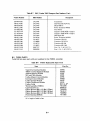
1.4 APPLICABLE DOCUMENTS
Table 1-2 lists PDP-II documents that are applicable to the TMBll/TS03 DECmagtape System.
Table 1-2
Applicable Documents
Description
Title
PDP-II Processor
and Systems
Manual
A series of maintenance and theory manuals that
provide a detailed description of the basic PDPII system.
PDP-II Processor
Handbook
A general handbook that discusses system architecture, addressing modes, the instruction set,
programming techniques, and software.
PDP-II Peripherals
Handbook
A handbook devoted to a discussion of the various peripherals used with PDP-II systems. It
also provides detailed theory, flow, and logic
descriptions of the Unibus and external device
logic; methods of interface construction; and
examples of typical interfaces.
DIGIT AL Logic
Handbook, 1973-74
Edition
Presents functions and specifications of the Mseries logic modules, accessories, and connectors
used in the TMB II Controller and the TS03
DECmagtape Transport. Includes other types of
logic produced by DEC but not used with PDPII devices.
Paper-Tape Software
Programming
Handbook
Provides a detailed discussion of the PDP-II
software system used to load, dump, edit,
assemble, and debug PD P-II programs;
input/output programming; and the floatingpoint and math package.
I-II
1.5 SPECIFICATIONS
Main Specifications
Storage medium
Capacity /tape reel
Data transfer speed
Drives/control, maximum
1/2 in. (1.27 cm) wide magnetic tape (industry compatible)
5 million characters
10,000 char/sec
2
Data 0 rganization
Number of tracks
Recording density
I nterrecord gap
Recording method
9
800 bpi
0.5 in. (1.27 cm) minimum
NRZI
Tape Motion
Read/write speed
Rewind speed
Tape drive
Reel braking
Speed variation
Start/stop distance
Start/stop time
12-1/2 in./sec
75 in./sec (rewind time = 2 min. maximum)
Single capstan
Dynamic servo control
3% instantaneous; 1% long term
0.19 in. (0.48 cm)
30 ms
Tape Characteristics
Length
Type
Thickness
Tension
Reel diameter
Reel hub
600 ft (182.9 m)
Mylar base, iron-oxide coated
1.5 mils (0.038 mm)
8.0 oz (227 g)
7 in. (17.8 cm)
3.69 in. (9.37 cm) diameter (industry standard)
Mechanical
Tape drive, mounting
Tape drive, size
Tape drive, weight
Control unit PDP-II
Mounts on slides in a standard 19 in. (48.3 cm) cabinet
10-1/2 in. (26.7 cm) panel height, 17 in. (43 cm) deep
37 Ib (16.7 kg)
Mounts in a single 16-1/2 X 2-1/4 in. system unit
(41.9 X 5.7 cm)
Power
Input current (TMBll)
Input current (M8920)
Input current (TS03)
Frequency
Input power
5 A at +5 Vdc
2 A at +5 Vdc
1 A at 90 to 132 Vac, or 0.5 A at 180 to 264 Vac
47 to 63 Hz, single phase
240 W at 115 Vac
120 W at 230 Vac
1-12
Operating Environment
Temperature
Relative humidity
Altitude
15° C to 32° C
20% to 80%, with maximum wet bulb 25 ° C and
minimum dew point 2° C
8000 ft (2438 m)
Miscellaneous
BOT, EaT detection
Broken tape detection
Magnetic head
Photoelectric sensing of reflective strip, industry
compatible
Ph otoelectric
Dual gap, read after write, 0.15 in. (0.4 cm) gap
Interchannel Displacement
Write
Read
Erase head
150 JLin. (3.8 JLm) maximum
150 JLin. (3.8 JLm) maximum
Full width
Models
TMBII-MA
TMBII-MB
TS03-MA
TS03-MB
TS03-SA
TS03-SB
Tape drive and PDP-II control, 115 Vac, 60 Hz
Tape drive and PDP-II control, 230 Vac, 50 Hz
Master tape drive, 115 Vac, 60 Hz
Master tape drive, 230 Vac, 50 Hz
Slave tape drive, 115 Vac, 60 Hz
Slave tape drive, 230 Vac, 50 Hz
1-13
CHAPTER 2
UNPACKING, INSTALLATION,
AND ACCEPTANCE TESTING
2.1
SITE PLANNING AND CONSIDERATIONS
2.1.1 Space Requirements
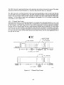
Figure 2-1 illustrates the space and service clearances required. Adequate space must be provided to
slide the equipment out of the rack for servicing and to open the front door on the TS03 DECmagtape
Transport. The TS03 and TMB 11 may be housed in separate cabinets. If this is the case, and the
cabinets are separated by long distances, consideration should be given to overhead trenching ducts for
the cabling.
2.1.2 Power Requirements
,
The TMBII/TS03 DECmagtape System can be operated from a nominal 115 or 230 Vac, 50/60 Hz
power source. Line voltage should be maintained to within 10 percent of the nominal value and the
frequency should not vary more than 3 Hz.
2.1.3 Environme.ntal Requirements
The operating environment should have cool, well-filtered, humidified air; a temperature range of 15°
to 27° C; and relative humidity of 40 to 60 percent.
2.2 UNPACKING
The TMB 11 /TS03 may be shipped in two different configurations: with the system installed in an
equipment rack or with each device packaged separately. Unpacking and installation procedures vary
greatly depending on the system configuration. For example, if the user has ordered a complete PDP11 system the TMBII/TS03 DECmagtape System is shipped installed in its appropriate rack with the
interconnecting cables installed. However, if only a part of the system is shipped because the user
already has a basic PDP-II system, then the TMBII/TS03 DECmagtape System is shipped separately
with the appropriate cables. Installation procedures may vary, depending on whether the unit is
mounted in a DEC- or customer-supplied cabinet, the number of transports in the system, and other
variable factors. Instructions are given for both cabinet and "separate device" configurations.
2.2.1 Cabinet Unpacking Instructions
To unpack the cabinet, proceed as follows:
1.
Remove outer shipping container.
NOTE
The container may be either heavy corrugated cardboard or plywood. In either case, remove all metal
straps first, then remove any fasteners and cleats
securing the container to the skid. If applicable,
remove wood framing and supports from around the
cabinet perimeter.
2-1
WINGING DOOR
(RH) NOTE 1
SWINGING DOOR
__
\
\LH
NO=~ ___________-,-__
I
-~ ,\.'" ~ ~"i':- """" --
-
'\
/'/
,//'"
-:/
//
//
"
""
~
'\'\
~
II
18 Y3~
(46.35cm)
\\
If
/1
7
y-
'\
~
~
\\
\
I
\
nj:!~~:~~~~~~~~~,f\n - - - - - - - - - - - - +
+
+
r--A--'
REMOVABLE
END PANEL-
CABLE ACCESS----__________
~__ ~
/--,~-Q--"
I
/
/
+
11
CASTER SWIVEL
RADIUS 2 13h~
(4) CASTERS
I
I
FAN
PORTS
30"
(76.2cm)
1-,
----.-,;;~.I
21 /16
(54.87 em)
I
NOTES:
1.' Door may be l.H. or R.H.
Allow space for either case.
48 7/32"
(122.47cm)
I
I
TS03 EXTENDED
FROM CABINET
II
19"
(48.26 cm)
L_________ J~
2. CABINET 717/1~(182.28cm) high
(floor line to cabinet top).
Figure 2-1
I
11-3092
Spac(~
and Service Clearance, Top View
2-2
2.
Remove the polyethylene cover from the cabinet.
3.
Unbolt cabinet(s) from the shipping skid. The bolts are located on the lower supporting side
rails and are exposed by opening the access door(s). Remove the bolts.
4.
Raise the leveling feet above the level of the roll-around casters.
5.
Use wood blocks and planks to form a ramp from the skid to the floor and carefully roll the
cabinet onto the floor.
6.
Roll the system to the proper location for installation.
2.2.2 Device Unpacking Instructions
Before unpacking the equipment, check the shipping list to ensure that the correct number of packages
has been received. Check the shipping list for the correct TMBll module types. Carefully remove each
device from its shipping carton. Note that the side mounts are already attached to the TS03 transport(s) and the mounting hardware is packed in a bag in each shipping carton.
2.3 INSPECTION
After removing the equipment from its container(s), inspect it and report any damage to the responsible shipper and the local DIG IT AL Sales Office. Inspect as follows:
1.
Inspect all switches, indicators, and panels for damage.
2.
Remove equipment covers where necessary and inspect for loose or broken modules, blower
or fan damage, and loose nuts, bolts, screws, etc.
3.
Inspect wiring side of logic panels for bent pins, broken wires, loose external components,
and foreign material.
4.
Check TS03 transport(s) for any foreign material that may have lodged in the tension arm,
reel hubs, and other moving parts.
5.
Check TS03 power supply for proper seating of fuses and power connectors.
6.
Inspect each TMBll module for shipping damage.
2.4 CABINET INSTALLATION - SYSTEM ALREADY INSTALLED
If the equipment is already mounted in the cabinet, proceed as follows:
1.
Lower the leveling feet so that the cabinet is resting on the floor, not on the roll-around
casters.
2.
Use a spirit level to level the cabinet; ensure that all leveling feet are firmly on the floor.
3.
Remove the shipping screws that secure the equipment to the cabinet.
4.
Plug the 861 power control ac power cord into a receptacle having the correct power, voltage
and frequency.
2-3
2.5 INSTALLATION OF SYSTEM COMPONENTS
The system components should be mounted in a 19 in. by 20 in. (48.3 cm by 50.8 cm) equipment bay.
Figure 2-2 shows a recommended cabinet layout. The equipment should be mounted from the top
down. Ensure that power is removed from the PDP-II and the TS03(s). If the TMBII and the TS03
are installed in more than one cabinet, ensure that the cabinets are tied to the same ground or install a
ground wire between the cabinets.
:t
TS{lI3
SLAVE
TS{lI3
MASTER
MOUNT GUIDES IN
19th HOLE FROM THE TOP
OF CABINET
MOUNT GUIDES IN
34th HOLE
NOTE 1
NOTE 2
PDP-II
NOTE 1
MOUNT IN
~ 69th HOLE
NOTE I
NOTES:
I. Expander box or other option.
2. Contains six cards of TMBII.
3. The TMBII may be installed in
a separate expander box.
r--
I
I
S61 - - '
POWER
CONTROL
lI
11-3996
Figure 2-2
Cabinet Installation
2.5.1 TS03 Mounting Instructions
To mount the TS03 (Figure 2-3) proceed as follows:
NOTE
If two TS03 transports (master and slave) are to be
installed, the slave (the unit without the M8920
Adapter Module) is installed at the uppermost
position.
1.
Remove the outer portions of the guides from the TS03 chassis by actuating the slide
releases and mounting the guides to the cabinet in the 19th hole from the top of the cabinet
using the eight screws provided. Ensure that the guides are level and parallel to each other.
2.
Lift the TS03 up and slide it carefully into the guides until the slide releases lock.
3.
Carefully lift the slide releases and push the transport fully into the cabinet.
4.
If a second TS03 transport is to be installed, repeat steps I through 3 above, but mount the
guides in the 34th hole.
2-4
17.00 ---~-------~
IU.llj
.
1.00
12.54}
.
.TE: DIIIEII51o.S FlIST 5_1 U[ 'I 'ItIlU.
DIIEISlo.S II .UEITHUES AlE II CEITlII£TnS.
CD
tv
------------------.. -
•
v.
!!DUIITlI& 1I0LES ARE F~
lERO NOIITILT TYPESLlD£
110. t3~C·I. (IIOT SUPPLIED
MITH UII:T) (DI"USIOIIS
TYPI CAL 011 10TH SIDES)
r--
--~
~.~~
~~
' \ _ __
..____--
IIOUlTlI'
SUIFACE
~~.
DUST tOYER 0'£11'
TO Al'PROIlIlATElf
110 DE&REES.
~.o=--'
~
--+
~
.~
•
0
-
-I
B
I
r-
1.25
(3.18)
I------------(~::~~!--------o*"-,
t---------------(!u:)--------'-.I
•
.
1.72
122.14)
I
l-
]7
(.93)
.25(.U)
""T
.45
(I.U)
DEtAIL "A"
TY" CAL SLOT
'AHUI
I.
·--------------(!U2)--------------'
'1-3046
Figure 2-3
TS03 Transport Physical Dimensions
2.5.2 TM B11 Installation/ Cabling
2.5.2.1
System U nit Installation
I.
Extend the expander box on its slides and remove the module access cover. (An extended
BA II K and BA 11 F box is shown in Figure 1-2.)
2.
Install a TMBII system unit in.to the expander box using the two captive screws (Figure 24).
o
AC
LO
TMBll BACKPLANE
POWER TERMINALS
0
+5 V GND
M8920
POWER
HARNESS
70-13008
OPTION POWER
HARNESS 70-09559
CAPTIVE
SCREWS
AC LO (YELLOW)
(2)
+5 V (RED)
GND (BLACK)
7997-3
TMB11 SYSTEM UNIT
Figure 2-4
Expander Box Backplane (BAIIF box shown)
2-6
3.
Install the option power harness by connecting the fast-on connectors to the system unit
backplane and the harness plug(s) to the expander box (Figure 2-5).
4.
I nstall the M8920 power harness by connecting the three fast-on connectors as shown in
Figure 2-4. The harness color code is:
+5V
ACLO
GND
5.
red
yellow
black
Dress the M8920 power harness along the top of the BAIIF expander box as shown in
Figure 2-5. If a BA II K box is used dress the harness underneath the expander box.
M8920
POWER HARNESS
70-13008
OPTION POWER
OPTION
POWER HARNESS
70-09559
Figure 2-5
Power Cabling of TMBll System Unit in BAllF Box
2-7
2.5.2.2
Module Installation
1.
Check the jumpers on the M7821 module for a bus interrupt address of 224.
2.
Check the priority jumper on the M7912 module for the correct interrupt priority level
(usually BR5).
3.
Check the jumpers on the MI05 module for the correct address range for the TMBII registers (772520 to 772536).
4.
Plug the six TMB II modules and a M930 terminator module into the system unit according
to Figures 2-6, 2-7, and engineering drawing BD-TMBII-0-7.
2.5.2.3 Unibus Cabling - System units are connected to the Unibus in daisy-chain fashion as shown in
Figure 2-8. Each unit has a Unibus in- and a Unibus out-jack. A BCIIA cable connects the Unibus
into the first system unit. M920 jumper modules connect the Unibus to the other system units in a
given configuration. An M930 terminator module is installed in the Unibus out-jack of the last system
unit in the chain. If the Unibus is to be carried onto another expander box, a BCIIA Unibus cable is
used to connect the Unibus from the Unibus out-connector of the last system unit in the first box to the
Unibus in-connector of the first system unit in the second box. The Unibus is terminated by an M930
module installed in the out-jack of the last system unit.
Install the Unibus in-cable, Unibus out-cable, M920 jumper and/or M930 terminator according to the
particular configuration. The Unibus in-connections on the TMBII system 'unit are slots Al and B1.
The Unibus out-connections are slots A4 and B4 (Figure 2-9 and engineering drawing BD-TMBII-O7). The configuration shown in Figure 2-6 utilizes a Unibu~ out-cable and an M920 bringing the
Unibus in from the next system device. The configuration shown in Figure 2-7 uses M920 jumpers for
both input and output Unibus connections.
NOTE
BCIIA cable connectors will plug into the system
units either way but will not fully seat if incorrectly
installed. Make sure the connectors are fully seated
and that the notches on the connector edges are up
against the system unit slots.
2.5.2.4 Slave Bus Cabling - Connect the BCIIA slave bus cable to slots E4 and F4 on the system unit
(Figure 2-9). Install an M930 terminator module into slots E3 and F3 to terminate the slave bus
(Figure 2-6 and engineering drawing BD-TMBII-0-7).
2.5.2.5 Securing Cables - If the installation is performed in a BA II F expander box, lift the cable
trough cover and feed the BC IIA cable(s) through the trough and the cable holding bracket.
If the installation is performed in a BA II K expander box, perform the following:
1.
Remove one screw from the center strain relief and loosen the other (Figure 2-6).
2.
Swing the strain relief out and place the BCIIA cable(s) up against the edge of the chassis.
3.
Swing the top of the strain relief back into place.
4.
Insert the removed screw and tighten both screws.
2-8
CABLE STRAIN
RELIEF
BC11A UNIBUS
OUT CABLE
M7821
M920
M796
M795
M105 .
BC11A CABLE TO ~
TAPE TRANSPORT
M930
M7912
M7911
7941-5
Figure 2-6
TMBII Module Location and Cabling in BAlIK Box
2-9
M920
M7821
M796
M795
M105
BC11A CABLE TO
TAPE TRANSPORT
M930 (NOT SHOWN)
7997-1
Figure 2-7
TMBII Module Location and Cabling in BAllF Box
2-10
/
BC11A
UNIBUS
CABLE
.
M930
UNIBUS
TERMINATOR
MODULE
/
BCII A
UNIBUS
CABLE
11-4121
Figure 2-8
Unibus Cabling
A4
UNIBUS
OUT {
A1 }
B4
- + - - - B1
(NOT SHOWN)
TAPE
TRANSPORT
I/O
UNIBUS
IN
t(:~T
SHOWN)
,
F4 - - - - -
7941-1
Figure 2-9 TMBll Mounted in System Unit
2-11
2.5.3 TS03 Cabling
I. Slide out the TS03-M drawer.
2. Remove the M9820 front cover (Figure 2-10).
70·10570
CABLES TO
TAPE
TR
M8920
BC11A CABLE
TO TMB11
A
7941-7
Figure 2-10
M8920 Cabling
3. Unscrew the two knurled screws holding the M8920 module and allow the module to hang
down as shown in Figure 2-10.
4. Connect the BCIIA cable from the TMBII system unit to the "C" and "0" connectors on
the M8920 module using two H870 edge connectors.
5. Install the 70-10570 master/slave cables between the M8920 module connectors (Jl through
J6) and the TS03 master and slave transport connectors as listed in Table 2-1 and shown in
Figures 2-10 and 2-11.
2-12
TS03 MASTER (TS03-M)
TS03 SLAVE (TS03-S)
TRANSPORT (REAR VIEW)
TRANSPORT (REAR VIEW)
H870
EDGE CONNECTORS
BCllA
SLAVE BUS CABLE
M930 TERMINATOR
11 -3999
Figure 2-11
Table 2-1
6.
110 Cable Connection Diagram
70-10570 Cable Connections
From
M 8920 Adapter Board
Connector
To
TS03 Master
Connector
JI
J3
J5
J2
J4
J6
J2
J3
JI
TS03 Slave
Connector
J2
J3
JI
Remove one screw from each of the three cable strain reliefs and loosen the other (Figure 212).
7. Swing the strain reliefs out and place the BellA cables up against the edge-of the chassis.
Leave enough slack so that the cables are not strained when the M8920 module is swung
down.
8. Swing the top of the strain reliefs back into place.
9.
Insert the removed screws and tighten all screws.
2-13
STRAIN RELIEFS (3)
7941-3
Figure 2-12
10.
Securing TM B 11 /TS03 Cables
Feed the M8920 power harness over the hinged edge of the M8920 module.
11. Connect the harness to the fast-on connectors on the M8920. The color code for the connections is:
+5V
ACLO
GND
red
yellow
black
12. Neatly dress all cables. Leave service loops so TS03 transports can be extended from the
cabinet and the M8920 adapter can be swung down on its hinges.
13. Swing the M8920 module up into position and secure it with the two knurled screws.
14.
Replce the M8920 front cover. Slide in the TS03 drawer.
15. Plug the TS03 master and slave transport ac power cords into the 861 power control switched receptacle as shown in Figure 2-13.
2-14
T S03 MASTE R (TS03 - M )
TS03 SLAVE (TS03-S)
TRANSPORT (REAR VIEW)
TRANSPORT (REAR VIEW)
M8920 ADAPTER
SWITCHED AC PO WE
POWER HARNESS
(70-13008)
TM811
SYSTEM UNIT
861 POWER CONTROL
PRIMARY
AC POWER
11-3998
Figure 2-13
Power Connection Diagram
2.6 ACCEPTANCE TESTING
Perform the operating instructions contained in Chapter 3. Refer to Paragraph 5.6 of the
TMBll /TS03 Maintenance Manual (corrective maintenance) if any failures occur. Run the diagnostics
as described in Paragraph 5.6.1. If the TMBll/TS03 system operates normally and the diagnostics
show satisfactory results, then the system has been properly installed and system operation is up to
specification.
2-15
CHAPTER 3
SYSTEM OPERATING INSTRUCTIONS
3.1 CONTROL AND INDICATORS
Figure 3-2 describes the controls and indicators.
3.2
OPERATING PROCEDURES
3.2.1 Tape Threading
To thread the tape on the transport, proceed as follows:
1.
Raise the latch of the quick-release hub and place the tape file reel to be used on the supply
hub (Figure 3-1) with the write enable ring side next to the transport deck.
2.
Hold the reel flush against the hub flange and secure it by pressing the hub latch down.
3.
Thread the tape along the path as shown in the threading diagram (Figure 3-1).
4.
Holding the end of the tape with a finger, wrap a few turns counterclockwise around the
takeup hub.
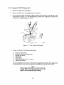
Figure 3-1
Tape Threading Diagram
3.2.2 Power Up
Press the POWER ON/OFF switch to ON to apply ac power to the transport.
3-1
UNIT SELECT Plug - One of two plugs can be inserted. designating unit as 0 or 1.
NOTE
In 8 single drive sytem, the drive is always
designated 8S drive O. In a dual drive system,
either drive can be designated as drive O.
WRITE ENABLE Indicator - Illuminated whenever a reel
with a write enable ring is mounted on the supply hub.
D
o
WAIT •
• NA.L.
0
ON LIN.
0
LOAO
0
A.WINO
ON
ON LIN E Pushbutton/Indicator - A momentary pushbutton.
which functions as alternate action. When first activated. the
tape unit is placed in an on-line condition; when the tape
unit is on-line. it can be remotely selected and will be ready
if tape is loaded to or past the load point. When activated
again it takes the unit off-line. The indicator is illuminated in
the on-line condition. The load function must be performed
before the unit will go on-line.
D
D
D
LOAD Pushbutton/Indicator - The momentary pushbutton
activates the reel servos (tensions tape) and starts the load
sequence. The indicator is illuminated when the reel servos
are activated and tape is tensioned.
B
"·3041$
REWIND Pushbutton/Indicator - The momentary pushbutton activates a rewind operation. This control is enabled only
when tape is tensioned and the unit is off-line. The indicator
is illuminated during either a local or a remote rewind
operation.
POWER Switch - The ON/OFF switch applies ac power to
the tape transport.
Figure 3-2 Controls and Indicators
3.2.3 Tape Loading
Pressing the LOAD pushbutton energizes the reel servos and initiates a load sequence. Tape advances
to the load point marker and stops. If for some reason the load point marker is already past the sensor
(as, for example, in restoring power after at shutdown), tape will continue to move. Under these conditions, press LOAD and then REWIND and the tape will rewind to the load point. Once pressed, the
LOAD switch is illuminated and is inactive until power has been turned off or tape is removed from
the machine.
3.2.4 Placing Tape Unit On-Line
After the tape is properly threaded and has been loaded and brought to the load point, press the ON
LINE pushbutton and check that the ON LINE indicator illuminates. (The REWIND pushbutton is
disabled when the tape unit is on-line.) On-line status enables the tape unit to be remotely selected and
to perform all normal operations under remote control.
3-2
3.2.5 Tape Rewind and Unloading
Provision is made in the TS03 transport for rewinding a tape to the load point under remote control.
However, this operation may also be performed manually as follows:
1.
If the 0 N LINE indicator is illuminated, press the ON LINE pushbutton. Check that the
indicator extinguishes when pressure is removed.
2.
Press the REWIND pushbutton. The tape will now rewind to the load point marker.
3.
After the tape has been positioned at the load point under remote or local control, it can be
unloaded by pressing the REWIND pushbutton to rewind the tape past the load point to the
physical beginning of the tape.
NOTE
The rewind sequence cannot be stopped until the tape
has rewound either to the load point or until tension
is lost at the physical beginning of the tape.
3.2.6 Power Shutdown
Press the POWER ON /OFF switch to OFF to remove ac power from the transport. A tape transport
should not be turned off when tape is loaded and is past the load point marker. The TS03 transport is
designed to prevent physical damage to the tape in the event of power failure, and to minimize operator error that could destroy recorded data. In the event of power failure during tape unit operation,
manually wind the tape forward several feet before restoring power. When power has been restored,
press the LOAD pushbutton, then the REWIND pushbutton. This will rewind the tape to the load
point. If desired, the tape can then be advanced to the data block nearest the point at which the power
failure occurred by initiating the appropriate control commands.
CAUTION
In dual drive systems, when one drive is on-line and
running, do not turn power off at the unused drive,
i.e., do not set the TS03 POWER ON-OFF switch
to OFF. To do so may result in data errors on the
drive that is running.
3-3
CHAPTER 4
CUSTOMER CARE AND
PREVENTIVE MAINTEN AN CE
4.1 CUSTOMER RESPONSIBILITIES
The customer is directly responsible for:
1.
Obtaining operating supplies, including disk cartridges, disk packs and filters, magnetic
tape, DECtape, paper tape, cassettes, printer paper, printer ribbons, plotter paper, etc.
2.
Supplying accessories, including disk storage racks, DECtape storage racks, carrying cases
for disk cartridges and DECtape, cabinetry, tables, and chairs.
NOTE
Users of Digital Equipment Corporation equipment
may obtain the proper operating supplies and accessories by contacting:
Digital Equipment Corporation
DEC Supplies Order Processing
146 Main Street
Maynard, Massachusetts 01754
Phone: (617) 897-5111, Ext. 5218, 5907
Boston Area: (617) 890-0330
TWX: 710-347-0212
Cable: Digital Mayn
Telex: 94-8457
3.
Maintaining the required logs and report files consistently and accurately.
4.
Making the necessary documentation available in a location convenient to the system.
5.
Keeping the exterior of the system and the surrounding area clean.
6.
Turning off the teletypewriter and/or line printer when these devices are not in use.
7.
Ensuring that ac plugs are securely plugged in each time equipment is used.
8.
Performing the specific equipment care operations described in Paragraphs 4.2 and 4.3 at
the suggested frequencies or more often if usage and environment warrant.
4.2
4.3
CARE OF MAGNETIC TAPE
1.
Do not expose magnetic tape to excessive heat or dust. Most tape read errors are caused by
dust or dirt on the read head; it: is imperative that the tape be kept clean.
2.
Always store tape reels inside containers when not in use; keep the empty containers tightly
closed to keep out dust and dirt:.
3.
Never touch the portion of tape between the BOT and EOT markers; oil from fingers
attracts dust and dirt.
4.
Never use a contaminated reel of tape; this will spread dirt to clean tape reels and could have
an adverse affect on tape transport reliability.
5.
Always handle tape reels by the hub hole; squeezing the reel flanges could lead to tape edge
damage in winding or unwinding tapes.
6.
Do not smoke near the tape transport or storage area; tobacco smoke and ash are especially
damaging to tapes.
7.
Do not place magnetic tape near any line printer or other device that produces paper dust.
8.
Do not place magnetic tape on top of the tape transport, or in any other location where it
might be affected by hot air.
CUSTOMER PREVENTIVE MAINTENANCE OF TS03 TAPE TRANSPORT
4.3.1 General
Digital Equipment Corporation tape transports are highly reliable precision instruments that will
provide years of trouble-free performance when properly maintained. A planned program of routine
inspection and maintenance is essential for optimum performance and reliability. The following inform ation will assist the customer in caring for his equipment and ensure the highest level of performance
and reliability.
4.3.2 Preventive Maintenance
To ensure trouble-free operation, a preventive maintenance schedule should be kept. Preventive
maintenance consists of cleaning only a few items, but the cleanliness of these items is very important
to proper tape transport operation. The frequency of performance will vary somewhat with the environment and degree of use of the transport. Therefore, a rigid schedule applying to all machines is
difficult to define. The recommended periods apply to units in constant operation in ordinary environments. They should be modified if experience shows other periods are more suitable. Table 4-1 contains the cleaning instructions.
Before performing any cleaning operation, remove the supply reel and store it properly. All items in
the tape path must be cleaned on a per-shift basis. In cleaning, it is important to be thorough yet gentle
and to avoid certain dangerous practices. It should be remembered that the tape cleaner is a strong
cleaning agent and should not come in contact with painted surfaces or plastic.
Refer to Appendix C for additional magnetic tape drive cleaning instructions.
CAUTION
Do not use acetone or lacquer thinner, aerosol spray
cans, rubbing alcohol, or excessive cleaner. Be
extremely careful not to allow the cleaner to penetrate ball bearings, tension rollers, and motors.
4-2
4.3.3
Materials Required
1.
2.
DECmagtape system and magtape cleaning kit
Lint-free wipers.
Table 4-1
Customer Care Operations
Frequency
Once
per Shift
Operation
Using cotton-tipped wooden swabs moistened with head cleaner inspect and clean
the following (Figure 4-1); then remove any residue with a clean, dry swab.
Head and head shield
Load pointjend-of-tape sensor
Missing tape sensor
Both tape guides
Weekly
Monthly
Tape cleaner
Tape tension roller (not shown)
Capstan (not shown)
1.
Using a lint-free cloth or wipe, dust the inside and outside of the plexiglass door. If dirt and dust have accumulated, a mild soap and water
solution or antistatic cleaner may be used. Ensure that the door is dry
before returning the tape transport to service.
2.
Using a lint-free cloth or wipe moistened with alcohol (at least 91 %),
remove all built-up material on the reel hub surfaces, especially around
the O-ring. Remove any residue with a clean, dry wipe.
Dust and vacuum the exterior of the outer door and top of the cabinet.
HEAD COVEA REMOVED FDA CLARITY
11-3061
Figure 4-1
Opening Head Shield
4-3
APPENDIX A
MAGNETIC TAPE FUNDAMENTALS
A.I
MAGNETIC TAPE FUNDAMENTALS - DEFINITIONS
1. Reference Edge - The edge of the tape as defined by Figure
transport, the reference edge is toward the observer ..
A~1.
For tape loaded on a tape
TAPE
LEADER
~---SUPPLY
REEL
10-1265
Figure A-I
Reference Edge of Tape
2. 'BOT (Beginning-of-Tape) Marker - A reflective strip placed on the nonoxide side of the
tape, against the reference edge, 15 ft, ± 1 ft (457 cm, ±30.5 cm) from the beginning of the
tape.
3. EaT (End-of-Tape) Marker - A reflective strip placed on the nonoxide side of the tape,
against the nonreference edge, 25 to 30 ft (762 to 914 cm) from the trailing edge of the tape. '
4. 9-Channel Recording - Eight tracks of data plus one track of vertical parity. Figure A-2
shows the relationship between track and bit weight for a 9-channel transport.·
*When the track vs bit channel standard was adopted, the outer tracks were more susceptible to bit dropping
errors. Consequently, channels containing the least Is were assigned the outer locations on the tape.
BIT WT TRACK
22_120
-
2 -
RD 7
>----
24 - 3 -
RD 6
RD 5
P -4-
RD 4
25_5-
RD 3
26_6-
RD 2
27_7-
RD 1
2'-8-
RD IZ!
23 - 9 -
RD P
READ AMPS
READ HEAD
11-3091
Figure A-2
Track-Bit Weight Relationship for 9-Channel Transport
5.
Tape Character - A bit recorded in each of the nine channels.
6.
Record - A series of consecutive tape characters.
7.
File - An undefined number of records (minimum = zero, no maximum).
8.
Interrecord Oap (IRO) - A length of erased tape used to separate records [0.5 in. (1.27 cm)
minimum for 9-track; maximum IRO is 25 ft (762 cm)].
9.
Extended IRO - A length of erased tape [3 in. (7.62 cm) minimum] optionally used to
separate records. It must be used between BOT and the first record.
10. Tape Speed - The speed at which tape moves past the read/write heads; normally stated in
inches per second.
II.
Tape Density - The density of sequential characters on the tape, It is normally specified in
bytes per inch (bpi), which is equivalent to characters per inch ..
12. Write Enable Ring - A rubber ring that must be inserted on the supply reel to allow the
transport to write on the particular tape. This safety feature helps prevent accidental
destruction of previously recorded data.
13. Tape Mark (TM) - A record written on the tape to designate the end of a file; sometimes
referred to as a file mark (FMK).
A.2 RECORDING METHODS AND DECmagtape FORMATS
The D ECmagtape system is an on-line mass storage system for programs or data. Data is recorded on
tape in vertical rows called characters. Each character consists of eight data bits and one vertical parity
bit. The vertical parity bit is program-selected as even or odd. The odd parity bit guarantees that each
character records at least one 1 bit.
The parity bit is generated according to the rule that the number of Is in a character (parity bit
included) is odd or even. For example, if odd parity is used and the character contains an even number
of 1 bits, the parity bit is generated as a 1 bit and an odd number of 1 bits are recorded; then, if an even
number of bits are read back from tape, a vertical parity error is generated to notify the program that
the data is in error.
A-2
The data characters are recorded in blocks of characters termed records (Figure A-3). Each record
contains a specified n umber of characters determined by the word count. The minimum record length
is 3 characters; the minimum word count is the 2's complement of 3 or 7775 8 •
1-------..
FILE ------+01_1
FILE MARK =23 8
FILE MARK = 23 8
r-0.6~
Iot---APPROX 3.8"--001
I
,
DATA PREVIOUS~
RECORD
j.-1RG--I-- DATA NEXT
I
RECORD
0 • 6'!-e.I
I--
,
III~*+*,
l
r
CRhc
lRCC
LAST DATA
CHARACTER
OF PREVIOUS
FILE
~**-1
FILE tMARK
r
LRCC
1111 ~*+*'
J
'II
LAST DATA
CHARACTER
OF PREVIOUS
RECORD
FIRST DATA
CHARACTER
OF NEXT
FILE
J
IIIIII
CR~C LRCC
i
IRG
FILE MARK AND GAP FORMAT
I
LFIRST DATA
CHARACTER
OF NEXT
RECORD
FORMAT
*. 3 CHAR. SPACE
* * . 7 CHAR.SPACE
11-3069
Figure A-3
Data Recording Scheme
Records are separated by interrecord gaps (IRGs). The IRG is 0.5 in. (1.27 cm) minimum [approximately 0.6 in. (1.5 cm) in normal operation], but may be extended to 3 in. (7.62 cm) by performing an
extended gap operation. Tape IRGs (unrecorded areas) provide areas on the tape for the transport to
start or stop and also separate data records.
A.2.A
NRZI Recording Method (non-return-to-zero change on one)
I n the N RZI recording method, a 1 bit is represented by a reversal in the direction of tape magnetization on a track; a 0 bit is represented by no change in tape magnetization.
A-3
A.2.2 9-Channel Tape Format
The format (Figure A-4) is composed of from 18* to 2048 nine-bit characters spaced 1/800 in. (3 mm)
apart, followed by 3 character spaces, a eRC character, 3 more spaces and an LRC character. This
unit of data is called a record. At 800 characters per inch, the record is between 1/32 in. (79 mm)
minimum and 5 in. (12.7 cm) maximum. Between each record is a gap of at least 1/2 in.t The tape
structure consists of a number of records followed by a file mark (Figure A-3). Since data is recorded
and read at high speed, IROs are used to provide space for starting and stopping a t~pe transport. A
transport accelerates from standstill to full speed in approximately 0.2 in. (0.5 cm) of tape and decelerates from full speed to standstill in 0.2 in. (0.5 cm) of tape; thus, the minimum IRO of 0.5 in. (1.27 cm)
provides adequate space for starting and stopping the tape transport.
r
!
LRC
O.oos":!: 10% (NOTE 3)
eRe 0.005'"
10%
i
GAP-~IL--c=---~oeK
INTERBLOCK
0.50 MIN
(NOTE
2)
REFERENCE EDGE
(FRONT FLANGE
OF REEL>
WRITE TRACK
0.043" MIN
2048 MAX USASCII CH
18 MIN USASCII
II I I I
CH
LOAD POINT
BEGINING OF
TAPE REFLECTIVE
~~"!:.. ~~R~~ _ ~ STRIP ON
NONOXIDE(SHINY)
SIDE OF TAPE
~E---I---'- PAR I TY (000)
1111111111
r - - - - - - -- - -
:-.-
I1111111I
END
OF
TAPE
J++H+r------------~-r-+~+H~.+
BEGINING
OF
TAPE
11111111111111111111
END POINT
END OF TAPE
REFLECTIVE
STRIP ON NONOXIDE
(SHINY) SIDE OF
TAPE
>
1 - - - -_
TAPE _
MOTION_- - - - ,
8E- 0500
LEGEND:
NOTES:
BPI
BOT
LRC
CRC
1. Tape is shown with oxide side up, read/write head on same side as
oxide. Tape is shown representing 1 bits in all NRZI recording; 1
bit produced by reversal of flux polarity, tape fully saturated in
each direction.
Tape Bits per Inch
Beginning of Tape
Longitudinal Redundancy Check
Cyclic Redundancy Check
2. Tape to be fully saturated in the erased direction in the interrecord
gap and the initial gap.
3. An LRC bit is written in any track if the longitudinal count in that
track is odd. Character parity is ignored in the LRC character.
4. CRC - Parity of CRC character is odd if an even number of data
characters are written, and even if an odd number of characters
are written.
Figure A-4
Tape Recording Format
·USASCII program standards, not a hardware limit.
in. (1.27 cm) minimum; 0.6 in. (1.5 cm) nominal.
to.~
A-4
The CRC character is generated during a write operation and written at the end of a record. The check
character performs the same function to a record as the parity bit does to a character.
The LRC character is the final character in the record and is generated so that for each track the sum
of 1 bits (CRC character included) is even. The LRC character is written on tape by clearing the write
buffer in the tape transport after the CRC character is written. The LRC strobe resets the write buffer,
causing a 1 to be written on each track containing an odd number of Is; a 0 is written on each track
containing an even number of Is.
A.2.3 7-Channel Tape Format
Each character frame in a 7-channel tape (Figure A-5) consists of six character bits (B, A, 8,4, 2, 1) in
descending order of significance. The parity bit, or check bit (C), is the seventh bit and is set or cleared
by the transport write head. One byte of a data word corresponds to one tape character. However,
because one byte contains eight bits and a tape character contains only six data bits, two bits within
each byte are not used. During a read operation, the extra bits are forced to 0; during a write operation, the bits remain unchanged. During the core dump mode of operation, one byte corresponds to
two tape characters. Thus, all bits within the byte are used; however, the two most significant bits on
the tape are not used.
FORWARD
TAPE
MOTION
•
r
ONE BYTE DURING
CORE DUMP MODE
TAPE CHANNELS
(PARITY) C
B
A
8
4
2
~-----~
LI!~T_!~I!J
I
1
r- +
BOT GAP
I
I
I
I
I
1
DATA
3-CHARACTER
MIN.
-+
I
I
1
'--_ _
1_'_ __
3
fNTERRECOR1CHARACTER
GAP
PERIODS
(IRG)
N~xicgR~A
o.7-CHANNEL DATA FOR MAT
CHARACTER
.1..
1
+ -+
LARSETCODRADTA _ -.....
EOF
---~~ EXTEND.ED IRG - - - ........IN BLOCK
RECORD
3 BLANK
CHARACTER
b. EOF RECORD
PERIODS
IRG
BEGINNING
OF NEW
DATA BLOCK
11-0391
Figure A-5
7-Channel Tape Format
A-5
The magnetic tape is divided into data records, each record separated by an interrecord gap (lRG). A
record for 7-channel tape may be any length from a minimum of 24 characters to a maximum of 4008
characters. In a block format, a number of records are written together with an IRG before the first
record and after the last record. In either case, the IRG is an unused portion of tape preceding and
following the record or the block.
The longitudinal redundancy check (LRC) character is written after the data and is separated from the
data by three character spaces. Each bit in the LRC is such that the total number of bits in any specific
channel is even.
The end of a block of records is indicated by an end-of-file mark character. The end-of-file (EOF)
mark is separated from the data by an extended IRG. The extended IRG is a 3-in. strip of blank tape
compared to the standard 3/4-in. IRG for 7-channel tape and the I/2-in. IRG for 9-channel tape. The
EOF mark and associated LRC character are considered to be one complete record.
The 9-channel tape format (Figure A-6) is similar to the 7-channel format; however, because each
character consists of eight data bits and one parity bit, a byte corresponds to a tape character. Therefore, there is no need for a core dump mode, because information can be transferred from the system
to the tape on a one-to-one ratio. A record for 9-channel tape may be any length from 18 characters to
2048 characters. In addition, the 9-channel format includes a cyclic redundancy check (CRC) character. Data is followed by three blank character periods, the CRC character, three more blank character
periods, and the LRC character. The LRC character is followed by an IRG as before.
r----~-~=~ ONE
'0
1I
l
i1
t 11 1,
ttl tit
ttl ttl
I
1 1 I 1 1
1 Til 1 I
t
I
1
1
3
2
II
1I
1
1
89
7
6
5
(PARITY)4
r------...,
L~2! _T!-~ J
rL
BYTE
mrI 1
1
BOT G A P - + - 3
t1
1
11
11
1I
1
1
1
lit
1
1
1
1
'C~~:CTER-+CHAR~CTER+CHAR~TER+-INTE~~~CORD+ ~~~l
MIN.
PERIODS
PERIODS
(IRG)
RECORD
" -0392
Figure A -6
A.3
9-Channel Tape Format
CYCLIC REDUNDANCY CHECK (CRC) CHARACTERS
The CRC character provides a method of error detection and correction on magtape transports. The
code has nine check bits that form a check character at the end of each record. To perform a correction, a record in which an error has been detected must be reread into memory with the LRC and CRC
characters fbr prog'ram evaluation. Errors involving more than one track can be detected but not
corrected.
The CRC character is generated as follows:
I.
The CRC register is cleared at the beginning of each record. As each data bit is written on
tape, it is exclusively ORed with its corresp<!>nding bit in the CRC register.
2.
The CRC register is shifted one position to the right after the exclusive OR operation has
taken place.
A-6
3.
The bits entering CRC 2, CRC 3, CRC 4, and CRC 5 of the CRC register are inverted if the
bit entering CRCP is a I. Data is shown in Table A-I; the resultant CRC character is shown
in Table A-2.
Table A-I
Five-Character Record
Characters
Bit
P
0
I
2
3
4
5
6
7
Data
Character 0
Data
Character 2
0
0
0
1
0
0
I
0
0
I
0
Table A-2
Data
Character 3
Data
Character 4
Data
Character 5
1
0
1
1
0
0
0
0
1
1
0
1
1
1
1
1
0
1
1
1
1
I
0
0
I
0
I
1
I
0
0
0
0
1
CRC Character in Register When Writing
CR C Register
CRC
Bits
Cleared
CRCP
CRCO
CRCI
CRC2
CRC3
CRC4
CRC5
CRC6
CRC7
0
0
0
0
0
0
0
0
0
Character I Character 2 Character 3 Character 4
0
0
I
0
0
0
0
0
0
1
0
0
0
0
I
0
1
0
0
0
0
1
1
1
1
0
0
Final
1
0
0
0
0
0
1
0
0
1
1
1
0
0
0
1
0
1
CRC
Character
On Tape
0
1
1
1
1
1
1
1
1
4.
Steps 1 - 3 are repeated for each data character of record.
5.
At CRC time, all positions of the CRC register, except CRC2 and CRC4, are complemented
and the resultant eRC character is written on tape.
6.
The CRC register is cleared for the next record.
A-7
A.4 LONGITUDINAL REDUNDANCY CHECK (LRC) CHA~RACTER
The LRC character is written three spaces after the CRC character. The vertical parity bit is always
written on the LRC character; the vertical parity of LRC is never checked. The L~C character makes
the longitudinal parity even for the entire record, including the CRC. The LRC is generated by the
LRC register in the following manner:
1.
The LRC register is cleared at the beginning of a record.
2.
As characters are written on tape, corresponding 1 bits complement the LRC register at the
time data is written on tape.
3.
At LRC time, the LRC strobe clears the write buffer and 1s are 'written on tape in only those
channels for which the write buffer is set prior to clearing.
4.
Following this method, the LRC character forces an even number of bits to be recorded on
each track of the tape. The CRC character is included in determining the LRC character.
A.5 DATA FILES
As previously stated, a record is a group of characters preceded by an IRG and terminated by three
spaces, a CRC character, three more spaces, and an LRC character. A file is a group of records
separated by IRGs and terminated by a 3 in. (7.62 cm) gap followed by a file mark. The file mark is a
record consisting of a single data character [the end-of-file (EOF) character] followed by seven blank
characters and an LRC character. The eRC character is not written on an EOF record. The LRC
character with a file mark is a duplicate of the EOF character (23 8 ).
A.6 TRACK ASSIGNMENTS
The track assignments for read, write, and parity bits are shown in Table A-3.
Table A-3
Transport
Track Number
1 furthest from
Track Assignments for Data and Parity
Write
Data Bits
Read
Data Bits
Binary
Weight
WD5
RD5
22
WD7
WD3
WOP
WD2
WDl
WOO
WD6
WD4
RD7
RD3
RDP
RD2
RDl
RDO
RD6
RD4
2°
24
transport
2
3
4
5
6
7
8
9 closest to
transport
A-8
-
2s
26
27
21
23
APPENDIX B
TMBII-TS03 SYSTEM PARTS LIST
B.1 TS03 PARTS
Figures B-1 through B-3 and Tables B-1 through B-3 show the location and identifying parts comprising the TS03 DECmagtape Transport. Tables B-4, B-5, and B-6list replaceable/spare parts. Table
B-7 relates the TS03 DEC part n umbers to the vendor part numbers.
NOTE
See the engineering drawing set for parts information on the M8920 adapter module.
B-1
7856-8
26
29
24
22
28
27
29
22
25
Figure B-1
20
20
Front Panel Parts Identification
B-2
M-0598
Table B-1
Item
1
2
3
4
5
6
7
8
9
10
11
12
13
14
15
16
17
18
19
20
21
...
")")
~
23
24
25
26
27
28
29
30
31
Illustrated Parts Breakdown for Figure B-1
Description
Part No.
*
151-0057-001
151-0038-001
190-444 8-001
291-3922-xxx
391-4440-xxx
*
190-2744-001
198-0011-001
190-2772-001
*
*
291-1 509-001
*
*
*
*
*
190-4554-001
*
*
*
*
*
*
*
*
190-4013-001
191-0805-001
*
*
Control Panel Assembly (Note 1)
Pushbutton Switch Assembly
Power Switch
LED Display, PC Board Assembly
Switch Cover (Note 1)
Control Panel (Note 1)
Dust Cover Assembly
Hub, Quick Release (Note 2)
Hub Bearing Assembly
Takeup Hub
Capstan Wheel
Tape Guide Assembly
Head Cover (Note 1)
Head Assembly
Photosensor Assembly, Load Point, EOT
Photosensor Assembly, Broken Tape
Tape Cleaner
Tension Roller Guide Assembly
Tension Arm Bearing Assembly
Magpot Tension Sensor Assembly
Magpot Circuit Module
Spring, Tension
Tension Arm Assembly
Reel Motor Assembly
Belt, Supply Drive
Belt, Takeup Drive
File Protect Switch Assembly
Connector PC Board Assembly
Pulley, Reel Drive
Capstan Motor/Tachometer Assembly
Read Preamplifier PC Board Assembly
NOTES
1.
Specify logo and paint color if different from standard.
2.
Order repair ki t 198-0100-001 as spare (Table B-6).
*Indicatcs replaceable part. For part number. see Replaceable Parts List (Table B-4).
B-3
3
7856-98
Figure B-2
Table B-2
Item
Tape Transport Parts Identification (Top View)
Illustrated Parts Breakdown for Figure B-2
190-4442-001
2
3
4
5
*
*
*
6
*
*
*
*
*
*
7
8
9
10
11
12
13
14
15
16
17
18
Description
Part No.
190-4206-001
190-3841-001
*
*
*
190-3860-001
*
*
Power Supply ICard Cage Assembly
Transformer Assembly
Capacitor, 18,000 mF/25 V
Capacitor, 39,000 mF/lO V
Motherboard Assembly
Rectifier
Servo Preamplifier Module
Sensor Amplifier/Driver Module
Ramp Genera tor Module
Pushbutton Control Module
Control Interface Module
Control Tenninator Module
Delay Timing Module
Read Amplifier/Clipping Control Module
Quad Read Amplifier Module
Data Terminator Module
Four-Channel Write Amplifier Module
Five-Channel Write Amplifier Module
*Indicates replaceable part. For part number, see Table B-5.
B-4
8
9
10
11
12
2
5
7
4
3
7856-4A
Figure B-3
Tape Transport Parts Identification (Rear View)
Table B-3
Item
Part No.
1
*
2
3
190-4352-001
127-0003-001
4
*
*
*
*
*
4
4
5
6
7
8
9
10
11
12
Illustrated Parts Breakdown for Figure B-3
148-0122-001
148-0121-001
148-0] 02-003
148-0102-004
148-0053-001
148-0075-001
Description
Voltage Regulator/Servo Power Assembly
Voltage Regulator PC Board Assembly (Note 1)
Power Receptacle
Fuseholder
Fuse, 3AG, 3 A (115 V operation)
Fuse, 3AG, 1.5 A (220/230 V operation)
Switch, 115/220 V
Power Cord (not shown)
Power Transistor Type MJ 802 Motorola (Note 1)
Power Transistor Type MJ4502 Motorola (Note 1)
Power Transistor Type MJ900 Motorola (Note 1)
Power Transistor Type MJ 1000 Motorola (NQ)te 1)
Power Transistor Type 2N3055 (Note 1)
Power Transistor Type 2N4910 (Note 1)
NOTES
1.
Normally voltage regulator/servo power assembly is replaced as a module. These
parts are listed for reference purposes.
*Indicates replaceable part. For part number, see Table B-6.
B-5
Table B-4
Replaceable/Spare Parts for Figure B-1
Description
Qty Spare
Note
Item
Part No.
1
1984439-001
Control Panel Assembly
7
198-2771-xxx
Dust Cover Assembly
11
198-2605-001
Capstan Wheel
1
12
198-1 509-001
Tape Guide Assembly
2
14
198-2399-010
Head Assembly, Nine-Track
1
2
14
198-2399-003
Head Assembly, Seven-Track
1
2
15
198-1138-001
Photosensor Assembly, Load Point/EDT
1
16
198-1139-001
Photosensor Assembly, Broken Tape
1
17
198-2747-001
Tape Cleaner Assembly
1
18
198- 264 7 -002
Roller Guide Assembly
1
20
198-0013-001
Magpot Tension Sensor Assembly (includes Magpot
Circuit Module)
1
22
198-0017-002
Spring, Tension (package of 2)
1
23
198-2827-001
Tension Arm Assembly
24
198-4438-001
Reel Motor Assembly
25/
26
198-0101-001
Belt Kit (1 each supply /takeup)
27
198- 2641-00 1
File Protec t Switch Assembly
30
198- 2484-001
Capstan Motor Assembly
1
3
31
198-3631-xxx
Read Preamplifier Printed Circuit Board Assembly
1
3
1
1
1
1
NOTES
I.
Unless specified, control panels, and dust covers will be shipped with standard paint colors. If special
paint or logo is required, please specify.
2.
Head is supplied on mounting plate and with face shield and connector. Specify number of tracks. All
heads are read after write with side mounted erase. Deskew chart is furnished with each head.
3.
Capstan motor/tachometer assembly is supplied with capstan wheel in case of damage to capstan in
removal.
B-6
Table B-5 Replaceable/Spare Parts for Figure B-2
Item
Part No.
Description
Qty Spare
Note
2
198-4474-601
Transformer Assembly
3
198-3625-199
Capacitor, Electrolytic, 18,000 mF, 25 V min
4
198-3610-449
Capacitor, Electrolytic, 39,000 rnF, 10 V min
6
198-0108-001
Rectifier, MR751, Motorola (package of 6)
7
198-4306-xxx
Servo Preamplifier Module
1
8
198-3844-001
Sensor Amplifier/Driver Module
1
9
198-3194-xxx
Ramp Generator Module
1
10
198-3843-001
Pushbutton Control Module
1
11
198-3842-001
Control Interface Module
I
13
198-4845-xxx
Delay Timing Module (9-track, special)
1
1,2
14
198-4179-xxx
Read Amplifier/Clipping Level Module
1
1
15
198-4178-xxx
Quad Read Amplifier Module
1
1
17
198-3848-001
Four-Channel Write Amplifier Module
1
18
198-3849-001
Five-Channel Write Amplifier Module
I
NOTES
I.
2.
1
1
Assembly varies with speed of machine. Please specify when ordering.
Delay timing module version varies with machine specifications. Consult card identification strip or
schematic section for module type required.
Table B-6 Replaceable/Spare Parts for Figure B-3
Description
Qty Spare
Item
Part No.
1
198-4441-00 I
Voltage Regulator/Servo Power Assembly
-4
198-0802-001
"'use Holder
198-0133-030
Fuse 3AG, 3 A (115 V) (box of 5)
1
198-0133-015
Fuse 3 AG, 1.5 A (230 V) (box of 5)
1
.s
198-5001-103
Switch, 115/220 V
·6
198-0068-001
Power Cord
198-0100-001
Hub Repair Kit
1
198-0102-001
Brush Replacement Kit, Reel Motor (4 brushes)
1
198-0103-001
Brush Replacement Kit, Capstan Motor (2 brushes)
1
NOTES
1.
2.
I
Note
1
2
Heat sink assembly includes regulation module 190-4352-001. This module is not readily replaceable
without replacing heat sink.
Repair kit contains those items subject to wear.
B-7
Table B-7
DEC /Vendor TS03 Transport Part Numbers
Vendor Number
DEC Number
154-0035-001
190-1509-001
190-2399-010
190-2641-001
190-2747 -001
190-3631-005
190-3645-002
190-3841-001
190-3842-001
190-3843-001
190-3844-001
190-3848-001
190-3849-001
190-3860-001
190-41 78-004
190-4179-004
190-4220-001
190-4306-001
190-4352-001
190-4845-001
191-9900-001
I 90-4448-00 I
190-4441-001
190-3468-001
190-264 7 -002
190-2484-001
128-0091-00 I
125-0030-006
190-4118-001
190-4438-001
151-0057-001
190-1 139-001
I 90-1 138-001
151-0038-001
125-0006-001
125-0015-00 I
125-0008- I 03
125-0040-001
154-0001-00 I
29-21904
29-21905
29-21906
29-21907
29-21908
19-21909
29-21910
29-22269
29-21911
29-21912
29-21913
29-21914
29-21915
29-22268
29-21916
29-219]7
29-21918
29-21919
29-21920
29-21921
29-21922
29-21923
29-21924
29-21925
29-21926
29-21927
29-21928
29-21929
29-21930
29-21931
29-21932
29-21933
29-21934
19-21935
29-21936
29-21937
29-21938
29-21939
29-21940
~,
Description
Tape Path Alignment Tool
Tape Guide
Head Assembly
File Protect Assembly
Tape Cleaner Assembly
Read Preamplifier Module
Ramp Generator Module
Control Terminator Module
Interface Control Module
Tape Motion Control
Sense Amplifier/Driver Module
Write Amplifier (4-Channel) Module
Write Amplifier (5-Channel) Module
Data Terminator Module
Quad Read Amplifier Module
Read Amplifier/Clip Control Module
Mag Pot PLB
Servo Preamplifier Module
Voltage Regulator PCB
Timing Delay Module
Test Panel
LED Display
Voltage Regulator/Servo Power Amplifier
Module Extender
Tension Roller
Capstan Motor
Spring
G-Ring
Mag Pot
Reel Motor
Switch
Broken Tape Sensor
Tape Photo Sensor
Switch
Reel Drive Belt (Supply)
Reel Drive Belt (Take-Up)
Bearing
Bearing
Capstan Puller
~,
~~~
\
~
B-8
.'1,,__ ______I"i2__"'__-4_-••-"----___________________
1 .
, .
;,,..~q
Table B-7
DEC/Vendor TS03 Transport Part Numbers (Cont)
Vendor Number
DEC Number
190.-4474-60. 1
148-0.114-0.0.1
148-0. 10.8-0.0. 1
148-0.122-0.0.1
15 1-0.80.2-0.0.2
115-3625-199
115-3610.-449
198-0. 10.0.-0.0. 1
148-0.121-0.0.1
148-00.75-0.0.1
148-0.0.53-0.0. 1
148-0. I 0.2-0.0.3
148-0. 10.2-0.0.4
198-0. 133-0.30.
198-0.133-0.15
29-21941
29-21942
29-21943
29-21944
29-21945
29-21946
29-21947
29-21964
29-10.334
29-190.37
15-10.0.0.8
15-10.712
15-10.853
90.-0.7217
Description
Transformer
LED Fairchild FLV-I 0.2
Diode MR751
Power Transistor MJ8Q2
Fuse Holder
Capacitor (18K MFD or larger)
Capacitor (4QK MFD or larger)
Hub Repair Kit
Power Transistor MJ45Q2
Transistor 2N491 0.
Transistor 2N3Q55A
Transistor MJ-9o.Q
Transistor MJ-Io.QQ
Fu se 3 A- 3 AG (11 5 V)
Fuse 1.5 A-3 AG (230. V)
90~Q8388
B.2 TMBll PARTS
Table B-8 lists spare parts with part numbers for the TMBII controller.
Table B-8 TMBll Replaceable/Spare Parts
Item
Part No.
Tape Drive Interface Module
TMBll Unibus Registers Module
Address Selector Module
WC and CMA Module
Unibus Master Control Module
I nterrupt Control Module
Unibus Jumper Module
Unibus Terminator Module
Unibus Cable
Wired Assembly (TMB 11)
Captive Screws (2)
Option Harness RKII-D (BA IIF Box)
Option Harness RKII-D (BAlIK Box)
Option Harness RK11-D (BA 11 D Box)
Power Harness (M892o.)
*X = length of cable in feet.
B-9
M7911
M7912
MIo.5
M795
M796
M7821
M92o.
M93o.
BCIIA-X·
70.-12678
90.-0.8157
70.-0.9559
70.-10117
70.-0.8992
70.-130.0.8
APPENDIX C
MAGNETIC TAPE DRIVE
CLEANING INSTRUCTIONS
C-l
C.I DIGITAL'S MAGNETIC TAPE DRIVE CLEANING KIT
This DIGITAL Magnetic Tape Cleaning Kit has been carefully configured to provide you with
cleaning materials that will not harm your tape equipment and will not leave any residue behind to
interfere with data reliability.
The hints contained in the following few paragraphs will, if heeded, ensure that you get the very best
results possible from this kit.
The FREON TFI13 cleaning fluid in this kit is one of the safest and best degreasing agents available.
It will not adversely affect any part of DIGITAL's tape equipment. To ready the can of fluid for
service, unscrew the top and punch a small hole in the metal seal covering the pour spout.
WARNING
TFI13 is a non-restricted, non-hazardous substance.
Howe.ver, when using TF113, avoid excessive skin
contact, do not allow TFI13 to come in contact with
the eyes, and do not swallow it. Use TF 113 only in a
well-ventilated area.
When cleaning tape equipment, never dip a contaminated cleaning swab or wipe into the can. To
transfer fluid onto the swab, pour a little out into the screw cap and dip the swab into the cap. Discard
the remaining fluid when the cleaning operation is complete.
Always keep the can of fluid tightly closed when not in use, because FREON TF1l3 evaporates
rapidly when exposed to air.
Use only the cleaning materials contained in this kit to clean tape heads, guides, reels - in general, any
part of the drive where a dirty residue could ultimately come in contact with tape. To clean other parts
of the drive, such as the exterior surfaces of doors or the friction pads of brakes, use any reasonably
clean, lint-free material with or without cl(~aning fluid.
NOTE
Should you encounter an unusually stubborn dirt
deposit that appears to resist TF113, try a mild soap
and water solution to dislodge it. After using soap, be
sure to wash down the affected area thoroughly with
TF 113 to remove soapy residues.
C.2
THE CARE AND CLEANING OF DIGITAL'S MAGNETIC TAPE DRIVES
C.2.1
Cleaning the TU 16 and TU 10 DECmagtape Drives
I.
First, dismount the tape from the unit.
2.
Clean the following components of these drives using a foam-tipped swab soaked in cleaning
fluid (Figure C-I).
a.
b.
c.
d.
e.
Read/write head (Location A)
Erase head (Location B)
Tape cleaner (Location C)
Upper roller guide (Location D)
Lower roller guide (Location E)
NOTE
Be careful to keep cleaning fluid only on the tapebearing surface of roller guides to prevent degreasing
the roller guide bearings.
C-2
E
F
11 - 3357
Figure C-l
Location of Read/Write and Erase Heads and Tape Cleaner
3.
When cleaning the head area, avoid the spring-loaded ceramic washers on the tape drive
assemblies. If it appears necessary to run the swab over the tape bearing surface of these
guides to remove oxide deposits, do so; however, when cleaning is completed, be sure that
the washer is pressed snugly up against the tape guide surface and not "hung up" on its shaft
(Figure C-2).
4.
Next; clean the vacuum pockets (F) and the inner surface of the vacuum door (0) using a
lint-free wipe and cleaning fluid. Pass another lint-free wipe over the head using a polishing
action to remove any remaining deposits.
CERAMIC
WASHER
~"'AO
PLATE
NOT THIS
THIS
Figure C-2
Proper Ceramic Washer Positioning
C-3
C.2.2
Cleaning the TS03 DECmagtape Drive
1.
Remove the tape from the transport.
2.
Remove the head cover by pulling it gently toward you.
3.
Pop up the head shield by exerting a light-to-medium upward force on the left side of the
shield. (Refer to Figure C-3.) The shield opens up to about a 45 0 angle. Do not force it past
this point or serious damage may result.
HEAD COVER REMOVED FOR CLARITY
Figure C-3
4.
11-3061
TS03 Tape Head Assembly
Using a lint-free cloth and cleaning fluid clean:
a.
b.
c.
d.
e.
f.
g.
Head and head shield
Load point and end-of-tape sensor
Missing tape sensor
Tape guides
Tape cleaner
Tape roller guides (two, not shown)
Capstan (not shown)
If any oxide deposits have built up on the head or tape guides, scrub them away using a swab
and cleaning fluid. Follow this scrubbing with another pass with the lint-free wipe.
NOTE
When cleaning roller guides, be careful to keep the
cleaning fluid on the tape-bearing surface of the
guides to prevent degreasing their bearings.
C-4
5.
Next, use a lint-free wipe and cleaning fluid to remove all dust and dirt from the inside of the
plexiglass door.
6.
Finally, push down the head shield until it pops into position, replace the head cover, and
restore the drive to operation.
C.2.3
Cleaning the TU60 DECcassette Drive
1.
First, remove the cassettes from the drives.
2.
Pull open the lower door to expose the recording head, tape guides, and leader sensor.
3.
Using a swab and cleaning fluid, clean the recording head and tape guides on both drives.
4.
Pass a lint-free wipe over the head and guides, and gently dust the sensor and bulb and lens
on both drives.
5.
Close the lower door and restore the drive to service.
C .2.4
Cleaning the TU 56 D ECtape Drive
1.
Dismount all tapes.
2.
Using a lint-free wipe, give the front of the unit a general cleaning to remove all lint, dust,
and loose oxide that may have accumulated.
3.
Moisten one of the swabs and scrub away the oxide that has built up on the edges of the
guiding paths. A pointed wooden dowel that has been soaked in cleaning solvent is often
very helpful to remove very old, hard deposits which have become lodged in these areas.
4.
Wet a lint-free wipe with the solvent and scrub the tape guiding path and the top of the tape
head. Follow this treatment with a dry lint-free wipe to pick up any residual solvent.
C.2.5
Cleaning other DIGITAL Tape Units
Cleaning instructions for tape units not mentioned here can be found in the maintenance manuals for
those units.
C-5
Reader's Comments
TMB II /TS03 DECmagtape System
User's Manual (TMBII-M System)
EK-TMBII-OP-OOI
Your comments and suggestions will help us in our continuous effort to improve the quality and usefulness of
our publications.
What is your general reaction to this manual? In your judgment is it complete, accurate, well organized, well
wri tten, etc.? Is it easy to use?
What features are most useful?
----------------------------------------------------
What faults do you find with the manual?
Does this manual satisfy the need you think it was intended to satisfy?
Does it satisfy your needs? ______________
Why? ____________________________________
Would you please indicate any factual errors you have found.
Please describe your position.
Name ______________--,-----______- - Street
Org~niza.tion
______________________________ Department
City _ _ _ _ _ _ _ _ _ __ State _ _ _ _ _ _ _ _ _ _ _ __ Zip or Country
-
-
-
-
-
-
-
-
-
-
-
-
-
-
-
-
-
-
-
FoldHere -
-
DoNotTear-FoldHereandStaple
-
-
-
-
-
-
-
-
-
-
-
-
-
-
-
-
-
FIRST CLASS
PERMIT NO. 33
MAYNARD. MASS.
BUSINESS REPLY MAIL
NO POSTAGE STAMP NECESSARY IF MAILED IN THE UNITED STATES
Postage wiD be paid by:
Digital Equipment Corporation
Technical Documentation Department
Maynard, Massachusetts 01754