1
A Guide to Using
DynaChem
Version 17.0
(ESP version 9.0)
OLI Systems, Inc
Please note that the example problems in this manual were run under DynaChem Version 17.0
Therefore, due to the ongoing refinement of the underlying OLI Databank, the results produced by
your current DynaChem may show modest differences from those shown in this manual.
Contents
PREFACE
1 Chapter 1: Introduction
3 Philosophy ................................................................................................................................. 3 Structure..................................................................................................................................... 4 Unit Specification ...................................................................................................................... 6 Valve Specifications .................................................................................................................. 6 Pump Specification .................................................................................................................... 6 Control Loop Specification ........................................................................................................ 7 Time, Print and Save Specifications .......................................................................................... 7 Chapter 2: Building a DynaChem Case
9 Unit Definition ........................................................................................................................... 9 Entry Unit Definition ................................................................................................. 10 Defining Tank Units .................................................................................................. 12 Defining the Surge Tank ........................................................................................... 12 Defining the Neutralization Tank .............................................................................. 13 Unit Summary ........................................................................................................... 14 Valve and Control Loop Definition ......................................................................................... 15 Time and Node Order Definition ............................................................................................. 19 Summary .................................................................................................................................. 20 Chapter 3: Unit Specification
21 Entry Unit ................................................................................................................................ 21 Entry Specifications................................................................................................... 22 Non-Standard Phase .................................................................................................. 22 Specification Notes.................................................................................................... 23 Entry Applications ..................................................................................................... 24 TANK UNIT............................................................................................................................ 29 Application 1 ............................................................................................................. 31 Application 2 ............................................................................................................. 32 Application 3 ............................................................................................................. 33 Application 4 ............................................................................................................. 34 Application 5 ............................................................................................................. 35 PIPE UNIT .............................................................................................................................. 36 Application 1 ............................................................................................................. 40 Application 2 ............................................................................................................. 42 Application 3 ............................................................................................................. 44 Application 4 ............................................................................................................. 45 Application 5 ............................................................................................................. 45 Chapter 4: VALVE SPECIFICATION
47 Chapter 5: CONTROL LOOP SPECIFICATION
49 A Guide to Using DynaChem
Contents i
VELOCITY ALGORTHM ...................................................................................................... 51 Velocity Algorithm Definition .................................................................................. 54 Application 1 ............................................................................................................. 54 Application 2 ............................................................................................................. 56 Application 3 ............................................................................................................. 57 POSITIONAL Algorithm ........................................................................................................ 57 Positional Algorithm Definition ................................................................................ 59 Application 1 ............................................................................................................. 60 Application 2 ............................................................................................................. 61 SWITCH ALGORITHM ......................................................................................................... 62 Switch Algorithm Definition ..................................................................................... 64 Application I .............................................................................................................. 64 Application 2 ............................................................................................................. 66 MULTICASCADE ALGORITHM ......................................................................................... 66 Multicascade Algorithm Definition ........................................................................... 68 Application 1 ............................................................................................................. 68 TRIM ALGORITHM .............................................................................................................. 70 Application 1 ............................................................................................................. 72 RATIO Algorithm ................................................................................................................... 73 Ratio Algorithm Definition ....................................................................................... 75 Application 1 ............................................................................................................. 75 DEAD TIME ........................................................................................................................... 76 Chapter 6: PUMP SPECIFICATION
79 Pump Algorithm Definition ....................................................................................... 80 Application 1 ............................................................................................................. 82 Chapter 7: NODE SPECIFICATION
85 IMPLICIT DEAD TIME ......................................................................................................... 85 Chapter 8: TIME SPECIFICATION
87 SCHEDULED PARAMETER ADJUSTMEENT (TIME=V)................................................. 87 Chapter 9: PRINT SPECIFICATION
91 Chapter 10: SAVE SPECIFICATION
93 LOGNODE CAPABILITY ..................................................................................................... 93 Chapter 11: RESTART SPECIFICATION
95 Chapter 12: DynaChem Pressure Vessel
97 Use of the DynaChem Pressure Vessel .................................................................................... 97 Example of a Single DynaChem Pressure Vessel .................................................................. 100 Example of Consecutive DynaChem Pressure Vessels ......................................................... 103 Setpoint = 2.8 atm ................................................................................................... 103 DynaChem Input Files ........................................................................................................... 106 CASE: Single DynaChem Pressure Vessel ............................................................ 106 CASE: Consecutive DynaChem Pressure Vessels ................................................. 107 Chapter 13: CASE STUDIIES
109 Case 1 - Five Stage Ammonia Stripper - Control Overhead Vapor Rate............................... 109 ii Contents
A Guide to Using DynaChem
Case 1A - Five Stage Ammonia Stripper - Control Bottoms Composition ........................... 111 Case 2 - Two Stage Neutralization ........................................................................................ 112 A Guide to Using DynaChem
Contents iii
PREFACE
DynaChem is the primary dynamic simulation component of the ProChem (Program for Chemical
Simulation) System. Specifically, DynaChem allows for description of one or more process units
which are physically tied together by processing streams and, where applicable, process control.
The entire system is solved on an unsteady-state (time-dependent) basis.
DynaChem is supported by a thermodynamic framework and associated databank which allows a
User to call upon a broad spectrum of reactive chemistry and reactive phenomena. The architecture
of the program is such that the User need know only the names of the chemicals involved and not the
detailed chemical reactions.
A Guide to Using DynaChem
PREFACE 1
Chapter 1: Introduction
Philosophy
The philosophy of DynaChem is based upon discrete, modular computation of "process" units. The
term process is a general term in this case referring to any chemical system. This can range from a
traditional chemical process to a geological system being altered by the environment.
The concept of isolating a process unit as a discrete computation allows for the assumption of
homogeneity and chemical and thermodynamic equilibrium. However, limits to homogeneity and
equilibrium may be established by allowing for imperfect mixing and an approach to equilibrium.
Once a process has been identified as a series of discrete units, a two-tier "stepping" technique is
employed to simulate the dynamic nature of the process.
The first tier (inner tier) steps through the units in a predefined order for specified time increment.
The order typically begins with mass/energy flow into the process and ends with mass/energy flow
out of the process. The ordering, however, is flexible and may be altered to achieve special process
conditions such as recycle.
In the stepping from one unit to the next unit in order, "packets" of mass/energy are introduced into
the unit, mixed, and the resulting equilibrium condition is determined. At this point, limits to mixing
(homogeneity) and equilibrium may be introduced by such principles as mixing dynamics and
reaction kinetics. The outgoing packets are then determined by specified parameters such as tank
level, valve opening and fluid pressure. The outgoing packets of mass/energy are then passed to the
next unit in order and the procedure is repeated for that unit.
This first tier of computation should be conceptualized as the movement of mass/energy through a
process during a small but finite increment of time.
The second tier (outer tier) uses the final state of the process as defined by the inner tier as the
beginning state for the next time increment. The outer tier "steps" through time, with each step
resulting in a complete pass through the inner tier.
The discrete nature of the computation allows for a high level of flexibility in adding computation
definition before the simulation is performed and altering of system parameters during simulation.
A Guide to Using DynaChem
Chapter 1: Introduction 3
Structure
The structure of DynaChem is based upon Units and Nodes.
As described in the DynaChem Philosophy, a Unit is any portion of a process which can be isolated
based upon homogeneity and equilibrium. This may include entities such as a tank or a section of
pipe, but also may be a schedule of inflows to a process which may be defined as mass/energy flow
as a function of time.
During a defined increment of time "packets" of mass/energy are introduced into a Unit. The
mass/energy is combined with the mass/energy already present in the Unit and the equilibrium
condition is determined. Based upon defined Unit parameters, "packets" of outgoing mass/energy
are determined and placed at collecting points called Nodes.
Upstream Node
Downstream Node
UNIT
Upstream Node
Downstream Node
Thus, the transmission of mass/energy from one Unit to another Unit during a discrete increment of
time is by accepting "packets" of mass/energy from Upstream Nodes and depositing "packets" of
mass/energy at Downstream Nodes.
This structure of Units and Nodes is established by the User in DynaChem Input. Units and Nodes
are numbered and subsequently identified by Unit Number and Node Number.
The computation order of the inner tier (described in Philosophy) is defined by Node Order.
Specification of a Node in the computation order results in the execution of the Unit computation for
which that Node is a Downstream Node.
Node 1
UNIT 1
Node 6
UNIT 5
Node 9
Node 8
Node Order = 6,9
In the above diagram since the User has specified Node 6 as first in the Node Order, Unit 5 will be
computed first, employing as inflows the "packets" placed at Nodes I and 9 during the previous time
increment. Outflow packets will be placed at Nodes 6 and 8. Unit 1 will be computed next since
Node 9 is second in the Node Order. Packets of mass/energy will be placed at Nodes 1 and 9.
4 Chapter 1: Introduction
A Guide to Using DynaChem
Notice that it is unnecessary, although not prohibited, to include Nodes 8 and 1 in the Node Order.
They will necessarily be computed when Unit 5 and Unit 1, respectively, are computed.
The sequence defined by this Node Order may or may not be the best computation order for the
process. Nodes 1 and 9 may be considered to be one time step out of phase. There are conditions
(e.g., recycle) in which this sequence will be appropriate.
It behooves the User of DynaChem to understand the dynamics of the process before establishing the
Unit definition and Node computation order. Implicit dead time may be introduced by manipulation
of the Node Order. For example, in the following process illustrated in the diagram below, the
packet placed at Node 4 will depend upon the state of Unit 6 because of the control loop. The Node
Order of 6,4 will result in no dead time since the state of Unit 6 will be determined for the time
increment before the control loop linked to Unit 4 is computed. The Node Order of 4,6 will result in
dead time equal to one time increment because Unit 4 will be computed first, using the state of Unit
6 at completion of the previous time increment.
UNIT 4
C
Node 1
UNIT 6
Node 6
The Unit and Node structure and Node Order defined by the user provides flexibility but must be
carefully examined to achieve the desired results.
A Guide to Using DynaChem
Chapter 1: Introduction 5
Unit Specification
There are three types of Units available in DynaChem. They are named (1) ENTRY, (2) TANK and
(3) PIPE.
The ENTRY Unit provides a means of introducing mass/energy into the process by continuous flow,
intermittent flow or scheduled flow. The mass/energy flow may be defined by direct input or based
upon values saved from a previous DynaChem execution.
The TANK Unit may be used for any vessel or collection of mass/energy which may change in
quantity and/or volume as well as state. In many cases this will be a tank, but also may be the shell
side of a boiler, a tray of a distillation column or a continuous stirred-tank reactor (CSTR). The
TANK is defined physically by cross-sectional area, maximum level, maximum volume and exit
level. The liquid level is computed and updated every time increment.
The PIPE Unit may be used for any process unit which maintains constant volume. This may be no
more than a section of pipe, but may also be the tube side of a heat exchanger, a heating or cooling
coil or a plug flow reactor (PFR).
The PIPE is physically defined by cross-sectional area, length and maximum volume. Level is not
applicable to PIPE Units. No mass may exit a PIPE until the volume is fun. Mass enters the PIPE
and sufficient mass exits to maintain the full volume of the PIPE.
Many dynamic systems may be modeled with DynaChem using nothing more than Units and Nodes.
For such systems, no further description of Valves, Pumps and Control Loops is necessary.
Most processes, however, require some use of these attributes to model the precise operation of the
process components.
Valve Specifications
A VALVE is used to restrict the flow of mass/energy and, therefore, the amount of mass/energy
which may be placed at a Node, during a time increment. The placement of a VALVE is defined by
its downstream Node (DNODE).
The maximum flow is set by the Valve capacity and the actual flow is determined by the Valve Stem
Position (fraction open). The Step Position may be set by the User (manual) or by a Control Loop
(automatic).
Alternate VALVE types are available.
Pump Specification
A PUMP is used to increase the fluid pressure. The placement of a PUMP is defined by the
downstream Node (DNODE).
6 Chapter 1: Introduction
A Guide to Using DynaChem
The discharge pressure of a pump is computed from the suction pressure and the Head developed by
the pump. The Head is determined from a pump curve (entered by the User) as a function of flow
and pump speed.
Control Loop Specification
In general, a Control Loop (1) measures a process variable (temperature, pressure, pH, level, flow or
composition) from a specified Unit or Node (i.e., "stream"), (2) compares that value to a specified
Setpoint and, as a result, (3) makes adjustments to a Valve (Stem Position), a Pump (Speed) or
another Control Loop (Setpoint).
Various controller algorithms are available including Velocity, Positional, Switch, Multicascade,
Ratio and Trim. For PID controllers, the Gain, Integral time and Derivative time are selected by the
User but may be changed during execution for "tuning" purposes. Dead Time, Controller output
limits and Controller output factors may be specified.
Time, Print and Save Specifications
The Time Increment and End Time must be specified for all executions.
The PRINT specification is used to set the frequency of printing (to computer files) of output,
summary and "trace" information. The PRINT specification is also used to set the mode to
Interactive if desired.
The SAVE specification is used to set the frequency of saving the Restart file. It is also used to save
Node information for the LOGNODE capability.
A Guide to Using DynaChem
Chapter 1: Introduction 7
Chapter 2: Building a DynaChem
Case
Building a DynaChem Case is accomplished in much the same manner as building a steady-state
process simulation case. First, the process should be sketched with the appropriate inflows, process
units and connecting streams. Conversion to dynamic units should not be attempted until the basic
layout is complete. For example, a simple neutralization process may be represented as shown
below:
Reagent Feed(s)
Process
Feed
Stream(s)
Surge
Tank(s)
Neutralization
Feed(s)
Neutralization
Vessel(s)
Exit
Stream(s)
Process control, valves, pumps and auxiliary units may be added after the basic units have been
specified.
Unit Definition
The Process Feed Stream should be defined first. Since there are no upstream units to define the
now at this point, a DynaChem ENTRY Unit must be used.
Before describing the DynaChem Input, however, a note about nomenclature is in order. In the
following discussion, Units will be designated with a box:
n
UNIT 1
Type
'Unit Name'
and Nodes will be designated with a line terminated with an arrowhead and termination point, noted
with a circle containing the Node Number.
A Guide to Using DynaChem
Chapter 2: Building a DynaChem Case 9
In the case of the Process Feed Stream, the Unit will be Unit 1 and the resulting feed stream will
accumulate at Node 1.
UNIT1
ENTRY
'Process
Feed'
1
The identifying numbers for Units and Nodes are arbitrary and may be any integer from 1 to 50. In
this case, the Node Number is the same as the Unit Number for convenience only. The Downstream
Node Number need not be the same as the Unit Number.
The Unit and Downstream Node have been identified. Now, the Unit should be defined, beginning
with the State of the stream. This includes temperature, pressure, flow and composition. Since this
is an ENTRY Unit and is used to define flow, the one extensive property (flow) is time dependent
(m3/hr) and we refer to the "State of the stream." The TANK and PIPE Units define physical Units
which accumulate mass. In these Units, the extensive property is the volume of fluid contained in
the Unit (m3) and we refer to the "State of the contents." In either case, State defines the
thermochemical conditions of the fluid being defined by the Unit
Entry Unit Definition
In defining the ENTRY, the flow may be continuous, intermittent or scheduled. It is necessary to
know the time at which the flow begins, the time over which it builds to maximum flow and the
duration of the flow. (Later, a valve may be added to adjust the maximum flow.) In this case, we will
initiate the flow at the beginning of the simulation, allow 0.05 hours to reach fun flow (Ramp time =
0.05 hour) and allow the flow to continue indefinitely (continuous flow). The State of the Process
Feed Stream will be as follows:
Temperature, Pressure:
250 C, 1 atm
Maximum Flow Rate: 40 m3/hr
Composition (in the order of the Chemistry Model Generation (Generate) Output):
H20
55.51 gmole
NAN03
0.01
HN03
0.75
NAOH
0.0
NA2CO3
0.04
The composition of 55.51 gmoles of H20, 0.01 gmole of NaNO3, etc., are "relative" quantities.
Values of 1.0, 0.00018, etc., are equivalent since the relative molar quantities are the same. The total
mass is determined by the Flow Rate. Composition determines only the relative molar quantities.
10 Chapter 2: Building a DynaChem Case
A Guide to Using DynaChem
The DynaChem Input for this Unit may now be assembled. All DynaChem input must begin with a
Primary Keyword (See Reference Table 1). In this case, the Primary Keyword is UNIT.
Primary Keywords are followed by Specification Keywords (See Reference Tables 2 and 3) which
apply to the Primary Keyword in effect until another Primary Keyword is employed.
The flow characteristics are translated into DynaChem Input using Specification Keywords as
follows:
STATE
=
Temperature (C), Pressure (atm), Maximum Flow Rate (m3/hr),
Composition in order of the Inflow List as specified in the Generate Output.
The composition may be in any units, as long as they are entered in relative
molar amounts.
INITIATE
=
Initiation time (hr)
TRAMP
=
Ramp time (hr)
DURATION =
Duration (hr)
‘Name’
Unit Name
=
The Primary and Specification Keywords are then assembled to create the definition of Unit 1:
UNIT1 ENTRY DNODE=L INITIATE=0
TRAMP=0.05 DURATION=0
‘PROCESS FEED’
STATE = 25, 1, 40, 55-51, 0.01, 0.75, 0,0.4
The series of Specification Keywords must be initiated with a Primary Keyword. In the case of
UNIT, its Identification Number must also be included. The Specification Keywords should be
1)
in any order,
2)
separated from each other by at least one space,
3)
placed on multiple lines if desired,
4)
continued on a subsequent line with a "+" in column 1 (This applies to continuation of the
entries pertaining to a single Specification Keyword. Starting a subsequent line with a
Specification Keyword is not considered a continuation.)
In many cases there are default values for Specification Keywords (See Reference Table 3), in which
case the entry may be omitted. For example, the default for the initiation of an ENTRY flow is zero
(INITIATE=0) and the default for duration is continuous (DURATTON=0). Therefore, the above
Input may be amended to
UNIT1
ENTRY DNODE=L TRANP=0.05 ‘PROCESS FEED’
STATE=25, 1, 40, 55.51, 0.01, 0.75, 0, 0.04
A Guide to Using DynaChem
Chapter 2: Building a DynaChem Case 11
Defining Tank Units
The Process Feed Stream is now defined. The next Unit in the Process is the Surge Tank, the
destination of the Process Feed. The Surge Tank is characterized by a TANK with varying volume
and state conditions. First, the physical characteristics of the tank must be defined. This is
accomplished by defining two of the three following parameters:
1)
Cross-section area (CSA)
2)
Maximum level
3)
Maximum volume
In our case, we will define the CSA and maximum level. The maximum volume is thus implied as
Maximum Volume = Maximum Level * CSA
The Surge Tank will have a CSA of 7.07 m2 (radius 1.5 m) with a maximum level of 6 m. The
maximum volume is, therefore, 42.4 m3.
Likewise, the level of the fluid (liquid + solid) is defined as
Level of Fluid = Volume of Fluid / CSA
Defining the Surge Tank
The stream, or streams, exiting the tank will be defined by the level at which it exits and its
termination Node. The Surge Tank will be Unit 2 and two lines will exit at levels 0.25 m and 3.5 m.
The lower exit will be the primary process flow and the higher level will provide overflow
capability.
Fluid may flow through an exit only if the fluid is at or above the level at which the exit is placed.
Furthermore, the fluid (liquid + solid) flows preferentially from the lowest exit to the highest exit.
If, during a time period, the level reaches a height above the higher exit, but sufficient fluid exits the
lower exit to reduce the level below the upper exit, then no fluid exits the higher exit. If, however,
the fluid removed from the lower exit does not lower the level below the upper exit, then fluid flows
out both exits.
Vapor exits preferentially from the highest exit to the lowest exit. However, vapor may not flow
through an exit which is below the fluid (liquid + solid) level.
A diagram of the Surge Tank is as follows:
Maximum Level
= 6 meters
Surge
Tank
3.5 meters
0.25 meters
CSA = 7.07 square meters
12 Chapter 2: Building a DynaChem Case
A Guide to Using DynaChem
This defines the physical characteristics of the tank itself. The outlet lines will terminate with Node
2 (0.25m) and Node 3 (3.5 m). The initial State of the fluid contained in the tank will be defined as
20 m3 of pure water at 20C.
Temperature, Pressure: 20C, 1 atm
Initial Liquid: 20 m3
Composition: H20 1.0
The previously defined Feed Stream (Unit 1) provides the Upstream Node. The DynaChem diagram
becomes:
2
UNIT 1
ENTRY
'Process
Feed'
1
UNIT 2
TANK
'Surge
Tank'
3
The DynaChem Input for the Surge Tank:
UNIT2 TANK UNODE=1 DNODE=2,3 LEXIT=0.25,3.5
‘SURGE TANK’ CSA=7.07 MAXLEVEL=6
STATE=20,1,20,1
Defining the Neutralization Tank
It should be noted that to this point we have described only the physical characteristics of the Surge
Tank, its exits, and the initial contents of the tank. The flow through the exit lines will be further
determined by the valves in those lines (capacity and fraction open) and the fluid pressure
determined by liquid height and pump (flow and speed). These parameters may in turn be
determined by Control Loops. All of these will be described later.
The next Unit is the Neutralization Tank, the Unit in which the neutralization takes place. The
Neutralization Tank is defined similarly to the Surge Tank. It has a CSA of 3.14 m' (radius = 1 m)
and a maximum level of 4 m. The fluid will exit the Neutralization Tank flowing over the overflow
baffle at the maximum level of 4 m. Thus, all fluid above that level will exit. The tank will be Unit 3
and the exit will be to Node 6. The initial contents will be 5.5 m' of pure water at 200.
The DynaChem Input for the Neutralization Tank:
UNIT3 TANK UNODE=2,5 DNODE=6 LEXIT=4
‘NEUTRALIZATION TANK’
CSA=3.14 MAXLEVEL=4 STATE=20,1,5.5,1
A Guide to Using DynaChem
Chapter 2: Building a DynaChem Case 13
The final unit in the Neutralization Process is the Reagent Feed. This may be represented as a tank
with specified contents or merely as an ENTRY feed stream. For this case, the latter approach will
be used. The Reagent flow will be 20 weight % NAOH (NAOHN is the 4th Inflow) at 20 with a
maximum flow of 5 m3/hour. The flow will be metered with a valve and control loop to be added
later. The State of the stream is
Temperature, Pressure: 20C, 1 atm
Maximum Flow Rate: 5 m3/hr
Composition (in the order of the Generate Output):
H20
0.8988 gmole
NAN03
0.0
HN03
0.0
NAOH
0.1012
NA2CO3
0.0
The Unit will be Number 4 and the flow at Node 5 and the DynaChem Input for the Reagent
Feed is as follows:
UNIT4 ENTRY DNODE=5 ‘REAGENT FEED’
STAT'E = 20, 1, 5, 0.8988, 0, 0, 0.1012
Unit Summary
In summary, the four DynaChem Units are defined as follows:
The DynaChem Input:
UNIT1 ENTRY DNODE=1 TRAMP=0.05 ‘PROCESS FEED’
STATE = 25, 1, 10, 55.51, 0.01, 0.75, 0, 0.04
UNIT2 TANK UNODE=L DNODE=2,3 LEXIT=0.25,3.5
'SURGE TANK' CSA=7.07 MAXLEVEL=6
STATE=20,1,20,1
UNIT3 TANK UNODE=2,5 DNODE=6 LEXIT=4
'NEUTRALIZATION TANK'
CSA=3.14 MAXLEVEL=4 STATE=20,1,5.5,1
UNIT4
ENTRY DNODE=5 'REAGENT FEED'
14 Chapter 2: Building a DynaChem Case
A Guide to Using DynaChem
STATE =20, 1, 5, 0.8988, 0, 0, 0.1012
UNIT 4
ENTRY
'Reagent
Feed'
3
UNIT 1
ENTRY
'Process
Feed'
1
5
UNIT 2
TANK
'Surge
Tank'
2
UNIT 3
ENTRY
'Neutralization
Tank'
6
Valve and Control Loop Definition
Now valves and control loops should be added to achieve the desired process operation. For
simplicity, the valves and control loops will be described in the same order as the Units were
described.
The exit from Unit 1 (Node 1) does not need a valve. This is a Process Feed which must flow to the
Surge Tank. The exits from Unit 2 (Nodes 2 and 3) must be controlled, however, with the following
objectives:
1)
Maintain the Surge Tank level within acceptable limits
2)
Dampen the flow and composition fluctuations to the Neutralization Tank resulting from the
intermittent Process Feed Stream. (The fluctuations in this example are not as significant as
they are in many neutralization cases in which many streams of different total flow and
chemical makeup flow into the Surge Tank.)
On the lower exit (Node 2), at a level of 0.25 m, a valve and deadband level controller will be used
to achieve both of these objectives, but primarily objective 2. A valve and level controller on the
higher exit (Node 3) will be used as an emergency overflow to complete objective 1.
First, the valve on Node 2 will be identified as Valve 1 (VALV1) and the control loop will be
identified as Control Loop 1 (CLO01). Both VALV and CLOO are Primary Keywords (See
A Guide to Using DynaChem
Chapter 2: Building a DynaChem Case 15
Reference Table 1) abbreviated to four letters and will begin DynaChem Input lines. Specification
Keywords (See Reference Tables 2 and 3) will be used to specify valve and control parameters.
Valve 1 will have a capacity (Cv) of 40 m3/hr and will be closed initially (VOPEN=0). The
DynaChem Input for Valve 1 is as follows:
VALV1 DNODE=2 CV=40 VOPEN=0
The default for the initial valve stem position is closed. Therefore, VOPEN=0 may be omitted.
To dampen the fluctuations in flow, the controller will use deadband control on the measured Surge
Tank level (Unit 2). Deadband control establishes limits between which the measured value (level)
is assumed to be equal to the setpoint and, thus, the controller error is zero. When the error is zero,
the controller output does not change and, in this case, the valve stem position on the exit to Node 2
does not change. Thus, when the tank level is within the deadband limits (in this case, 1 m to 3 m),
the flow to the Neutralization Tank is constant, facilitating pH Control.
If, however, the level does go below the lower limit, the valve is closed under PID Control (Kc=0.2)
and, if the level goes above the upper limit, the valve is opened under the same PID Control. Thus,
the tank level is maintained. A positive value was chosen for the Gain (Kc) because the controller is
to be Direct Acting. That is, when the Error is positive
Error = Measured Variable = Setpoint
then the valve should increase its opening. To increase its opening the Valve Step Position must
increase
Stem Position change = Kc * Error
Thus, for a positive Error to increase the Step Position, Kc must be positive. In this case, when the
level increases above the Setpoint (the Error becomes positive) greater flow is desired (increased
Stem Position) to lower the tank level. When the Error is negative (level lower than the Setpoint),
the Stem Position decreases, decreasing the flow and causing the level to rise.
Deadband control should be used with the Positional Algorithm only and a Valve Constant (valve
stem position when Error=0; also referred to as Bias) must be specified. In this case, a Valve
Constant of 0.35 will be specified (VCONSTANT=O.35). That is, when the Surge Tank level is
between 1 and 3 m, the valve stem will always be 35% open. Thus, the control loop which will
control Valve 1 will have the following characteristics:
Valve to be controlled: Valve 1
Setpoint Unit (Origin of Measured Variable): Unit 2, Level
Deadband Control Limits = 1 m to 3 m
PID Control: Gain (Kc) = 0.2
16 Chapter 2: Building a DynaChem Case
A Guide to Using DynaChem
Positional Algorithm (Bias = 0.35)
The DynaChem Input for Control Loop 1 is as follows:
CLOO1 VIID=1 POSITIONAL SPUNIT=2 SPID=LEVEL
SPVAL=1,3 KC=0.2 VCONSTANT=0.35
In neutralization processes, large unexpected Feed Steams can occur causing significant upsets in the
process. The deadband controller protects the Neutralization Tank from upsets. To guard against a
Surge Tank overflow, however, the upper exit (Node 3), at a level of 3.5 m, is used as a backup exit
with the level cannot be effectively maintained by Control Loop 1. The Setpoint of the Controller
will be at 4.5 m to prevent the level reaching the maximum of 6 m.
The valve will be identified as Valve 2 (VALV2) and the level control loop will be identified as
Control Loop 2 (CLOO2). The Valve will have a capacity of 50 m3/hr and will be closed initially
(which is the default).
VALV2 DNODE=3 CV=50
The control loop will be a Direct Acting PID Controller with the following characteristics:
Valve to be controlled: Valve 2
Setpoint Unit (Origin of Measured Variable): Unit 2, Level
Setpoint: 4.5 m
PID Control: Gain (Kc) = 0.5
Velocity Algorithm (default)
The DynaChem Input for Control Loop 2 is as follows:
CLOO2 VID=2 SPUNIT=2 SPID=LEVEL SPVAL=4.5
KC=0.5
The final control loop will be designed to maintain a constant pH of 9 in the Neutralization Tank. A
valve (VALV3) will be placed on the Reagent Feed (Node 5) to adjust the flow of NaOH solution
into the Neutralization Tank. The valve will have a capacity of 10 m3/hr and will be closed initially.
VALV3 DNODE=5 CV=10
The stem position of Valve 3 will be controlled by Control Loop 3 (CLO03) which measures the pH
in the Neutralization Tank (Unit 3), comparing it to the Setpoint of 9.0. The control loop will be a
Reverse Acting PID Controller with a Gain of -0.01 and Integral Time of 1 minute. This controller
is Reverse Acting because as the pH increases above the Setpoint of 9 (the Error becomes positive) it
is necessary to decrease the flow of NaOH solution (decrease the Stem Position). The control loop
will have the following characteristics:
A Guide to Using DynaChem
Chapter 2: Building a DynaChem Case 17
Valve to be controlled: Valve 3
Setpoint Unit (Origin of Measured Variable): Unit 3, pH
Setpoint: pH = 9
PM Control: Gain (Kc) = -0.01
Integral Time (TauI) = 1 min
Velocity Algorithm (default)
The DynaChem Input for Control Loop 3 is as follows:
CLOO3 VID=3 SPUNIT=3 SPID=PH SPVAL=9
KC= -0.0l TAUI=1
With the three Control Loops, the Neutralization Process is defined as follows:
UNIT 4
ENTRY
'Reagent
Feed'
CLOO2
L
3
UNIT 1
ENTRY
'Process
Feed'
1
5
UNIT 2
TANK
'Surge
Tank'
pH
2
UNIT 3
ENTRY
'Neutralization
Tank'
L
CLOO1
6
The DynaChem Input:
UNIT1 ENTRY DNODE=1 TRAMP=0.05 ‘PROCESS FEED’
STATE = 25, 1, 40, 55.51, 0.01,O.75, 0, 0.04
UNIT2 TANK UNODE=1 DNODE=2,3 LEXIT=0.25, 3.5
‘SURGE TANK’ CSA=7.07 MAXLEVEL=6 STATE=20,1,20,1
18 Chapter 2: Building a DynaChem Case
A Guide to Using DynaChem
UNIT3 TANK UNODE=2,5 DNODE=6 LEXIT=4
‘
NEUTRALIZANON TANK’
CSA=3.14 MAXLEVEL=4 STATE=20,1,5.5,1
UNIT4
ENTRY DNODE=5 ‘REAGENT FEED’
STATE=10,1,5,0.8988,0,0,0.1012
VALV1
DNODE=2 CV=40
VALV2
DNODE=3 CV=50
VALV3
DNODE=5 CV=10
CLOO1
VID=1 POSITIONAL SPUNIT=2 SPID=LEVEL
SPVAL=1,3 KC=0.2 VCONSTANT=0.35
CLOO2
VID=2 SPUNIT=2 SPID=LEVEL SPVAL=4.5
KC=0.5
CLOO3
VID=3 SPUNIT=3 SPID=PH SPVAL=9
KC= -0.0l TAUI=1
Time and Node Order Definition
To complete the basic definition of the model, the Time Parameters and Node Order must be
specified:
The simulation will be for 1 hour (TEND=l) at time increments of 0.01 hour (TINC=0.01):
TIME TEND=1 TINC=0.0l
The objective of DynaChem is to represent an "analog" process with a "digital" and, therefore,
discrete model. The time increment is the means of placing the discrete characteristics. The smaller
the time increment, the closer the discrete model approaches the analog process. The smaller the
time increment, however, the greater the computer time necessary to simulate a given time period.
Thus, a compromise between minimizing the departure from analog characteristics and realistic
computer execution time is necessary.
In this case, the time increment was selected by trial and error. The time increment was decreased
until no significant difference was observed in the System response.
Specification of Node Order determines the order in which all computations are completed.
Specification of a Node results in the computation of the following:
1)
The Unit directly upstream from the Node (i.e., the Unit for which the Node is a DNODE
entry)
2)
All Nodes in the DNODE list for that Unit
A Guide to Using DynaChem
Chapter 2: Building a DynaChem Case 19
3)
All Valves associated with all Nodes in (2)
4)
All Pumps associated with the Valves in (3)
5)
All Control Loops associated with the Valves in (3)
6)
All Control Loops associated with Control Loops in (5)
Thus, specification of a Node in the Node Order results in the computation of all associated Units,
Valves, Pumps and Control Loops.
The Node Order is relatively straightforward in this model. Node 1 will be computed first, resulting
in computation of Unit 1. Node 2 will be specified as the second Node. This results in Unit 2 being
computed and, therefore, Node 3 as well. Thus, Node 3 need not appear in the Node Order. Node 2
also causes Valves 1 and 2, and Control Loops 1 and 2 to be computed.
Because of Control Loop 3, the order of computation of Nodes 5 and 6 could result in Implicit Dead
Time. If Node 6 and, therefore, Unit 3 is computed first, then when Node 5 is computed the pH of
Unit 3 for the current time increment will be available to Control Loop 3. In this case, there is no
Implicit Dead Time in the control loop since the measured variable is known for the current time and
is applied in the control algorithm. If, however, Node 5 is computed first, then the Control Loop 3 is
computed before Unit 3 has been computed for the cur-rent time increment. Therefore, the
measured variable accessed by the control loop is the value from the previous time increment. The
time between measurement of the pH and its use in the control algorithm is one time increment.
Therefore, the Implicit Dead Time is equivalent to one time increment.
Since no dead time is desired in this case, Node 6 will be computed before Node 5:
NODE ORDER=1,2,6,5
Summary
This example was not intended to be exhaustive in describing the capabilities or use of DynaChem.
Rather, "Building a DynaChem Model" is meant as an example of the procedure which should be
used in defining a DynaChem model.
Many other applications of the Units, Valves, Pumps and Control Loops are possible and should be
investigated in the appropriate Sections of this Handbook. For details on each of the areas described
in the example, you should also refer to the appropriate Sections of Handbook.
20 Chapter 2: Building a DynaChem Case
A Guide to Using DynaChem
Chapter 3: Unit Specification
A Unit is any portion of a process which can be isolated based upon homogeneity and equilibrium.
The Primary Keyword is
UNITi
where i represents a unique identification number from 1 to 50.
There are three types of Units available in DynaChem:
1)
ENTRY Unit - introduction of mass and energy into the process
2)
TANK Unit - any vessel of collection of mass and energy which may change in quantity
and/or volume
3)
PIPE Unit - any process unit which maintains constant volume
Entry Unit
The ENTRY Unit provides a means of introducing mass and energy into the process by
1)
Continuous flow
2)
Intermittent flow
3)
Scheduled flow (see LOGNODE Capability)
The flow may (1) begin as a step change or (2) be “ramped” from zero to a maximum flow over a
specified time period. The maximum flow may be adjusted with a valve which may be controlled by
a control loop. Aqueous or non-aqueous streams may be introduced into' the process.
Schematic:
UNIT1
ENTRY
'Name'
A Guide to Using DynaChem
n
Chapter 3: Unit Specification 21
Entry Specifications
Specifications (Required):
DNODE=n
STATE=
Specifications (Optional):
INITIATE = til,ti2,...
DURATION = tdl,td2....
TRAMP = trl,tr2,...
REPEAT = v,...
LOGNODE = nl,n2....
Downstream Node Number - minimum and maximum for Entry Unit
is 1
T,P,Flow,xl,x2.... State of Entry Stream fluid
(Not required when using LOGNODE)
Order of entry:
Temperature (C)
Pressure (atm)
Maximum flow (m3/hr or Alternate Units)
Alternate Flow Units: To enter alternate units, the
numeric entry should be followed by (GRAM) for
grams/hr or (GMOL) for gmoles/hr.
Molar fraction, Inlet Comp 1
Molar fraction, Inlet Comp 2
. . . .
. . . .
Molar fraction, Inlet Comp N
Time at which Entry flow begins (hr). (default = 0)
Duration over which Entry flow continues (hr) - zero implies
continuous flow. (default=0)
Time during which Entry flow "ramps" from zero flow to maximum
flow (hr) - zero implies step change. (default=0)
Time(s) at which entire series of INITIATE, DURATION, entries are
to be repeated. The series to be repeated starts at time=0 and extends
through the last INITIATE+DURAT'ION.
The Entry flow is to be "Scheduled" by acquiring the Node flows from
the Node Input file which was the result of a previous run with SAVE
LOGN=nl,n2....
Non-Standard Phase
Nonstandard stream, phase designation. When this designation is used, the Entry stream may be
composed of any inflow species in the Chemistry Model. The stream does not need to contain
water. Equilibrium condition is not computed, it is defined by the Phase Designation. The enthalpy
is computed to make it consistent with any aqueous fluid to which it is added. Density is computed
to define flow rate.
Phase =LIQ for liquid (default)
=VAP for vapor
=SOL for solid
22 Chapter 3: Unit Specification
A Guide to Using DynaChem
Note: When using Nonstandard, the designated phase does NOT need to be present in the
Chemistry Model. For example, to inject stream, NONS=VAP may be used even if H20VAP
is not in the model. However, in these cases, the DENS and ENTH keywords must be used
to specify density an enthalpy.
DENSITY=A,B,C,D Density Coefficients used to compute density of Nonstandard Streams when
the chemistry model database does not contain adequate density data.
Density (gmole/liter) = A + B*TK + C*TK**2 + D/TK
TK = Temperature (Kelvin)
ENTHALPY
Enthalpy Coefficients used to compute enthalpy of Nonstandard Streams
when the chemistry model database does not contain adequate enthalpy data.
Enthalpy (cal/gmole) = A + B*TK + C*TK**2 + D/TK
TK = Temperature (Kelvin)
NOVAP
Do not allow a vapor phase to be considered. (default = vapor allowed if
vapor phase was present in Chemistry Model Definition)
‘aaaa’
Unit name
Specification Notes
INITIATE, DURATION, TRAMP entries should be matched. That is, Til, tdl, trl represent the first
flow interval; ti2, td2, tr2 represent the second; and so on.
Trailing zeros do not need to be entered. Furthermore, if all entries for any one of the Keywords
INITIATE, DURATION or TRAMP are zero, then the Keyword itself may be omitted. For
example, if all flows are to be step changes, then the Keyword need not be used for the Unit.
Multiple sets of INITIATE, DURATION, TRANP entries must not overlap in time. That is, the first
set enters from til to til+tdl. The second set enters from ti2 to ti2+td2. Therefore, ti2 must be greater
than or equal to til+tdl.
The maximum number of INITIATE, DURATION, TRAMP sets allowed for ALL ENTRY Units
combined is 200. 200 may be entered for a single ENTRY Unit or they may be distributed among
the maximum 50 ENTRY Units.
INITIATE, DURATION and TRAMP are not applicable when using LOGNODE.
Various flow patterns can be produced with the INITIATE, DURATION and TRAMP Keywords.
Continuous flow requires a minimum of Input while Intermittent flow requires a little more
specification. However, the REPEAT Keyword may be used to simplify the intermittent
characteristics of the Input.
Independent of the flow times and durations, the maximum flow may be adjusted by placing a valve
in the exit line.
A Guide to Using DynaChem
Chapter 3: Unit Specification 23
Entry Applications
Application 1
Begin flow at time=0 with a step change and continue indefinitely.
Max
FLOW
0
TIME
DynaChem Input:
None Required
Requires no Input because all three entries (INITIATE, DURANON, and TRAMP are defaults.
Application 2
Begin flow at time=ti1 and reach maximum flow trl hours later (i.e., "ramp" time=tr1). Continue
flow for tdl1 hours.
Max
FLOW
0
ti1
ti1+tr1
ti1+td1
TIME
DynaChem Input:
INITIATE=ti1
DURATION=td1
TRAMP=tr1
24 Chapter 3: Unit Specification
A Guide to Using DynaChem
Application 3
Produce Intermittent ‘slugs’ of flow lasting 6 minutes (0.1 hour) each, occurring every 30 minutes
(0.5 hour), the first occurring at time=0. All will be step changes.
Max
FLOW
0
0.5
1.5
1.0
2.0
2.5
TIME
DynaChem Input:
INITIATE=0,0.5,1.0,2.0,2.5
DURATION=0.1,0.1,0.1,0.1,0.1
Since all are step changes (TRAMP=0,0,...) TRAMP may be omitted. The Input can be simplified,
however, with the REPEAT Keyword as follows:
DynaChem Input:
INITIATE=0
DURATION=0.l
REPEAT=0.5,1.0,1.5,2.0,2.5
Furthermore, since all INITIATE entries are zero, the Keyword itself may be omitted:
DynaChem Input:
DURATION=0. 1
REPEAT=0.5,1.0,1.5,2.0,2.5
Application 4
Begin a flow at time = 0.25 hour, reaching its maximum at time = 0.40 hour ("ramp" time 0.15
hour) and stop at time = 0.7 hour (duration = 0.45 hour). Start again at time = 0.85 hour, reaching
maximum flow immediately (step change, ramp time = 0) and stop again at time = 0.95 hour
(duration = 0.1 hour). This series of flows will repeat hourly.
A Guide to Using DynaChem
Chapter 3: Unit Specification 25
Max
FLOW
0
0.5
1.0
2.0
1.5
2.5
3.0
TIME
DynaChem Input:
INITIATE=0.25,0.85
DURATION=0.45,0.1
TRAMP=0.15
REPEAT=1,2,3,4
The REPEAT Keyword causes the INITIATE, DURANON, TRAMP series to be repeated starting at
each of the specified times. Notice that the series begins at time = 0. Therefore, even though the
flow does not begin until time = 0.25 hour, the specified Repeat times must coincide with time = 0.
Thus, after the initial series, flow actually begins at time = 1.25 hour, 2.25 hour, etc.
Application 5
Suppose there is a valve in the exit line for the flow described in (2) above. Furthermore, suppose
either the valve capacity (Cv) or the valve stem reduces the maximum flow to one-half of the
maximum flow specified in the STATE specification.
Old
Max
FLOW
New
Max
0
ti1
ti1+tr1
ti1+td1
TIME
The maximum flow is reduced to the maximum allowable by the valve. The rate at which the flow
increases from zero to the STATE maximum does not change. That is, the slope of the Ramp does
not change. Therefore, the effective ramp time, or the time at which the flow "levels off' is reduced.
Application 6
An ENTRY stream with a valve may be used for metering fluid from an "apparent" infinite supply.
For example, the flow of Neutralization Reagent described in "Building a DynaChem Model" is
from an Entry Unit. The maximum flow is set by the minimum of two values: (1) the STATE flow
26 Chapter 3: Unit Specification
A Guide to Using DynaChem
and (2) the valve capacity (Cv). The flow is then regulated by adjusting the value stem as
determined by the pH control loop.
Application 7
Scheduled flow is accomplished by using the flows as they occurred at a Node during a previous
execution. For example, suppose you wished to analyze in two parts the Neutralization process
described in "Building a DynaChem Model." The first part would end with Nodes 2 and 3 and the
second part would begin with Node 2 (Node 3 is not an Upstream Node for any other Unit). The
DynaChem Input for the first part would be as follows (refer to "Building a DynaChem Model" for
the Input file as a single run):
SAVE
LOGNODE=2
TIME
TEND=1.0 TINC=0.0l
NODE
ORDER=1,2
PRINT
OUTPUT=10 SUMMARY=1
UNIT1
ENTRY DNODE=1 TRAMP=0.05 ‘PROCESS FEED’
STAT'E = 25, 1, 40, 55.51, 0.01, 0.75, 0, 0.04
UNIT2
TANK UNODE=1 DNODE=2,3 LEXIT=0.25,3.5
‘SURGE TANK’ CSA=7.07 MAXLEVEL=6
STATE=20,1,20,1
VALV1
DNODE=2 CV=40
VALV2
DNODE=3 CV=50
CLOOI
VID=1 POSITIONAL SPUNIT=2 SPID=LEVEL
SPVAL=1,3 KC=0.2 VCONSTANT=0.35
CLOO2
VID=2 SPUNIT=2 SPID=LEVEL SPVAL=4.5
KC=0.5
The first line (SAVE LOGNODE=2) results in a Node Output file in which all state information
describing Node 2 is saved for all time steps. At the conclusion of the execution, the Node Output
file should be transferred to the Node Input file for the next execution. In most DynaChem versions,
this may be done when exiting the Execution Procedure.
Once the Node Input file is acquired from execution of the first part (above), the second part may be
executed with the following:
TIME
TEND=1.0 TINC=0.01
NODE
ORDER=2,6,5
PRINT
OUTPUT=10 SUMMARY=1
UNIT2
ENIRY DNODE=2 LOGNODE=2
A Guide to Using DynaChem
Chapter 3: Unit Specification 27
UNIT3
TANK UNODE=2,5 DNODE=6 LEXIT=4
'NEUTRALIZATION TANK'
CSA=3.14 MAXLEVEL=4
STATE=20,1,5.5,1
UNIT4
ENTRY DNODE=5 REAGENT FEED
STAT'E = 20,1,5,.8988,0,0,.1012
VALV3
DNODE=5 CV=10
CLOO3
VID=3 SPUNIT=3 SPID=PH SPVAL=9
KC= -0.01 TAUI=1
This second part must have all of the required Keywords (e.g., TIME), since only Node information
has been stored. In the 4th line of this Input file, UNIT2 is an ENTRY with the temperature,
pressure, total flow and composition specified by LOGNODE=2. The LOGNODE references the
Node Number from the previous run (the Node Number that was stored). In the second part, UNIT2
has a DNODE=2, but the LOGNODE and DNODE need not be the same. Thus, as this second part
is executed, the same mass and energy appears at Node 2 in this run as appeared at Node 2 in the
first execution.
Since the first part was executed with TEND=1.0 TINC=0.01, values for Node 2 will be available
for time = 0, 0.01, 0.02, 0.03,..., 1.0. The second part could be executed with different time
parameters with the following restrictions:
1)
Node values are available only to time=1.0. If the second part were run past that point, Node
2 would produce zero flow.
2)
The time increment (TINC) for the second part must be less than or equal to the time
increment for the first part.
Application 8
A rate-limited reaction is to occur in aqueous solution in a stirred reactor. However, one of the
reactants (inflow species number 4) is to be metered into the reactor in its pure component form (i.e.,
non-aqueous). It is known that at the temperature and pressure of the Entry stream (25 C and 1
atm), the fluid is liquid. The maximum flow will be 5 m3/hr of the pure liquid. The DynaChem
input for the Entry Unit should contain
STATE=25,1,5,0,0,0,1
NONSTANDARD=LIQ
All of the other Keywords apply the same as if the stream were aqueous and an equilibrium
computation was to be made.
Furthermore, the stream may be multicomponent. The stream may contain any combination of the
inflow species as long as each species which is specified in the STATE line does exist in the phase
28 Chapter 3: Unit Specification
A Guide to Using DynaChem
designated. For example, if NaCl is specified in the STATE, then NONSTANDARD=SOL is
acceptable. NONSTANDARD=VAP, however, would not be appropriate.
TANK UNIT
The TANK Unit may be used to represent any vessel or collection of mass and energy which may
change in quantity and/or volume. Often this will be merely a tank, but the Tank Unit may also
represent such diverse physical entities as the shell side of a boiler, a tray in a distillation column or
a continuous stirred-tank reactor (CSTR).
The TANK is defined physically by (1) cross-sectional area, (2) maximum level, (3) maximum
volume, (4) bottom volume, and (5) level of exits.
Assuming the tank is initially empty, the DynaChem Input for this Unit is as follows:
UNIT1 TANK UNODE=1 DNODE=3,2 LEXLT=2,10
CSA=7 MAXL=10
SUSP=0.0002 DISL=0.005 DISV=0.0005 ENTL=0.001
UNITi TANK
m1
n1
n2
.
.
.
n20
UNIT1
TANK
'Name'
m2
.
.
.
m20
Specifications (Required):
UNODE=n1,n2,...
Upstream Node Number(s) - maximum for Tank Unit is 20 (no minimum).
May include Nodes entered as Energy Nodes (ENODE) in other Units.
DNODE=m1,m2.... Downstream Node Number(s) - minimum for Tank Unit is 1 and maximum is
10
STATE=T,P, Contents,xl, x2,...
Defines initial state of fluid.
(Not required if tank is initially empty)
Order of entry:
Temperature (C)
Pressure (atm)
Contents (m3 or Alternate Units)
Alternate Contents Units: To enter alternate units, the numeric
entry should be followed by (GRAM) for grams or (GMOL) for
A Guide to Using DynaChem
Chapter 3: Unit Specification 29
CSA=v
MAXLEVEL=v
MAXVOL=v
gmoles.
Molar fraction, Inlet Comp 1
Molar fraction, Inlet Comp 2
. . .
. . .
Molar fraction, Inlet Comp N
Tank cross-sectional area (m2)
Maximum tank level (m)
Maximum tank volume (m3)
Specification Note:
Any two of the three size specifications (CSA, MAXLEVEL, MAXVOL) are required. The third is
computed by DynaChem.
Specifications (Optional):
LEXIT=vl,v2,...
Exit level of outlet line(s) from tank (m) in DNODE list order. (defaults)
BOTI'OM= v
Tank volume below tank zero level (m') (default = 0)
SUSPEND= v
Solids suspended in the liquid solution (gms solids/gms liquid)
(default=infinite)
DISVAPOR= v
Vapor dissolved in the liquid solution (gms vapor/gms liquid)(default=0)
ENTLIQUID= v
Liquid entrained in the vapor (gms liquid/gms vapor) (default=0)
DISLIQUID= v
Liquid dissolved in the solid (gms liquid/gms solid) (default=0)
DISORGANIC= v
Organic liquid dissolved in aqueous liquid (gms organic liquid/gms aqueous
liquid) (default=infinite)
DISAQUEOUS= v Aqueous liquid dissolved in organic liquid (gms aqueous liquid/gms organic
liquid) (default=0)
RXSTEPS= n
Number of Reaction (Kinetics) Steps overall time step (i.e., reaction time step
= TINC/RXSTEPS) (default=1). To deactivate kinetics, set RXSTEPS=0.
RXTINC=tl,t2.,..
Reaction (Kinetics) time steps (hr). Up to four times may be specified.
(Default=TINC/TXSTEPS). The sum of the RXSTEPS time steps must be
TINC. Thus, a maximum of RXSTEPS-1 entries may be made. For less than
RXSTEPS-1 entries, the remainder are equally divided.
NOVAP
Do not allow a vapor phase to be considered. (default = vapor allowed if
present in Chemistry Model Definition)
NOEQ
Do Not Compute Equilibrium after time zero. Mass and energy is conserved,
but temperature, pH, etc. are estimated. This may be used for tanks that have
no inflows, such as reagent storage tanks. (default compute equilibrium at
each time increment)
‘aaaaa’
Unit name
In computing the mass and energy at the downstream Nodes, first the mass and energy in the inflow
streams are combined with the contents remaining in the tank from the previous time increment, the
equilibrium condition is then computed.
From the equilibrium computation, the total volume of the combined mass is determined. From that
volume, the tank level is determined. Mass and energy is placed at each downstream Node based
30 Chapter 3: Unit Specification
A Guide to Using DynaChem
upon (1) exit level and (2) valve capacity and stem position. Vapor is separated from the fluid
(liquid + solid) and is treated differently.
Fluid (liquid + solid) is placed at downstream Nodes from the lowest exit to the highest. Vapor is
placed at downstream Nodes from the highest exit to the lowest.
A common use of the Tank Unit is a vessel in which several streams enter, are mixed with the
existing contents and exit through multiple exits.
Application 1
Consider a tank with a diameter of 4 m and, therefore, a cross-sectional area of 12.57 m2. The
maximum level will be 8 m. The bottom of the tank will contain a spherical section with a volume of
3.2 m3. That volume is below the zero level of the tank The maximum volume of the tank will be
103.7 m3 (100.5 m3 in the "straight-side" portion and 3.2 m3 in the spherical section below).
There will be two feed streams (Nodes 1 and 2) and three exit streams (Nodes 3, 4 and 5, from
bottom to top). The streams will exit at levels of 0.25 m, 4 m and 8 m, respectively.
5
1
2
UNIT1
TANK
4
3
0.25 m
4m
8m
Fluid (liquid + solid) may flow through an exit only if the fluid is at or above the level at which the
exit is placed.
The lowest exit in this tank is at 0.25 m. Thus, for fluid to exit the tank the level must exceed
0.25 m which means the volume of fluid must exceed 6.3 m3 (3.2 m3 in the spherical section +
0.25 m * 12.57 m2 in the straight-side section). Once the fluid exceeds that level, it will begin to
flow through the exit. The amount of flow may be limited by two factors:
1.
The volume of liquid which may flow during the time increment is the volume of
fluid above the exit level.
2.
The volume of fluid in any exit is limited by the valve capacity and stem position, if
there is a valve. If there is no valve in the line, the flow is limited only by the
available (i.e., fluid level).
Once the fluid level exceeds 4 m (the level of the second exit), the fluid may flow through both exits.
The same two limitations (volume above the exit and valve capacity) apply to the higher exit as well.
A Guide to Using DynaChem
Chapter 3: Unit Specification 31
When two or more exits "qualify" for fluid flow, fluid will flow preferentially from the lowest exit to
highest exit. For example, if the level reaches 4.4 m, there is 5.0 m3 of fluid above the 4 m exit and
52.2 m3 of fluid above the 0.25 m exit. If there is no valve in either line, 52.2 m3 of fluid will flow
through the 0.25 m exit and no fluid will exit through. the 4 m exit. If there is a valve in the lower
line, but 5.0 m3 of fluid still exits through the lower line, then again, no fluid exits through the 4 m
exit. If, however, due to a valve in the 0.25 m line, only 2 m3 of fluid exits, then the remaining 3.0
m3 may exit through the 4 m line (assuming that there is no valve or the valve has a large enough
capacity).
The tank is described as Unit 1 with the following DynaChem Input:
UNIT1 TANK UNODE=1,2 DNODE=3,4,5 LEXIT=0.25,4,8
CSA=12.57 MAXLEVEL=8 BOTTOM=3.2
It should be noted that in the above discussion the term "flow" is often used. The actual quantity that
is being described is the amount of mass being placed at a Node during the time increment. 'seat is,
if the entire volume above an exit level "flows" through the exit, the reality is that the volume which
is above that exit level, is "placed" at the Node. The volumetric "flow" is indeed, that volume
divided by the time increment (TINC).
The above description of flow refers to "fluid". Fluid, in this case, includes the liquid and solid
phases perfectly mixed. Vapor, however, is assumed to separate completely.
1)
The vapor will exit preferentially from the top exit down to the bottom exit. In this case, the
8 m exit will receive vapor flow first, if any vapor exists.
2)
The vapor will not exit through a line which is below the fluid (liquid + solid) level. In this
case, if the fluid level is 4.4 m, the vapor may exit only through the top (8 m) exit.
3)
In the same manner as fluids, the volume of vapor in any exit is limited by the valve capacity
and stem position is there is a valve.
Application 2
All inlet and outlet streams in Application 1 have included both mass and energy. There are cases,
however, when only energy is being transferred from one unit to another. For example, in the tank
above, a cooling coil may be added. By including a Pipe Unit (UNIT2) with an inlet temperature of
20 C (Node 6) and a discharge temperature (TDIS) of 40 C (Node 7), the energy required to
increase the temperature 20 C will be "taken" (cooling) from the tank at Node 8. (Energy being
"taken" at Node 8 is equivalent to Negative Energy being "added" at Node 8).
32 Chapter 3: Unit Specification
A Guide to Using DynaChem
5
1
UNIT1
TANK
2
8
6
UNIT2
PIPE
4
3
7
The above DynaChem Input becomes
UNIT1
TANK UNODE=1,2,8 DNODE=3,4,5 LEXIT=0.25,4,8
CSA=12.57 MAXLEVEL=8 BOTTOM=3.2
UNIT2
PIPE UNODE=6 DNODE=7 ENODE=8 TDIS=40
Node 8 is an Energy Node (ENODE). Energy Nodes are also discussed in the Pipe Unit Section.
Application 3
A distillation column tray may also be modeled with a Tank Unit. Consider a tray 1 m in diameter
(cross-section area = 0.785 m2) with an overflow baffle which is 0.15 m. Two streams (one liquid
and one vapor) enter the tray and two streams (one liquid and one vapor) exit the tray.
Liquid
Inlet
Stream
Vapor
Outlet
Stream
0.15 m
Liquid
Outlet
Stream
Vapor
Inlet
Stream
The Liquid Outlet Stream (Node 10) will be placed at a level of 0.15 m with no valve. All fluid
above that level will exit (i.e., overflow). The Vapor Outlet Stream (Node 2) may be placed at any
level greater than or equal to 0.15 m to assure the departure of the vapor. Thus, once the tray fills, it
will remain filled, just enough fluid leaving each time increment to maintain the fluid level at 0. 15
m. Meanwhile, all of the vapor evolved exits.
A Guide to Using DynaChem
Chapter 3: Unit Specification 33
9
2
UNIT3
TANK
Liquid
1
Vapor
Vapor
10
'Tray'
Liquid
The tray is described as Unit 3 with the following DynaChem Input:
UNIT3 TANK UNODE=1,9 DNODE=10,2 LEXIT=0.15,.2
CSA=0.785 MAXLEVEL=.2
The maximum level has been set at 0.2 m. As long as the maximum level is above the overflow exit
level, its only purpose is to assure a vapor exit since the level can never go above the overflow exit
level of 0.15 m.
A distillation column may then be modeled by including several of these in series. In most cases, the
inlet streams will be the outlet streams from the other Tank Units (trays).
Application 4
A tank is generating solids and vapor under conditions in which (1) a portion of the solids is
suspended in solution and the remainder settles, and (2) the vapor velocity causes liquid to be
entrained. In addition, liquid is dissolved in the settled solid, and vapor is dissolved in the liquid.
All of these phenomena may be modeled with the Tank Unit.
The vapor, containing entrained liquid, will exit from the top of the tank (Node 2) at a level of 10 m.
A lower exit (Node 3) will be located at 2 m. The liquid solution, containing suspended solids and
dissolved vapor, will exit this line.
The default condition in both tanks and pipes is (1) 100% mixing of solids in the liquid solution
(SUSP=infinite), (2) liquid entertainment (ENTL=0), (3) no liquid dissolved in the solid (DISL=0),
and (4) no vapor dissolved in the liquid (DISV=0).
In this tank, after the equilibrium condition has been determined, the phases will be separated as
follows:
1)
All solids will settle to the bottom of the tank except 0.0002 gram of solid will be suspended
in the liquid per gram of liquid (SUSP=0.0002).
2)
In the settled solid, 0.005 gram of liquid will be dissolved per grain of solid (DISL=0.005).
3)
All of the vapor will move to the top of the tank and exit the highest exit,. except 0.0005
grain of vapor will be dissolved per gram of liquid (DISV=0.0005).
4)
The vapor exiting will contain 0.001 gram of entrained liquid per gram of vapor
(ENTL=0.001).
34 Chapter 3: Unit Specification
A Guide to Using DynaChem
5)
After the liquid is dissolved in the solid and entrained in the vapor the remaining liquid
(containing the suspended solids and dissolved vapor) may flow out the lower exit if the
height of the fluid is 2 meters or greater.
Assuming the tank is initially empty, the DynaChem Input for this Unit is as follows:
UNIT1
TANK UNODE=1 DNODE=3,2 LEXLT=2,10
CSA=7 MAXL=10
SUSP=0.0002 DISL=0.005 DISV=0.0005 ENTL=0.001
Application 5
A CSTR is to be used in a process with other units. The rate-limited reaction (kinetics) in the reactor
is a relatively fast reaction and requires a small time step (0.001 hour) to accurately model the
reaction. The overall time constant for the process, however, is larger (0.01 hour) and TINC=0.001
would result in excessive computation time.
In this case, the time increment may be set at 0.01 hour and the reaction time step set at 0.001 hour
with the following DynaChem Input:
TINC=
0.01
UNIT1
TANK UNODE=1 DNODE=2 CSA=5 MAXL=5
STATE=25,1,10,1,.1
RXSTEPS=
10
The reaction time step in the tank is computed as
Time Step = TINC / RXSTEPS
Since the default valve for RXSTEPS is 1, the default valve for the reaction time step would be
TINC. In this case, the reaction time step will be 1/10 of TINC (0.001 hour).
Furthermore, since the unreacted inflows are added to the tank at the beginning of the time
increment, the reaction rate is usually higher at the beginning of the overall time increment than at
the end. Thus, it is typically more accurate to start with a lower reaction time step at the beginning
of each time increment and decrease it through the increment. This is done with the RXTINC
Keyword.
Set the reaction time steps as follows:
1st step:
0.00002 hour
2nd step:
0.0001 hour
3rd step:
0.0005 hour
4th through 10th steps: equally divided
A Guide to Using DynaChem
Chapter 3: Unit Specification 35
The DynaChem partial Input will be:
TINC=
0.01
UNIT1
TANK UNODE=1 DNODE=2 CSA MAXL=5
STATE=25,1,10,1,.l
RXSTEPS=10 RXTINC=0.00002, 0.0001, 0.0005
By entering only the first three time steps, the 4th through 10th steps are assumed to be equal to
TINC. The above will result in the total time increment for steps 4 through 10 being 0.00938 hour
(0.01 - 0.00002 - 0.0001 - 0.0005), equally divided among the 7 reaction steps, results in a reaction
time step of 0.00134 hour for steps 4 through 10.
PIPE UNIT
The PIPE UNIT is used to represent a process unit which maintains constant volume. This could be
simply a section of pipe or it could be a tank heating/cooling coil, a shell-and-tube heat exchanger, a
plug flow reactor or a filter.
The PIPE is defined physically by (1) cross-sectional area, (2) length, and (3) maximum volume.
The total mass/energy at the downstream Node(s) is determined by the volume of material displaced
by the inflows. The displaced mass/energy is at equilibrium and is homogeneous (i.e., all phases are
mixed and flow as a single fluid). The state of the displaced material is identical to the state of the
contents of the Pipe at the conclusion of the preceding time increment.
Downstream Nodes may be specified as liquid, vapor or solid allowing the displaced material to be
separated by phase.
Warning: The Time Increment (TINC) must be small enough such that during no time increment
shall Inflow volume be greater than the Maximum Pipe Volume (MAXVOL).
TINC< Maximum Pipe Volume/Peak Volumetric Flow
Schematic:
m1
n1
n2
.
.
.
n20
36 Chapter 3: Unit Specification
UNIT1
PIPE
'Name'
m2
.
.
.
m20
A Guide to Using DynaChem
UNITi PIPE
Specifications (Required):
UNODE=nl,n2....
Upstream Node Number(s) - maximum for Pipe Unit is 20 (no
minimum). May include Nodes entered as Energy Nodes (ENODE) in
other Units.
DNODE=ml,m2,...
Downstream Node Number(s) - minimum for Pipe Unit is 1 and
Maximum is 10. Should not include any Node entered as an Energy
Node (ENODE) in this Unit.
STAT'E=T,P,Contents,xl,x2 Defines initial state of fluid.
(Not Required if pipe is initially empty)
Order of entry:
Temperature (C)
Pressure (atm)
Contents (m3 or Alternate Units)
Alternate Contents Units: To enter alternate units, the numeric
entry should be followed by (GRAM) for grams or (GMOL)
for gmoles.
Molar fraction, Inlet Comp 1
Molar fraction, Inlet Comp 1
Molar fraction, Inlet Comp 2
. . . .
. . . .
Molar fraction, Inlet Comp N
CSA=v
Pipe cross-section area (m2)
LENGTH=v
Pipe length (m)
MAXVOL=v
Maximum pipe volume
(m3)
Specification Note:
Either CSA and LENGTH must be entered or MAXVOL must be entered.
Specifications (Optional):
ENODE=n
TDISCHARGE=v
TMAX=v
A Guide to Using DynaChem
An Energy Node which transports energy only (no Mass). When
TDISCHARGE, TMAX or TMIN are used, any energy lost or gained
can be transported to another Unit (the "Receiving Unit") via this
"Energy Node." It should not be included as a DNODE for this Unit,,
but should be included as a UNODE for the "Receiving Unit.'
Discharge temperature (C). Regardless of energy accumulated, the
outlet temperature of the pipe is set to this temperature and the
resulting energy is computed.
Maximum temperature (C). The outlet temperature is determined by
an adiabatic flash. If the resulting temperature is less than TMAX,
then it is used. If it is greater, the outlet is set at this temperature and
the resulting energy is computed (e.g., a cooling exchanger).
Chapter 3: Unit Specification 37
TMIN=v
LNODE=n
SNODE=n
L2NODE=n
Minimum temperature (C). The outlet temperature is determined by
an adiabatic flash. If the resulting temperature is greater than TMIN,
then it is used. If it is less, the outlet is set at this temperature and the
resulting energy is computed (e.g., a heating exchanger).
A liquid Node allows liquid (plus suspended solid and dissolved
vapor) only.
A Solid Node allows solid (plus dissolved liquid) only.
A 2nd Liquid Node allows organic liquid (plus dissolved aqueous,
suspended solid, and dissolved vapor) only.
Specification Note:
When LNODE, VNODE and/or SNODE are specified, the total quantity of mass to be placed at the
downstream Node(s) is determined first using the same phase proportions as exist in the Unit at the
end of the previous time step. That total displaced quantity is then placed at the downstream
Node(s) (in DNODE order) but with the LNODE, VNODE, SNODE restriction enforced on any
designated Node. Furthermore, SUSPEND, DISVAPOR, ENTLIQUID and DISLIQUID may be
used to modify what otherwise would be single-phase Nodes.
SUSPEND=v
Solids suspended
(default=infinite)
DISVAPOR=v
Vapor dissolved in the liquid solution (gms vapor/gms liquid) (default=0)
ENTLIQUID=v
Liquid entrained in the vapor (gms liquid/gms vapor) (default=0)
DISLIQUID=v
Liquid dissolved in the solid (gms liquid/gms solid) (default=0)
DISORGANIC=v
Organic liquid dissolved in aqueous liquid (gms organic liquid/gms aqueous
liquid) (default=infinite)
DISAQUEOUS=v
Aqueous liquid dissolved in organic liquid (gms aqueous liquid/gms organic
liquid) (default=0)
RXSTEPS=n
Number of Reaction (Kinetics) Steps per overall time step (i.e., reaction time
step = TINC/RXSTEPS) (default=1).
To deactivate kinetics, set
RXSTEPS=0.
RXTINC=t1, t2,
Reaction (Kinetics) time steps (hr). Up to four time steps may be specified.
(Default=TINC/RXSTEPS). The sum of the RXSTEPS time steps must be in
TINC. Thus, a maximum of RXSTEPS-1 entries may be made. For less than
RXSTEPS-1 entries, the remainder are equally divided.
NOVAP
Do not allow a vapor phase to be considered. (default = vapor allowed if
present in Chemistry Model Definition)
NOEQ
Do Not Compute Equilibrium after time zero. Mass and energy is conserved,
but temperature, pH, etc. are estimated. This may be used for pipes that are
used only for process dead time. (default = compute equilibrium at each time
increment)
‘aaaaa’
Unit name
38 Chapter 3: Unit Specification
in
the
liquid
solution
(gms
solid/gms
liquid)
A Guide to Using DynaChem
The quantity of mass/energy at the downstream Node(s) is the amount of material which must be
removed from the pipe such that when (1) the inflows are mixed with the material remaining, and (2)
the equilibrium condition computed, then (3) the resulting volume is equivalent to the Maximum
Pipe Volume. That is,
MPipe(t2) = FRAC * MPipe(t1) + MInflow(t2)
MNode(t2) = (1 - FRAC)*MPipe(t1)
MaxVol = Volume(MPipe(t2))
where:
t2
=t1 + One time increment
MPipe(t2)
=Mass in Pipe at time t2
MInflow(t2)
=Mass Inflow to Pipe during time increment t1 to t2
MPipe(t1)
=Mass in Pipe at time t2 (i.e., contents of pipe at end of
previous time increment)
MNode(t2)
=Mass placed at Nodes during time increment t1 to t2
FRAC
=Fraction of Pipe contents from previous time
increment which remains in the Pipe
MaxVol
=Maximum pipe volume
Volume(MPipe(t2)) = Volume occupied by the Mass in Pipe at time t2
=Specific Volume * Mass in Pipe
The known values in these equations are:
Mlnflow(t2) - defined by upstream Nodes
MPipe(t1)
- computed in previous time increment
The unknown values in these equations are:
MPipe(t2) - Volume(Mpipe(t2)) is a direct function of the State of the Pipe contents
MNode(t2)
FRAC
The equations are solved simultaneously for the three unknowns. It should be noted that Inflows
"force" material out of the Pipe. The inflows and previous contents ARE NOT MIXED before the
material is forced out. This preserves the plug flow nature of the Pipe.
The following flow conditions can occur:
1)
When the volume of the Inflows is less than the Maximum Pipe volume, FRAC is greater
than 0 and less than or equal to 1.
A Guide to Using DynaChem
Chapter 3: Unit Specification 39
1.
When the combined Inflows (MInflow(t)) and previous pipe contents (MPipe(t1))
result in a volume GREATER THAN the Maximum Pipe Volume (MaxVol) then the
value of FRAC is greater than 0 and LESS THAN 1. As FRAC increases from 0 to 1,
the degree of Backmixing decreases and the mixing phenomenon proceeds from
CSTR (FRAC=0) to Plug Flow (FRAC=1).
2.
When the combined Inflows (MInflow(t2)) and previous pipe contents (Mpipe(t1))
result in a volume LESS THAN the Maximum Pipe Volume (MaxVol) then the value
of FRAC in the above equation becomes GREATER THAN 1, which is physically
impossible. In this case FRAC is set equal to 1 and, therefore, MNode(t2) = 0.
2)
When the volume of the Inflows is exactly equal to the Maximum Pipe Volume, FRAC is
equal to 0. In this case, no material is mixed (i.e., No Backmixing) and the extreme of pure
Plug Flow is achieved.
3)
When the volume of the Inflows is greater than Maximum Pipe Volume, FRAC is less than
0. This condition, of course, is illegal and an ALARM results.
The fluid in the pipe is totally mixed. If any vapor or solid phases exist at equilibrium, they will be
mixed with the liquid phase. Consequently, since vapor has a significantly greater specific volume
than the liquid and solid phases, the presence of vapor could have a significant impact on - the fluid
leaving the pipe. In particular, the sudden occurrence of vapor could cause a "flash" effect in which
a "slug" of fluid is forced out of the pipe.
Once the total displaced volume is determined, it is placed at the downstream Nodes in the following
order:
1)
For all downstream Nodes with a valve, the allowable volumetric flow through the valve is
computed and that volume of mixed fluid is placed at the Node. If the Node is designated
with LNODE, VNODE or SNODE, only the appropriate phase (with modifications by
SUSPEND, etc.) is placed at the Node. This procedure proceeds through the DNODE list (in
order) for all exits with valves until the entire displaced volume has been distributed.
2)
If any displaced volume remains after -all downstream Nodes with valves have been
computed, all of the remaining flow is placed at the first downstream Node (in the DNODE
list) without a valve. If that Node is designated with LNODE, VNODE or SNODE, then the
appropriate phase is placed at the Node and the remaining flow is placed at the next
downstream Node without a valve.
Care should be taken to provide sufficient capacity in the exit lines. Since the total volume leaving
the pipe is a function of the volume displaced by the inflows (as compared to the TANK in which
the volume leaving the tank is a function of the exit lines), if all downstream Nodes have valves, it is
possible to exceed the capacity of the exit lines. Therefore, either one exit should remain without a
valve or one valve should have a very large capacity.
Application 1
The simplest use of the Pipe Unit is as a section of pipe. This application results in process dead
time and reduces backmixing. A series of pipes will (1) delay the impact of a "wave front" (e.g.,
40 Chapter 3: Unit Specification
A Guide to Using DynaChem
temperature, pH, composition) one time increment for each Pipe Unit employed, and (2) increase the
amplitude of the "wave front", compared to one large pipe or a tank, by reducing the dilution effect.
As an example, consider a tank with a recycle line.
Recycle Line
TANK 1
TANK 2
To accurately represent the dead time in the recycle line and the line connecting the tanks, the
following DynaChem model may be used:
UNIT6
PIPE
6
'Recycle'
7
UNIT1
ENTRY
1
UNIT2
TANK
2
UNIT3
PIPE
3
UNIT4
PIPE
4
UNIT5
TANK
5
'Tank 2'
VALV1 represents the valve on the exit line from Tank 1. Unit 3 includes the pipe volume from the
exit of Tank 1 to the point at which the recycle lines splits (0.5 m3). Unit 4 is the pipe volume
between the split and Tank 2 (0.75 m3). Unit 6 is the recycle line volume (1.5 m3). Each of these
sections will initially be filled with water at 20C. The tanks are initially empty.
UNIT1
ENTRY DNODE=1 STATE=80,1,5,1.0,0.2,0.001,0.05
UNIT2
TANK UNODE=1,7 DNODE=2 ‘TANK 1’ CSA=28
MAXLEVEL=8
UNIT3
PIPE UNODE=2 DNODE=3,6 MAXVOL=0.5
STATE=20,1,0.5,1
UNIT4
PIPE UNODE=3 DNODE=4 MAXVOL=0.75
STATE=20,1,0.75,1
UNIT5
TANK UNODE=4 DNODE=5 ‘TANK 2’ CSA=78
MAXLEVEL=10
UNIT6
PIPE UNODE=6 DNODE=7 MAXVOL=l.5 ‘RECYCLE’
STATE=20,1,1.5,1
A Guide to Using DynaChem
Chapter 3: Unit Specification 41
VALV1
DNODE=2 CV=50
VALV2
DNODE=3 CV=20
NODE ORDER=1,2,3,4,5,7
Note that Node 6 does not need to be included in the Node Order since inclusion of Node 3 will
result in Unit 3 and all of its downstream Nodes being computed.
Application 2
An important attribute of the Pipe Unit is the combination of temperature specification
(TDISCHARGE, TMAX and TMIN) and the Energy Node (ENODE). Suppose the Recycle line in
Application 1 contains an inline cooler.
Recycle Cooler
TANK 1
TANK 2
The cooler will be a shell-and-tube exchanger with a holdup of 0.7 m3 on the process (recycle) side.
Also, there will be 0.4 m3 of pipe volume on each end of the cooler. The cooling water side will
consist of 10 m3/hr of pure water at 10C. It will be assumed that sufficient heat transfer occurs to
result in a cooling water temperature increase of 15C (TDISCHARGE=25). Unless the specified
discharge temperature is indeed the adiabatic equilibrium temperature (which it is not in this case),
there will be a net gain or loss of energy by the Unit. If an Energy Node (ENODE) is included with
the Unit, that energy flow caused by the temperature change is placed at that Node. No mass is
placed at the Energy Node.
42 Chapter 3: Unit Specification
A Guide to Using DynaChem
In this case the energy will be transferred from Unit 11 with Node 15 (ENODE=15). The Receiving
Unit for the energy transfer will be Unit 8 (UNODE=15). The energy transferred from Unit 11 to
Unit 8 will be "negative" energy in that the flow of energy will actually be from Unit 8 to Unit 11.
That is, the enthalpy of the contents of Unit 11 will increase and the enthalpy of the contents of Unit
8 will decrease.
12
UNIT10
ENTRY
'Cool Water' VALV3
14
UNIT11
PIPE
'Cooler Utility'
15
10
UNIT9
PIPE
9
UNIT8
PIPE
UNIT7
PIPE
'Cooler Process'
'Tank 1'
8
1
2
UNIT9
PIPE
'Tank 1'
VALV1
UNIT7
PIPE
3
VALV2
UNIT1
ENTRY DNODE=1 STATE=80,1,5,1.0,0.2,0.001,0.05
UNIT2
TANK UNODE=l,ll DNODE=2 'TANK l' CSA=28
MAXLEVEL=8
UNIT3
PIPE UNODE=2 DNODE=3,8 MAXVOL=0.5 STATE=20,1,0.5,1
UNIT7
PIPE UNODE=8 DNODE=9 MAXVOL=0.4 STATE=20,1,0.4,1
UNIT8
PIPE 'COOLER-PROCESS'
UNODE=9,15 DNODE=10 MAXVOL=0.7
STATE=20,1,0.7,1
UNIT9
PIPE UNODE=10 DNODE=11 MAXVOL=0.4
STATE=20,1,0.4,1
UNIT10
ENTRY 'COOL WATER'
DNODE=12 STATE=10,1,10,1
UNIT11
PIPE 'COOLER-UTILITY' TDISCHARGE=25
UNODE=12 DNODE=14 ENODE=15 MAXVOL=0.75
STATE=10,1,0.75,1
A Guide to Using DynaChem
Chapter 3: Unit Specification 43
VALV1
DNODE=2 CV=50
VALV2
DNODE=3 CV=20
VALV3
DNODE=12 CV=10
NODE ORDER=1,2,8,9,12,14,10,11
If desired, a temperature control loop may be used to measure the discharge temperature of the
process stream (Node 10) and adjust the cooling water flow with the valve (VALV3) on the exit of
Unit 10 (Node 12).
Application 3
Suppose a Reactor requires a heater on the inlet and a cooler on the outlet.
Reactor
You may not, however, be interested in the utility side of the exchangers. You assume that the
utilities and exchangers will be adequate to achieve the specified temperatures.
In this case the Reactor inlet temperature must be 30C or greater (TMIN=30) and the fluid leaving
the process must be 60C or less (TMAX=60).
1
UNIT1
PIPE
2
'Heater'
UNIT1
UNIT2
TANK
3
'Reactor'
UNIT3
PIPE
4
'Cooler'
PIPE UNODE =1 DNODE=2 ‘HEATER’ TMIN=30
MAXVOL=0.5
UNIT2
TANK UNODE=2 DNODE=3 ‘REACTOR’
CSA=78 MAXLEVEL=10
UNIT3
PIPE UNODE=3 DNODE=4 'COOLER' TMAX=60
MAXVOL=0.5
NODE ORDER=1,2,3,4
Suppose the temperature at Node 1 (Feed Stream) varies from 15C to 50C as shown in the first
plot. The resulting temperature at the Heater exit (Node 2) is as shown in the second plot.
44 Chapter 3: Unit Specification
A Guide to Using DynaChem
Temperature at Node 1
Feed Stream
60
60
45
Deg C
45
30
15
30
15
0
0
Time (hr)
Time (hr)
As the exothermic reaction proceeds, the Reactor temperature increases and the exit temperature
(Node 3) increases from 35C to 90C. This increase is shown in the first plot below. The Cooler
exit (Node 4) is maintained at a maximum of 60C shown in the second plot.
Temperature at Node 3
Reactor Exit
90
90
75
75
Deg C
Deg C
Deg C
Temperature at Node 2
Heater Exit
60
45
Temperature at Node 4
Cooler Exit
60
45
0
0
Time (hr)
Time (hr)
Application 4
By partitioning a tubular reactor into sections, each one represented by a Pipe Unit, plug flow
characteristics (reactor backmixing) can be accurately modeled.
Coupled with ProChem's Reaction Kinetics capability, DynaChem can be used in this manner to
model a complex Plug Flow Reactor.
Application 5
A Guide to Using DynaChem
Chapter 3: Unit Specification 45
4
2
UNIT2
PIPE
6
A filter is to be modeled in which the liquid leaving the unit is to be placed at Node 4 and the solid
leaving the unit is to be placed at Node 6.
There will, however, be some solid suspended in the liquid (0.005 gram of solid per grain of liquid)
and some liquid dissolved in the solid (0.001 gram of liquid per gram of solid).
The filter may be described by the following DynaChem input:
UNIT2 PIPE UNODE=2 DNODE=4,5 LNODE=4 SNODE=6
STATE=50,1,14,1 CSA=0.5 MAXV=14
SUSP=0.005 DISL=0.001
Note that although LNODE and SNODE are used for Nodes 4 and 5, they still must be included in
the DNODE list.
46 Chapter 3: Unit Specification
A Guide to Using DynaChem
Chapter 4: VALVE
SPECIFICATION
A VALVE is used to restrict the flow of mass and energy and, therefore, the amount of mass and
energy which may be placed at a Node during a time increment. A Valve may be used preceding
any Node, but only one Valve may be used before any Node.
The Primary Keyword (in abbreviated form) is
VALVi
where i represents a unique identification number from 1 to 50.
Schematic:
n
Each Valve must be associated with a downstream Node and a maximum capacity must be specified:
VALVi
`DNODE=n
CV=v
Specifications (Required):
DNODE=n
CV=v
Downstream Node Number-minimum and maximum number of
DNODE's for a Valve is 1.
Valve capacity (m3/hr)
Specifications (Optional) :
VOPEN=v
LINEAR
EQUAL
RANGEABILITY=v
HYSTERESIS=v
STICK=v
A Guide to Using DynaChem
Valve override (Stem position until changed by Control Loop
intervention) (default = 0, closed)
Linear valve (default = Linear)
Equal percentage valve (default = Linear)
Rangeability (1/Rangeability = valve opening with fully closed stem
position) (default = Infinitely large when Linear; Required when Equal
percentage)
Hysteresis Deadband (Fraction of Stem Movement) (default=0)
Valve Stick/Slip (Fraction of Stem Movement) (default=0)
Chapter 4: VALVE SPECIFICATION 47
PFCN=v
Pressure function (default = 0)
= 0 f(p) = 1.0
= 1 f(p) = (Pu-Pd)**.5
= 2 f(p) = (Pavg(Pu-Pd))**.5
48 Chapter 4: VALVE SPECIFICATION
A Guide to Using DynaChem
Chapter 5: CONTROL LOOP
SPECIFICATION
In general, a Control Loop (1) measures a process variable (temperature, pressure, pH, level, flow or
composition) from a specified Unit or Node, (2) compares that value to a specified Setpoint and, as a
result, (3) makes adjustments to a Valve (Stem Position), a Pump (Speed) or another Control Loop
(Setpoint). Control Loops may also acquire information form another Control Loop rather than a
Unit or Node.
Various controller algorithms are available including (1) Velocity, (2) Positional (including
Deadband), (3) Switch, (4) Multicascade, (5) Ratio and (6) Trim.' Each of these algorithms is
described in one of the following sections.
For PID controllers, the Gain, Integral time and Derivative time are selected by the User but may be
changed during execution for "tuning" purposes. Dead Time, Controller Output Limits and
Controller Output Factors may be specified. Each of these is described in detail in the Algorithm
Section in which it applies.
Schematic:
Controller
Measured
Variable
Output
i
Stem
Position
Controller
Measured
Variable
Output
i
Pump
Speed
PID = n
Measured
Variable
Controller
Controller
Setpoint
i
j
CLID = n
A Guide to Using DynaChem
Chapter 5: CONTROL LOOP SPECIFICATION 49
The Primary Keyword (in abbreviated form) is
CLOOi
where i represents a unique identification number from 1 to 50.
The maximum flow is set by the Valve Capacity and the actual flow is determined by the Valve
Stem Position (fraction open). The Stem Position may be set by the User (manual) or by a Control
Loop (automatic).
The valve override (VOPEN) should be used to set the initial Stem Position whether the Valve is to
be manual or automatic. If, however, the Valve is initially closed it is unnecessary since the default
is closed. VOPEN can also be used to change the Stem Position at specified times during an
execution using (TIME=v) specification. For example, suppose Valve 1 is to be 10% open initially;
but after 0.25 hour the stem Position is to be changed to 50% open:
VALV1 DNODE=1 VOPEN=0.l VOPEN=0.5 (TIME=0.25)
The (TIME=0) following VOPEN=0.l is omitted because it is the default.
The flow through a Valve is computed as follows:
Flow = Port * Cv * Pfac
where: Flow = Flow through valve, m3/hr
Port
= Valve port opening, fraction open
Cv
= Valve capacity, m3/hr
Pfac
= Pressure factor, dimensionless
1)
The Valve may be specified as a Linear Valve (default) or an Equal Percentage Valve. The
type of Valve and the Rangeability (R) are used to convert the Valve Stem Position (Stem) to
the Valve Port Opening (Port):
Linear Valve: Port = (1/R) + [1-(1/R)]
Equal Percentage Valve: Port = R ** (Stem - 1)
2)
The Valve Pressure Factor (Pfac) is determined based upon the Pressure Function (PFCN)
specified by the User:
For PFCN = 1: Pfac = 1.0
For PFCN = 2: Pfac = (Pup - Pdown)**.5
For PFCN = 3: Pfac = (Pavg * (Pup - Pdown))**.5
where:
Pup
= Upstream pressure (atm)
Pdown = Downstream pressure (atm)
50 Chapter 5: CONTROL LOOP SPECIFICATION
A Guide to Using DynaChem
Pavg
= Average pressure (atm)
Typically PFCN=2 is used for liquid streams and PFCN=3 is used for gas and vapor.
Specifications (Required):
VID=n
CLID=j
PID=m
Valve ID to which Control Loop output is to be sent
Control Loop ID to which Control Loop output is to be sent
Pump ID to which Control Loop output is to be sent
Specification Note:
The output of each Control Loop must have a destination. Thus, each Control Loop must have either
a VID, CLID or PID. In some cases, the Control Loop may have two destinations (e.g., when the
output is to be sent to a Valve and to a Multicascade Controller, both VID and CLID would be used).
Specifications (Optional):
VELOCITY
POSITIONAL
SWITCH
MULTICASCADE
RATIO=V
TRIM=vl,v2
Velocity algorithm - PID Control
(Controller Output = Stem Movement Distance)
Positional algorithm - PID Control (includes Deadband)
(Controller Output = Stem Position)
Switch algorithm
(Controller Output = Stem fully open or fully closed)
Multicascade algorithm
(Controller Output = sum of up to 5 Stem movements determined by other
Control Loops)
Ratio Control algorithm with a ratio value of v
(Controller Output = Ratio * measured Value)
Trim Controller algorithm with limits of v1 to v2.
(Controller Output = 1 when the referenced valve stem position is within
limits. Controller Output > 1 or < 1 when referenced valve stem position is
outside limits.)
Specification Notes:
Each of the above Specification Keywords designates a different control algorithm. Only one
algorithm may be specified for each Control Loop. The default algorithm is Velocity.
Each algorithm is described in detail in an individual section. The Specification Keywords required
for each of algorithms are also described in those sections. Reference Table 4 provides a summary
of Required and Optional Specification Keywords for each algorithm.
VELOCITY ALGORTHM
The Velocity algorithm is a PID Controller producing an output in Stem Movement distance.
A Guide to Using DynaChem
Chapter 5: CONTROL LOOP SPECIFICATION 51
Since the Output is a derivative-type function (Stem), a Valve Constant (Bias) is not required and
Windup does not occur. Both of these are factors in the Positional algorithm.
Setpoint Specification is required and PID parameters are necessary. Dead Time and Output Limits
are optional.
Controller
Measured
Variable
Output
i
Stem
VID = n
(or CLID = n, PID = n)
Schematic:
CLOOi VELOCITY
where i represents a unique identification number from 1 to 100.
Specifications (Required):
VELOCITY
VID=n
CLID=n
PID=n
SPUNIT=n
SPNODE=n
SPID=a
SPVAL
KC=v
Velocity algorithm - PID Control
(Controller Output = Stem Movement distance)
Valve ID to which Control Loop output is to be sent
Control Loop ID to which Control Loop output is to be sent
Pump ID to which Control Loop output is to be sent
Setpoint Unit ID (used with SPID=TENT, PRES, pH, LEVEL or COMP)
Setpoint Node ID (used with SPID=TEMP, PRES, pH, FLOW or COMP)
Setpoint Value ID
SPID = TEMP for Temperature (C)
SPID = PRES for Pressure (atm)
SPID = pH for pH
SPID = LEVEL for Level (m) (may not be used with SPNODE)
SPID = FLOW for Flow (m3/Hr) (may not be used with SPUNIT)
SPID = COMP for Composition (SPCOMP also required)
Setpoint value (default = 0)
Gain (default = 0) - See Also: TAUI and TAUD (Gain > 0 for Direct
Action; Gain < 0 for Reverse Action - See Algorithm definition below)
Specification Notes:
Since VELOCITY is the default algorithm, it is not necessary for it to appear as a Specification.
52 Chapter 5: CONTROL LOOP SPECIFICATION
A Guide to Using DynaChem
The output of each Control Loop must have a destination. Thus, each Control Loop must have either
a VID, CLID or PID. In some cases, the Control Loop may have two destinations (e.g., when the
output is to be sent to a Valve and to a Multicascade Controller, both VID and CLID would be used).
Inputs (i.e., Measured Values) of Control Loops must have a source. Thus, each Control Loop with
Velocity algorithm must have a SPID and either a SPUNIT of SPNODE.
Specifications (Optional):
SPCOMP= Name, Units, Phase Setpoint Composition Specifications
(Required when SPID=COMP)
Name= Species, Inflow or Base Name (When Species is used, must be AQ or
ION and Phase must be Liquid; when Base Name is used, such as
CO2, refers to same as inflow such as CO2IN)
Units =
Composition units
=
WTFR for weight fraction
=
MOLF for mole fraction
=
MOLA for molality (species only)
=
GMOL for gmoles
=
GRAM for grains
Phase =
Composition phase (when Name=Species, Liquid only)
=
TOT for total (all phases combined) (not available with
Species)
=
LIQ for liquid
=
VAP for vapor (not available with Species)
=
SOL for solid (not available with Species)
TAUI=v
Integral time (min) (default = 0)
TAUD=v
Derivative time (min) (default = 0)
DEADTIME=v
Dead Time from process measurement to Output or Stem action (hr) (default
= 0)
KCPOLY=A,B,C,D Variable Gain coefficients - Polynomial form (default=0 for all coefficients)
Kc = A + B*MV + C*MV**2 + D/MV
MV = Value of Measured Process Variable
KCEXP=A,B,C,D
Variable Gain coefficients - Exponential form (default=0 for all coefficients)
Kc = A + B / (C + exp(-D*MV))
MV = Value of Measured Process Variable
OLIMIT=v1,v2
Controller Output limits - low limit (v1) and high limit (v2). (default=No
limits, except Stem may not result in stem position < 0 or > 1)
CFACTOR=V
Controller Output Factor. When Output is to be sent to another
Controller as specified in CLID, the Input to that Controller is the Output from
this Controller multiplied times the Controller Output Factor. (default=l)
Specification Note:
The most common use of CFACTOR is when the output of the Control Loop is to be the input to a
Multicascade Controller. In that case, the output from this Control Loop may be weighted at some
value between 0 and 1, along with the output from other Control Loops providing input to the
Multicascade Controller.
A Guide to Using DynaChem
Chapter 5: CONTROL LOOP SPECIFICATION 53
Velocity Algorithm Definition
Stem Movement at time j= Stem
= Stem Fraction Open at time j- Stem Fraction Open at time j-1
Note: Stem may not result in a Stem Position less than 0 or greater than 1.
ERROR( j ) ERROR( j 1)
TauD ( ERROR( j ) ERROR( j 1) ERROR( j 1) ERROR( j 2)
*
Stem Kc
60 TIME ( j ) TIME ( j 1)
TIME ( j 1) TIME ( j 2)
60
* ERROR( j ) * (TIME ( j ) TIME ( j 1))
TauI
where ERROR(j)
=
Measured Value - Setpoint Value at time j
=
Gain
=
Change in Stem Position / Unit Error
When Gain > 0 Direct Action Control
When ERROR is Positive, Stem => 1.0, Open Valve. For example, Level
Control.
When Gain < 0 Reverse Action Control
When ERROR is Positive, Step => 0.0, Closed Valve. For Example, pH
Control of acid waste with NaOH - as pH increases above Setpoint, ERROR is
positive and Valve closes.
TauI
= Integral time (min)
TauD
= Derivative time (min)
Application 1
Two common applications of the Velocity algorithm are level control and pH control. Consider a
Neutralization Tank with the need to maintain level and pH closely to specific setpoints.
In this case, level is controlled by (1) measuring the level in the Neutralization Tank (UNIT1), (2)
the Control Loop (CLOO1) compares it to the Setpoint and (3) sends a Stem Position change to the
valve (VALV6). Similarly, pH is controlled by (1) measuring the pH in the Neutralization Tank
(UNIT1), (2) the Control Loop (CLOO2) compares it to the Setpoint and (3) sends a Stem Position
change to the valve (VALV7). The output from the pH Control Loop (CLOO2) will also be sent to a
Multicascade Control Loop (CLOO3).
54 Chapter 5: CONTROL LOOP SPECIFICATION
A Guide to Using DynaChem
Reagent
Stream
VALV7
To Multicascade
Control Loop
(CLOO3)
pH
5
CL002
Neutralization
Tank
Lev
4
UNIT1
VALV6
The Tank level Setpoint (SPVAL) will be set at 3 m. The Error is defined as:
Error = Measured Level - Setpoint
The controller Gain (KC) will be 0.15. For a Velocity controller with Proportional only (i.e., Kc
only, without TauI, or TauD):
Stem Position Change = Kc * (Error(j) - Error(j-1))
where Error(j) is the Error for the current time increment and Error(j-1) is the Error for the previous
time increment
Thus, the Stem will open an additional 0.15 (i.e., 15%) for every additional movement of I m of
level (1 Error unit) above Setpoint and will close 0.15 for every additional movement of I m below
the setpoint. In this case, the units of Kc are:
Fractional Change of Stem Position/Level Change in Meters
Kc is possible since the Control Loop is to be Direct Acting. That is, as the Error increases (level
moves above Setpoint), the Valve Stem Position must increase (increase tank exit flow).
In the pH Control Loop, the Setpoint will be 9. The controller Gain will be -0.1. In this case, the
Gain is negative since the Control Loop is to be Reverse Acting. That is, as the Error increases (pH
moves above Setpoint), the Valve Stem Position must decrease (reduce NaOH flow).
The level Control Loop will also have an Integral time of 2 minutes and the pH Control Loop will
have an Integral time of 1 minute. Since the Velocity algorithm is a derivative-type function, the
Integral action becomes a reflection of the most recent Error (see Velocity Algorithm Definition
above).
A Guide to Using DynaChem
Chapter 5: CONTROL LOOP SPECIFICATION 55
Because of the mixing characteristics of the tank, Dead Time of 0.025 hour will be included in the
pH Control Loop. In addition, both of these loops will have implicit Dead Time implications (See
Dead Time).
CLOO1
VID=6 SPUNIT=1 SPID=LEVIEL SPVAL=3
KC=0.15 TAUI=2
CLOO2
VID=7 CLID=3 SPUNIT=L SPID=PH SPVAL=9
KC= -0.l TAUI=1 DEAD TIME=-0.025
VALV6
DNODE=4 CV=30
VALV7
DNODE=5 CV=20
It is important to remember that the Control Loop sets the Valve Stem Position, which ranges from 0
to 1. The Valve Stem Position is then converted to the Valve Port Opening (See VALVE
SPECIFICATIONS), which also ranges from 0 to 1. The Port is then applied, along with the Valve
Pressure Factor, to the Valve Capacity (Cv) to determine the actual flow. The Valve Capacity not
only sets the maximum flow, but for a given Stem Position change, its magnitude sets the rate of
change of the flow.
Application 2
Although the Positional algorithm is often used for flow control, the Velocity algorithm is effective
in many cases. In this case, the flow at Node 4 will be controlled with a valve (VALV1)
immediately preceding it.
Flow
CLOO1
4
VALV1
The Setpoint will be 5 m3/hr. The Gain (KC) will be -0.075 (Reverse Acting).
CLOO1
VID=1 SPNODE=4 SPID=FLOW SPVAL=5
KC=-0.075
VALV1
DNODE=4 CV=10
56 Chapter 5: CONTROL LOOP SPECIFICATION
A Guide to Using DynaChem
Application 3
NH3 in the bottoms stream of an Ammonia Stripper is to be controlled by adjusting the steam rate to
the stripper with an inlet valve (VALV3).
U N IT 5
TANK
'A m m on ia S trip p er
B ottom S tage'
1
C om p
VALV3
CLOO1
3
S team
F low
S trip p er
B ottom s
The bottoms stream is equivalent in composition to the liquid on the bottom stage (UNIT5). The
measured variable (COMP) will be the mole fraction (MOLF) of NH3 in the liquid phase (LIQ).
The Setpoint for the NH3 mole fraction will be 0.002 (0.2 mole %).
As the NH3 mole fraction increases, the steam rate must increase. Therefore, the Controller will be
Direct Acting. A Gain of 400 will be used. Since the Gain is defined as
Kc = Fractional Change of Stem Position/Error
In this case, a fractional change in the Stem Position of 0.1 (10%) corresponds to a change of
0.00025 in the NH3 mole fraction. (i.e., 400 = 0.1 / .00025).
An Integral time (TAUI) of 0.5 minute is also included.
CLOO1
VID=3 SPUNIT=5 SPID=COMP
SPCOMP=NH3,MOLF,LIQ SPVAL=0.002
KC=400 TAUI=0.5
VALV3
DNODE=1 CV=1000
POSITIONAL Algorithm
The Positional algorithm is a PID Controller producing an Output in absolute Stem Position
(Fraction Open). This Algorithm may also be used for Deadband Control.
A Guide to Using DynaChem
Chapter 5: CONTROL LOOP SPECIFICATION 57
Setpoint Specification is required and PID parameters are necessary. A Valve Constant (Bias) is
required and Windup can occur is Integral time (TAUI) is used unless NOWINDUP is specified.
Dead Time and Output Limits are optional.
Controller
Measured
Variable
Output
i
Stem Position
VID = n
(or CLID = n, PID = n)
CLOOi POSITIONAL
where i represents a unique identification number from 1 to 100.
Specifications (Required):
POSITIONAL
Positional algorithm - PID Control (includes Deadband)
(Controller Output = Stem Position)
VID= n
Valve ID to which Control Loop output is to be sent
CLID= n
Control Loop ID to which Control Loop output is to be sent
PID= n
Pump ID to which Control Loop output is to be sent
SPUNIT= n
Setpoint Unit ID (used with SPID=TEMP, PRES, PH, LEVEL or COMP)
SPNODE= n
Setpoint Node ID (used with SPID=TEMP, PRES, PH, FLOW or COMP)
SPID=a
Setpoint Value ID
SPID = TEMP for Temperature (C)
SPID = PRES for Pressure (atm)
SPID = PH for pH
SPID = LEVEL for Level (m) (may not be used with SPNODE)
SPID = FLOW for Flow (m3/Hr) (may not be used with SPUNIT)
SPID = COMP for Composition (SPCOMP also required)
SPVAL=vl,v2
Setpoint value(s) (defaults=0,0)
KC=v
Gain (default = 0) - See Also: TAUI, TAUD (Gain > 0 for Direct
Action; Gain < 0 for Reverse Action - See Algorithm definition below)
VCONSTANT=v
Valve Constant (Bias) - Fraction open when Error=0 or KC=0 (default=0)
Specification Notes:
The output of each Control Loop must have a destination. Thus, each Control Loop must have either
a VID, CLID or PID. In some cases, the Control Loop may have two destinations (e.g., when the
output is to be sent to a Valve and to a Multicascade Controller, both VID and CLID would be used).
Inputs (i.e., Measured Values) of Control Loops must have a source. Thus, each Control Loop with
Positional algorithm must have a SPID and either a SPUNIT or SPNODE.
58 Chapter 5: CONTROL LOOP SPECIFICATION
A Guide to Using DynaChem
The second value in SPVAL=vl,v2 is entered only for a Deadband Controller. In that case, the two
values constitute the limits of the dead band.
Specifications (Optional):
NOWINDUP
No windup in Controller (default = Windup allowed)
SPCOMP=
Name, Units, Phase Setpoint Composition Specifications
(Required when SPID=COMP)
Name =
Species, Inflow or Base Name (when Base Name is used, such
as CO2, refers to same as inflow,. such as CO2IN)
Units =
Composition units
=
WTFR for weight fractions
=
MOLF for mole fraction
=
MOLA for molality
=
GMOL for gmoles
=
GRAM for grams
Phase =
Composition phase
=
TOT for total (all phases combined)
=
LIQ for liquid
=
VAP for vapor
=
SOL for solid
TAUI=v
Integral time (min) (default = 0)
TAUD=v
Derivative time (min) (default = 0)
KCPOLY=A,B,C,D Variable Gain coefficients - Polynomial form (default=0 for all coefficients)
Kc = A + B*MV + C*MV**2 + D/MV
MV = Value of Measured Process Variable
KCEXP=A,B,C,D
Variable Gain coefficients - Exponential form (default=0 for all coefficients)
Kc = A + B / (C +exp(-D*MV))
MV = Value of Measured Process Variable
DEADTIME=v
Dead Time from process measurement to Output or Stem action (hr) (default
= 0)
OLIMIT=v1,v2
Controller Output limits - low limit (v1) and high limit (v2). (default=no
limits, except may not result in stem position < 0 or > 1)
CFACTOR=v
Controller Output Factor. When Output is to be sent to another Controller as
specified in CLID, the Input to that Controller is the Output from this
Controller multiplied times the Controller Output Factor. (default=l)
Specification Note:
The most common use of CFACTOR is when the output of the Control Loop is to be the input to a
Multicascade Controller. In that case, the output from this Control Loop may be weighted at some
value between 0 and 1, along with the output from other Control Loops providing input to the
Multicascade Controller.
Positional Algorithm Definition
Stem Position (Fraction Open) at time j = Stem
A Guide to Using DynaChem
Chapter 5: CONTROL LOOP SPECIFICATION 59
ERROR ( j )
(
(
)
(
1
)
ERROR
j
ERROR
j
TauD
VConst
*
Stem Kc
60
TIME ( j ) TIME ( j 1)
60 * ( ERROR ( k ) * TIME )
TauI
where:
ERROR(j)
= Measured Value - Setpoint Value at time j
Kc
= Gain
= Change in Stem Position/Unit Error
When Gain > 0 Direct Action Control
When ERROR is Positive, Stem => 1.0, Open Valve. For Example, Level
Control.
When Gain < 0 Reverse Action Control
When ERROR is Positive, Stem => 0.0, Closed Valve. For Example, pH
Control of acid waste with NaOH - as pH increases above Setpoint, ERROR is
positive and Valve closes.
TauI
= Integral time (min)
(For NOWINDUP: when Stem Position=1.0 or 0.0, then no addition made to
ERROR(k)* TIME)
TauD
= Derivative time (min)
VConst
= Valve Constant (Bias)
Application 1
A common use of the Positional algorithm is flow control. This case is the same as Velocity
algorithm Application 2. Flow at Node 4 will be controlled with a valve (VALV1) immediately
preceding it.
60 Chapter 5: CONTROL LOOP SPECIFICATION
A Guide to Using DynaChem
CLOO1
Flow
4
VALV1
The Setpoint will be 5 m3/hr. The Gain (KC) will be -0.075 (Reverse Acting). The Valve Constant
(Bias) will be 0.4, which is the Valve Stem Position when the Error is zero.
CLOO1
VID=1 POSITIONAL SPNODE=4 SPID=FLOW SPVAL=5
KC=0.075 VCONSTANT=0.4
VALV1
DNODE=4 CV=10
Application 2
An effective means of dampening the fluctuations of feed streams is by using a Surge Tank with
Deadband Control on the exit. Deadband Control is utilized with the Positional algorithm.
Consider a Surge Tank with several input streams having varying flows and compositions. These
inflows will have variable effects on the tank level. The one output stream exits to a process unit in
which controllability is important and difficult. That controllability can be enhanced by minimizing
the upsets caused by changes in flow exiting the Surge Tank. If the flow is controlled directly by the
tank level, the variable nature of the inflows will be transferred to the exit flow. If, however, a range
of acceptable levels (Deadband) is defined in which the exit flow will remain constant and the level
will be allowed to "float", the fluctuations in exit flow will be eliminated as long as the level is
within the "deadband" limits.
Suppose the Surge Tank is to have a maximum level of 5 m. When the level is between 0.5 m and 3
m, the Valve Stem Position on the exit flow will remain at 0.30 (30% open). If the level goes above
1.
V alve
P osition
0.5
0
.5
1.
1.5
2.
2.5
3.
3.5
4.
4.5
5.
L evel (m eters)
3 m the Valve will open under PID Control and if the level goes below 0.5 m, the
A Guide to Using DynaChem
Chapter 5: CONTROL LOOP SPECIFICATION 61
Valve will close under PID Control. In this case, the Deadband range is 0.5 to 3 m (SPVAL) and the
Deadband Valve Position is 0.30 (VCONSTANT).
The PID Control above and below the Deadband region will utilize a Gain of 0.2 (KC). The
Positional algorithm is used with the following qualifications:
1)
Below the Deadband region the Error is computed using the lower Deadband limit as the
Setpoint.
2)
In the Deadband region the Error is set to zero
3)
Above the Deadband region the Error is computed using the upper Deadband limit as the
Setpoint
The result is as follows:
For Level < 0.5 m
Valve Stem Position=0.2 * (Level - 0.5) + 0.3
For 0.5 < Level < 3 m
Valve Stem Position = 0.3
For Level > 3 m
Valve Stem Position = 0.2 * (Level - 3.0) + 0.3
The DynaChem Input is as follows:
CLOO1
VID=2 POSITIONAL SPUNIT=4 SPID=LEVEL
SPVAL=0.5,3 VCONSTANT=0.3 KC=0.2
Note that the Deadband range is entered as two Setpoint values, the lower first.
SWITCH ALGORITHM
The Switch algorithm is used to fully open a valve at one Setpoint and fully close the valve at
another Setpoint. The algorithm may also be used to activate and deactivate a pump in the same
manner. Dead Time is optional.
CLOOi SWITCH
where i represents a unique identification number from 1 to 100.
Specifications (Required):
SWITCH
VID=n
CLID=n
PID=n
SPUNIT=n
SPNODE=n
Switch algorithm
(Controller Output = Stem fully open or fully closed)
Valve ID to which Control Loop output is to be sent
Control Loop ID to which Control Loop output is to be sent
PUMP ID to which Control Loop output is to be sent
Setpoint Unit ID (used with SPID=TENT, PRES, PH, LEVEL or COMP)
Setpoint Node ID (used with SPID=TEMP, PRES, PH FLOW or COMP)
62 Chapter 5: CONTROL LOOP SPECIFICATION
A Guide to Using DynaChem
SPID=a
Setpoint Value ID
SPID = TEMP for Temperature (C)
SPID = PRES for Pressure (atm)
SPID = PH for pH
SPID = LEVEL for Level (m) (may not be used with SPNODE)
SPID = FLOW for Flow (m3/Hr) (may not be used with SPUNIT)
SPID = CONT for Composition (SPCOMP also required)
Setpoint at which Stem is opened fully
Setpoint at which Stem is closed fully
OPEN=v
CLOSE=v
Controller
Measured
Variable
Output
i
Stem Position
(Open or Closed)
VID = n
(or CLID = n, PID = n)
Controller
Measured
Variable
Output
i
Pump
(On or Off)
PID = n
Specification Notes:
The output of each Control Loop must have a destination. Thus, each Control Loop must have either
a VID, CLID or PID. In some cases, the Control Loop must have two destinations (e.g., when the
output is to be sent to a Valve and a Multicascade Controller, both VID and CLID would be used).
Inputs (i.e., Measured Values) of Control Loops must have a source. Thus, each Control Loop with
Switch algorithm must have a SPID and either a SPUNIT or SPNODE.
Specifications (Optional):
SPCOMP=
Name, Units, Phase Setpoint Composition Specifications
(Required when SPID=COMP)
Name = Species, Inflow or Base Name
(when Base Name is used, such as CO2, refers to same as inflow,
such as CO2IN)
Units = Composition units
= WTFR for weight fraction
A Guide to Using DynaChem
Chapter 5: CONTROL LOOP SPECIFICATION 63
DEADTIME=v
CFACTOR=v
= MOLF for mole fraction
= GMOL for gmoles
= GRAM for grams
Phase = Composition phase
= TOT for total (all phases combined)
= LIQ for liquid
= VAP for vapor
= SOL for solid
Dead Time for process measurement to Output or Stem action (hr)(default =
0)
Controller Output Factor. When Output is to be sent to another Controller as
specified in CLID, the Input to that Controller is the Output from this
Controller multiplied times the Controller Output Factor. (default=1)
Specification Note:
The most common use of CFACTOR is when the output of the Control Loop is to be the input to a
Multicascade Controller. In that case, the output from this Control Loop may be weighted at some
value between 0 and 1, along with output from other Control Loops providing input to the
Multicascade Controller.
Switch Algorithm Definition
At the Setpoint (defined by SPUNIT/SPNODE, SPID, SPCOMP) becomes equal to the specified
Open Value (OPEN) the controller output is set to 1. As the Setpoint value becomes equal to the
specified Close Value (CLOSE) the controller output is set to 0.0.
When Measured Value = Open Value then Controller Output = 1
When Measured Value = Close Value then Controller Output = 0
When the output destination is a Valve (VID), the output is applied as a Valve Stem Position.
When the output destination is a Pump (PID), the output is applied as the Pump Speed Override
(Fraction of Maximum Pump Speed).
Application I
A Supply Tank exit is being used to meter fluid into another process unit in a continuous mode. The
Supply Tank is refilled by the Supply Stream whenever necessary to maintain a minimum level of
0.5 meter. The Switch algorithm may be used in a feedback controller to fill the Supply Tank as
needed. For simplicity, the upstream Supply Stream source (an ENTRY or a TANK) and the
downstream destination of the metered fluid (a TANK) will be omitted.
64 Chapter 5: CONTROL LOOP SPECIFICATION
A Guide to Using DynaChem
CL001
1
UNIT1
TANK
Supply
Stream
VALV1
Lev
Supply
Tank
2
VALV2
The Supply Tank (UNIT1) will be replenished by the Supply Stream (Node 1) when the level reaches 0.5 m. The Supply
Tank will be refilled to a level of 4 m and the Supply Stream valve (VALV1) will be closed until the level reaches 0.5 m
again. Assuming the Supply Tank is empty initially, the Supply Stream must be started manually (VOPEN=1). The exit
line will be closed initially until sufficient fluid has been supplied to the tank. The DynaChem Input is as follows:
VALV2
DNODE=2 CV=10
VALV1
DNODE=1 CV=100 VOPEN=1
CLOO1
VID=1 SWITCH SPUNIT=1 SPID=LEVEL
OPEN=0.5 CLOSE=4
Plots of the resulting tank level and Valve Stem Position (fraction open) will have the following
form:
5
4
Tank
L evel
(m eters)
3
2
1
0
1.
.5
1 .5
2.
2 .5
3.
3 .5
4.
4 .5
5.
T im e ( h o u r s )
1 .0
V a lv e
S tem
P o s it io n
(V A L V 1 )
0 .5
0
.5
1.
1 .5
2.
2 .5
3.
3 .5
4.
4 .5
5.
T im e ( h o u r s )
A Guide to Using DynaChem
Chapter 5: CONTROL LOOP SPECIFICATION 65
Application 2
A Waste Tank will accept sporadic deliveries of fluid. When sufficient fluid has accumulated, a
batch will be removed for processing.
Waste
Stream
(Sporadic)
11
CLOO5
UNIT10
TANK
Lev
12
'Waste Tank'
VALV8
The Waste Tank will have a diameter of 3 m (CSA=7.07 m2) and a Maximum Level of 6 m. It will
be desirable to maintain a minimum fluid level of 1 m in the tank.
The minimum batch size to be sent to processing will be 20 m3. If 1 m of fluid is to remain in the
tank, there will be sufficient fluid for a batch to be withdrawn when the level reaches 3.83 m (20 m3 /
7.07 m3 + 1 m). Thus, the valve should open when the level reaches 3.83 m and close again when
the level reaches 1 m.
UNIT10
TANK 'WASTE TANK' UNODE=11 DNODE=12
CSA=7.07 MAXLEVEL=6
VALV8
DNODE=12 CV=50
CLOO5
VID=8 SWITCH SPUNIT=10 SPID=LEVEL
OPEN=3.83 CLOSE=1
MULTICASCADE ALGORITHM
The Multicascade algorithm (1) acquires the output from 1 to 5 other controllers, (2) applies the
Output Factors specified for those controllers, (3) sums the factored outputs, and (4) applies the
resulting output as a Valve Stem Position change. Thus, the output of a Multicascade Controller is
applied as a Velocity Controller is applied, as a Stem.
Dead Time and Output Limits are optional.
66 Chapter 5: CONTROL LOOP SPECIFICATION
A Guide to Using DynaChem
Schematic:
Controller
Output
Controller
Output
Multicascade
Controller
Controller
Output
Output
Controller
Output
Controller
Output
CLOOi MULTICASCADE
where i represents a unique identification number from 1 to 100.
Specifications (Required):
MULTICASCADE
VID=n
Multicascade algorithm
(Controller Output = Sum of up to 5 Factored Stem movements determined
by other Control Loops)
Valve ID to which Control Loop output is to be sent
Specification note:
Inputs of Control Loops must have a source. Multicascade inputs come from Control Loops having
a CLID entry specifying the Multicascade Control Loop as its destination.
Specifications (Optional):
DEADTIME=v
OLIMIT=v1,v2
Dead Time from process measurement to Output or Stem action (hr) (default
= 0)
Controller Output limits - low limit (v1) and high limit (v2). (default=No
limits, except may not result in stem position < 0 or > 0
Specification Note:
A Guide to Using DynaChem
Chapter 5: CONTROL LOOP SPECIFICATION 67
The Output Limits shown here are for the Multicascade Output. If Output Limits are to be placed on
the Inputs to the Multicascade Control Loop, they should be entered with the Control
Loop producing the Output.
Multicascade Algorithm Definition
Stem Movement at time j = Stem
= Stem Fraction Open at time j
- Stem Fraction Open at time j-1
Note: Stem may not result in a Stem Position less than 0 or greater than 1.
Stem
= Factor(l)* Stem(l) + Factor(2)* Stem(2) + Factor(3)* Stem(3) + Factor(4)*
Stem(4)+Factor(5)* Stem(5)
where Stem
= Stem Movement at time j from Multicascade Controller
Stem(i)
= Stem Movement at time j from Control Loop i
Factor(I)
= Output Factor from Control Loop I
Application 1
A two-stage neutralization process will use a Multicascade Controller to provide the 2nd stage with
feedforward assistance from Stage 1.
A pH Control Loop (CLOO1) will measure the pH in Stage 1 (UNIT1) and control the pH in that
stage at 3 using Valve 1. The Output from that Loop will also be sent to the Multicascade Control
Loop (CLOO3). The other input to the Multicascade Control Loop will be from a pH Control Loop
(CLOO2) on Stage 2 (UNIT2) with a pH setpoint of 9. This pH Control Loop, however, will send
output to the Multicascade Control Loop only. The valve controlling the reagent flow to Stage 2
(VALV2) will be controlled not by the pH Control Loop, but by the Multicascade Controller
(CLOO3). Thus, as an upset requires additional reagent in Stage 1, this information will feed
forward to Stage 2 in anticipation of the upset.
68 Chapter 5: CONTROL LOOP SPECIFICATION
A Guide to Using DynaChem
MC
CL003
CL001
VALV2
VALV1
4
2
1
UNIT1
TANK
pH
3
'Stage 1'
UNIT2
TANK
'Stage 2'
CL002
pH
5
The two inputs to the Multicascade Controller will be factored as follows:
Time = 0 to 0. 1 hour
CLOO1 Output Factor = .8
CLOO2 Output Factor = .2
Time = 0. 1 to end
CLOO1 Output Factor = .5
CLOO2 Output Factor = .5
Thus, initially the upstream stage (UNIT1) will dominate the control in Stage 2. This will reduce
startup fluctuations seen in Stage 2 by predicting them. After the initial startup period of 0.1 hour,
each controller will contribute half of the Valve Stem Movement in Stage 2. In this case, the factors
add to unity, which is not necessary.
CLOO1
VID=1 CLID=3 SPUNIT=L SPID=PH SPVAL=3
KC= -0.0l TAUI=0.5
CFACTOR=0.8 CFACTOR=0.5 (TIME=0.1)
CLOO2
CLID=3 SPUNrr=2 SPID=PH SPVAL=9
CFACTOR=0.2 CFACTOR=0.5 (TIME=0.l)
CLOO3 VID=2 MULTICASCADE
VALV1 DNODE=2 CV=20
VALV2 DNODE=4 CV=30
A Guide to Using DynaChem
Chapter 5: CONTROL LOOP SPECIFICATION 69
TRIM ALGORITHM
The Trim algorithm revises the Setpoint value(s) of another controller based upon the Stem
Position of the valve. The Trim Controller
1)
Is supplied to the Stem Position of a valve by the Controller which controls the valve
2)
Compares the Stem Position to the specified Trim limits
3)
Computes a Factor based upon the comparison made in step 2
4)
Applies the computed Factor to the Setpoint value(s) of a specified Control Loop
Schematic:
Measured
Variable
Trim
Controller
CLOOj
CLOOi
Measured
Variable
i
k
j
Stem
Position
CLOOk
Factor
Output
to
Valve or Controller
Setpoint(s)
Revised
Valve n
CLOOj
TRIM=s1, s2
where j represents a unique identification number from 1 to 100.
Specifications (Required):
TRIM=s1,s2
CLIID=k
KC=v
Trim Controller algorithm with Emits of s1 to s2
Control Loop BD to which Control Loop output is to be sent (Control Loop
containing Setpoint value(s) to be revised)
Gain (default = 0)
Specifications (Optional)
KCPOLY=A,B,C,D Variable Gain coefficients - Polynomial form (default=0 for all coefficients)
Kc = A + B*MV + C*MV**2 + D/MV
MV = Value of Measured Process Variable
KCEXP=A,B,C,D
Variable Gain coefficients - Exponential form (default=0 for all coefficients)
Kc = A + B / (C + exp(-D*MV))
MV = Value of Measured Process Variable
70 Chapter 5: CONTROL LOOP SPECIFICATION
A Guide to Using DynaChem
DEADTIME=v
OLIMIT=v1,v2
CFACTOR=v
Dead Time from process measurement to Output or Stem action (hr)(default =
0)
Controller Output limits - low limit (v1) and high limit (v2). (default=No
limits, except may not result in stem position <0 or > 1)
Controller Output Factor. When Output is to be sent to another controller (as
specified in CLID) the Input to that controller is the Output from this
Controller multiplied times the Controller Output Factor. (default=1)
A Trim Control Loop requires three controllers (see diagram above):
1) The Control Loop which supplies the Valve Stem Position (Control Loop i)
CLOOi CLID=j VID=n...
2) The Control Loop containing the Trim Controller (Control Loop j)
CLOOj CLID=k TRIM=s1,s2 KC=v...
3) The Control Loop whose Setpoint is to be adjusted (Control Loop k)
CLOOk SPVAL=v...
The Stem Position of Valve n is used as the Measured Variable in the Trim Controller (CLOOj).
The ERROR is computed based upon the Trim Limits (s1,s2).
If Stem Position < s1
then ERROR = Stem - s1
If s1 < Stem Position < s2
then ERROR = 0
If s2 < Stem Position
then ERROR = Stem - s2
The computed Factor is
Factor = 1.0 + ERROR * KC
The Factor is then multiplied times the Setpoint Value(s) of the Control Loop to be adjusted
(CLOOk). Furthermore, the Factor is applied to the following values as well:
1)
Both low and high Setpoints for Deadband Control
2)
Both Open and Close values for Switch
3)
Ratio value for Ratio Control
Notice that when Stem < s1, the ERROR is negative and when Stem > s2, the ERROR is positive.
The sign of the Gain (KC) should be chosen appropriately. For example, suppose you want to
decrease the setpoint of CLOOk when Valve n is closed (and, therefore, less than s1). The
functional representation of STEM versus Factor is shown below. In order to achieve this result, KC
should be positive.
A Guide to Using DynaChem
Chapter 5: CONTROL LOOP SPECIFICATION 71
Factor
Slope = Gain
1.0
s1
s2
Stem Position
Application 1
In the Two Stage Neutralization shown below it is desired to decrease the Setpoint in Stage 1
(CLOO1) when the valve on the Reagent Flow (VALV6) is closed. That is, the valve being closed is
interpreted as meaning that too much neutralization is being accomplished in Stage 1 resulting in no
action required by Stage 2. Thus, the Setpoint in Stage 1 is made more acidic requiring less
neutralization. Similarly, if the valve is open too much it means the Setpoint in Stage 1 is too low
and should be raised to result in more neutralization before reaching Stage 2.
CLOO2
Trim
VALV5
CLOO3
CLOO1
pH
7
UNIT4
TANK
pH
VALV6
'Stage 1'
8
4
UNIT2
TANK
'Stage 2'
The Valve Stem Position of the reagent stream to the 2nd Stage Neutralization tank (VALV6,
Controlled by CLOO3) is compared to Trim Limits of 0.15 and 0.4 (specified in CLOO2). The
Factor is then computed with Limits of 0.75 and 1.2 (OLIMIT=0.75,1.2) which means that the
Factor itself cannot be less than 0.75 or greater than 1.2. OLIMIT applies only to the Factor, not to
the resulting Setpoint value(s).
72 Chapter 5: CONTROL LOOP SPECIFICATION
A Guide to Using DynaChem
In computing the Factor,
1)
When the Valve Stem (VALV6) is open less than .15, the feed to Stage 2 is judged to be
2)
too alkaline for good control. Therefore, the pH Setpoint for the 1st stage is lowered to
reduce the neutralization carried out in Stage 1.
3)
When the Valve Stem (VALV6) is open greater than .4, the feed is judged to be too acidic
and the pH Setpoint in Stage 1 is increased.
4)
If the Step Position (VALV6) is between .15 and .4, it is judged that the feed to Stage 1 is
within the range of the 2nd Stage's controllability and the pH Setpoint is left unchanged
(Factor=1).
The Factor is applied to the Setpoint Value (pH) of the Control Loop controlling reagent flow to the
1st Stage (CLOO1). Since the Factor is multiplied times the current Setpoint Value, an initial value
must be included (SPVAL=2).
The DynaChem Input is as follows:
CLOO3
VID=6
CLID=2
SPUNIT=5
SPID=PH
SPVAL=9
KC= -0.ll TAUI=1
CLOO2
CLID=1
TRIM=0.15,0.4 KC=0.05
OLIMIT=0.75,1.2
CLOO1
VID=5 SPUNIT=4 SPID=PH SPVAL=2
KC= -0.0l TAUI=0.5
RATIO Algorithm
The Ratio algorithm acquires the value of a specified measured variable, multiplies that value times
a specified factor (Ratio) and uses the result to replace the Setpoint of another control Loop. Thus,
the second Control Loop becomes "ratioed" to the first Control Loop.
Schematic:
Measured
Variable
Ratio
Controller
PID
Controller
i
j
Setpoint
Valve
Measured
Variable
CLOOi RATIO=v
A Guide to Using DynaChem
Chapter 5: CONTROL LOOP SPECIFICATION 73
where i represents a unique identification number from 1 to 100.
Specifications (Required):
RATIO=v
CLID=j
SPUNIT=n
SPNODE=n
SPID=a
Ratio Control algorithm with a ratio value of v (Controller output = Ratio *
Measured Value)
Control Loop ID to which Control Loop output is to be sent (Control Loop
containing Setpoint value to be revised)
Measured Variable Unit ID (used with SPID=TEMP, PRES, PH, LEVEL or
COMP)
Measured Variable Node ID (used with SPID=TEMP, PRES, PH, FLOW or
COMP)
Measured Variable Value ID
SPID = TEMP for Temperature C)
SPID = PRES for Pressure (atm)
SPID = PH for pH
SPID = LEVEL for Level (m) (May not be used with SPNODE)
SPID = FLOW for Flow (m3/Hr) (May not be used with SPUNIT)
SPID = CONT for Composition (SPCOMP also required)
Specification Notes:
Inputs (i.e., Measured Value) of Control Loops must have a source. Thus, each Ratio Control
Loop must have a SPID and either a SPUNIT or SPNODE.
For a Ratio Controller, SPUNIT, SPNODE and SPID are the same as a SPVAL case, except they
refer to the Measured Variable, not actually to a Setpoint.
Specifications (Optional):
SPCOMP=
Name, Units, Phase, Setpoint Composition Specifications
(Required when SPID=COMP)
Name =
Species, inflow or base Name (when Base Name is used, such
as CO2, refers to same as inflow, such as CO2IN)
Units =
Composition units
=
WTFR for weight fraction
=
MOLF for mole fraction
=
MOLA for molality
=
GMOL for gmoles
=
GRAM for grams
Phase =
Composition phase
= TOT for total (all phases combined)
= LIQ for liquid
= VAP for vapor
= SOL for solid
74 Chapter 5: CONTROL LOOP SPECIFICATION
A Guide to Using DynaChem
DEADTIME=v
Dead Time
from processed measurement to Output or Stem action
(hr)(default=0)
Controller output limits - low limit (v1) and high limit (v2). (default=No
limits, except may not result in stem position < 0 or > 1)
Controller Output Factor. When Output is to be sent to another Controller (as
specified in CLID) the Input to that controller is the Output from this
Controller multiplied times the Controller Output Factor. (default=1)
OLIMIT==v1,v2
CFACTOR=v
Ratio Algorithm Definition
If Control Loop i employs the Ratio algorithm and Control Loop j is the destination:
Setpoint of Control Loop j =
Measured Variable of Control Loop i * Ratio Value of Control
Loop i
Application 1
The combustion airflow to a propane burner is to be controlled with a Ratio Controller.
Propane
(C3H8)
CLOO1
Ratio
2
Flow
3
CLOO2
Combustion Air
(21% Oxygen)
The Combustion reaction is carried to completion:
C3H8 + 5 O2 => 3 CO2 + 4 H2O
The combustion air should contain 20% excess (molar basis).
Air, of course, is 21% oxygen (molar basis). Thus:
Air (gmole)
C3H8 (gmole)
=
5gmole CO2
*
1 gmole C3H8
1.2
*
1 gmole Air
=
0.21 gmole O2
28.6
Since both gas streams are at the same temperature and pressure and the delivery pressure is low, the
Ideal Gas Law shows that the molar ratio is also the volumetric ratio. Therefore, the ratio of the
volumetric flow of the Air stream to the Propane stream is 28.6.
A Guide to Using DynaChem
Chapter 5: CONTROL LOOP SPECIFICATION 75
The Ratio Control Loop (CLOO1) measures the flow of the Combustion gas (Node 2), multiplies it
times 28.6 (RATIO) and uses the result as the Setpoint in the Air Stream Flow Control Loop
(CLOO2). The Air Stream Flow Control is simply a Velocity algorithm, Reverse Acting PID
Controller. It differs from other such controllers only in that its Setpoint is being set dynamically by
the Ratio Controller. Notice that a Setpoint of 2.1 was used to initiate Control Loop 2.
The DynaChem Input is as follows:
CLOO1
CLID=2 RATIO=28.6 SPNODE=2 SPID=FLOW
CLOO2
VID=4 SPNODE=3 SPID=FLOW SPVAL=2.1
KC= -0.l TAUI=1
DEAD TIME
Dead Time is the time period between (1) computation of the Controller Output based upon the
current parameters (e.g., Setpoint, Measured Variable value, Gain) and (2) application of the Output
to the appropriate Valve or Control Loop. Dead Time may be applied to any Control Loop.
CLOOi
DEADTIME=v
The Dead Time (v) is in hours. The maximum allowable value is 10 times the system time
increment (TINC). The default value is zero, in which case the output is applied immediately.
There is, however, Implicit Dead Time inherent in some process configurations (See Implicit Dead
Time).
The procedure for applying Dead Time is as follows. The Controller computes Error and Output at
each time step. The Output is saved and applied to the Valve or another Controller (e.g.,
Multicascade Controller) v hours later. In the case of a Ratio Controller, the revised Setpoint is also
set v hours later. The following is a hypothetical case to describe the application of Dead Time:
Setpoint ID = pH
Setpoint Value = 9
Time Increment = 0.01 hour
Dead Time = 0.015 hour
Initial Valve Stem Position = 0
Velocity Algorithm, Kc=-0.l, TauI=0, TauD=0:
Delta Stem = -0.1 * (Err(n) - Err(n-1))
Columns 1, 2, 3 and 4 on the following page (Time, pH, Error and Output) are all computed t he
same regardless of Dead Time. When Dead Time = 0 (default) the Input to the valve is identical to
the Controller Output at the time increment. In this case, however the Dead Time (0.015 hour)
causes the Output to be delayed by 1.5 time increments before it is applied as Input to the valve.
Column 5 shows the reference time for the Output reaching the valve as Input (Time - Dead Time).
Column 6 shows the valve Input and Column 7 the resulting Stem Position.
76 Chapter 5: CONTROL LOOP SPECIFICATION
A Guide to Using DynaChem
When Dead Time is not an integral of the time increment, the Input to the valve Output is a
composite of controller Output from two time increments. The Output from the controller begins at
the specified time (computation time) and remains in effect until the next time increment begins.
1
Time
.00
.01
.02
.03
.04
.05
.06
.07
.08
.09
.10
.11
.12
.13
2
Measured
pH
7.1
7.1
5.2
4.0
3.2
2.9
3.1
5.5
7.6
10.2
12.1
11.8
11.5
11.0
3
Error
-1.9
-1.9
-3.8
-5.0
-5.8
-6.1
-5.9
-3.5
-1.4
1.2
3.1
2.8
2.5
2.0
4
Output
(Stem
Movt)
--0.19
0.12
0.08
0.03
-0.02
-0.24
-0.21
-0.26
-0.19
0.03
0.03
0.05
5
Ref Time
(TimeDead)
0
0
0.005
0.015
0.025
0.035
0.045
0.055
0.065
0.075
0.085
0.095
0.105
0.115
6
Input
(Stem
Movt)
0
0
0
0.095
0.155
0.100
0.055
0.005
-0.130
-0.225
-0.235
-0.225
0.015
0.030
7
Valve
Stem
0
0
0
0.095
0.250
0.350
0.405
0.410
0.280
0.055
0
0
0.015
0.045
For example, in the case above, at time 0.04, the reference time 0.025. The valve Input for time =
0.04 to 0.05 will be the Controller Output from 0.025 to 0.035. At time = 0.02, the Controller Output
is computed as 0.19 and remains that value until time = 0.03 when it becomes 0.12. Therefore, from
time 0.025 to 0.035, the Controller Output was 0. 19 for 0.005 hour and 0.12 for 0.005 hour. These
Output are applied as Input to the valve in order and weighted according to the time in effect. The
Input to the valve will be in two steps:
Initial Valve Stem Position (at time = 0.03)
0.095
Valve Input 1: 0.19* (0.030-0.0251) = 0.095
(0.030-0.020)
Resulting Valve Stem Position = 0.095 + 0.095 = 0.190
Valve Input 2: 0.12* (0.035-0.030) = 0.060
(0.040-0.030)
Resulting Valve Stem Position = 0.190 + 0.060 = 0.250
From time 0.04 to 0.05 the Total Input to the valve is 0.155 (Valve Input 1 + Valve Input 2). For
this time increment, the resulting Input is the weighted average of the Output during the Reference
time. This is not, however, always the case.
At time = 0.12, the Reference time is 0. 105. The Output from time 0. 105 to 0.11 is -0.19 and from
time = 0.11 to 0.115, the Output is 0.03. Thus,
Initial Valve Stem Position (at time = 0.11) = 0.0
A Guide to Using DynaChem
Chapter 5: CONTROL LOOP SPECIFICATION 77
Chapter 6: PUMP SPECIFICATION
A Pump is used to increase fluid (liquid + suspended solid) pressure. The flow, pump speed and
User specified Pump Curves are used to determine the Developed Head. The Developed Head is
used with the suction head, suction pressure drop and pump elevation to compute the pump
discharge pressure.
One Pump may be associated with up to 10 Downstream Nodes all of which must be DNODE
n1
n2
n3
PUMPj
n4
n10
entries of the same Unit. Valves are optional.
PUMP j
where j represents a unique identification number from 1 to 50.
Specifications (Required):
DNODE=n,...
PELEV=v
PSPEED=v
PSDROP=A,B,C
Downstream Node Number(s) - minimum for Pump is 1 and maximum is 10.
Pump elevation with reference to tank zero level (can be negative). (Default =
0)
Pump maximum speed (rpm)
Pump suction pressure drop coefficients:
Pres Drop (m H20)
A Guide to Using DynaChem
Chapter 6: PUMP SPECIFICATION 79
PCURV=S,F1,H1,F2,H2...
=A*(Flow**2) + B*Flow + C (Flow in m3/hr) (default: A=0, B=0,
C=0)
Pump Curve for speed S (rpm)
Fl=lst Flow (m3/hr)
Hl=lst Head (m H20)
F2=2nd Flow (m3/hr)
H2=2nd Head (m H20)
:
:
:
:
:
:
:
:
Specification Notes:
For PCURV Keyword may be used multiple times in a PUMP, once for each Speed. The maximum
number of curves per pump is 20.
There is no limit to the number of points in any single Pump Curve. The total number of entries
(including S,F1,Hl each as 1 entry) for all combined Pump Curves in the entire model may not
exceed 500.
Specifications (Optional):
PSWITCH=V
Pump speed override (Fraction of pump maximum speed) (default=1)
Pump Algorithm Definition
The following values are supplied to the Pump computation:
SPEED =
Pump speed (rpm) = Maximum Pump Speed * Pump Speed Override
FLOW =
Total fluid through pump (m3/hr) = Sum of flows placed at all Downstream Nodes
associated with the Pump.
PSUCT =
Suction Pressure (m H20) = Upstream Unit Pressure + Fluid Height.
PELEV =
Pump elevation with respect to Unit zero level (m)
Pump Curves:
Developed
Head
(meter H2O)
Speed(3)
Speed(2)
Speed(1)
Flow (m/hr)
80 Chapter 6: PUMP SPECIFICATION
A Guide to Using DynaChem
A series of coordinates is entered using the Keyword PCURV to define each Pump Curve. Up to 20
Curves may be entered for a Pump. The values entered for Pump Curve i are:
Speed(i), Flow(i,1), Head(i,1), Flow(L2), Head(i,2)....
The Pump discharge pressure is computed as follows:
1)
Compute the Developed Head.
Determine Pump Curve i having Speed (i) < SPEED and Pump Curve j win have
Speed(j) > SPEED. Thus, the Pump Speed (SPEED) lies between curves i and j.
Sfactor =SPEED - Speed(i)
Speed(j) - Speed(i)
If the Pump Speed is less than the lowest Speed(i), then the lowest Speed Curve is
used and SFactor=0. If the Pump Speed is greater than the highest Speed(i), then the
highest Speed Curve is used and SFactor = 0.
For Curve i, determine the Flow(i,1) < FLOW and Flow(I,2) > FLOW. Thus, the
Flow (FLOW) lies between points Flow(i,1) and Flow(i,2). The Developed. Head
associated with each of those flows are Head(i,1) and Head(i,2), respectively.
FFactor(i) =
FLOW - Flow(i,1)
Flow(i,2) - Flow(i,1)
Head(i) = Head(i,1) + FFactor(i) * (Head(i,2) - Head - Head(i,1))
For Curve j, compute the same:
FFactor(j)
FLOW - Flow(i,1)
Flow(j,2) - Flow(j,1)
Head(j) = Head(j,1) + FFactor(j) * (Head(j,2) - Head(j,1))
Head(i) and Head(j) are the interpolated values for the Developed Head for Speed(i)
and
Speed(j), respectively, at a fluid flow of FLOW. Interpolation for Speed is computed
as
HEAD = Developed Head (m H20)
= Head(i) + SFactor * (Head(j) - Head(i))
2)
Compute the Suction Pressure Drop.
PSDROP
3)
= Suction Pressure Drop (m H20)
= A * FLOW**2 + B * FLOW + C
Compute Pump Discharge Pressure
PDIS
= Pump Discharge Pressure (m H20)
= PSUCT - PELEV - PSDROP + HEAD
PDISA
= Pump Discharge Pressure (atm)
= PDIS / 10.34
A Guide to Using DynaChem
Chapter 6: PUMP SPECIFICATION 81
Application 1
A tank recycle line will be used to maintain constant pressure on a pump discharge from a tank exit.
A Pump (PUMP1) will be placed on the exit line of a Tank (UNIT2). Two lines (Exit Line and
Recycle Line) will branch at the Pump Discharge. The tank level will be controlled at 1 meter by a
control loop (CLOO2) adjusting the flow through a valve (VALV2) on the Exit Line. The discharge
pressure will be controlled at 2 atm by a control loop (CLOO3) adjusting the flow through a valve in
the Recycle Line (VALV3). The discharge pressure will be measured at Node 2.
CLOO2
Lev
1
2
UNIT2
TANK
3
Exit
Line
VALV2
CLOO3
VALV3
Pres
Recycle Line
Three Pump Curves will be entered:
Speed = 500 rpm
Flow Head
(m3/hr) (m H20)
0
15
2.8
15
5
12
7
7.5
9
2.5
10
0
Speed = 750 rpm
Flow
Head
(m3/hr) (m H20)
0
33.7
4.2
33.75
5
31
8.6
25
11
17.5
12.9
10
15
0
Speed = 1000 rpm
Flow Head
(m3/hr) (m H20)
0
60
5.6
60
9
55
12
47.5
15
37.5
17.4
25
19
13
20
0
The Pump suction line will exit. the Tank at the zero level and drop 0.1 meter to the Pump (PELEV).
The discharge from the Pump splits to form the Exit and Recycle Lines. Both lines are entered as
having an exit level of zero (LEXIT=0,0) which is the default and need not be entered.
The maximum Pump Speed (PSPEED) will be 1000 RPM and the Pump Speed Override
(PSWITCH) will be set at 0.8 so that the effective pump speed will be 800 RPM. The Suction
Pressure Drop coefficient (PSDROP) will be 0.02 (i.e., Pressure Drop = 0.02 Flow**2).
The DynaChem Input File is as follows:
82 Chapter 6: PUMP SPECIFICATION
A Guide to Using DynaChem
NODE ORDER=1,2
UNIT
TANK UNODE=1,3 DNODE=2,3 CSA=5 MAXVOL=15 STATE=90,1
VALV2
DNODE=2 CV=40
VALV3
DNODE=3 CV=20
CLOO2
VID=2 SPUNIT=2 SPID=LEVEL SPVAL=1 KC=0.15 TAUI=1
CLOO3
VID=3 SPNODE=3 SPID=PRES SPVAL=2 KC=0.04 TAUI=0.5
PUMP1
DNODE=2,3 PELEV=-0.l SPSEED=1000 PSWTICH=0.8 PSDROP=0.02
PCURV=500, 0,15, 2.8,15, 5, 12, 7,7.5, 9,2.5, 10,0
PCURV=750, 0,33.75, 4.2,33.75, 6,31, 8.6,25,11,17.5, 12.9,10,15,0
PCURV=1000, 0,60, 5.6,60, 9,55, 12,47.5, 15,37.5,17.4,25, 19,13, 20,0
A Guide to Using DynaChem
Chapter 6: PUMP SPECIFICATION 83
Chapter 7: NODE SPECIFICATION
The NODE Keyword is used to specify the order in which Nodes, and hence all other computations,
are completed.
NODE ORDER=nl,n2,...
Specifications (Required):
NODE=nl,n2,... Order in which Nodes are to be computed each time increment.
Specification of Node Order determines the order in which all computations are completed.
Specification of a Node results in the computation of the following:
1) The Unit directly upstream from the Node (i.e., the Unit for which the Node is a DNODE entry)
2) All Nodes in the DNODE list for that Unit
3) All Valves associated with all Nodes in (2)
4) All Pumps associated with the Valves in (3)
5) All Control Loops associated with the Valves in (3)
6) All Control Loops associated with Control Loops in (5)
Thus, specification of a Node in the Node Order results in the computation of all associated Units,
Valves, Pumps and Control Loops.
The selection of Node Order may result in Implicit Dead Time in the model and should be
considered when defining Order (See Implicit Dead Time).
IMPLICIT DEAD TIME
When a Controller's Measured Value is the Level of the same Unit to which the valve is attached
(Figure 1) or the Flow at the Node associated with the valve (Figure 2), the Measured Value is
acquired at the beginning of the Unit computation and is, therefore, the final value from the previous
time step.
A Guide to Using DynaChem
Chapter 7: NODE SPECIFICATION 85
Lev
Flow
UNIT
UNIT
Figure 1
Figure 2
As a result, there is Implicit Dead Time equivalent to one system time increment. This phenomenon
does not apply to the intensive properties of temperature, pressure and pH. The Measured Value for
these properties are determined at the end of the unit computation and, therefore, no Implicit Dead
Time is included.
UNIT A
n1
UNIT B
n2
Figure 3
When two Units are involved in a Control Loop (Figure 3), Implicit Dead Time results if the Unit
with the associated Valve (Unit A) is computed before the Unit with the Measured Variable (Unit
B). This phenomenon is accomplished through the NODE ORDER list.
No Implicit Dead Time:
NODE ORDER=N2,N1
Implicit Dead Time equivalent to One System Increment: NODE ORDER=N1,N2
86 Chapter 7: NODE SPECIFICATION
A Guide to Using DynaChem
Chapter 8: TIME SPECIFICATION
The TIME Keyword is used to set the length of the simulation and the time increment (time step
size).
TIME TEND=t1 TINC=t2
Specifications (Required):
TEND=t1
TINC=t2
End time (hr) (default=0; only the initial conditions are computed)
Time increment (hr)
Since Interactive cases may be terminated whenever desired, the End Time should be made suitably
high to allow the simulation to run for the necessary length. If, however, the User intends to
interrupt an Interactive run, it should be remembered that the SAVE capability default is to write a
Restart file at the end of the run only. Therefore, when entering a high value for End Time with the
intention of interrupting before reaching the Time, the SAVE Keyword should be used to save the
Restart file at a reasonable frequency.
The objective of DynaChem is to represent an "analog" process with a "digital" and, therefore,
discrete model. The time increment is the means of translating the discrete characteristics into
analog characteristics. The smaller the time increment, the closer the discrete model approaches the
analog process. The smaller the time increment, however, the greater the computer time necessary
to simulate a given time period. Thus, a compromise between minimizing the departure from analog
characteristics and realistic computer execution time is necessary.
SCHEDULED PARAMETER ADJUSTMEENT (TIME=V)
The capability to schedule a change in one or more parameters at a specified time greatly increases
the flexibility of batch DynaChem executions. Reference Table 2 shows the Specification Keywords
for which this capability applies.
Unit and Node State may not be adjusted using (TIME=v) and, in general, equipment changes are
not allowed. 'Me following briefly summarize the types of parameters for which (TIME=v) is NOT
allowed:
1)
Unit Geometry - CSA, Volume, Height, Length, Exit Level
2)
Controller algorithm and capabilities -NOWINDUP
3)
Valve type, capacity, Rangeability, Pressure function
4)
Pump curves, elevation, suction pressure drop
A Guide to Using DynaChem
Chapter 8: TIME SPECIFICATION 87
Many of these, including most equipment changes, may be altered in the Interactive Mode of
DynaChem (See =INTERACTIVE Capability). For example, in Interactive Mode, a Tank size, exit
level and valve capacity may be altered by Interrupting Execution and making the changes using the
supplied Screens.
The parameters which may be adjusted with Scheduled Parameter. Adjustment (TIME=v) are
summarized as follows-.
1)
Controller Settings (Primary Keyword CLOOP)
CFACTOR=v
Controller output factor
CLOSE=v
Switch algorithm Close setpoint
DEADTIME=v
Dead Time
KC=v
Gain
OLIMIT=vl,v2
Controller output limits
OPEN=v
Switch algorithm Open setpoint
RATIO=v
Ratio Controller ratio value (see note)
SPVAL=vl,v2
Setpoint value(s)
TAUD=v
Integral time
TAUI=v
Derivative time
TRIM=vl,v2
Trim controller limits (see notes)
VCONSTANT=v
Valve constant (Bias)
Note: RATIO and TRIM may be used to adjust the associated numerical values only if the
algorithm in effect already (i.e., at TIME=0).
2)
Valve Position (Primary Keyword VALVE)
VOPEN=V
3)
Pump Switch (Primary Keyword PUMP)
PSWITCH=V
4)
5)
Pump speed override
Pipe temperature (Primary Keyword UNM
TDISCHARGE=V
Pipe discharge temperature
TMAX=V
Pipe maximum temperature
TMIN=V
Pipe minimum temperature
Time Increment (Primary Keyword TIME)
TINC=V
6)
Valve override
Time increment
Unit Equilibrium Computation (Primary Keyword UNIT)
88 Chapter 8: TIME SPECIFICATION
A Guide to Using DynaChem
7)
8)
NOEQ
Do not compute equilibrium after specified time (conserve
mass and energy, estimate temperature, pH, etc.)
NOVAP
Do not allow vapor after specified time
Output (Primary Keyword PRINT)
NOTERM
No output to Terminal
OUTPUT=v
Output file (.DOU) frequency
SUMMARY=v
Summary file (.SUM frequency
TERM
Output to Terminal
TRACE=v
Trace file (.OUE) frequency
Output to Restart File (Primary Keyword SAVE)
FREQUENCY=v
A Guide to Using DynaChem
Frequency of saving Restart (.ROU file)
Chapter 8: TIME SPECIFICATION 89
Chapter 9: PRINT
SPECIFICATION
The PRINT Keyword is used to specify the frequency of printing Output, Summary and Trace files
to the Disk. Frequency is in terms of number of time increments.
The standard Terminal output (TRACE) is very brief, merely printing the current accumulated time.
If, however, that is to be suppressed as well, NOTERM may be used.
The Interactive capabilities of DynaChem are invoked using the INTERACTIVE Specification.
This automatically suppresses all normal terminal output and shifts the User into the screen driven
Interactive process. Virtually all operating and Specification parameters may be changed
dynamically while in the Interactive mode.
PRINT
Specifications (Optional):
OUTPUT=n
SUMMARY=n
TRACE=n
NOTERM
TERM
INTERACTIVE
Output (File .DOU) Frequency in Number of Time Increments (default=10)
For example, OUTPUT=0 for no output to .DOU file; OUTPUT=1 for output
to .DOU file each time increment; OUTPUT= 10 for output to .DOU file on
1st, 10th, 20th, ... time increment.
Summary (File .SUM) Frequency in Number of Time Increments (default=1)
Trace (Fide .SUM) Frequency in Number of Time Increments (default=0)
No output to Terminal (default=Output to Terminal except when
INTERACTIVE entered)
Output to Terminal (default=Output to Terminal except when INTERACTIVE
entered)
Interactive Mode and no output to the Terminal. (default=Output to Terminal).
The Output (.DOU) File begins with an echo of the Input. The OUTPUT specification designates
the frequency with which the following information for a time increment is. written: For each. Unit
and Node, the composition, enthalpy, density and volume for each phase (liquid, solid and vapor),
temperature, pressure and liquid phase pH.
To the Summary (.SUM) File, is written at the specified frequency, a one-line summary for each
Unit, Node and Valve/Control Loop.
A Guide to Using DynaChem
Chapter 9: PRINT SPECIFICATION 91
Chapter 10: SAVE
SPECIFICATION
The SAVE Keyword allows the User to save DynaChem information across two dimensions: space
and time.
The Specification Keyword FREQUENCY allows the User to save the entire process (dimension:
space) at a specified point in time. The Specification itself designates how often the entire process is
to be saved. The resulting saved file may be used in a RESTART to initialize and restart the process
at the time it was saved.
LOGNODE allows the User to save across the entire simulation time (dimension: time) a specified
point in the process (a Node). The Specification designates the Node(s) to be saved. The resulting
saved file may be used in an ENTRY Unit to enter the mass and energy at that Node as a scheduled
inflow to the subsequent model. (See LOGNODE capability).
SAVE
Specifications (Optional):
FREQUENCY=v
Frequency of saving entire process to Restart File (hr) (default=at TEND
only)
LOGNODE=nl,n2.... Nodes to be saved in the Node Output file for all time increments to be used,
as input in an ENTRY Unit in a subsequent ran.
LOGNODE CAPABILITY
The LOGNODE capability allows the user to save, for all time steps, the State (temperature,
pressure, flow and composition) of up to 10 Nodes. A subsequent execution may then use the saved
information in an ENTRY Unit as a Feed stream.
In the first execution, save the information at Nodes n1, n2.....
SAVE
LOGNODE=ni,n2,...
A complete description of the Nodes, at all times computed, are- stored in the Node Output file.
That Output file becomes the Node Input file for the second execution. In that execution, the Nodes
stored in the above procedures may now be used as follows:
UNITi
LOGNODE=n1
A Guide to Using DynaChem
DNODE=m1
Chapter 10: SAVE SPECIFICATION 93
UNITj
.
.
.
.
.
.
LOGNODE=n2
DNODE=m2
The values n1, n2, ... are not actually Node ID Numbers in this execution, therefore, they may be
used elsewhere as Node Numbers. For example, it is legal, but not necessary, for m1=n1, m2=n2,...,
which makes translation from the first to the second execution easier.
The LOGNODE capability allows the user to separate the process into sections. Each section may
then be isolated and analyzed, saving significant execution time. For example, the feed streams of a
neutralization process may be analyzed and the level control loop "tuned", resulting in a single feed
stream to the first Neutralization Stage. The first Stage may then be isolated and tuned without
recalculating the feed section or computing the second Neutralization Stage. The resulting output
stream from the first Stage may then be used as a simple feed stream to the second Stage,
eliminating the need to recompute the Feed and first Stage repetitively while tuning the second
Stage.
94 Chapter 10: SAVE SPECIFICATION
A Guide to Using DynaChem
Chapter 11: RESTART
SPECIFICATION
RESTART has no associated Specification Keywords. When RESTART is invoked, the stored
values for the Keywords: TRME, NODE, UNIT, VALVE and CLOOP are retrieved from the Restart
Input (.RIN) file along with the final conditions of all Units and Nodes at the last time stored.
Therefore, entries for these Keywords are unnecessary unless they are entered with (TIME=v),
where v is a time greater than the time at which the information was stored.
The execution begins at the last time stored. New entries for TIME, PRINT and SAVE must be
entered for the RESTART execution if required. (See SAVE SPECIFICATION)
RESTART
Specifications:
None
A Guide to Using DynaChem
Chapter 11: RESTART SPECIFICATION 95
Chapter 12: DynaChem Pressure
Vessel
TOP volume
PUpstream = PTANK
MAXLEVEL
PDowstream
Pressure
Vessel
Pressure
Vapor + Entrained
Liquid
Level
Liquid + Solid +
Dissolved Vapor
Use of the DynaChem Pressure Vessel
1) The Pressure Vessel is a TANK Unit with the Keyword “PV” included.
UNIT3
TANK PV
UNODE=1 DNODE=3,10
"SURGE TANK"
CSA=19.635 MAXL=10 LEXI=0.25,10
COND= TEMP 20.0 PRES 1.5 TOTA 135 H2O 1.0 CO2 0.001
2) The Void volume in the TANK is computed as the volume above the liquid level including the TOP
volume.
Void Volume (m3) = (MAXLEVEL – Liquid Level) (m) * CSA (m2) +
TOP Volume (m3)
3) When the TANK has been specified as a Pressure Vessel, the top Exit must have a valve with a
downstream pressure. The downstream pressure is specified in the VALV section with the Keyword
“PDOWN.”
A Guide to Using DynaChem
Chapter 12: DynaChem Pressure Vessel 97
VALV10 DNODE=10
CV=10 VOPEN=1.0
PDOWN=1.0
In this case, Downstream Node 10 from the above TANK (UNIT3) will have a valve with CV = 10 m3/hr
and will begin in an Open position (VOPEN=1.0). The downstream pressure will be 1 atm
(PDOWN=1.0).
4) The pressure in the Void Volume is computed after the TANK equilibrium computation. The
equilibrium condition in the TANK is determined using an estimated pressure (PTANK). With the
equilibrium results including the vapor compressibility (z), temperature (TK) and the moles of vapor
(Vapormoles), the pressure in the void space is determined:
PVoid (atm) = z (Vapormoles) R TK / Void Volume (m3)
Based upon the PVoid and PDownstream, the TANK pressure (PTANK) is determined:
When PVoid ≤ PDownstream then PTANK is set equal to PDownstream and the equilibrium is recomputed.
Under these conditions no flow may occur and the effective TANK pressure is the downstream
pressure. Thus, PTANK = PDownstream and the pressure difference across the valve is zero.
When PVoid > PDownstream then PTANK is set equal to PVoid and the equilibrium is recomputed. This
computation is done iteratively until the pressure used for the computation (PTANK) is the same
as the resulting computed Void Volume pressure (PVoid). Under these conditions, flow may
occur depending upon the VALV computation.
5) In step 3 above, VALV10 is specified with a downstream pressure of 1 atm. Another necessary
specification is the type of pressure function to be used in computing the flow through the valve. The
Keyword used is “PFCN” as shown below:
VALV10 DNODE=10
CV=10 VOPEN=1.0
PDOWN=1.0
PFCN=3
The Pressure Function has four alternative forms. The form to be used is determined by the value
entered for PFCN. The forms are as follows:
When PFCN = 0 (default), then
Pfactor 1.0
When PFCN = 1, then
Pfactor PUpstream PDowntream
1/ 2
When PFCN = 2, then
Pfactor PAverage (PUpstream PDowntream )
where PAverage
PUpstream PDowntream
1/ 2
2
When PFCN = 3, then
When PDownstream/PUpstream ≤ 0.53 (subcritical flow)
Pfactor PUpstream (0.599625 )
98 Chapter 12: DynaChem Pressure Vessel
A Guide to Using DynaChem
When PDownstream/PUpstream > 0.53 (critical flow)
2
P
Downstream
1
PUpstream
Pfactor PUpstream
2
1/ 2
6) The flow through the valve is then computed:
Flow (m3/hr) = Port * CV * Pfac
7) The Port (Valve Port opening = Stem position) may be set manually or by a Control Loop. In VALV10
above, the Stem position is set at 1.0 (VOPEN=1.0) and will not change until another manual setting,
such as
VALV10 DNODE=10
CV=10
VOPEN=1.0 (TIME=0.0)
VOPEN=0.5 (TIME=0.5)
PDOWN=1.0 PFCN=3
where the Stem position is 1.0 from Time = 0.0 hour until Time = 0.5 hour, at which time the Stem
position is changed to 0.5.
The Stem position may also be changed by a Control Loop. The following Control Loop controls
VALV10 (VID=10). The Setpoint is the pressure (SPID=PRES) in UNIT3 (SPUN=3). The
Setpoint value is 3 atm (SPVA=3.0). The PID control parameters include the Gain (KC=0.2) and the
Integral time (TAUI =1.0).
CLOO2 VID=10 VELO SPUN=3
SPID=PRES
TAUI =1.0
KC=0.2 (TIME=0)
SPVA=3.0 (TIME=0)
The Control loop will adjust the Stem position on VALV10 to result in a pressure of 3 atm in the
TANK.
A Guide to Using DynaChem
Chapter 12: DynaChem Pressure Vessel 99
Example of a Single DynaChem Pressure Vessel
The above Pressure Vessel was initiated with 135 m3 of H2O with a small amount of dissolved CO2 (0.1 %
molar). A stream is fed to the vessel at a rate of 120 m3/hr. The composition of the feed in molar percent is
H2O
HNO3
H2SO4
NANO3
NA2CO3
CO2
98.4% molar
1.24%
0.18%
0.018%
0.007%
0.18%
The result is a relatively slow evolution of vapor, which is predominately CO2 and H2O. With the downstream
pressure of 1.0 atm and the Stem position permanently set to 1.0, the vessel builds up pressure from Time =
0.0 until it reaches the downstream pressure at Time = 0.48 hour. At that time, the pressure continues to
increase above the downstream pressure and vapor begins to flow.
2.6
2.4
Pressure (atm)
2.2
Pressure Vessel
Vessel Pressure
2
No Control
1.8
1.6
1.4
1.2
1
0
1
2
3
4
5
6
7
8
9
10
Time (hr)
The pressure in the vessel begins to “level off” and come to steady state when the pressure in the vessel is
sufficient to result in equilibration of the flow out through the valve and the vapor evolved from the solution in
the tank. In this case, the steady-state pressure is 2.57 atm and has essentially reached that point after 6
hours.
Thus, with the valve 100% open, the pressure equilibrates to 2.57 atm. If, however, one wishes to control the
pressure to 3 atm, there is a Stem position between 0 and 100% that should result in the increase pressure.
100 Chapter 12: DynaChem Pressure Vessel
A Guide to Using DynaChem
The Control Loop described in step 7 above results in the following response:
3.5
Setpoint = 3 atm
Pressure (atm)
3
2.5
Pressure Vessel
Vessel Pressure
2
PID Control
1.5
1
0
2
4
6
Time (hr)
8
10
Magnification of the Time after 4 hours is as follows:
3.1
Pressure (atm)
3.05
Setpoint = 3 atm
3
2.95
Pressure Vessel
Vessel Pressure
2.9
PID Control
2.85
2.8
0
5
10
15
20
Time (hr)
A Guide to Using DynaChem
Chapter 12: DynaChem Pressure Vessel 101
The Stem movement resulting in the above response is as follows:
Valve Stem (Fraction Open)
1
Pressure Vessel
Valve Stem
0.8
PID Control
0.6
0.4
0.2
0
0
5
10
15
20
Time (hr)
Note that the valve remains closed until a little past 5 hours at which time the Void space has accumulated
enough vapor to result in a Void volume pressure of 3 atm. It is then that the PID controller begins adjusting
the Stem position based upon the Control Setpoint and Measured value.
102 Chapter 12: DynaChem Pressure Vessel
A Guide to Using DynaChem
Example of Consecutive DynaChem Pressure Vessels
The following describes two consecutive DynaChem Pressure Vessels. The downstream pressure of the first
vessel (Unit 3) is the pressure of the second vessel (Unit 5). The downstream pressure of the second vessel
(Unit 5) is set by the valve on its vapor exit (PDownstream). Both vessels are initiated with the same contents as
in the above single-vessel case and both were fed with the same stream as above single-vessel case. The
vessel geometries (i.e., CSA, Maximum Level, Exit Levels) and Control Loop parameters are also the same
as in the single-vessel case.
3
TOP volume = 10 m
3
TOP volume = 10 m
MAXLEVEL = 10
PDowstream
Setpoint = 3.2
PDowstream = 1 atm
MAXLEVEL = 10
Pressure
Vessel
Pres
Le
Pressure
Vessel
Pres
Le
196.35 m3
+ 10 m3
3
196.35 m
+ 10 m3
The control loops were set to control the pressure of the upstream vessel (Unit 3) at 3.2 atm and the downstream vessel
(Unit 5) at 2.8 atm. The value for PDowstream was set at 1 atm.
As in the single-vessel case, the result is a relatively slow evolution of vapor in both vessels, which is predominately CO2
and H2O. The pressure begins to increase in each vessel with the vapor outlet valves closed and vapor accumulating in
each vessel. When the downstream vessel (Unit 5) approaches its setpoint (2.8 atm), the valve opens and begins
releasing vapor to equilibrate the pressure at the setpoint. Meanwhile, the vapor outlet valve on the upstream vessel
(Unit 3) remains closed until its pressure reaches its setpoint (3.2 atm). After that, the controllers on the vapor outlet
valves on each vessel adjust the valve stem position to achieve the desired setpoint pressure.
A Guide to Using DynaChem
Chapter 12: DynaChem Pressure Vessel 103
3.5
Unit 3 Setpoint = 3.2 atm
Pressure (atm)
3
Unit 5 Setpoint = 2.8 atm
2.5
Pressure Vessels
Vessel Pressure
2
PID Control
1.5
1
0
5
10
15
20
Time (hr)
1
Valve 12
(from Unit 5)
Stem Position (Fraction Open)
0.9
0.8
0.7
0.6
Pressure Vessels
Stem Positions
0.5
PID Control
0.4
0.3
0.2
Valve 10 (from Unit 3)
0.1
0
0
5
10
15
20
Time (hr)
104 Chapter 12: DynaChem Pressure Vessel
A Guide to Using DynaChem
20
Node 12 (from Unit 5)
18
14
3
Node Flow (m /hr)
16
12
10
8
Pressure Vessels
Vent Flow
6
PID Control
4
2
Node 10 (from Unit 3)
0
0
5
10
15
20
Time (hr)
From the dampening of the oscillations in the flow through the two vapor outlet valves, it is apparent that both
vessels are approaching steady state after 20 hours. There are, perhaps, better combinations of Valve Capacity
(CV), PID Gain (KC), PID Integral time (TauI), or other process parameters which would achieve a faster approach
to steady state.
Another valuable exercise would be to perturb the process with increased feed flow, different feed composition,
different pressure setpoints, etc., to determine the response. So far nothing has been said about the liquid level
control. That could become an issue if the feed flow is substantially increased. Level settings on the liquid level
Deadband control may not be achievable if the flow increases. The liquid valve may need to be increased in size
or another control scheme devised. All of these and many other scenarios can be tested with the DynaChem
model.
A Guide to Using DynaChem
Chapter 12: DynaChem Pressure Vessel 105
DynaChem Input Files
CASE: Single DynaChem Pressure Vessel
TITLE TWO CONSECUTIVE PRESSURE VESSELS WITHOUT CONTROL
;
PRINT OUTPUT=1 SUMMARY=1 INTERA
;
TIME TEND=20. TINC=.01 (TIME=0) TITLE TWO-STAGE NEUTRALIZATION
;
UNIT1 ENTRY DNODE=1 "CONTINUOUS FEED"
COND=TEMP 30.0 PRES 2.0 TOTA 120.0
+ H2O 55.51 HNO3 0.7 H2SO4 0.1 NANO3 0.01
+ NA2CO3 0.004 CO2 0.1
;
UNIT3 TANK PV TOP=10
UNODE=1 DNODE=3,10 "SURGE TANK 1" CSA=19.635 MAXL=10
LEXI=.25,10
COND= TEMP 20.0 PRES 1 TOTA 135 H2O 1.0 CO2 0.001
;
UNIT4 ENTRY DNODE=9 "CONTINUOUS FEED 2"
COND=TEMP 30.0 PRES 2.0 TOTA 120.0
+ H2O 55.51 HNO3 0.7 H2SO4 0.1 NANO3 0.01
+ NA2CO3 0.004 CO2 0.1
;
UNIT5 TANK PV TOP=10
UNODE=9,10 DNODE=4,12 "SURGE TANK 2" CSA=19.635 MAXL=10
LEXI=.25,10
COND= TEMP 20.0 PRES 1.5 TOTA 135 H2O 1.0 CO2 0.001
;
VALV1 DNODE=1 CV=100 VOPE=1 (TIME=0)
;
VALV2 DNODE=9 CV=100 VOPE=1 (TIME=0)
;
VALV3 DNODE=3 CV=100
;
VALV4 DNODE=4 CV=100
;
VALV10 DNODE=10 CV=10 VOPE=1.0 PFCN=3
;
VALV12 DNODE=12 CV=10 VOPE=1.0 PFCN=3 PDOWN=1.0
;
CLOO1 VID=3 POSI SPUN=3 SPID=LEVEL SPVA=2,7 (TIME=0)
KC=.2 (TIME=0) VCON=.35 (TIME=0)
;
CLOO4 VID=4 POSI SPUN=3 SPID=LEVEL SPVA=2,7 (TIME=0)
KC=.2 (TIME=0) VCON=.35 (TIME=0)
;
NODE ORDER=1,9,3,4
106 Chapter 12: DynaChem Pressure Vessel
A Guide to Using DynaChem
CASE: Consecutive DynaChem Pressure Vessels
TITLE TWO CONSECUTIVE PRESSURE VESSELS WITH CONTROL
;
PRINT OUTPUT=1 SUMMARY=1 INTERA
;
TIME TEND=20. TINC=.01 (TIME=0)
;
UNIT1 ENTRY DNODE=1 "CONTINUOUS FEED"
COND=TEMP 30.0 PRES 2.0 TOTA 120.0
+ H2O 55.51 HNO3 0.7 H2SO4 0.1 NANO3 0.01
+ NA2CO3 0.004 CO2 0.1
;
UNIT3 TANK PV TOP=10
UNODE=1 DNODE=3,10 "SURGE TANK 1" CSA=19.635 MAXL=10
LEXI=.25,10
COND= TEMP 20.0 PRES 1 TOTA 135 H2O 1.0 CO2 0.001
;
UNIT4 ENTRY DNODE=9 "CONTINUOUS FEED 2"
COND=TEMP 30.0 PRES 2.0 TOTA 120.0
+ H2O 55.51 HNO3 0.7 H2SO4 0.1 NANO3 0.01
+ NA2CO3 0.004 CO2 0.1
;
UNIT5 TANK PV TOP=10
UNODE=9,10 DNODE=4,12 "SURGE TANK 2" CSA=19.635 MAXL=10
LEXI=.25,10
COND= TEMP 20.0 PRES 1.5 TOTA 135 H2O 1.0 CO2 0.001
;
VALV1 DNODE=1 CV=100 VOPE=1 (TIME=0)
;
VALV2 DNODE=9 CV=100 VOPE=1 (TIME=0)
;
VALV3 DNODE=3 CV=100
;
VALV4 DNODE=4 CV=100
;
VALV10 DNODE=10 CV=10 VOPE=1.0 PFCN=3
;
VALV12 DNODE=12 CV=10 VOPE=1.0 PFCN=3 PDOWN=1.0
;
CLOO1 VID=3 POSI SPUN=3 SPID=LEVEL SPVA=2,7 (TIME=0)
KC=.2 (TIME=0) VCON=.35 (TIME=0)
;
CLOO4 VID=4 POSI SPUN=3 SPID=LEVEL SPVA=2,7 (TIME=0)
KC=.2 (TIME=0) VCON=.35 (TIME=0)
;
CLOO2 VID=10 VELO SPUN=3 SPID=PRES SPVA=3.2 (TIME=0) TAUI =1.0
KC=.2 (TIME=0)
;
CLOO3 VID=12 VELO SPUN=5 SPID=PRES SPVA=2.8 (TIME=0) TAUI =1.0
KC=.2 (TIME=0)
;
A Guide to Using DynaChem
Chapter 12: DynaChem Pressure Vessel 107
NODE ORDER=1,9,3,4
108 Chapter 12: DynaChem Pressure Vessel
A Guide to Using DynaChem
Chapter 13: CASE STUDIIES
The following cases are examples of the application of DynaChem to common engineering
problems.
The first Example Case is a Five-Stage Ammonia Stripper which begins with pure water at 25 C on
all stages. Liquid containing water, ammonia and carbon dioxide is fed to the top of the column and
steam is fed to the bottom. Two control schemes are tested. First (Case 1), the overhead vapor flow
rate is controlled by adjusting the steam feed flow rate. Second (Case 1A), the bottoms ammonia
composition is controlled by adjusting the steam feed flow rate. In both cases, the column reaches
steady-state operation in 0.20 hour.
The second Example Case is a Two-Stage Neutralization of an aqueous stream containing sulfuric
and nitric acids. The neutralization is being achieved with 20% NAOH in Stage 1 and 1% NAOH in
Stage 2. Both NAOH flows are controlled by pH PID controllers with setpoints of 3 for the first
stage and 9 for the second stage. One hour after startup the control stabilizes.
The third example is a tank with the initial contents at 90 C and a continuous 95 C feed. A cooling
coil and recycle line are used to lower the temperature to 60 C and maintain it at that level. The
control scheme achieves the setpoint and stabilizes after 2.5 hours.
Case 1 - Five Stage Ammonia Stripper - Control
Overhead Vapor Rate
Column Description
Five Stages with Stream Upflow through Liquid and Liquid Overflow
Stage Description:
Max Liq Level0.0883m
CSA - 0.318 m2
Stage Capacity
0.028 m3
Valve Description:
Feed Stream Valve
Fixed Steam Valve
Trim Steam Valve
A Guide to Using DynaChem
12
1900
100
m3
LINE Valve Override = 1
3
LINE Valve Override = 1
3
LINE Valve Override = 0
m
m
Chapter 13: CASE STUDIIES 109
Initial Conditions
Liquid on Stages:
All Stages -
Pure H20
m3
25C
Operating Conditions
Liquid Feed:
Begins at Time = 0
Temperature 43.333C
Pressure
3.7415 atm
Total Flow
11.203 m3/hr
H2O
0.91856 mole frac
NH3
0.06917
CO2
0.01227
Fixed Steam: Begins at Time = 0.015 hour (0.9 min)
Temperature
143C
Pressure
3.7415 atm
Total Flow
1.8473E+03 m3/hr
H2O
1.0 mole frac
Trim Steam: Valve Initially
Closed
Temperature
143C
Pressure
3.7415 atm
Total Flow
100 m3/hr
H2O
1.0 mole frac
Control Loop Description:
Control Loop 1
Control Valve 13
Algorithm
VELO
Setpoint Value 792.719
Value Type
FLOW
Setpoint Node ID
6
Controller Gain
-1.0E-04
Integral Tune 0.02
110 Chapter 13: CASE STUDIIES
A Guide to Using DynaChem
Calculation Order:
NODE ORDER=1,7,13,8,9,10,11,12,2,3,4,5,6
Approach to Equilibrium After 30 Minutes
Vapor Overhead
FraChem
DynaChem
(gmole/hr)
H2O
45199
45198
NH3
41176
41175
CO2
7506
7506
Bottoms Liquid
(gmole/hr)
H2O
727881
727886
NH3
1225
1225
CO2
17.059
17.048
Temperature (C )
Stage 5
120.0
120.0
Stage 4
128.0
128.0
Stage 3
135.4
135.4
Stage 2
139.7
139.7
Stage I
141.1
141.1
Case 1A - Five Stage Ammonia Stripper - Control
Bottoms Composition
Column Description:
Same as Example Case #1 except for Control Loop
Control Loop Description:
Control Loop 1
Control Valve 13
Algorithm
VELO
Setpoint Value 2.00E-03
Value Type
COMP
Setpoint Unit ID
A Guide to Using DynaChem
1
Chapter 13: CASE STUDIIES 111
Controller Gain
400
Integral Time 0.5
Species
NH3
Units MOLF (.N4ole Fraction)
Phase
LIQ
Case 2 - Two Stage Neutralization
Operating Conditions
Continuous Feed:
Temperature 30C
Pressure
1 atm
Total Flow
25 m3/hr
H2O
55.51 relative
NANO3
0.01
H2SO4
0.1
HNO3
0.7
NA2CO
30.004
Intermittent Feed:
Begin Time = 0.5 hr, Duration = 0.25
Begin Time = 1.0 hr, Duration = 0.75
Begin Time = 2.25 hr, Duration = 0.5
Temperature 270C
Pressure
1 atm
Total Flow
40 m3/hr
H2O
55.51 relative
H2SO4
HNO3
1.25
0.15
NA2SO4
0.009
Buildup Feed:
Begin Time = 0.1 hr, Ramp Time = 0.35 hr, Duration = Continuous
Temperature 260C
112 Chapter 13: CASE STUDIIES
A Guide to Using DynaChem
Pressure
1 atm
Total Flow
10 m3/hr
H2O
55.51 relative
NANO3
HNO3
0.014
0.002
NA2CO3
0.502
Caustic Feed - 20% wt
Temperature 250C
Pressure
1 atm
Total Flow
10 m3/hr
H2O
0.8988
NAOH
0.1012
Caustic Feed - 1% wt
Temperature 25C
Pressure
1 atm
Total Flow
60 m3/hr
H20
0.9955
NAOH 4.52902E-03
Tank Description:
Surge Tank
CSA =19.635 Max Level = 10 m
Liquid Exit = 0.25 m
Stage 1
CSA =10
Liquid Exit = 3 m
Stage 2CSA = 10
Max Level = 3 m
Max Level = 5 m
Liquid Exit = 0. 1, 5 m
Capacity m/hr
Type Valve Override
Valve Description:
Valve Downstream Node
1
1
100
LINE
1
2
2
100
LINE
1
3
3
100
LINE
4
5
100
LINE
5
7
20
LINE
6
8
30
LINE
Control Loop Description:
A Guide to Using DynaChem
Chapter 13: CASE STUDIIES 113
Loop Valve
Unit
Algorithm
Type Setpoint
Gain
Integral Time
1
3
3
POSI
Level
2, 4
0.2
(Valve Constant 0.35)
2
5
4
VELO
pH
3
-0.1
1
3
6
5
VELO
pH
9
-0.02
1
4
4
5
VELO
Level
4
0.15
2
Initial Conditions:
All Tanks:
20C
1 Atm
Pure H2O
Surge Tank
35.3 m3
Stage 127.0 m3
Stage 249 0 m3
NODE ORDER=1,2,9,10,3,7,4,8,5,6
114 Chapter 13: CASE STUDIIES
A Guide to Using DynaChem


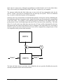

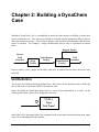

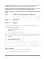

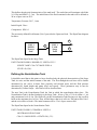
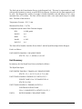
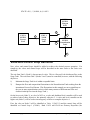

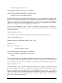
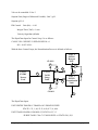
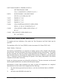
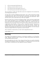
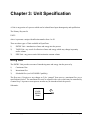
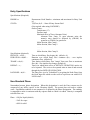
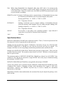
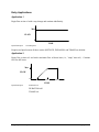


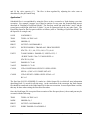

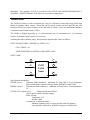
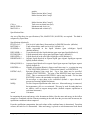

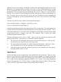
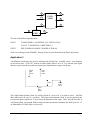

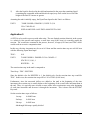

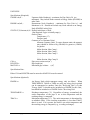
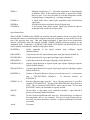

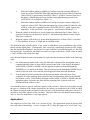

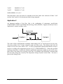
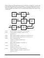
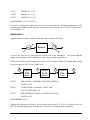
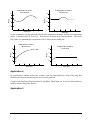
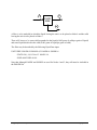
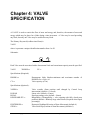


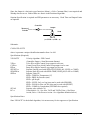


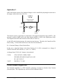
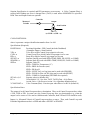

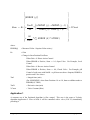
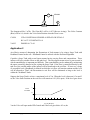
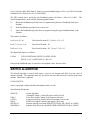

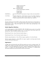
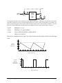
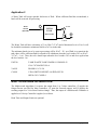


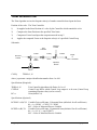

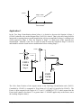


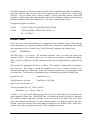


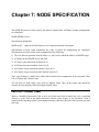

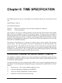


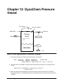
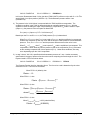
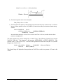

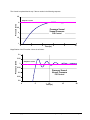
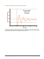
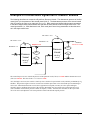
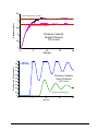
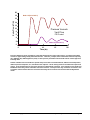
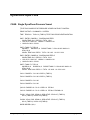


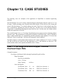
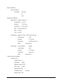
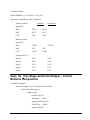
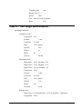
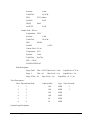


![カービィー バーチカルタイプ 取扱説明書[PDF]](http://vs1.manualzilla.com/store/data/006655008_2-64046adb3e1f5cb8dce1b07f529301a4-150x150.png)