1
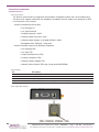
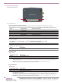
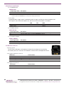
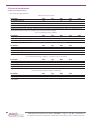
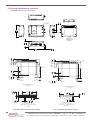
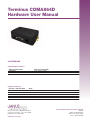
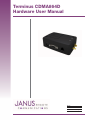
Terminus CDMA864D
Hardware User Manual
Bulletin
Revision
Date
JA06-UM
R01
16 July 2012
TABLE OF CONTENTS
1 DISCLAIMER........................................................................................................................................................................ 3
2 REFERENCES...................................................................................................................................................................... 4
2.1 Telit Document List
3 OVERVIEW......................................................................................................................................................................... 4-5
3.1 Introduction................................................................................................................................................................ 4
3.2 Functional Description............................................................................................................................................... 4
3.2.1 Connectors...................................................................................................................................................... 4
3.2.2 Block Diagram................................................................................................................................................. 5
3.3 Features..................................................................................................................................................................... 5
3.3.1 CDMA Features
4 INTERFACES................................................................................................................................................................... 6-12
4.1 Serial Interface Connector......................................................................................................................................... 6
4.1.1 Description
4.1.2 Pin-out
4.1.3 Signal Interface Description
4.2 USB Interfaces........................................................................................................................................................... 7
4.2.1 USB Port
4.2.2 USB Connection Diagram
4.3 Power Supply............................................................................................................................................................. 7
4.3.1 Description
4.3.2 Pin-out
4.3.3 Power Supply Interface
4.4 Audio Interface........................................................................................................................................................... 8
4.4.1 Description
4.4.2 Pin-out
4.4.3 Signal Description
4.5 Embedded Interace.............................................................................................................................................. 9-11
4.5.1 Description
4.5.2 Pin-out
4.5.3 Signal Description
4.5.4 Signal Details
4.5.4.1 General Purpose Input / Output
4.5.4.2 Analog to Digital Converter
4.5.4.3 Reset Pin
4.5.4.4 ON/OFF Pin
4.5.4.5 PWRMON Pin
4.5.4.6 UART_SEL Pin
4.6 LED Status Indicators.............................................................................................................................................. 11
4.6.1 Description
4.6.2 Cellular LED Status (Yellow)
4.6.3 Application (Green)
4.7 RF Interface............................................................................................................................................................. 12
4.7.1 Description
4.7.2 Cellular Antenna
4.7.2.1 Cellular Antenna Interface
4.7.2.2 Cellular Antenna Specifications
4.7.3.3 Sprint Certified Antenna
4.7.2.4 Cellular Antenna Installation Guidelines
4.8 GPS Antenna........................................................................................................................................................... 13
4.8.1 GPS Antenna Interface
4.8.2 GPS Active Antenna Specifications
4.8.3 GPS Antenna Installation Guidelines
JA06-UM Terminus Hardware User Guide - CDMA864D
Page 2
Rev: R01
Date: 07/16/12
© Copyright 2012 Janus Remote Communications All Rights Reserved Specifications subject to change without notice
5 TECHNICAL SPECIFICATIONS..................................................................................................................................... 14-15
5.1 Electrical Specifications...................................................................................................................................... 14-15
5.1.1 I/O Level Specifications
5.1.2 Terminus Electrical Specifications
5.2 Mechanical Dimensions........................................................................................................................................... 16
6. AT Command Guidelines.................................................................................................................................................. 17
6.1 AT Command Format............................................................................................................................................... 17
6.2 AT Command Example............................................................................................................................................ 17
7. OPERATION.................................................................................................................................................................. 18-25
7.1 Setting Up a Terminal Emulator for use with the Terminus...................................................................................... 18
7.2 Powering ON/OFF................................................................................................................................................... 18
7.3 Setting Up Network Services.............................................................................................................................. 18-22
7.3.1 Sprint Provisioning
7.3.2 Verizon Provisioning
7.3.3 CrossBridge Provisioning
7.4 Making a Voice Call................................................................................................................................................. 22
7.5 Sending an SMS...................................................................................................................................................... 23
7.6 Establishing a Socket Connection........................................................................................................................... 23
7.7 GPS......................................................................................................................................................................... 24
7.7.1 GPS via USB
7.7.2 GPS retrieval from the COM port
7.8 Additional Instructions............................................................................................................................................. 25
8. Appendices............................................................................................................................................................... 26-27
8.1 Approvals................................................................................................................................................................. 26
8.2 Safety....................................................................................................................................................................... 26
8.3 Abbreviations........................................................................................................................................................... 26
8.4 Ordering Information................................................................................................................................................ 27
8.5 Revision History....................................................................................................................................................... 27
1 DISCLAIMER
The information contained in this document is the proprietary information of Connor-Winfield Corporation and its affiliates (Janus Remote Communication). The contents are confidential and any disclosure to persons other than the officers, employees, agents or subcontractors of the owner or licensee of this document, without the prior written consent of Connor-Winfield, is strictly prohibited.
Connor-Winfield makes every effort to insure the quality of the information it makes available. Notwithstanding the foregoing, Connor-Winfield does not make any warranty as to the information
contained herein, and does not accept any liability for any injury, loss or damage of any kind incurred by use of or reliance upon the information. Connor-Winfield disclaims any and all responsibility for
the application of the devices characterized in this document, and notes that the application of the device must comply with the safety standards of the applicable country, and where applicable, with
the relevant wiring rules. Connor-Winfield reserves the right to make modifications, additions and deletions to this document due to typographical errors, inaccurate information, or improvements to
programs and/or equipment at any time and without notice. Such changes will, nevertheless be incorporated into new editions of this application note.
All rights reserved 2010 Connor-Winfield Corporation
JA06-UM Terminus Hardware User Guide - CDMA864D
Page 3
Rev: R01
Date: 07/16/12
© Copyright 2012 Janus Remote Communications All Rights Reserved Specifications subject to change without notice
2 REFERENCES
2.1 Telit Document List
Please refer to Telit’s website at www.telit.com for the latest information on the CC864-DUAL module.
2.1.1
CC864 Hardware User Guide
2.1.2
CC864 Software User Guide
2.1.3
AT Commands Reference Guide
3 OVERVIEW
3.1 Introduction
The Terminus CDMA864D is a self-contained, dual-band CDMA/1xRTT terminal device designed to provide a
comprehensive solution to application problems for our M2M customers. It utilizes the proven technology
of the Telit CC864-DUAL module for its core communications engine as well as the Dual-Mode GPS receiver
(standalone and gpsOne) for the added flexibility of GPS.
3.2 Functional Description
3.2.1 Connectors
Access Panel for
On/Off Button
50-Pin Header
MCX Connector
for
GPS Receiver
SMA Connector
for
Cellular Input
Antenna Connectors
JA06-UM Terminus Hardware User Guide - CDMA864D
Page 4
Rev: R01
Date: 07/16/12
© Copyright 2012 Janus Remote Communications All Rights Reserved Specifications subject to change without notice
3 OVERVIEW continued
3.2.2 Block Diagram
CDMA864D
UART
UART
TRACE
ENABLE
RS-232
CPLD
UART
DB9
UART
TRACE
UART SELECT
TELIT
CC864-DUAL
CDMA/1xRTT
ON/OFF
SUPERVISOR
ON/OFF'
ON/OFF
RESET
PWRMON
50-Pin
Header
VAUX
GPIO (1 - 7)
ADC1
USB
ENABLE
3.8V
Switcher
HANDS-FREE AUDIO PATH
Protection
SUPPLY +
AUDIO
BARREL
3.3 Features
3.3.1 CDMA Features
• Dual-band CDMA 800 / 1900 MHz
• Air interface IS-95A/B and CDMA 2000
• 1xRTT Data up to 153.6Kbps (full duplex)
• TCP/IP stack access via AT commands
• Over-the-Air firmware management
• Voice and SMS (MO / MT)
• Full voice support includes Supplementary Services
• Output power
• 24.3 dBm (270mW)
• Sensitivity:
• -108 dBm (typ.) @ 800 MHz
• -108 dBm (typ.) @ 1900 MHz
• Operational temperature range: -30°C to 80°C
• Dimensions: 2.5 x 1.4 x 0.415”
• Internal switching regulator
• Input Voltage range: 7 to 18Vdc
(12.0Vdc Nominal)
• Supply disable via terminal input pin
• Cellular and GPS available via Murarta GSC miniature
RF connector
• GPS
• Stand-alone GPS available at AT command
interface
• GpsOne® (User and Control plane)
• NMEA Data
• GPS fix on Demand
• Dedicated GPS antenna connection with active
antenna support
JA06-UM Terminus Hardware User Guide - CDMA864D
Page 5
Rev: R01
Date: 07/16/12
© Copyright 2012 Janus Remote Communications All Rights Reserved Specifications subject to change without notice
4 INTERFACES
4.1 Serial Interface Connector
4.1.1 Description
The Terminus serial interface is an RS-232 port that supports both EIA/TIA-232 and V.28/V.24 communications
protocols. It accepts a standard RS-232 Sub-D, 9-pin male plug. Communications settings for this port are as
follows:
•
•
•
•
•
Baud Rate: 115.2kbps
Bits: 8
Stop Bits: 1
Parity: none
Hardware Handshaking: Yes
4.1.2 Pin-Out
Pin
1
2
3
4
5
6
7
8
9
Description
I/O
Signal Type
Carrier Detect (CD)
Received Data (RxD)
Transmitted Data (TxD)
DTE Ready (DTR)
Signal Ground
DCE Ready (DSR)
Request to Send (RTS)
Clear to Send (CTS)
Ring Indicator (RI)
OUTPUT
OUTPUT
INPUT
INPUT
N/A
OUTPUT
INPUT
OUTPUT
OUTPUT
RS-232
RS-232
RS-232
RS-232
N/A
RS-232
RS-232
RS-232
RS-232
4.1.3 Signal Interface Description
6) DSR 7) RTS 8) CTS 9) RI
1) CD 2) RxD 3)TxD 4) DTR 5) GND
JA06-UM Terminus Hardware User Guide - CDMA864D
Page 6
Rev: R01
Date: 07/16/12
© Copyright 2012 Janus Remote Communications All Rights Reserved Specifications subject to change without notice
4 Interfaces continued
4.2 USB Interfaces:
4.2.1USB Port
The CDMA864D Terminal includes an integrated universal serial bus (USB) transceiver, compliant with USB 2.0
specifications and supporting the USB Full-Speed (12 Mb/s) mode. The CMDA864D includes all active and
passive components to implement the USB function and the user only need add a USB connector external to
5
4
3
2
1
the
Terminal.
Note: You must have access to the USB interface in order to locally update radio firmware for the embedded CDMA module.
4.2.2 USB Connection Diagram
D
D
INTERNAL CDMA864D TERMINAL COMPONENTS
4
5
2
6
USB_VBUS
t
PTC 200mA (0805L020YR)
1
U12
ESD ARRAY (RCLAMP0504F.TCT)
S-574-G
C
10uF, 20%
25V
3
2
1
C
USB-TYPE B SOCKET (www.samtec.com)
USB-B-S-F-B-TH
50-PIN HEADER (VBUS)
50-PIN HEADER (USB_D-)
50-PIN HEADER (USB_D+)
50-PIN HEADER (SUPPLY GROUND)
27, 5%
USB_DUSB_D+
1
2
3
4
27, 5%
6
5
B
B
4.3 Power Supply
4.3.1 Description
The Terminus Power Supply jack accepts input voltages from 7 to 18 VDC and requires a nominal current
sourcing capacity of 5W (maximum 10W). This jack accepts a barrel type plug with a receptacle for a 2.1mm
center conductor.
The Terminus is equipped with protection circuitry to prevent reverse voltage, as well as help with protection A
from transients.
Title
Janus Recommended USB Connection
The Terminus can withstand a reverse voltage of-60V and a peak voltage of 80V. The circuitry is set to clip any
Size
Document Number
Rev
0
input greater than 26V to a safe level. Any input above 26V will readA for <Doc>
a set period, and if before 20 mS it hasn’t
Date:
Sheet
Tuesday, August 31, 2010
1
of
1
returned
to
safe
level,
the
over-voltage
protection
will
activate
and
turn
off
the
output.
5
4
3
2
1
To re-enable the output, power must be cycled or the ENABLE_SUPPLY pin (pin 39) must be pulled low at least
100 µS and then released.
A
4.3.2 Pin Out
Pin
Description
Center Pin
Outer Conductor
Supply (+)
Supply (-)
4.3.3 Power Supply Interface
(-)
(+)
JA06-UM Terminus Hardware User Guide - CDMA864D
Page 7
Rev: R01
Date: 07/16/12
© Copyright 2012 Janus Remote Communications All Rights Reserved Specifications subject to change without notice
4 Interfaces continued
4.4 Audio Interface
4.4.1 Description
The Terminus audio interface is designed to accommodate a telephone handset with a 4P4C modular plug.
The input circuit supports a balanced, low-impedance microphone and can supply a bias voltage of 3.0 VDC.
Its characteristics are as follows:
Hands Free Audio Input Circuit (Mic)
• Line Coupling: AC
• Line Type: Balanced
• Coupling Capacitor: ≥100nF
• Differential Input Resistance: 20kΩ
• Differential Input Voltage: ≤1,03 Vpp@ HFMICG = 0 dB)
• Microphone Gain: TDB/step, 7 steps total
Hands Free Audio Output Circuit (Earpiece or Speaker)
• Line Coupling: TBD
• Line Type: TBD
• Output Load Resistance: TBD
• Frequency Response: TBD
• Differential Output Voltage: TBD
• Software Volume Control: TBD step, 6 steps total (AT#HFRECG)
4.4.2 Pin-Out
Pin
Description
1
2
3
4
Microphone (-)
Earphone (-)
Earphone (+)
Microphone (+), 3.0Vdc nominal supplied by Terminus to power handset.
4.4.3 Signal Description
JA06-UM Terminus Hardware User Guide - CDMA864D
Page 8
Rev: R01
Date: 07/16/12
© Copyright 2012 Janus Remote Communications All Rights Reserved Specifications subject to change without notice
4 Interfaces continued
4.5 Embedded Interface
4.5.1 Description
The Embedded Interface is a 50 pin dual row header that allows a user to access many of the available ports and
features of the Terminus through a single interface. The connector is located on the bottom of the unit such that
it can be integrated with an application PC board. A ribbon cable with a tabbed header connector such as the
Samtec HCSD-25-D-1 can also be used. This interface can be functionally divided up into the following groups:
General Purpose I/O interface, the ADC interface and Terminus Control interface. The pin designations and
specifications for this interface are shown below.
4.5.2 Pin-Out
PIN
DESCRIPTION
5,7,9,11,13,15,17,19,21,23,25,40,42,44,46,48,50 SUPPLY GROUND
41,43,45,47,49
SUPPLY +
39
SUPPLY ENABLE
35
RESET
33
ON/OFF
31
PWRMON
29
UART SELECT
37
VAUX
38
GPIO1
36
GPIO2
34
GPIO3
32
GPIO4
30
GPIO5
28
GPIO6
26
GPIO7
27
ADC1
24
DCE Ready (DSR)
22
Clear to Send (CTS)
20
Ring Indicator (RI)
18
Carrier Detect (CD)
16
DTE Ready (DTR)
14
Request to Send (RTS)
12
Received Data (RxD)
10
Transmitted Data (TxD)
8
TRACE TX
6
TRACE RX
4
USB D+
2
USB D-
3
USB ID (FUTURE USE)
1
USB VBUS
I/O
-
-
INPUT
INPUT
INPUT
OUTPUT
INPUT
OUTPUT
BI-DIR
BI-DIR
BI-DIR
BI-DIR
BI-DIR
BI-DIR
BI-DIR
INPUT
OUTPUT
OUTPUT
OUTPUT
OUTPUT
INPUT
INPUT
OUTPUT
INPUT
OUTPUT
INPUT
BI-DIR
BI-DIR
-
-
SIGNAL TYPE
PULL
NOTE
-
-
-
-
-
UP (SUPPLY +) -
UP
1
-
UP
1
2.6V CMOS
-
3.3V CMOS
UP
1
ANALOG 2.6V
-
2.6V CMOS
-
2.6V CMOS
-
2.6V CMOS
-
2.6V CMOS
-
2.6V CMOS
-
2.6V CMOS
-
2.6V CMOS
-
ANALOG
-
3.3V CMOS
-
2
3.3V CMOS
-
2
3.3V CMOS
-
2
3.3V CMOS
-
2
3.3V CMOS
-
2
3.3V CMOS
-
2
3.3V CMOS
-
2
3.3V CMOS
-
2
3.3V CMOS
-
3.3V CMOS
-
5.0V CMOS
-
5.0V CMOS
-
-
-
3, 4
-
-
-
Notes:
1.) It is required that this input be controlled by an Open Collector/Drain output. Do not use an external pull-up resistor, a pull-up is included
internal to the Terminus.
2.) According to V.24, the RXD and TXD signals are referred to from the perspective of the application. Therefore, these signals are referred to in
the opposite direction for the module. Transmitted Data (TxD) is an input and Received Data (RxD) is and Output.
3.) Not currently implemented. USB On The Go, Analog input used to sense whether a peripheral device is connected and determine the
peripheral type; a host or a peripheral.
4.) Do not connect.
JA06-UM Terminus Hardware User Guide - CDMA864D
Page 9
Rev: R01
Date: 07/16/12
© Copyright 2012 Janus Remote Communications All Rights Reserved Specifications subject to change without notice
4 Interfaces continued
4.5.3 Signal Description
Bottom View
Pin 1
Pin 49
Pin 2
Pin 50
4.5.4 Signal Details
4.5.4.1 General Purpose Input / Output
Terminus GPIO are configurable as input, output, and special function. Configuration is controlled by the Customer
specific application via AT commands sent on the UART interface. The following table describes GPIO configuration options.
GPIO
1
2
3
4
5
6
7
Configuration
Alternate Function
Input / Output
Input / Output
Input / Output
Input / Output
Input / Output Input / Output
Input / Output RFTX monitor output
alarm output
buzzer output
4.5.4.2 Trace TX/RX
The diagnostics monitoring port, used for debug and firmware updates of the radio.
RX_TRACE
TX_TRACE
In RX Data for debug monitor
Out TX Data for debug monitor
4.5.4.3 Analog to Digital Converter
ADC
Description
1
Analog to Digital Converter Input
4.5.4.4 Reset Pin
RESET PIN:
Input Logic State
Description
High-Z
0
Terminus Active State
Terminus Reset State
Notes: 1. It is required that this input be controlled by an Open Collector/Drain output. Do not use an external pull-up resistor, a pull-up is included
internal to the Terminus.
2 The RESET pin is offered as a means to reset the Terminus when and if the Terminus becomes unresponsive. The RESET pin is not
intended to be used as a means of turning the Terminus off. Use the ON/OFF pin to turn the Terminus on or off.
3. RESET state must be held for at least 200ms before returning to active state.
4.5.4.5 ON/OFF Pin
ON/OFF PIN:
Input Logic State
Description
High-ZTerminus turned ON or OFF after Input returns to this state.
0Toggle Terminus ON or OFF
Notes: 1. It is required that this input be controlled by an Open Collector/Drain output. Do not use an external pull-up resistor, a pull-up is
included internal to the Terminus.
2. The ON/OFF pin is offered as a means to power-on and power-down the Terminus. When the Terminus powers-down it informs the cell
tower that it is powering down and will not be communicating with the tower any more. This is considered a controlled power-down.
3. After toggling the power state of the Terminus, wait until PWRMON indicates chosen state before toggling the power state again.
4. Optionally the Terminus may be powered-down with the use of AT commands.
JA06-UM Terminus Hardware User Guide - CDMA864D
Page 10
Rev: R01
Date: 07/16/12
© Copyright 2012 Janus Remote Communications All Rights Reserved Specifications subject to change without notice
4 Interfaces continued
4.5.4.6 PWRMON Pin
PWRMON PIN:
Output Logic StateDescription
0
1
Terminus powered-down
Terminus powered-on
Notes:
1. Used in conjunction with ON/OFF pin to control power-on and power-down state.
4.5.4.7 VAUX
A regulated power supply output is provided in order to supply small devices from the module itself.
This output is active when the module is on, and shuts off when the module is shut down.
MIN
TYP.
Output voltage
2.62V
2.65V
Output current
MAX
2.68V
150mA
4.5.4.8 UART_SEL Pin
UART_SEL PIN:
Input Logic State
Description
1Terminus UART interface routed to DB9 connector (Internally pulled high)
0Terminus UART interface routed to EMBEDDED connector
4.5.4.9 SUPPLY ENABLE
SUPPLY_ENABLE:
Input Logic State
Description
1
0
Power circuit enabled (internally pulled high))
Power circuit disabled
Note: Used if an overvoltage or overcurrent fault has occured.
4.6 LED Status Indicators
Status
Indicator
4.6.1 Description
The LED Status Indicators are located on the top of the housing near the end where
the antenna jacks are. There are 2 LED indicators; Cellular Status and Application Status.
APP
LED
Cellular
LED
4.6.2 Cellular LED Status (Yellow)
LED StatusDevice Status
Permanently Off
Fast Blinking (Period 1s, ton 0.5s)
Slow Blinking (Period 3s, ton 0.3s)
Permanently On
Device Off
Net search/ Not registered/Turning Off
Registered, Full Service
A call is active
4.6.3 Application (Green)
LED StatusDevice Status
OFF
ON
User Defined AT#GPIO=21,0,1
User Defined AT#GPIO=21,1,1
JA06-UM Terminus Hardware User Guide - CDMA864D
Page 11
Rev: R01
Date: 07/16/12
© Copyright 2012 Janus Remote Communications All Rights Reserved Specifications subject to change without notice
4 Interfaces continued
RF
Interface
4.7 RF Interface
4.7.1 Description
There are two RF interfaces on the Terminus – the cellular antenna jack and the GPS
antenna jack. The specifications and requirements for these are as follows:
4.7.2 Cellular Antenna
APP Cellular
Jack Jack
4.7.2.1 Cellular Antenna Interface:
Type:
SMA - FEMALE
Pin
Description
Center PinCellular Signal
Outer ConductorSIGNAL Ground
4.7.2.2 Cellular Antenna Specifications
ParameterDescriptions
Frequency range (CDMA)Tx: 824MHz – 849 Mhz
Rx: 869Mhz – 894 MHz
Frequency range (PCS)Tx: 1850 MHz – 1910 MHz
Rx: 1930 MHz – 1990 MHz
Frequency range (GPS) 1575.42 MHz
Impedance
50 Ohm
Recommended VSWR
<2
Radiation Pattern
Omni-directional
Polarization
Vertical
4.7.2.3 Sprint Certified Antenna
Janus Remote Communications Part Number ANT-0073-G
Frequency: 824-894 MHz, 1850-1990 MHz
Gain: 3 dBi
VSWR: 2:1 Max
Impedance: 5W Max
Operating Temperature: -40°C to 85°C
Length: 6.75” with 90° angle; 7.75” when straight
4.7.2.4 Cellular Antenna Installation Guidelines
1. Install the antenna in a place covered by the Cellular signal.
2. The Antenna must be installed to provide a separation distance of at least 20 cm from all persons and must
not be co-located or operated in conjunction with any other transmitting antenna.
3. Antenna shall not be installed inside metal cases.
4. Antenna shall be installed according to manufacturer instructions.
Caution: DO NOT OVER-TIGHTEN ANTENNAS. Do not exceed 5 in.lbs force as over-tightening may damage the unit.
JA06-UM Terminus Hardware User Guide - CDMA864D
Page 12
Rev: R01
Date: 07/16/12
© Copyright 2012 Janus Remote Communications All Rights Reserved Specifications subject to change without notice
4 Interfaces continued
4.8 GPS Antenna
4.8.1 GPS Antenna Interface
Type:
MCX - FEMALE
Pin
Description
Center PinGPS Signal, 3.4 to 4.2 Vdc nominal supplied from Terminus to power active antenna.
Outer Conductor
Signal ground
.
4.8.2 GPS Active Antenna Specifications:
Parameter
Value
Frequency range
Bandwidth
Gain
Impedance
Amplification
Supply voltage
Current consumption
1575.42 MHz (GPS L1)
± 1.023 MHz
1.5 dBi < Gain < 4.5 dBi
50 ohm
12 dB – 16 dB
Must accept from 3 to 5 VDC
20 mA Typical (40 mA max)
4.8.3 GPS Antenna Installation Guidelines
1. Install the antenna with a clear sky view.
2. Antenna shall not be installed inside metal cases.
3. Antenna shall be installed also according to Antenna manufacturer instructions.
JA06-UM Terminus Hardware User Guide - CDMA864D
Page 13
Rev: R01
Date: 07/16/12
© Copyright 2012 Janus Remote Communications All Rights Reserved Specifications subject to change without notice
5 Technical Specifications
5.1 Electrical Specifications
5.1.1 I/O Level Specification
Absolute Maximum Ratings
Parameter
Min
Typ
Max
Unit
VIN (DIGITAL INPUTS)
VIN (ANALOG INPUT)
Storage Temperature
Recommended Operating Temperature
Supply (+) Referenced to Supply(-)
-0.3
-0.3
-40
-30
5
-
-
-
-
-
2.9
2.6
85
85
24
Volt
Volt
°C
°C
V
Note
Operation of the device at these or any other conditions beyond those listed under Recommended Operating Conditions is not implied. Exposure to
Absolute Maximum Rating conditions for extended periods of time may affect device reliability.
Recommended Operating Conditions
Parameter
Min
Typ
Max
Unit
Note
Temperature
Supply (+) Referenced to Supply (-)
VAUX Output
-30
7
2.62
-
-
-
80
18
2.65
°C
Volt
Volt
8
1
2
Recommended Operating Conditions - Interface Levels (2.6V CMOS)
Parameter
Min
Typ
Max
Unit
Input Voltage High - Vih
Input Voltage Low - Vil
Output Voltage High - Voh
Output Voltage Low - Vol
1.69
0.3
2.15
0
-
-
-
-
2.9
0.91
2.6
0.45
Volt
Volt
Volt
Volt
Typical Current Source/Sink capability = 1mA/1uA
Recommended Operating Conditions – Interface Levels (3.3V CMOS)
Parameter
Min
Typ
Max
Unit
Input Voltage High - Vih
Input Voltage Low - Vil
Output Voltage High - Voh
Output Voltage Low - Vol
2.0
-0.3
2.7
-
-
-
-
-
3.9
0.8
3.5
0.4
Volt
Volt
Volt
Volt
Typical Current Source/Sink capability = 1mA/1uA
Recommended Operating Conditions - RESET pin
Parameter
Min
Typ
Max
Unit
Input Voltage High - Vih_rst
Input Voltage Low - Vil_rst
2.0
0
-
-
2.6
0.2
Volt
Volt
It is required that this input be controlled by an Open Collector/Drain output. Do not use an external pull-up resistor, a pull-up is included internal
to the Terminus.
JA06-UM Terminus Hardware User Guide - CDMA864D
Page 14
Rev: R01
Date: 07/16/12
© Copyright 2012 Janus Remote Communications All Rights Reserved Specifications subject to change without notice
5 Technical Specifications
5.1 Electrical Specifications continued
USB Transceiver Specifications
Parameter
Comments
Min
Typ
Max
Unit
USB_VBUS
Supply Voltage
4.5
5.0
5.25
V
Supply Current
11.7
15
mA
Termination Voltage
An internal supply voltage VTRM
3.0
3.3
3.6
V
USB_D+, DInput sensitivity
ID+ - D-I
0.2
V
(differential)
Output Voltage
Logic LOW
R, = 1.5kW to 3.6V 0.3
V
Logic HIGH
R, = 15kW to GND, 1o=1mA 2.8 3.6
Input Voltage
Logic LOW
R, = 1.5kW to 3.6V 0.3
Logic HIGH
R, = 15kW to GND, 1o=1mA
3.0 3.6
Internal pull-up resistor
VTRM to D+, V TRM to D-
1.425
1.5
1.575
kW
Internal pull-down resistor
D+ to GND, D- to GND
14.3
15
24.8
kW
V
V
V
Recommended Operating Conditions - ADC1 pin
Parameter
Min
Typ
Max
Unit
Input Voltage Range
AD Conversion
Conversion Time
0
-
-
-
-
-
2.5
8
15.4
Volt
Bits
µS
Min
Typ
Max
Unit
12
11
28
220
100
-
18
-
-
-
-
10
Vdc
mA mA
mA
mA
Watts
5.1.2 Terminus Electrical Specifications
Power Supply
Voltage Range
7
Average Current (Registered, Power Savings) with GPS disabled
Average Current (Registered, No Traffic) with GPS disabled
-
Average Current (Max level, 23-24 dBm) with GPS disabled
-
Average Current (Min level, -50 dBm) with GPS disabled
-
Power
-
JA06-UM Terminus Hardware User Guide - CDMA864D
Page 15
Rev: R01
Note
Date: 07/16/12
© Copyright 2012 Janus Remote Communications All Rights Reserved Specifications subject to change without notice
5 Technical Specifications continued
5.2 CDMA864D Mechanical Dimensions
2x Hole
for
#6 SHCS
.650
16.51
2.600
66.04
Bottom View
w/ Bottom Cover
Removed
1.214
30.84
3.750
95.25
.313
7.95
2.600 66.04
2.369 60.18
2.357 59.86
2.600 66.04
PIN 1
2.369 60.18
2.304 58.52
2.152 54.65
2.143 54.44
2.050 52.07
2.204 55.98
2.143 54.44
Pin 1
2.050 52.07
.550 13.97
.550 13.97
0 0
Mechanical Dimensions
(Top View)
.070 1.78
Mechanical Dimensions
(Top View)
2.400 60.96
2.400 60.96
Pin #50
Pin #2
Pin #49
Pin #1
Pin #2
Pin #49
Pin #1
.040 1.02
.100 2.54
.100 2.54
Pad Dimensions for
recommended connector,
Samtec P/N SSW-125-22-S-D-VS
(Top View)
Recommended Surface Mount Footprint
.100 2.54
Pin #50
.050 1.27
.340 8.64
3.750 95.25
3.075 78.11
3.228 82
3.375 85.73
.675 17.15
.375 9.53
.140 3.56
2x
(Clearance for a
#6 SHCS
.522 13.25
0 0
3.750 95.25
3.228 82
3.375 85.73
3.075 78.11
.675 17.15
.522 13.25
0 0
.375 9.53
0 0
.140 3.56
2x
(Clearance for a
#6 SHCS)
Hole Dimensions for
recommended connector,
Samtec P/N SSQ-125-01-S-D
(Top View)
Recommended Thru-Hole Footprint
JA06-UM Terminus Hardware User Guide - CDMA864D
Page 16
Rev: R01
Date: 07/16/12
© Copyright 2012 Janus Remote Communications All Rights Reserved Specifications subject to change without notice
6. AT COMMAND GUIDELINES
The basic AT commands used to control Terminus operation are defined in this section. Please refer to Telit AT
Command Guide for detailed command definition.
6.1 AT Command Format
A command line is a string of characters sent from a DTE or emulation software to the Terminus while the modem is in
a command state. A command line has a prefix, a command, and a terminator. Each command line must begin with the
character sequence AT and must be terminated by a carriage return and line feed (ie ASCII Carriage Return <13> and ASCII
LineFeed <10>). Commands entered in upper case or lower case are accepted, but both the A and T must be of the same
case, i.e., “AT” = ASCII 065, 084 or “at” = ASCII 097, 116. The command is a string of commands restricted to printable ASCII
characters (032 - 126). Standardized commands start with a “+” character and proprietary commands can start with one of
the following characters, “@”, “#”, “$” or “*”. Space characters (ASCII 032) in a command are ignored and control characters
other than defined terminator characters CR (ASCII 013) and LF (ASCII 010) in the command string will cause an ERROR
result code. The default terminator is the ASCII <CR> character followed by the ASCII <LF> character. The command line
interpretation begins upon receipt of the carriage return and line feed characters.
If a syntax error is found anywhere in a command line command, the remainder of the line will be ignored and the ERROR
result code will be returned.
Most commands entered with parameters out of range will not be accepted and the ERROR response will be returned to the
DTE or emulation software.
Commands will only be accepted by the modem once the previous command has been fully executed, which is normally
indicated by the return of an appropriate result code.
6.2 AT Command Example
Example AT Commands
AT$QCMIPP=1
AT&P0<cr><lf>
// select NAI Profile 1
//save profile
JA06-UM Terminus Hardware User Guide - CDMA864D
Page 17
Rev: R01
Date: 07/16/12
© Copyright 2012 Janus Remote Communications All Rights Reserved Specifications subject to change without notice
7. OPERATION
7.1 Setting Up a Terminal Emulator for use with the Terminus
7.1.1 To interface with the Terminus connect the Serial Interface RS-232 port to a PC and use a terminal
emulation program such as Microsoft® Hyperterminal. Set the interface parameters as follows:
• Baud Rate: 115.2 kbps
• Bits: 8
• Stop Bits: 1
• Parity: None
• Hardware Handshaking: Yes
7.1.2 Test Terminal Emulator Setup
• Enter AT<cr> from terminal and wait for OK
Note that Autobaud is not supported on the CDMA864D Terminus. While utilizing the RS-232 port, if you wish to change the baud rate on the
module you must use AT+IPR. You must also change the rate in the host UART (i.e. HyperTerminal) to match the new baud rate. If these do not
match you will not be able to send AT commands to the module through the serial port.
7.2 Powering ON/OFF
7.2.1The Terminus is turned ON automatically once DC power is applied. If the Terminus is turned OFF using
one of the methods described below, it can be turned back ON again through one of two methods:
• Pull ON/OFF signal (pin 33 of 50 pin straight header) to ground, then release.
• Press the ON/OFF switch, then release
The Terminus is fully operational after 4 seconds. Logging onto a network may take longer than this and
is outside the control of the Terminus.
7.2.2 There are three ways to switch OFF the Terminus as described below.
• Use the appropriate AT command (AT#SHDN)
• Pull ON/OFF signal to ground, then release
• Press ON/OFF switch (SW1), then release
7.3 Setting Up Service
7.3.1 Sprint Provisioning
7.3.1.1 Sprint Account Set-up
Contact Sprint or Sprint MVNO to set-up a service contract.
You will need to have the following information to set-up service.
Product Model Number:
Product Manufacture:
MEID #:
CDMA864D V2.00
Janus Remote Communications
Issue AT command: AT#MEID?
Contact information
Contact: Dave Jahr, Janus Remote Communications
[email protected]
630-499-2121
JA06-UM Terminus Hardware User Guide - CDMA864D
Page 18
Rev: R01
Date: 07/16/12
© Copyright 2012 Janus Remote Communications All Rights Reserved Specifications subject to change without notice
7. OPERATION continued
7.3.1 Sprint Provisioning continued
7.3.1.2 Verify Provisioning
After receiving verification that your service has been activated you will need to verify that your Terminal has been
provisioned. To determine if your Terminal has been provisioned to work with the Sprint network you need to review the
current profile settings.
Issue AT command:
AT$QCMIPGETP
Response:
Profile:0 Enabled
NAI:[email protected]
Home Addr:0.0.0.0
Primary HA:68.28.15.12
Secondary HA:68.28.31.12
MN-AAA SPI:1234
MN-HA SPI:1234
Rev Tun:1
MN-AAA SS:Set
MN-HA SS:Set
A terminal not provisioned will have the following characteristics.
Profile:0 Enabled
NAI: [email protected]
A terminal provisioned will have the following characteristics.
Profile :1 Enabled
NAI: [email protected]
Upon power up, the module will attempt to provision itself if not already done. It will continue to attempt this until it is successful.
7.3.2 Verizon Provisioning
7.3.2.1 Verizon Account Set-up
Contact Verizon or Verizon MVNO to set-up a service contract.
You will need to have the following information to set-up service.
1. Product Model Number: CDMA864D V3.00
2. Product Manufacture: Janus Remote Communications
3. MEID #: Issue AT command: AT#MEID?
Contact information
Contact: Dave Jahr, Janus Remote Communications
[email protected]
630-499-2121
JA06-UM Terminus Hardware User Guide - CDMA864D
Page 19
Rev: R01
Date: 07/16/12
© Copyright 2012 Janus Remote Communications All Rights Reserved Specifications subject to change without notice
7. OPERATION continued
7.3.2 Verizon Provisioning continued
7.3.2.2 Verizon Provisioning
•Issue the following command and ensure you have a “2” in the bolded/red location:
09.01.0Xx
AT+CGMR
•Ensure the module is registered on the network.
Enter AT+CREG? and wait for response +CREG: 0,1
•Verify profile :0 is selected and enabled.
Enter AT$QCMIPP? and verify response $QCMIPP: 0
Enter AT$QCMIPEP? and verify response $QCMIPEP: 1
This profile is required to be active during Verizon provisioning.
•Send command “ATD*22899;” and wait for response OK
Wait for response #OTASP:0
Wait for response #OTASP:1
Wait for response #OTASP:2
If you receive a response #OTASP:5, or do not receive #OTASP:1 and #OTASP:2, the provisioning has failed somewhere.
Please verify that your account has been set up, activated, and that you have been given an MDN and MSID for your module’s
MEID/ESN.
•Send command AT#SGACT=1,1 and wait for a response #SGACT:XXX.XXX.XXX.XXX
•Wait 10-15 seconds and send command AT#SGACT=1,0. Wait for response OK.
Please Note that AT#SGACT=1,1 being entered with a proper IP address response is required to complete provisioning
on Verizon. Do not skip this step.
7.3.3 CrossBridge Provisioning
7.3.3.1 CrossBridge Account Set Up
Contact CrossBridge to set-up a service contract.
You will need to have the following information to set-up service.
1. Product Model Number: CDMA864D V2.00
2. Product Manufacture: Janus Remote Communications
3. MEID #: Issue AT command: AT#MEID?
Contact information
Contact: Dave Jahr, Janus Remote Communications
[email protected]
630-499-2121
When the ESN has been activated, you should receive information on the module, which includes the following:
1. The module’s 10 digit MDN.
2. The module’s 10 digit MSID.
3. The module’s NAI, in a form similar to <MSID>@spp106.dl.sprintpcs.com.
4. The password associated to the NAI <pw>.
5. The Primary Home Address <pha>
6. The Secondary Home Address <sha>
7. The HA-SS
JA06-UM Terminus Hardware User Guide - CDMA864D
Page 20
Rev: R01
Date: 07/16/12
© Copyright 2012 Janus Remote Communications All Rights Reserved Specifications subject to change without notice
7. OPERATION continued
7.3.3 CrossBridge Provisioning continued
7.3.3.2 CrossBridge Provisioning
•Ensure the module is registered on the network.
AT+CREG? and wait for response +CREG: 0,1
•Set the MDN and MSID values:
Issue command AT#ENG=9:<MDN>
Wait for response OK.
Issue command AT#ENG=10<MSID>
Wait for response OK.
Issue command AT#MODEM?
Wait for response AT#MODEM: <mdn>, <msid>
Verify the values have been set correctly.
•Select and disable NAI profile 0:
Issue command AT$QCMIPP=0
Wait for response OK.
Issue command AT$QCMIPEP=0
Wait for response OK.
•Select and enable NAI profile 1:
Issue command AT$QCMIPP=1
Wait for response OK.
Issue command AT$QCMIPEP=1
Wait for response OK.
•Enable mobile IP:
Issue command AT$QCMIP=2
Wait fore response OK.
•Enter NAI for profile 1:
Issue command AT$QCMIPNAI=<nai>,1
Wait for response OK
•Enter Home Address:
Issue command AT$QCMIPHA=0.0.0.0,1
Wait for response OK.
•Enter the Primary Home Address:
Issue command AT$QCMIPPHA=<pha>,1
Wait for response OK
•Enter the Secondary Home Address:
Issue command AT$QCMIPSHA=<sha>,1
Wait for response OK
•Enter the AAA Server Security Parameter Index:
Issue command AT$QCMIPMASPI=1234,1
Wait for response OK
JA06-UM Terminus Hardware User Guide - CDMA864D
Page 21
Rev: R01
Date: 07/16/12
© Copyright 2012 Janus Remote Communications All Rights Reserved Specifications subject to change without notice
7. OPERATION continued
7.3.3 CrossBridge Provisioning continued
7.3.3.2 CrossBridge Provisioning continued
•Enter the Home Agent Security Parameter Index:
Issue command AT$QCMIPMHSPI=1234,1
Wait for response OK
•Enter the MN-AAA Shared Secret:
Issue command AT$QCMIPMASS=<pw>,1
Wait for response OK
•Enter the MN_HA Shared Secret:
Issue command AT$QCMIPMHSS=oursecretmnhakey,1
Wait for response OK
•Enable Reverse Tunneling:
Issue command AT$QCMIPRT=1,1
Wait for response OK
•Display the current NAI profile 1 settings and verify all values are correct:
Issue AT command AT$QCMIPGETP
Response should be similar to below:
Profile:1 Enabled
NAI: <MSID>@spp106.dl.sprintpcs.com
Home Addr:0.0.0.0
Primary HA:<pha>
Secondary HA:<sha>
MN-AAA SPI:1234
MN-HA SPI:1234
Rev Tun:1
MN-AAA SS:Set
MN-HA SS:Set
Passwords will not be displayed, but if a value has been entered and saved it will be displayed as “Set.” If you see them
displayed as “Unset” go back and enter the value again.
•Perform a reset:
Issue command AT$SPRESET
Wait for response OK, the module will be operational again in approximately 10 seconds.
JA06-UM Terminus Hardware User Guide - CDMA864D
Page 22
Rev: R01
Date: 07/16/12
© Copyright 2012 Janus Remote Communications All Rights Reserved Specifications subject to change without notice
7. OPERATION continued
7.4 Making a Voice Call
7.4.1 Voice call mode allows you to use a telephone handset to communicate with a properly equipped
subscriber unit.
• To set the call mode to voice enter AT+FCLASS=0<cr> and wait for response OK
• For proper audio operation, verify that AT#CAP=0
• To dial the phone number enter ATD “8885551234”; <cr>
• To disconnect the call enter ATH<cr>
7.5 Sending an SMS
7.5.1 SMS (Select Message Service) mode allows you to send a text message (max 160 characters) to a SMS
capable subscriber unit.
• To set the message mode to text enter AT+CMGF=1<cr>
1. To set the message mode to text enter AT+CMGF=1<cr>
2. Set the text mode parameters. This is recommended as it will allow functionality of SMS on all
networks.
• AT+CSMP=”callback_address”,4098,0,2
• The callback_address is the number of the provisioned module.
3. If you wish to save your CSMP settings for easy entry in the future use the following commands:
• AT+CSAS
• To retrieve the saved settings, enter AT+CRES
• To enter the receiving subscriber unit phone number and message enter:
1. AT+CMGS=”8885551234”
2. Wait for response”>” then enter message text
3. Enter “ctrl z” <cr> to end message
7.6 Establishing a Socket Connection
(internet connectivity)
1. Ensure that NAI Profile 1 is selected.
Issue AT command:
Expected Response:
If response not expected issue AT command:
2. Ensure that NAI Profile 1 is enabled.
Issue AT command:
Expected Response:
If response not expected issue AT command:
AT$QCMIPP?
$QCMIPP: 1
AT$QCMIPP=1
AT$QCMIPEP?
$QCMIPEP: 1
AT$QCMIPEP=1
3. Enable Mobile IP
Issue AT command:
AT$QCMIP?
Expected Response:
$QCMIP:2
If response not expected issue AT command:
AT$QCMIP=2
4. Check if Context is active
Issue AT command:
AT#SGACT?
Response of #SGACT=1,0 indicates context is not active.
Issue AT command:
AT#SGACT=1,1
Note: If you activate context when already active you will receive and ERROR response.
5. Connect to GOOGLE http server via a TCPIP Socket Connection
Issue AT command:
Expected Response:
AT#SD=1,0,80,www.google.com
CONNECT
A response of CONNECT indicates you are connected to Google’s web site and the Terminals serial port is in DATA mode. Any data send via the AT command serial port is sent to Google’s server. Any data sent via
Google’s server is received on the terminals AT command serial port.
JA06-UM Terminus Hardware User Guide - CDMA864D
Page 23
Rev: R01
Date: 07/16/12
© Copyright 2012 Janus Remote Communications All Rights Reserved Specifications subject to change without notice
7. OPERATION continued
7.6 Establishing a Socket Connection continued
6. Exiting Data Mode
Issue the following escape sequence via the AT command port:
Expected Response:
7. Close Open Socket Connection
Issue AT command:
Expected Response:
+++
OK
AT#SH=1
OK
7.7 GPS
7.7.1 The CDMA864D can allow GPS data in 3 different ways, one of which requires the available USB.
The mini breakout board allows easy access to the USB for that functionality.
Attach the mini breakout board to the Terminus CDMA864D until it is flush with the bottom of the terminal. Once in place, power
up your Terminus and plug the USB cable into the mini USB connector (labeled P3).
1. You should see the following ports in the Windows™ Device Manager:
Telit “Auxiliary Port
Telit Diagnostics Interface
Telit NMEA Port
If these do not become available, or you see an error message, this means you need to install the USB drivers for the
CDMA864D. Please refer to http://www.janus-rc.com/terminuscdma864d.html for the proper drives before continuing.
2. Open a Terminal window to either the Auxiliary Port of the default Communications Port. Then open a second Terminal
window to the Telit NMEA Port.
3. Enter the following AT commands in the first Terminal window:
Select Antenna Path:
• Send command AT$GPSPATH=1<cr>
• Wait for response OK
Define Antenna Type:
• Send command AT$GPSAT=1<cr>
• Wait for response OK
Enable NMEA Port:
• Send command AT$GPSPORT=NMEA<cr>
• Wait for response OK
JA06-UM Terminus Hardware User Guide - CDMA864D
Page 24
Rev: R01
Date: 07/16/12
© Copyright 2012 Janus Remote Communications All Rights Reserved Specifications subject to change without notice
7. OPERATION continued
7.7 GPS
7.7.1 Instruction 3 continued
Configure Unsolicited NMEA Data:
• Send command AT$GPSNMUN=<engage><gga><gsa><gsv><rmc><vtg><cr>
• Select parameter “1” to enable or “0” to disable for your NMEA stream requirements
• Wait for response OK
Start NMEA Stream:
• Send command AT$GPSP=1<cr>
• Wait for response OK
• Wait for response OK #GPS_STATUS:1
In the second Terminal Window where the Telit NMEA Port is open, you will see the NMEA stream begin.
To end the NMEA Stream, Enter the following in the first Terminal window.
• Send command ATGPSP=0<cr>
• Wait for response OK
• Wait for response OK #GPS_STATUS:2
The NMEA stream will stop in the second Terminal window
7.7.2 GPS data can also be retrieved from the main COM port (UART) via the other 2 methods that do not
require USB.
General commands for both methods 1 and 2:
Select Antenna Path:
1. Send command AT AT$GPSPATH=1<CR>
Define Antenna Type:
2. Send command AT$GPSAT=1<cr>
Method 1:
3. Send command AT$GPSP=1<cr>
4. Send command AT$GPSACP<cr>
$GPSACP can retrieve GPS data at any point when $GPSP=1
Method 2:
Configure Unsolicited NMEA Data:
3. Send command AT$GPSNMUN=<enable><gga><gsa><gsv><rmc><vtg><cr>
*<enable> MUST be 3 for NMEA over the UART
EXAMPLE: AT$GPSNMUN=3,1,1,1,1,1
4. Select parameter “1” to enable or “0” to disable for your NMEA stream requirements
Start NMEA Stream:
5. Send command AT$GPSP=1<cr>
End NMEA Stream
6. Send command AT$GPSP=0<cr>
7.8 Additional Instructions
On utilizing different commands for other applications than those described here, please refer to the
following documents:
Telit AT Commands Reference Guide
Telit CC864 Software User Guide
JA06-UM Terminus Hardware User Guide - CDMA864D
Page 25
Rev: R01
Date: 07/16/12
© Copyright 2012 Janus Remote Communications All Rights Reserved Specifications subject to change without notice
8 APPENDICES
8.1 Approvals
8.1.1 Carrier Approval
8.1.1.1 Sprint – July 2010
8.1.1.2 Verizon – May 2011
8.1.2 Module Approval
8.1.2.1 FCC
8.1.2.2 CDG 1 and 2
8.2 Safety Recommendations (for Information only)
8.2.1 General
Your Terminus CDMA864D terminal is based on the CDMA standard for cellular technology. This standard is universal and
covers Europe, Asia, United States and Africa which is the most used telecommunication standard.
8.2.2 Antenna Care and Replacement
Do not use the Terminus with a damaged antenna.
Buy the antenna from an approved suppliers list. Using unauthorized antennas, modifications, or attachments could damage
the Terminus and may violate local RF emission regulations or invalidate type approval.
Caution: DO NOT OVER-TIGHTEN ANTENNAS. Refer to Section 4.6.2.4 for torque specifications.
8.3 Abbreviations
ATerm
Definition
MT
Micro Telephone or Handset (MT or HS)
ADC
Analog-to-Digital Converter
PCM
Pulse Coded Modulation
CDMA
Code Division Multiple Access
PDM
Pulse Density Modulation (in a DAC)
DAC
Digital-to-Analog Converter
RTC
Real Time Clock
EVRC
Enhanced Variable Rate CODEC
R-UIM
Removable User Identity Module
GPIO
General Purpose Input/Output
S-GPS
Simultaneous GPS
GPS
Global Positioning System
TGPIO
Telit General Purpose Input/Output
HF
Hands-Free
UART
Universal Asynchronous Receiver Transmitter
I2C
Inter-Integrated Circuit
USB
Universal Serial Bus
JDR
Jammer Detector
VAUX
Voltage Auxiliary
JTAG
Joint Test Action Group (ANSI/ICEEE Std. 1149.1-1990)
ZIF
Zero Intermediate Frequency
JA06-UM Terminus Hardware User Guide - CDMA864D
Page 26
Rev: R01
Date: 07/16/12
© Copyright 2012 Janus Remote Communications All Rights Reserved Specifications subject to change without notice
Terminus CDMA864D
Hardware User Manual
8 APPENDICES
8.4 Ordering Information
Ordering Information
Terminus Description
CDMA864D CDMA864D
V2.0 Sprint Certified
V3.0 Verizon Certified
8.5 Revision History
Revision Revision Date
Note
A00
A01
A02
R00
R01
Advanced Released Manual
Interface Updates
Verizon certification
Revision to 7.3 Setting up Service and updated from Advance to Released
Edits to 7.3.2.2 and added 7.7 GPS 08/25/10
12/14/10
05/17/11
10/05/11
07/16/12
Division of The Connor-Winfield Corporation
2111 Comprehensive Drive • Aurora, Illinois 60505
630.499.2121 • Fax: 630.851.5040
www.janus-rc.com
Janus Remote Communications Europe
Bay 143
Shannon Industrial Estate
Shannon, Co. Clare, Ireland
Phone: +353 61 475 666