1
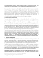
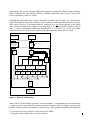
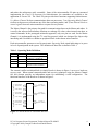
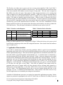
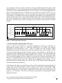
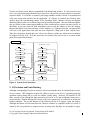
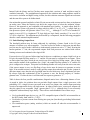
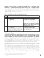
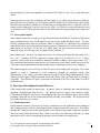
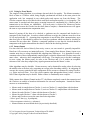
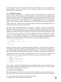
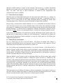
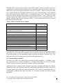
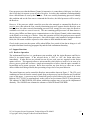
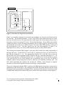
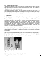
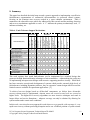
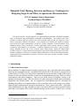
Minimalist Fault Masking, Detection and Recovery Techniques for
Mitigating Single Event Effects in Spaceborne Microcontrollers
UCLA Computer Science Department
Technical Report TR-980025
D. W. Caldwell* , D. A. Rennels*
University of California, Los Angeles, CA 90024
[email protected], [email protected]
Abstract
This paper presents a design approach for implementing fault-tolerant embedded computing
nodes in spacecraft using non-hardened, commodity microcontrollers. The approach uses faulttolerance to address high rate transient errors and occasional latch ups that are expected of such
devices in the space radiation environment. A key constraint is to minimize the amount of external
logic needed to support fault-tolerance so that the primary advantage of microcontrollers, high
functional density, can be maintained. Low-cost approaches which leverage features of existing
commercial microcontrollers are discussed. A built-in, high-speed serial port is used for voting
among redundant devices and a novel wire-OR output voting scheme exploits the bidirectional
controls of I/O pins. A fault-tolerant node architecture is presented, and the effectiveness of the faulttolerance techniques is discussed. A testbed is being constructed to verify the described techniques,
using triplicated microcontrollers to control a 3-axis set of rate gyros, thereby providing a realistic
application example.
1. Introduction
1.1 Microcontrollers in Space
Microcontrollers are highly integrated computer systems on a chip: a processor and various support
functions such as program memory, scratchpad RAM, discrete I/O, A/D converters, serial ports, and
counter/timers. [1,2] These very inexpensive commodity devices have not been widely used in space
because of their low radiation tolerance, in part due to manufacturing processes which use mixed
semiconductor fabrication techniques. There are two broad classes of problems caused by the
radiation environment in space. The first of these, the total ionizing dose which causes performance
degradation and ultimate failure, may be mitigated for non-hardened parts by screening and
shielding; this problem is not addressed herein. The second class is due to the passage of is a single,
highly-energetic charged particle through a semiconductor. These “single event effects” (SEE) have
many manifestations; the most common are single event upsets (SEU) which are transient bit-flips
and single event latchups (SEL) which stimulate parasitic circuits within a CMOS device causing
*
Both authors are also employed by the Jet Propulsion Laboratory, Pasadena, CA in the Avionics Systems and Technologies Division.
UCLA Computer Science Department Technical Report TR-980025
©Copyright 1998 by Douglas Caldwell and David Rennels
1
locally high, potentially destructive currents and which can only be cleared by power-cycling. Both
of these types of SEE can be expected to occur frequently in non-hardened devices in space. [3,4]
Two approaches can be taken to address SEE: using radiation hardened devices or using faulttolerance techniques. Rad-hard chips are difficult to develop and therefore costly; functional density
must be sacrificed to the design rules of SEE-immune layout. Also, because the fabrication
technologies required to implement the commercially-available on-chip functions such as EPROM
program memory and A/D converters are generally incompatible with rad-hard processes, such
functions are moved off-chip. Fault-tolerance techniques potentially allow a much wider choice of
higher performance devices, supported by a wider range of development tools, which evolve as
device families and thus incorporate the latest software development paradigms.
1.2 Fault-Tolerance Requirements
The search within the aerospace industry to dramatically reduce the cost of high-performance
spacecraft makes the use of non-hardened, commercial microcontrollers extremely attractive. As it
is not cost-effective to modify these devices, fault-tolerance is the only option available to mitigate
SEE susceptibility and make them usable. Other fault-tolerance requirements can viewed as an
economic tradeoff, as far as the use of microcontrollers is concerned. If the surrounding circuitry
becomes too complex, the design should probably be done with a microprocessor (building memory
and customized interface circuitry on the outside) because most of the high functional integration of
the microcontroller will be lost. The goal of this research is to provide as much fault-tolerance as
possible with available devices and few augmentations – thus the notion of “minimalist” indicated
by the title. This characteristic distinguishes this work from most previous research. [5]
The architecture presented handles transient SEE and many permanent faults. When viewed from a
spacecraft engineering perspective, the subsystem-embedded controller often has a lower permanent
failure rate than its host subsystem. If single points of failure represent a small part of the overall
failure rate, some can be accepted without significantly compromising the reliability of the
subsystem. Similarly, it is expected that some imperfections in coverage (the probability of
detection and correct recovery) can be handled by other on-board computers or ground intervention.
2. Physical Architecture
Available microcontrollers provide little internal error detection, necessitating some form of
replication – either duplex, triplex or hybrid for fault masking, detection and correction of errors.
Since these devices typically consume a small fraction of a watt but replace more voracious devices,
the overhead of multiple devices should be acceptable even in power-limited space missions.
The block diagram of a spacecraft functional element (e.g., an IMU) containing a fault-tolerant
group of microcontrollers (also interchangeably called “processors” hereafter) is shown in Figure 1.
At the top of the figure, the system to which the functional element is attached is shown as just a
source of power and communications. The I/O of multiple processors are combined and protected
by I/O isolation; the external conflict resolution circuit may reset or power-cycle the devices.
During normal operation, one microcontroller is the Master of the system, while the others provide
redundant computation and voting opinions as Checkers. The Master and Checkers are loosely
UCLA Computer Science Department Technical Report TR-980025
©Copyright 1998 by Douglas Caldwell and David Rennels
2
synchronized and execute identical application programs, periodically calling support functions
which implement the fault-tolerance features. During initialization and as part of some faultrecovery operations, a device is Offline.
Although the application code executes identically on Master and Checkers, the fault-tolerance
support functions are necessarily different, with the Master coordinating fault-tolerance among the
one or more Checkers. The Master might be considered to be the microcontroller of the system
while Checkers determine the validity of its computations. If a microcontroller disagrees with its
peers, it can be commanded Offline and brought back as a Checker if it can be successfully
restarted. Devices are not statically assigned so the operating mode of each device is fluid.
System
Communications
System Power
System Interface Boundary
Systems
Communications
Buffers & Other
Support Circuits
Node
Power
Control
to Other Loads
Fault Containment Region
Common
I/O
Isolation
Functions
µC
Power
Control
External
Conflict
Resolution
Vcc
RESET
Processor 1
I/O
Isolation
I/O
Isolation
Vcc
RESET
Processor 2
I/O
Isolation
I/O
Isolation
Vcc
RESET
Processor n
I/O
Isolation
I/O
Isolation
Check Channels
Normal I/O Channels
Common
I/O
Isolation
Functions
Node-Specific
MicrocontrollerManaged Functions
Figure 1. Physical Architecture.
Most of the I/O of the multiple processors is bussed together − corresponding pins are connected to
a common circuit node through isolation elements (resistors); only the signals governing the
external conflict resolution are unique to each processor. This approach simplifies interconnection
UCLA Computer Science Department Technical Report TR-980025
©Copyright 1998 by Douglas Caldwell and David Rennels
3
and makes the architecture easily extensible. Some of the microcontroller I/O pins are consumed
implementing the Check I/O necessary for fault-tolerance; the remainder are available to the
application as Normal I/O. The Check I/O pins provide three functions supporting fault-tolerance:
1) a Master Channel for data communications between processors, 2) an Operating Mode Channel
to allow each processor to broadcast one of the three operating modes, and 3) four External Resolver
control signals from each microcontroller to request recovery actions.
The Master Channel is the primary data path for communications between the Master and others. It
is used by the software fault-tolerance functions to exchange I/O values, other internal state data, or
control commands. In the prototyped minimalist approach, only two pins are used for the Master
Channel; it is implemented using the I2C serial bus protocol which was designed for chip-to-chip
interfacing and is available as a hardware peripheral block in the chosen microcontroller.
Each microcontroller generates a two-bit quasi-static Operating Mode signal indicating to its peers
its level of participation in the system. The definition of these bits is shown in Table 1.
Table 1. Operating Mode Definition.
MASTER
0
CHECKER
0
0
1
1
1
0
1
Indicated Status
Offline: off, resetting,
initializing, or standing-by.
Checker.
Master.
Intermediate metastable state
between Checker and Master.
The external conflict resolution block (or simply Resolver) shown in Figure 1 serves as a hard core
recovery unit. When normal communications and recovery techniques using the Master Channel
fail, this element provides an independent means for establishing a valid configuration. The
functional interface of the Resolver is shown in Figure 2.
{ Action Request,
Device Select }
4
{ Power ISOFF }
1
{ Action Request,
Device Select }
4
{ Power ISOFF }
1
{ Action Request,
Device Select }
4
{ Power ISOFF }
1
2
Processor 0
{ RESET, ON/OFF }
2
Processor 1
{ RESET, ON/OFF }
2
Processor 2
{ RESET, ON/OFF }
P0
Resolver
P1
P2
Figure 2. External Resolver Functional Interface.
UCLA Computer Science Department Technical Report TR-980025
©Copyright 1998 by Douglas Caldwell and David Rennels
4
The Resolver can either reset or power-cycle one or more microcontrollers. Table 2 and Table 3
enumerate the control signals available to each processor. The Action Request bits indicate the state
of the microcontroller and whether an action request is being made. The (0,0) state is assigned to
Idle Offline since this is the state of the outputs of either an unpowered chip or of a resetting chip
when its outputs are tri-stated but pulled-down externally. When active but not requesting that an
action be taken, the microcontroller indicates that it is Online but not making a recovery action
request. The other two patterns request restart actions. When an action is requested, the Device
Select bits specify the microcontroller(s) to be acted upon. An action request by a microcontroller
directed at itself is immediately taken, but action requests directed at other microcontrollers must be
concurred by a peer for the requested action to be taken. The “reset self” combination of Action
Request and Device Select is not required since this action can be taken by any device without the
aid of the Resolver. Thus, this input combination is redefined to mean “power-cycle all.”
Table 2. Resolver Action Requests.
RESET# CYCLE# Requested of State or Action
0
0
Idle Offline. Unpowered or not
voting. No action requested.
1
1
Idle Online. Expected to vote
but no action requested.
0
1
Vote to Initiate Resetting.
1
0
Vote to Initiate Power-Cycling.
Table 3. Resolver Device Selection.
DevSel1
0
0
1
1
DevSel0
0
1
0
1
Soft-SCP Usage
Self/All
N/A
N/A
All (Both)
TMR Usage
Self/All
Right
Left
Both Peers
Finally, the Microcontroller Power Control block of Figure 1 allows the devices to be power-cycled
by the Resolver and also provides some SEL mitigation functions. More details about the hardware
may be found in [6,7]
3. Application Characteristics
It is useful to examine the real-time processing paradigm which is typical for microcontroller
applications and which will be used in the inertial measurement unit serving as the test application
for the implemented prototype. Most microcontroller applications are structured around some realtime task which is executed frequently and periodically. [8] A “real-time frame” is initiated by a
real-time interrupt (RTI) and will have many sub-tasks. Figure 3 show an abstraction of a typical
real-time frame including the fault-tolerance processing which will be discussed herein. The user’s
application code runs in both foreground and background, the latter typically handling low-level
input tasks. In the prototypical application investigated, the R-T frame is 62.5 ms long, being
initiated by a 16 Hz interrupt. The background task samples three rate gyros at 10.8 kHz and does
so 220 times for each gyro in every frame. After data are gathered, some output results are
generated; these may be outputs which will drive physical devices, telemetry data returned to a
higher-level (system) application, or state data which will be used as the initial conditions of the
next R-T frame. (The data-gathering process may or may not continue during this time; in the
prototype, it is not − as indicated by the dashed lines.) Some amount of idle time exists in every
real-time application to accommodate processing-time uncertainties.
A number of fault-tolerance processes are required to support this application processing. Before
outputs are generated or propagated to the next R-T frame, they are checked for validity to prevent
UCLA Computer Science Department Technical Report TR-980025
©Copyright 1998 by Douglas Caldwell and David Rennels
5
error propagation. Data may also be checked at various user-defined intermediate points to limit
fault detection latency. The asynchronous detection of Single-Event Latchup (by external hardware)
will result in a device being automatically power-cycled. In Figure 3, this is shown happening to the
Master, which immediately results in a Master-less system and the consequent selection of a new
Master by the remaining processors. The loss of any processor, such as due to a peer-commanded
reset following a vote should not interrupt processing but is unavoidable in some pathological cases
which result in a system restart. (Power-cycling both the Master and a Checker during the same R-T
frame is for illustration only!) Finally, time at the end of the frame is reserved for communicating
state data to a previously reset or power-cycled processor to rejoin the voting ensemble as an online
member.
One Real-Time Frame
Application
Foreground
Tasks
Process User
Requests
Process User Requests
Check
Intermediate
Data
Fault
Tolerance
Generate
Frame
Result
Idle
Change
Outputs
Check
Output
Data
Check
State
Data
Offline
Processor
Rejoin
Application
Background
Tasks
Power-Cycle Master
Fault
Tolerance
Reset Checker
Reselect Master
= Sample Inputs
RTI
RTI
Figure 3. Real-Time Frame Structure.
4. Fault-Tolerance Functionality Overview
Figure 4 expresses system behavior in a statechart containing four primary state machines: one
representing the primary system as a whole and determined by very similar state machines
representing each microcontroller’s state. (There are another four state machines running
asynchronously with respect to the first set which select which processor will act as Master. These
are shown as single states in this figure and their operation is described later.) Initially OFF, the
system transitions to a RESET state as soon as any processor is powered. Processors automatically
transition from their individual PROCESSOR_RESET states to running code. Initialization codes
are executed which perform self-tests, configure I/O and start the processor fault-tolerance (PFT)
functions. The first PFT function is to select one of the processors as a Master. When at least two
processors are online and have agreed on a Master, the user application starts running. At userspecified locations in the application code, calls are made to PFT functions which implement the
fault-detection and recovery functions.
Fault-detection and isolation are primarily covered by software-implemented voting algorithms. In
voting events, the Master transmits a packet of data to each Checker which, being roughly
synchronized and thus at the same point in the application code, expects a check-packet. Each
Checker computes its own check-packet, compares the received packet with its own, and reports
equality (OK) or inequality. If no errors are detected, the processors are resynchronized and the
application continues.
UCLA Computer Science Department Technical Report TR-980025
©Copyright 1998 by Douglas Caldwell and David Rennels
6
If errors are found, correct data are transmitted to the disagreeing member. If a processor does not
receive an expected message (identified by a timeout), it can generate an action request to restart the
expected sender. If a Checker is restarted, processing continues and the Checker is resynchronized
at the next rejoin point specified by the application. If a Master is restarted, the Checkers must
quickly detect the corresponding change in the Operating Mode Channel, and have the highest
numbered Checker take over as Master to prevent processing disruption. One reason that the Master
may go Offline is that current-sensing hardware in the external power control can detect an SEL in
the Master at any time and will then immediately power-cycle the Master to clear the latchup.
Because the Master is the sole generator of some outputs (e.g., high-speed clocks), an output glitch
will occur if the application waits until the next cooperative voting point to deal with the error.
Thus, the system must identify this case, select a new Master, and the new Master must reconfigure
its outputs to fill the void. If all the processors are restarted, they must revert to a system restart
point in the application software.
SYSTEM
SYSTEM_STATE
PROCESSOR_n_STATE
OFF
PROCESSOR_OFF
RESET
Processor Fault: Recover by Reset
PROCESSOR_RESET
any processor leaves reset
INITIALIZATION
recovery impossible
PROCESSOR_INIT
Master selected
APPLICATION
FAULT_DETECTION
Master selected
PROCESSOR_APP
check_xxx()
PROCESSORS_VOTING
system
fault
no fault
FAULT_RECOVERY
Processor Fault: Recover by Power-Cycle
any processor on
system
fault
no fault
PROCESSOR_RECOVERY
recovered
RESYNCHRONIZATION
PROCESSOR_SYNCH
SYSTEM_MASTERSHIP
OPERATING_MODE
Processor OK, or
Processor Fault:
Recover by Coercion
Figure 4. System-Level Statechart.
5. I/O Isolation and Fault-Masking
Although corresponding I/O pins are bussed, each microcontroller must be isolated from its peers
for two reasons. SEL mitigation requires the ability to power-cycle devices; supporting non-stop
operation requires being able to cycle one without cycling others. However, the bussed I/O will
allow current to flow through the input protection devices of an I/O pin and thereby back-power a
microcontroller. Without limiting this current, logic-level outputs may be sufficient to sustain the
latchup condition. The second function of the isolation circuits is to support voting the outputs.
Although the Master will ascertain from the Checkers whether its computed results are correct, it
cannot be the sole generator of outputs because its output port flip-flops are susceptible to upset.
UCLA Computer Science Department Technical Report TR-980025
©Copyright 1998 by Douglas Caldwell and David Rennels
7
Instead, both the Master and its Checkers must output their versions of truth and these must be
combined externally. The straightforward approach to the isolation and voting problems would be
to use active isolation and digital voting circuits, but this solution consumes significant real-estate
and does not allow ports to be bidirectional.
One minimalist approach might be to limit I/O pin current with resistors and use these to implement
an analog voter, where the majority vote drives the output above or below the midpoint voltage.
However, this approach is not compatible with standard logic families. A single output fault in a
three-processor system will generate a voltage which is either 1/3 or 2/3 of VCC; a single fault in a
four-processor system will generate either 1/4 or 3/4 VCC. Although 2/3 or 3/4 of a standard 5V
supply (even at 4.5V) is a legitimate TTL logic high, no logic family considers 1/3 or even 1/4 of
VCC to be a legal low. The midpoint may be detected by a comparator, but the following paragraphs
describe a more minimal implementation.
5.1 Fault-Masking Output Ports
The threshold problem may be better addressed by exploiting a feature found in the I/O port
structure of almost every microcontroller. Two bits are used to define a single port pin and these
two bits may be used to make it difficult to inadvertently generate an active “1”; then, favoring the
hard-to-generate “1” bits, the so-generated outputs from each processor are isolated with currentlimiting resistors and combined with a logical OR.
For most devices, I/O pins are bidirectional and it takes two conditions to output a high level on an
I/O pin; the output flip-flop must be a “1” and the I/O pin must be configured as an output. There
are three other state pairs which do not result in an active high level being output. One of these
states satisfies neither of the conditions for a “high”: the output flip-flop contains a “0” and the I/O
pin is configured as an input. This point lies Hamming distance two away from the active-one state;
if the correct output is zero, two flip-flops of one device must be incorrect to generate an active
high. If an external resistor is used to weakly pull the output down when the pin is in the {output=0,
direction=input} state, then the only legal high state lies two faults away from a legitimate low state.
By always using this combination of bits to generate a zero, the desired property of “hard-togenerate ones” is achieved since it will then take two upsets to generate a “1”.
Table 4 shows the four possible combinations; diagonal entries have a Hamming distance of two.
As noted in italics, the solution does not preclude illegal outputs from a single processor; with
probability 0.25, a single bit error can result in an active low output; also, and the input protection
circuits of an unpowered device will sink current. In either of these cases, correct peer outputs will
drag the signal to an acceptable “high” (greater than 2/3 VCC) although this is not necessarily
compatible with an arbitrary logic family. These effects can be handled in one of three ways:
•
•
•
Use low-threshold input devices (e.g., the TTL-compatible inputs of the PIC microcontrollers or
the HCT family, both with VIH = 2.0 V);
Use diodes to prevent current from flowing into port pins (but thereby precluding bidirectional
operation);
Use transmission gates (analog switches) which are turned off when the microcontroller is
unpowered.
UCLA Computer Science Department Technical Report TR-980025
©Copyright 1998 by Douglas Caldwell and David Rennels
8
Essentially, the two register bits of the output port redundantly encode a single output, thereby
protecting it. If any of these protected outputs generates an active “one”, it determines the output
value for the wire-ORed ensemble. A side-effect of the active-high dominance is that the resulting
output will be high from the time that the first device outputs a high until the last device releases it.
A pulse widening equal to the maximum clock skew between any two processors occurs which is
significant for high-speed outputs such as clocks.
Table 4. I/O Pin States for SEU-Tolerance with Active One.
Output
Value
Tri-State Enable Bit (PIC Microcontroller Interpretation)
1 (Configure as Input)
Valid State: 0.
Output = hi-Z.
External pull-down yields a “zero.”
0
1
Invalid State.
Output = hi-Z.
Fault is either incorrect I/O configuration or
incorrect output bit; output is tri-state. Correct
state of the voted node will be forced by other
microcontrollers and the external pull-down.
0 (Configure as Output)
Invalid State.
Output = low-Z, logic-zero voltage.
If fault is incorrect I/O configuration state, low voltage
output matches desired state (helps the external pulldown).
If fault is incorrect output bit, a majority is
generating low-Z, logic-one voltage; a push-pull
conflict exists. “Voted” node state depends on logic
thresholds (high and low) of receiver.
Valid State: 1.
Output = low-Z, logic-one voltage.
Output overrides external pull-down.
(But an output-bit fault in another microcontroller
results in a push-pull conflict.)
5.2 Coverage Limitations
This masking technique relies on it being impossible for a single error in an output port to result in
an active-high fault, thus any active high is assumed to be correct. This only protects the output port
bits after an output has been generated; it does not prevent a processor from driving both output port
bits to a bad state (e.g., as the result of an incorrect computation). If the correct output value is a
zero but a single device decides to output a low-impedance “1”, that output will override any
number of high-impedance zeroes. This common-mode failure must be addressed by the softwareimplemented fault-tolerance functions which use the Master Channel. However, single-bit errors
occurring in the short window after software voting but before port output remain uncovered.
Latent faults in port registers can lead to double-bit errors and these static outputs are vulnerable
100% of operating time. Periodic scrubbing can be used to detect errors but the error rate can be
reduced only so far; scrubbing too frequently increases the probability of introducing a commonmode “double-bit error” (as noted previously) as a result of a single-bit error during the scrubbing
computation. The additional information about correctness required for scrubbing may be stored
redundantly in RAM or determined by reading the port bits directly. The latter approach requires
that the output and configuration bits be independently readable, a feature which is also valuable for
validation experiments to determine the likelihood of I/O port flip-flop upset. The PIC
UCLA Computer Science Department Technical Report TR-980025
©Copyright 1998 by Douglas Caldwell and David Rennels
9
microcontrollers [2] have this capability, as do the Intel 87C196Kx, Jx and CA [1]; many older parts
do not.
If the expected error rate after scrubbing is still too high (e.g., for safety-critical functions), hardware
interlocks may be used wherein a critical function must be enabled by an independent control signal.
Interlocks are particularly valuable in a self-checking pair configuration since a single-bit error will
always result in ambiguity if only two devices are voted. An I/O pin on each microcontroller used
as an interlock will result in the equivalent of four microcontrollers participating in the output state
vote.
5.3 Uncoverable Outputs
Some outputs cannot be covered by the previously-described mechanism. Consider a high-speed
output peripheral block, one which might be generate a pulse-width modulated signal. The nonlockstep synchronization between processors makes it impossible to synchronize the peripherals
better than the skew between instruction streams; because a single high level will override two lows,
high outputs are stretched. In the case of a PWM signal, the skew between processors directly
results an output error: the duty cycle is changed by the stretched “1”.
In the limiting case, the skew can change not only the waveform of the signal but may render it as a
D.C. level. Consider a 250 kHz square-wave output: high for 2 µs and low for 2 µs. A threeprocessor system of PIC microcontrollers running at 20 MHz (5 MIPS) with one processor (“only”)
five instructions faster than the mean and one five instructions slower than it would always have one
of the three clocks high and therefore the merged output would be perceived as never changing.
This shortcoming may be covered by an external circuit which implements a majority voter, either
digitally or using a comparator to detect transitions through the midpoint voltage (thus
implementing a true analog voter rather than the described self-checking/masking analog voter).
Alternatively, the signal could be generated only by the Master if the consequent lack of coverage is
acceptable. This solution also places a premium on detection of the loss of the Master as will be
described below.
6. Detection, Reconfiguration and Recovery
Fault masking only applies to output ports. In general, faults are identified and corrected through
detection, reconfiguration and recovery. The detection process begins with software voting.
Following fault diagnosis, the system is reconfigured if necessary by taking the faulty device offline
(isolating it from the rest of the system) and possibly selecting a new Master. The system recovers
by forcing errant devices to restart.
6.1 Normal Operation
During normal operation, processors are loosely synchronized so the application code running on
each voting processor reaches a checkpoint function at approximately the same time. The Master
manages the voting process by first passing data to the Checkers and getting responses from them.
The most benign faults detected are those which occur only in the data being checked (e.g., input
data) and recovery can be accomplished by passing corrected values to each processor.
UCLA Computer Science Department Technical Report TR-980025
©Copyright 1998 by Douglas Caldwell and David Rennels
10
6.1.1 Voting by Exact Match
The simplest voting algorithm is to exchange data and check for equality. The Master transmits a
block of data to a Checker which, being roughly synchronized and thus at the same point in the
application code, has computed its own check-packet and expects one from the Master. The
Checker compares the received block with its own block and reports equality (OK) or inequality. The
return status is encoded such that upsets occurring between its computation by a Checker and its
transmission to the Master are identifiable. (No such parity is required for Master-to-Checker
transmissions because the Checker has the check data to compare; a transmission error will appear
the same as a pre-transmission computation error.)
Instead of passing all the data to be checked, a syndrome may be computed and checked as a
surrogate for the actual data. In order to obtain sufficient coverage, the syndrome must be at least
16 bits and preferably 32. Assuming that computation is much faster than communication, more
than four bytes of data should be reduced to a four-byte syndrome which may then be checked for
exactness like any other data. Whether a computed syndrome or raw data are checked should be
transparent to the application and thus the choice is buried in the checking function.
6.1.2 Inexact Inputs
For data which are derived directly from noisy sources, an exact match is generally impossible.
Data from A/D converters are intrinsically noisy. Data sampled from discrete (binary) inputs even
contains noise due to voltage threshold and sampling-time differences. It is important to reach a
consistent value of these independently-sampled inputs, so that the Master and Checkers can use the
same values – otherwise, their computations will diverge. The simplest way to do this is analogous
to exact voting: the Master passes its value to the Checkers and, if it is within an acceptable
tolerance of the value they sampled, they signal agreement and use the Master’s value.
Other algorithms may be desirable. Greater accuracy can be obtained for analog values by selecting
the middle value as the best or by computing an average (after discarding outliers). In computing an
average, the accuracy gained also helps compensate for the resources consumed by using Checkers,
e.g., power and real-estate. For a byte which contains eight independent binary values, a bitwise
best-of-three algorithm may be desired. Either of these is considerably more complex.
With a master-slave Master Channel such as I2C, the Master completely controls the transaction and
the Checkers are unable to broadcast information for universal consumption. Instead the Master
must act as an intermediary:
• Master sends its sample data to Checker 1; receives Checker 1’s sampled data with checksum.
• Master sends its sample data to Checker 2; receives Checker 2’s sampled data with checksum.
• Master forwards Checker 2’s data with checksum to Checker 1.
• Master forwards Checker 1’s data with checksum to Checker 2.
• Master and Checkers execute the same data fusion algorithm:
- Select “good” data (e.g., by midpoint);
- Select acceptance criteria (e.g., tolerance);
• Master initiates an exact-match check (as previously described).
UCLA Computer Science Department Technical Report TR-980025
©Copyright 1998 by Douglas Caldwell and David Rennels
11
As only random SEU errors are addressed and these are not malicious, the use of a checksum (or
other appropriate code) on the Checkers’ data is sufficient to identify errors introduced by the
Master in its role as a data router.
6.1.3 “Meta-Measurements”
In microcontroller applications, it is common to perform some processing on a possibly large
number of samples. For example, the reported angular rate of a gyro may be the normalized average
of many rate measurements. In the testbed application, three gyros are sampled at 10.8 kHz and 220
sample values from each gyro are aggregated to form a reported angular rate; the rate is reported to
the host system 16 times a second. In this case, it is completely impractical to vote each individual
sample − but it is also unnecessary; an aggregated value is essentially a single measurement from an
abstract input device. Since the values are simply summed and averaged, the resulting averages can
be dealt with by inexact voting as described above.
The many simple measurements may be combined by summing a sequence (accumulation),
determining maximum and minimum values, or counting occurrences for statistical purposes (e.g.,
“binning”). A strong constraint on such processing is that conditional branches must not be made
which result in non-local control flow changes; such changes can result in divergent behavior which
causes the voting microcontrollers to reach their checkpoints outside their allocated time windows
or, worse, to reach different checkpoints. The constraint may require addressing processing
subtleties to ensure that timing variations do not occur due to local conditional branches such as in
the following code which counts the occurrences of low, medium and high sample values:
if (sample < threshold_low)
++ bin[0];
else if (sample > threshold_high)
++ bin[2];
else
++ bin[1];
Although a “natural” solution, it has undesirable timing uncertainty. A signal which lies right on the
low threshold will sometimes take the shortest path through the code and sometimes the longest. If
two microcontrollers have slightly different A/D voltage references, one device could consistently
take the shorter path while the other takes the longer. Over many such samples, the difference in
execution time could result in a loss of synchronization. This can be written (less naturally and
statistically slower, but clearer) such that the code always executes in exactly the same time:
if (sample <
++ bin[0];
if (sample >
sample <
++ bin[1];
if (sample >
++ bin[2];
threshold_low)
threshold_low &&
threshold_high)
threshold_high)
Even “simple” constructs like multiplication may be problematic since compiler-emitted code may
include complex conditionals rather than treating all operands identically (e.g., to speed-up trivial
operations like multiplication by zero or one).
6.1.4 Placement of Checkpoints
The simplest approach of voting after every input may be prohibitively expensive and unnecessary.
Data which will be output to ports, intermediate results which can lead to control-flow divergence,
UCLA Computer Science Department Technical Report TR-980025
©Copyright 1998 by Douglas Caldwell and David Rennels
12
and state variables which are “output” by one iteration of processing (e.g., a periodic calculation)
and then used as input to the next iteration must all be voted. It is probably wise to simply “vote
early, vote often” with only as much moderation as dictated by the computational and
communication resources available.
6.2 Control Errors in Checkers
Data-only upsets are fairly benign but an upset can cause a processor control error, e.g., causing it to
jump erroneously or get locked up looping on completely invalid data. A significant effect on a
Checker is for it to not reach its next voting checkpoint thereby precluding the Master from
exchanging data with it. Timeouts are used by the Master to diagnose this condition.
During voting, communications timeout durations are set to accommodate the maximum expected
clock skew between processors and any additional delay which results from application interrupt
processing (e.g., handling real-time tasks) and from differences between Master and Checker faulttolerance functions. If a Checker fails to communicate within the allocated time, either the Checker
has failed or neither Checker was expecting the Master, in which case the latter is probably in error.
In the former case, the Master can communicate with the functioning Checker and the data to be
checked can be at least tested for validity (as a self-checking pair). Additionally, the Master will
request that the functioning Checker participate in voting the failed Checker to the Offline state
using the External Resolver.
6.3 Control Errors in the Master
Just as a Checker may get lost, so may the Master. The process for dealing with a Master is
necessarily quite different because the cooperative process of asking for help cannot be effected
without the control of the Master; the Checkers are on their own.
Just as the Master sets communication timeouts, so too do the Checkers. If the Master fails to
contact a Checker and the Checker believes itself to be healthy, it must conclude that the Master is
in error. Without waiting for some confirmation of this fault, it signals to the Resolver its desire to
reset the Master. If the other Checker observes the same phenomenon, it will also have voted for an
external reset and the Resolver will reset the Master.
When the Master is reset or power-cycled, its Operating Mode bits will go tri-state and be pulled
down to (0, 0). This transition indicates a Master-less system and must be identified by the
Checkers; if any outputs are generated solely by the Master (as already described), loss of the Master
must immediately be followed by the selection of a new Master and its outputs properly configured.
An interrupt may be generated externally by the all-zeroes case on the Master Operating Mode
signals. Microcontrollers which can generate interrupts on input port pin changes do not need such
external hardware; the PIC16C73 can flag a change on any of the high-order four bits of port B with
an interrupt.
When the system loses its Master, the change is detected immediately if an interrupt is used (as is
necessary if there are Master-only outputs) or when the next data checking operation occurs. In both
of these cases and when the system is first started, a Master must be selected.
UCLA Computer Science Department Technical Report TR-980025
©Copyright 1998 by Douglas Caldwell and David Rennels
13
When the Master Selection process starts, it first checks whether a Master is present; no action is
required if one is already present and the processor is already the Master or a Checker. If there is no
Master and no Checkers, the processor declares itself to be a Checker. If there is at least one online
peer, voting is possible and any Master-capable processor may claim Mastership. A race condition
exists here between Master-capable devices so an additional step reverts to Checkers those peers
with lower priority than that of the highest priority Master-claimant. Once a Master has been
selected, it queries any Offline members to see if they are ready to join (or rejoin) the ensemble. An
example timeline of this process is shown in Table 5. It also includes the case where a restarted
checker is brought back on-line.
Table 5. Master Selection Process Timeline.
Conditions or Event
Initial condition after system reset.
A Master-capable processor reaches Master Selection.
Second processor reaches Master Selection, but is not capable
of Mastership so it does not claim to be.
P1 observes 2-Checker state and claims Mastership.
P0 observes same condition and simultaneously claims Mastership.
P1 observes higher-priority Master (P0) and relinquishes.
--- Arbitrary time passes. System operates nominally. --P1 is taken offline; system is unaffected.
--- P1 reset occurs; one real-time frame passes --Master loads state into P1, requests that it rejoin as Checker.
--- Arbitrary time passes. System operates nominally. --P0, the Master, taken offline; system has no Master.
P1, a Master-capable Checker, observes the Master-less system,
claims Mastership, and reconfigures its outputs as Master.
--- P0 reset occurs; one real-time frame passes --Master loads state into P0, requests that it rejoin as Checker.
Proc. Operating Mode
P0
P1
P2
O
O
O
O
C
O
O
C
C
M
M
C
M
C
C
M
O
C
M
C
C
O
O
C
M
C
C
C
M
C
Note that when a Master goes offline, the system may not operate non-stop; the Mastership selection
process takes a few microseconds and glitches may be observed on Master-only high-speed outputs
as the responsibility for their generation changes from the old Master to the new one. Any
deleterious effects of this outage must be dealt with at the application level.
6.4 Corrupted Master Channel
The most severe fault is one which renders the Master Channel inoperative. A “babbling” device
may cause this but the simplest mechanism is a Checker which simply sets one of its Master
Channel I/O lines to an active state thereby creating a conflict for the channel.
Although the Master Channel could be designed to preclude (with high probability) that Checkers
cannot take it down, the complexity required to both preclude bad behavior but allow all devices to
be Master-capable will violate any notion of minimality. Thus, it must be assumed that there is a
non-negligible probability that either the Master or a Checker can make the Master Channel
inoperative.
UCLA Computer Science Department Technical Report TR-980025
©Copyright 1998 by Douglas Caldwell and David Rennels
14
If any processor sees that the Master Channel is inoperative, it cannot know which peer is at fault so
after a self-check it requests a reset of both of its peers. In reality, this condition is indistinguishable
from a failed Master as seen by the Checkers. If the two correctly-functioning processors identify
this condition and are the first ones to command the Resolver, the failed processor will be reset by
the Resolver.
However, if the processor which caused the error has also managed to command the Resolver to
reset its peers, then when the first correctly-functioning processor requests that the Resolver reset
both its peers, the other correctly-functioning processor will wrongly be reset (since the Resolver
would have received two votes to reset it). The one remaining good processor will then observe a
device going Offline and then expect communication over the Master Channel, either transmitting
as the Master or receiving as a Checker. Since this operation will fail, the good processor requests
that the Resolver restart all three processors. Since this design is only intended to mitigate transient
faults, the full restart would be expected to clear whatever fault initiated the entire chain.
Clearly in this worst case the system will be taken Offline for a period of time but in doing so it will
not permit bad data from being propagated beyond the fault-containment boundary.
6.5 Support Functions
6.5.1 Resolver Operation
The implemented Resolver is a synchronous state machine, with the Action Requests and Device
Select as its control inputs. If the selected device is “Self” or “All”, the action takes place
immediately. If other devices are selected but not all, two such votes are required to take action
against a device. This approach allows a microcontroller which believes itself to be in error to be
reset or power-cycled and it allows a single microcontroller to believe that the entire ensemble is
beyond help and to restart everyone. But it does not allow any lone device to affect one or more
others without itself being affected, thus preventing a large class of wayward behavior.
The control inputs are used to control the Resolver state machine shown in Figure 5. The [GO_xxx]
conditions are derived from the control signals from each processor, but the formulae are beyond the
scope of this paper. A processor may be turned off (power-cycled) either as the result of an Action
Request (GO_CYCLE) or asynchronously as the result of an overcurrent (IFAULT) being detected.
The substates of PROCESSOR_OFF shown with broken outlines may or may not be implemented
distinctly. The ONLINE state contains the substates of MASTER and CHECKER.
UCLA Computer Science Department Technical Report TR-980025
©Copyright 1998 by Douglas Caldwell and David Rennels
15
RESOLVER
PROCESSOR ON
PROCESSOR OFF
RUNNING
OFFLINE
[GO_ONLINE]
[GO_OFFLINE]
ONLINE
[IFAULT]
[ G O _ CYCLE]
[GO_RESET]
RESETTING
[not GO_RESET]
CYCLING
FAULTED
[not GO_CYCLE]
[ISOFF]
[not GO_CYCLE and ISOFF]
Figure 5. Statechart for Single-Processor Restart.
Figure 5 is principally comprised of two smaller state machines, one for power on/off state and one
for reset state. The External Resolution - Power Cycling (ERP) state machine has only two states,
Processor On and Processor Off, represented by a single register bit which controls the processor’s
local power switch (a totem-pole FET pair). The External Resolution - Reset (ERR) state machine
similarly has only two states, Resetting and Running, with its single output bit tied directly to the
microcontroller’s reset pin. As is evident in Figure 5, the state of the ERR machine is irrelevant if
the microcontroller is off. The three copies (one for each microcontroller) of Figure 5 are
implemented in two PALs, one for three ERP machines and one for three ERR machines.
The resetting state machine (ERR) outputs a reset pulse which satisfies the timing requirements of
the target processor. For the PIC16C73 and 74, this is a minimum of 100 ns; for the PIC16C73A
and 74A, the minimum is 1 µs. The implemented Resolver has a 500 kHz clock so that the
RESETTING state can be implemented with a single bit and have a minimum duration of 2 µs. The
Resolver must guarantee a minimum duration since it is possible for a microcontroller to powercycle itself but then for its Action Request bits to immediately drop to the [not GO_RESET]
condition without actually being power-cycled or otherwise in an internally consistent state. The
PLD which implements this machine also decodes the “Offline” Action Request to suppress
operation of circuits which depend on the processor being a voting participant.
The power-cycling state machine (ERP) is similar to the ERR machine except that it awaits positive
confirmation of the desired effect. By watching for the ISOFF flag which indicates that the current
flowing into the microcontroller has dropped below a hardware-set threshold, a closed-loop control
is implemented which obviates the need for precise control of the state machine’s clock frequency.
UCLA Computer Science Department Technical Report TR-980025
©Copyright 1998 by Douglas Caldwell and David Rennels
16
6.5.2 Rejoining the Voting System
The application code must provide adequate time (e.g., during the time at the end of a real-time
frame which is otherwise idle) to allow restarted processors to rejoin the system. This is signaled by
calling the atomic function:
pft_rejoin( void *state, int state_bytes )
which initiates the rejoining operation. The Master checks the Operating Mode state of each of its
peers and attempts communication via the Master Channel with any Offline member. If the member
has initialized, it indicates its readiness to rejoin. The Master then rolls the new member forward by
transmitting all relevant state data, indicated by the function parameters.
7. Experiments
In order to produce an outcome which will be valuable to the spacecraft avionics community and to
provide a testbed for evaluating the effectiveness of the techniques, a prototypical application is
being built which is representative of a typical space system element, specifically a 3-axis inertial
measurement unit (IMU). This application is sufficiently complex to provide insights into real
problems while sufficiently simple that its implementation should not distract from the
investigation. The supporting testbed will accommodate two or three microcontrollers to implement
fault-tolerance and thus provide examples of different processor configurations. The example
forces many I/O requirements to be addressed, including bi-level and analog voting, pulse train
generation, event timing, and serial communications.
The testbed and IMU application use the Microchip PIC16C73A [2]. Its functionality, while
relatively limited, is sufficient to implement the chosen applications but these same limitations force
a frugal approach to fault-tolerance − it would be very easy to use all the I/O pins just implementing
fault-tolerance.
Some key aspects of the testbed environment which have been breadboarded are shown in Figure 6.
In the middle is a single-axis rate gyro with its interface electronics on the left. On the right is the
breadboard of a self-checking pair with two PIC16Cxx emulators plugged into it. A full TMR
breadboard controlling three gyros will be built in January 1998.
Figure 6. Testbed Breadboard.
UCLA Computer Science Department Technical Report TR-980025
©Copyright 1998 by Douglas Caldwell and David Rennels
17
8. Summary
This paper has described the initial steps toward a generic approach to implementing cost-effective
fault-tolerance augmentations of commercial microcontrollers in spacecraft control systems,
focusing on the transient error recovery needed in a space radiation environment. Table 6
summarizes the observable errors which are addressed by this research and the masking, detection
and recovery mechanisms applicable to each. A “1” indicates the primary mechanism(s) used, “2”
indicates secondary, etc.
Table 6. Fault-Tolerance Support Mechanisms.
Single-Event Upset Effects
data-only error in Checker
data-only error in Master
apparent “significant” error in Checker
apparent “significant” error in Master
incommunicative Checker
incommunicative Master
inoperative Master Channel
control flow error
hardware configuration error
data error in output ports
2
2
3
1
Power Cycle
Reset
Reconfiguration
Jamming Data
None
External Monitoring of
Supply Current
Watchdog Timer
Software-Implemented
Health Checks
Software Monitoring of
Voting Process
Fault-Recovery
Mechanism
1
1
1
1
1
1
1
1
1
1
1
1
1
X
2
X
1
X
1
3
2
1
1
2
Single-Event Latchup Effects
widespread loss of functionality
locally high currents
Secondary Effects
Checker forced offline
Master forced offline
Software Voting
Fault-Detection
Mechanism
Status Channel
Automatic Rewrite of
Discrete Outputs
Hardware Voting of
Discrete Outputs
Observed Effect (Error)
Inexact Match during
Voting Process
Fault-Masking
Mechanism
1
1
1
1
1
2
2
1
1
This work explores how much fault-tolerance can be implemented in a minimal design that
preserves the high functional density advantages of microcontrollers – without taking the costly step
of implementing microprocessor designs with extensive supporting interface circuitry. While there
has been extensive research and development of systems which provide extremely high levels of
fault-tolerance, including Byzantine resilience, they are expensive custom designs which exceed the
limited resources available for spaceborne applications. [5]
To achieve low-cost designs based on off-the-shelf components, we believe that a hierarchic
recovery scheme must be implemented, wherein errors not covered at one level are covered at
higher levels. The higher-level recovery algorithms use more invasive techniques and result in
longer delays and service disruptions − adequate coverage can only be obtained by allowing for
system restarts under certain error conditions.
In this work, a two-tiered recovery approach is used where we try to provide, with coverage c1, very
rapid error recovery without processing disruption and to use a fallback position of system restarts
UCLA Computer Science Department Technical Report TR-980025
©Copyright 1998 by Douglas Caldwell and David Rennels
18
for the remaining cases, with coverage c2. A c1 coverage above 95% appears reasonable with an
even higher value achievable for c2. In a typical space mission where a non-hardened
microcontroller might be expected to upset as often as once a day, such a coverage would mean that
the ensemble of processors would have a high probability of continuously operating for the life of a
mission although it would experience short processing disruptions every few months.
The
described experimental design is expected to provide us with the facility to perform experiments and
thereby gain the insights necessary to determine the effectiveness of these techniques.
9. Acknowledgments
This work was sponsored by the Office of Naval Research, under grant #N00014-96-1-0837 at the
University of California, Los Angeles.
10. References
[1]
“8XC196Kx, 8XC196Jx, 87C196CA Microcontroller Family User’s Manual.” Intel
Corporation, June 1995.
[2]
“PIC16/17 Microcontroller Data Book.” Microchip Technology, Inc. 1995/1996.
[3]
A. Holmes-Siedle, L. Adams.
Publications, Oxford, 1993.
[4]
G. C. Messenger, M. S. Ash. “The Effects of Radiation on Electronic Systems.” Second
Edition. Van Nostrand Reinhold, New York, 1992.
[5]
R. E. Harper, J. H. Lala, J. J. Deyst. Fault Tolerant Parallel Processors Overview. FTCS-18,
pp. 252-257. 1988.
[6]
D. W. Caldwell, D. A. Rennels. “A Minimimalist Hardware Architecture for Using
Commercial Microcontrollers in Space.” 16th Digital Avionics Systems Conference, Irvine,
CA. 28-30 Oct 1997.
[7]
D. A. Rennels, D. W. Caldwell, R. Hwang, M. Mesarina. “A Fault-Tolerant Embedded
Microcontroller Testbed.” 1997 Pacific Rim Fault-Tolerance Conference, Taipei, Taiwan.
15-16 Dec 1997.
[8]
H. Kopetz, et al. Distributed Fault-Tolerant Real-Time Systems: The MARS Approach. IEEE
Micro, February 1989.
[9]
S. G. Frison, J. H. Wensley. Interactive Consistency and Its Impact on TMR Systems in Dig.
Int. Symp. Fault Tolerant Computing, FTCS-12, June 1982, pp. 228-233.
“Handbook of Radiation Effects.”
UCLA Computer Science Department Technical Report TR-980025
©Copyright 1998 by Douglas Caldwell and David Rennels
Oxford Science
19