1
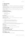
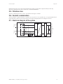
INGECON SUN 1Play TL M
Installation and usage manual
ABE2011IQE01_A
09/2014
Ingeteam Power Technology, S.A. - Energy
Avda. Ciudad de la Innovación, 13
31621 SARRIGUREN (Navarra) - Spain
Tel.: +34 948 28 80 00
Fax.: +34 948 28 80 01
e-mail: [email protected]
Service Call Center: +34 948 698 715
Ingeteam
INGECON SUN 1Play TL M
Installation and usage manual
ABE2011IQE01_A - Installation and usage manual
iii
Ingeteam
The copy, distribution or use of this document or of its content requires written authorisation. Any breach thereof will be reported for
damages. All rights reserved including those of patent rights or design registration.
The conformity of the document content with the hardware described has been checked. However, discrepancies may exist. Liability
will not be assumed for total concordance. The information contained in this document is regularly reviewed and it is possible that
there may be changes in subsequent editions. Other functions may be available which are not covered by this document.
This document may be changed.
iv
ABE2011IQE01_A - Installation and usage manual
Contents
Ingeteam
Contents
Contents ......................................................................................................................................................5
1. About this manual.....................................................................................................................................7
1.1. Scope and nomenclature...................................................................................................................7
1.2. Recipients........................................................................................................................................7
1.3. Symbols...........................................................................................................................................7
2. Unit description........................................................................................................................................8
2.1. Overview..........................................................................................................................................8
2.2. Optional accessories.........................................................................................................................8
2.3. Electrical safety................................................................................................................................8
2.3.1. Overvoltage category (OVC)........................................................................................................8
2.4. Protection rating...............................................................................................................................8
2.5. Pollution class..................................................................................................................................9
2.6. Acoustic contamination.....................................................................................................................9
2.7. Electrical diagram of the system.........................................................................................................9
2.8. Tables of specifications...................................................................................................................10
2.9. Residual current device...................................................................................................................12
2.10. Description of access....................................................................................................................12
3. Safety....................................................................................................................................................13
3.1. Safety conditions............................................................................................................................13
3.2. Personal Protective Equipment (PPE)...............................................................................................14
4. Receipt of the unit and storage.................................................................................................................15
4.1. Reception......................................................................................................................................15
4.2. Equipment identification.................................................................................................................15
4.3. Transport damage...........................................................................................................................15
4.4. Storage..........................................................................................................................................15
4.5. Conservation..................................................................................................................................15
5. Equipment transport...............................................................................................................................16
5.1. Transport........................................................................................................................................16
5.2. Unpacking.....................................................................................................................................16
6. Preparation for installing the unit.............................................................................................................17
6.1. Environment...................................................................................................................................17
6.2. Environmental conditions................................................................................................................18
6.3. Supporting Surface and Fastening....................................................................................................18
6.4. Protection of the connection to the electric grid.................................................................................18
6.5. Cabling length................................................................................................................................19
7. Installing the unit...................................................................................................................................20
7.1. General requirements for installation................................................................................................20
7.2. Attaching the unit to the wall...........................................................................................................20
7.3. Opening the housing.......................................................................................................................22
8. Connection of accessories........................................................................................................................23
8.1. Safety instructions for connecting accessories...................................................................................23
8.2. Opening precut holes and installing packing glands...........................................................................23
8.3. Wiring process................................................................................................................................24
8.4. Connecting the potential-free auxiliary relay......................................................................................24
9. AC connection........................................................................................................................................26
9.1. Safety instructions for the AC connection..........................................................................................26
9.2. Wiring requirements for connecting AC connection.............................................................................26
9.3. AC connection process....................................................................................................................26
10. DC connection......................................................................................................................................28
10.1. Safety instructions for the DC connection........................................................................................28
10.2. Wiring requirements for connecting DC connection...........................................................................28
10.3. DC connection process..................................................................................................................28
11. Commissioning.....................................................................................................................................30
11.1. Equipment inspection...................................................................................................................30
ABE2011IQE01_A - Installation and usage manual
5
Ingeteam
Contents
11.1.1. Inspection............................................................................................................................30
11.1.2. Hermetic sealing of the unit..................................................................................................30
11.2. Start-up.......................................................................................................................................30
12. Display control......................................................................................................................................31
12.1. Keypad and LEDs.........................................................................................................................31
12.2. Display........................................................................................................................................32
12.3. Menu structure.............................................................................................................................33
12.4. Daily power graph.........................................................................................................................34
12.5. Energy graph for the last 24 days...................................................................................................34
12.6. Main menu...................................................................................................................................34
12.6.1. Monitoring...........................................................................................................................35
12.6.2. Events.................................................................................................................................35
12.6.3. Start/Stop............................................................................................................................36
12.6.4. Settings...............................................................................................................................36
12.6.5. Advanced settings.................................................................................................................36
12.6.6. Inverter data........................................................................................................................36
13. Firmware update...................................................................................................................................37
13.1. Update process.............................................................................................................................37
14. Communication via USB........................................................................................................................38
14.1. Wiring process..............................................................................................................................38
15. Shutting down the unit..........................................................................................................................39
15.1. Process of shutting down the unit...................................................................................................39
16. Preventive maintenance.........................................................................................................................40
16.1. Safety conditions..........................................................................................................................40
16.2. Condition of the housing................................................................................................................40
16.3. Condition of cables and terminals...................................................................................................40
16.4. Cooling system.............................................................................................................................40
16.5. Environment.................................................................................................................................40
17. Troubleshooting....................................................................................................................................41
17.1. Alarms. LED messages..................................................................................................................41
18. Waste handling.....................................................................................................................................44
6
ABE2011IQE01_A - Installation and usage manual
About this manual
Ingeteam
1. About this manual
This manual describes the INGECON SUN 1Play TL M units and provides information for their correct reception,
installation, start-up, maintenance and operation.
1.1. Scope and nomenclature
This manual is applicable to the following units:
Complete name
Abbreviation
INGECON SUN 1Play 2.5TL M
2.5TL M
INGECON SUN 1Play 2.7TL M
2.7TL M
INGECON SUN 1Play 3TL M
3TL M
INGECON SUN 1Play 3.3TL M
3.3TL M
INGECON SUN 1Play 3.68TL M
3.68TL M
INGECON SUN 1Play 4.6TL M
4.6TL M
INGECON SUN 1Play 5TL M
INGECON SUN 1Play 5.5TL M
INGECON SUN 1Play 6TL M
5TL M
5.5TL M
6TL M
This document will refer to the various models by both their complete name and their abbreviation. Similarly, it will
refer generically to any of the models in the INGECON SUN 1Play TL M families with the terms unit or inverter.
1.2. Recipients
This document is intended for qualified personnel.
The status of qualified personnel referred to in this manual will be, as a minimum, that which meets all the
standards, regulations and laws regarding safety applicable to the tasks of installing and operating this unit.
The responsibility for designating qualified personnel will always fall to the company to which the personnel
belong. It is necessary to decide which workers are suitable or not for carrying out specific work to preserve their
safety at the same time as complying with occupational safety legislation.
These companies are responsible for providing appropriate training in electrical equipment to their personnel and
for familiarising them with the contents of this manual.
1.3. Symbols
This manual uses various symbols to emphasise and highlight certain texts. The general meanings are explained
below.
General warning.
General information.
Electrical danger.
Read the section indicated in this manual.
Hot surface.
Prohibition.
ABE2011IQE01_A - Installation and usage manual
7
Unit description
Ingeteam
2. Unit description
2.1. Overview
The basic purpose of an inverter is to convert the direct current generated by the PV array into alternating current
to feed into the electricity grid.
The INGECON SUN 1Play TL M are single-phase PV inverters with two maximum power point trackers (MPPT)
and a wide range of input voltages, which provides more alternatives when configuring the PV array and makes
asymmetric configuration possible.
They have been configured with a high performance topology that makes them highly efficient, eliminating stray
currents from the PV array.
As standard the inverter includes communication via USB, an SD card reader for updating the firmware and
potential-free relay for signalling.
2.2. Optional accessories
These units may include the following accessories:
•
DC isolating switch.
•
Communications accessories.
•
Digital input card.
•
Self-consumption kit.
DC isolating switch
These units may incorporate a direct current isolating switch.
Communications accessories
As standard these units have local communication via USB. In addition there is the option of establishing
connections using other technology types:
•
RS-485.
•
Ethernet (including communication via RS-485, for optional use)
•
Ethernet TCP (including communication via RS-485, for optional use)
•
GSM/GPRS (including communication via RS-485, for optional use)
•
Bluetooth.
•
Bluetooth (including communication via RS-485, for optional use)
The instructions for installing the communication accessories are indicated throughout this manual. For more
information on their functioning, consult the corresponding communication accessories manual.
Digital input cards
In certain countries this card is necessary to comply with their regulations.
Self-consumption kit
These inverters are compatible with all the self-consumption options offered by Ingeteam.
2.3. Electrical safety
The design values the electrical safety can be found below.
2.3.1. Overvoltage category (OVC)
The design of the unit complies with the regulations IEC 62109-1 and IEC 62109-2. The direct current circuits
have been designed with an overvoltage category II (OVC II), and the alternating current circuits with an overvoltage
category III (OVC III).
2.4. Protection rating
These units meet IP65 protection rating against external agents.
8
ABE2011IQE01_A - Installation and usage manual
Unit description
Ingeteam
IP65 means that the unit is fully protected against the ingress of dust and also against water jets from any
direction as defined for this level of protection in standard IEC 60529.
2.5. Pollution class
The units comply with pollution class 2, as required for this type of inverter.
2.6. Acoustic contamination
The unit produces a slight buzz when in operation. Do not place it in an occupied room, or on light supports which
might amplify this buzz. The mounting surface must be firm and appropriate for the weight of the unit.
PV input
Filter
PV input
MPP1
MPP2
AC output for connection to the
grid
2.7. Electrical diagram of the system
Optional
ABE2011IQE01_A - Installation and usage manual
9
Unit description
Ingeteam
2.8. Tables of specifications
2.5TL M
2.7TL M
3TL M
3.3TL M
3.68TL M
2.8 ~ 3.3 kWp
3 ~ 3.6 kWp
3.2 ~ 4 kWp
3.8 ~ 4.3 kWp
3.9 ~ 4.8 kWp
850 V
850 V
850 V
850 V
850 V
125 ~ 750 V
125 ~ 750 V
125 ~ 750 V
125 ~ 750 V
125 ~ 750 V
DC input
Recommended power range of PV array (1)
Maximum input voltage (2)
Voltage range MPP1 (3)
Voltage range MPP2 (3) (4)
90 ~ 750 V
90 ~ 750 V
90 ~ 750 V
90 ~ 750 V
90 ~ 750 V
Operating voltage range (4)
90/125 ~ 850 V
90/125 ~ 850 V
90/125 ~ 850 V
90/125 ~ 850 V
90/125 ~ 850 V
125 V
127 V
141 V
155 V
172 V
13 / 13 A
13 / 13 A
13 / 13 A
13 / 13 A
13 / 13 A
0 A rms
0 A rms
0 A rms
0 A rms
0 A rms
MPPT
2
2
2
2
2
Number of strings
2
2
2
2
2
Strings per MPP
1
1
1
1
1
11 / 11 A
11 / 11 A
11 / 11 A
11 / 11 A
11 / 11 A
11 A
11 A
11 A
11 A
11 A
Nominal power (up to 45 ºC)
2.5 kW
2.7 kW
3 kW
3.3 kW
3.68 kW
Maximum continuous power
2.5 kW
2.7 kW
3 kW
3.3 kW
3.68 kW
Max. temperature for nominal power (5)
60 ºC
57 ºC
55 ºC
52 ºC
50 ºC
Maximum current
16 A
16 A
16 A
16 A
16 A
Maximum transient current
16 A
16 A
16 A
16 A
16 A
18 A rms
Minimum voltage for Pnom with DC inputs
in parallel
Maximum short circuit current
(input 1 / input 2)
Maximum inverter backfeed current to the
array
Maximum input current
(input 1 / input 2)
Maximum input current per string
AC output
Maximum output fault current
Maximum output overcurrent protection
< 18 A rms (60 ms)
18 A rms
18 A rms
18 A rms
18 A rms
Rated voltage
230 V
230 V
230 V
230 V
230 V
Voltage range
122 ~ 265 V
122 ~ 265 V
122 ~ 265 V
122 ~ 265 V
122 ~ 265 V
50 / 60 Hz
50 / 60 Hz
50 / 60 Hz
50 / 60 Hz
50 / 60 Hz
1
1
1
1
1
Yes. Smax = 2.5
kVA
Yes. Smax = 2.7
kVA
Yes. Smax = 3
kVA
Yes. Smax = 3.3
kVA
Yes. Smax = 3.68
kVA
<3%
<3%
<3%
<3%
<3%
Maximum efficiency
97.6 %
97.6 %
97.7 %
97.7 %
97.8 %
Euroefficiency
97.3 %
97.3 %
97.4 %
97.4 %
97.5 %
20 kg
20 kg
20 kg
20 kg
< 10 W
Nominal frequency
Cosine of Phi
Adjustable cosine of phi
THD
Performance
General data
Cooling system
Weight
Natural convection
Measurements (height x width x depth)
20 kg
470 x 360 x 180 mm
Stand-by current (6)
< 10 W
< 10 W
< 10 W
< 10 W
Nocturnal current
0W
0W
0W
0W
0W
–25 ~ +65 ºC
–25 ~ +65 ºC
–25 ~ +65 ºC
–25 ~ +65 ºC
–25 ~ +65 ºC
0 ~ 100 %
0 ~ 100 %
0 ~ 100 %
0 ~ 100 %
0 ~ 100 %
IP65
IP65
IP65
IP65
IP65
Operating temperature
Relative humidity (without condensation)
Protection rating
Markings
CE
EMC and safety regulations
EN 61000-6-1, EN 61000-6-2, EN 61000-6-3, EN 61000-6-4, EN 61000-3-11, EN 61000-3-12, EN
62109-1, EN 62109-2, IEC62103, EN 50178, FCC Part 15, AS3100
Grid connection regulations
RD1699/2011, DIN V VDE V 0126-1-1, EN 50438, CEI 0-21, VDE-AR-N 4105:2011-08, G59/2,
G83/2, P.O.12.3, AS4777.2, AS4777.3, IEC 62116, IEC 61727, UNE 206007-1, ABNT NBR 16149,
ABNT NBR 16150, South African Grid code, Chilean Grid Code, Romanian Grid Code, Ecuadorian
Grid Code, Peruvian Grid code, IEEE 929, Thailand MEA & PEA requirements
(1)
Depending on the type of installation and geographical location. (2) Never exceed this value. Consider the voltage increase of the panels ‘Voc’ at low
temperatures. (3) The output power will be determined by the tension and current configuration selected at each input. (4) To lower it to 90 V the other
input must be at 125 V at least. (5) For each ºC of increase, the output power is reduced by 1.8 %. (6) Current from PV array.
10
ABE2011IQE01_A - Installation and usage manual
Unit description
Ingeteam
4.6TL M
5TL M
5.5TL M
6TL M
5.2 ~ 6 kWp
5.7 ~ 6.5 kWp
6 ~ 6.8 kWp
6.3 ~ 7 kWp
850 V
850 V
850 V
850 V
125 ~ 750 V
125 ~ 750 V
125 ~ 750 V
125 ~ 750 V
DC input
Recommended power range of PV array (1)
Maximum input voltage (2)
Voltage range MPP1 (3)
Voltage range MPP2 (3) (4)
90 ~ 750 V
90 ~ 750 V
90 ~ 750 V
90 ~ 750 V
Operating voltage range (4)
90/125 ~ 850 V
90/125 ~ 850 V
90/125 ~ 850 V
90/125 ~ 850 V
216 V
234 V
258 V
281 V
13 / 13 A
13 / 13 A
13 / 13 A
13 / 13 A
0 A rms
Minimum voltage for Pnom with DC inputs
in parallel
Maximum short circuit current
(input 1 / input 2)
Maximum inverter backfeed current to the
array
0 A rms
0 A rms
0 A rms
MPPT
2
2
2
2
Number of strings
2
2
2
2
Strings per MPP
1
1
1
1
11 / 11 A
11 / 11 A
11 / 11 A
11 / 11 A
11 A
11 A
11 A
11 A
Nominal power (up to 45 ºC)
4.6 kW
5 kW
5.5 kW
6 kW
Maximum continuous power
4.6 kW
5 kW
5.5 kW
6 kW
58 ºC
55 ºC
50 ºC
45 ºC
Maximum input current
(input 1 / input 2)
Maximum input current per string
AC output
Max. temperature for nominal power (5)
Maximum current
26.2 A
26.2 A
26.2 A
26.2 A
Maximum transient current
26.2 A
26.2 A
26.2 A
26.2 A
30 A rms
30 A rms
30 A rms
Rated voltage
230 V
230 V
230 V
230 V
Voltage range
122 ~ 265 V
122 ~ 265 V
122 ~ 265 V
122 ~ 265 V
50 / 60 Hz
50 / 60 Hz
50 / 60 Hz
50 / 60 Hz
1
1
1
1
Yes. Smax = 4.6 kVA
Yes. Smax = 5 kVA
Yes. Smax = 5.5 kVA
Yes. Smax = 6 kVA
<3%
<3%
<3%
<3%
Maximum output fault current
Maximum output overcurrent protection
Nominal frequency
< 30 A rms (60 ms)
Cosine of Phi
Adjustable cosine of phi
THD
30 A rms
Performance
Maximum efficiency
97.9 %
98 %
98 %
98 %
Euroefficiency
97.5 %
97.6 %
97.6 %
97.6 %
21 kg
21 kg
21 kg
21 kg
General data
Cooling system
Natural convection
Weight
Measurements (height x width x depth)
Stand-by current (6)
470 x 360 x 180 mm
< 10 W
< 10 W
< 10 W
0W
0W
0W
0W
–25 ~ +65 ºC
–25 ~ +65 ºC
–25 ~ +65 ºC
–25 ~ +65 ºC
0 ~ 100 %
0 ~ 100 %
0 ~ 100 %
0 ~ 100 %
IP65
IP65
IP65
IP65
Nocturnal current
Operating temperature
Relative humidity (without condensation)
Protection rating
Markings
< 10 W
CE
EMC and safety regulations
EN 61000-6-1, EN 61000-6-2, EN 61000-6-3, EN 61000-6-4, EN 61000-3-11, EN 61000-3-12, EN
62109-1, EN 62109-2, IEC62103, EN 50178, FCC Part 15, AS3100
Grid connection regulations
RD1699/2011, DIN V VDE V 0126-1-1, EN 50438, CEI 0-21, VDE-AR-N 4105:2011-08, G59/2,
P.O.12.3, AS4777.2, AS4777.3, IEC 62116, IEC 61727, UNE 206007-1, ABNT NBR 16149, ABNT
NBR 16150, South African Grid code, Chilean Grid Code, Romanian Grid Code, Ecuadorian Grid
Code, Peruvian Grid code, IEEE 929, Thailand MEA & PEA requirements
(1)
Depending on the type of installation and geographical location. (2) Never exceed this value. Consider the voltage increase of the panels ‘Voc’ at low
temperatures. (3) The output power will be determined by the tension and current configuration selected at each input. (4) To lower it to 90 V the other
input must be at 125 V at least. (5) For each ºC of increase, the output power is reduced by 1.8 %. (6) Current from PV array.
ABE2011IQE01_A - Installation and usage manual
11
Unit description
Ingeteam
2.9. Residual current device
These units include a residual current device as standard, in order to isolate the unit in the event of an
instantaneous differential current of 30 mA or an accumulated current of 300 mA.
This residual current device exclusively protects the unit. A residual current device must be installed
to protect the installation according to the country’s legislation.
2.10. Description of access
Connection
DC +
Connection
DC –
12
SD card
reader
DC isolating switch
USB Type B
Cooling system
Connection AC
Precut holes for various
cables
ABE2011IQE01_A - Installation and usage manual
Safety
Ingeteam
3. Safety
This section describes the safety warnings and the Personal Protective Equipment used in the unit.
3.1. Safety conditions
General warnings
The operations described in this manual may be performed only by qualified personnel.
The status of qualified personnel referred to in this manual will be, as a minimum, that which meets
all the standards, regulations and laws regarding safety applicable to the tasks of installing and
operating this unit.
All applicable safety-related legislation for electrical work must be complied with. Danger of electric
shock.
Compliance with the safety instructions set out in this manual or in the suggested legislation does
not imply exemption from other specific standards for the installation, place, country or other
circumstances that affect the inverter.
Opening the door of the housing does not imply there is no voltage inside.
There is a risk of electric shock even after disconnecting all power sources from the system.
Only qualified personnel may open it, following the instructions in this manual.
The entire manual must be read and understood in full prior to manipulating, installing or operating
the unit.
Following is a list of the basic obligatory safety standards for each country:
•
RD 614/2001 in Spain.
•
CEI 11-27 in Italy.
•
DIN VDE 0105-100 and DIN VDE 1000-10 in Germany.
•
UTE C18-510 in France.
Carry out all control and handling without voltage.
As a minimum security measure in this operation, you should always follow the so-called 5 golden
rules:
1.
Disconnect.
2.
Prevent any possible feedback.
3.
Check there is no voltage.
4.
Ground and short circuit.
5.
Protect from live elements, if any, and put up safety signs around the work zone.
Until these five steps are completed, the work area cannot be considered voltage-free and any work
performed will be considered to be work on live equipment.
Category III - 1000-Volt measuring instruments must be used for checking for the absence of voltage.
ABE2011IQE01_A - Installation and usage manual
13
Safety
Ingeteam
Ingeteam accepts no liability for any damages caused by improper use of the equipment. Any work
carried out on any equipment which implies a modification of the original electrical arrangements
must be proposed in advance to Ingeteam. These must be studied and approved by Ingeteam.
Potential hazards for people
Bear in mind the following warnings concerning personal safety.
The equipment may remain charged after disconnecting the renewable power supply.
Carefully follow the mandatory steps in the manual for removing the voltage.
DANGER: Crushing and joint injuries.
Always follow the indications in the manual on moving and placing the unit.
The weight of this unit can cause injury if not handled correctly.
DANGER: High temperature.
The flow of outlet air can reach high temperatures which can cause injury to anybody exposed to it.
Potential hazards for the equipment
Bear in mind the following warnings concerning protection of the equipment.
The unit requires impurity-free air flow while it is operating.
Keeping the unit in the upright position and the inlets free of obstacles is essential for this air flow to
reach the inside.
After all duly authorised handling, check that the inverter is ready to start operation. Only after this
can you connect it, following the instructions in the manual.
Do not touch boards or electronic components. The more sensitive components can be damaged or
destroyed by static electricity.
Do not disconnect or connect any of the terminals while the unit is operating. Disconnect and check
for absence of voltage first.
3.2. Personal Protective Equipment (PPE)
When working on the unit, use the following safety equipment recommended by Ingeteam as a minimum.
Name
Explanation
Safety footwear
In compliance with standard UNE-EN-ISO 20345:2012
Helmet
In compliance with standard EN 397:2012
Helmet with face shield
In compliance with standard UNE-EN 166:2002, provided there are elements
with directly accessible voltage.
Working clothes
Close-fitting, non-flammable, 100% cotton
Dielectric gloves
In compliance with standard EN 60903:2005
Tools and/or equipment used in live work must have at least Category III-1000 Volts insulation.
Should the country’s regulations demand another kind of personal protection, the equipment recommended by
Ingeteam should be appropriately supplemented.
14
ABE2011IQE01_A - Installation and usage manual
Receipt of the unit and storage
Ingeteam
4. Receipt of the unit and storage
4.1. Reception
Keep the unit in its packaging until immediately before installation. Keep the unit in a horizontal position at all
times.
4.2. Equipment identification
The serial number of the equipment is its unique identifier. You must quote this number in any communication
with Ingeteam.
The unit’s serial number is marked on the specifications plate.
4.3. Transport damage
If the unit has been damaged during transport, proceed as follows:
1.
Do not proceed with the installation.
2.
Notify the distributor immediately within five days of receipt of the unit.
If ultimately the unit has to be returned to the manufacturer, you must use the original packaging.
4.4. Storage
Failure to follow the instructions provided in this section may lead to damage to the unit.
Ingeteam accepts no liability for damage resulting from the failure to follow these instructions.
If the unit is not installed immediately after reception, the following points should be taken into account in order to
avoid damage:
•
The unit must be stored in its original packaging.
•
The package must be stored in the horizontal position.
•
Keep the unit free of dirt (dust, shavings, grease, etc.) and away from rodents.
•
Keep it away from water splashes, welding sparks, etc.
•
Cover the unit with a breathable protective material in order to prevent condensation due to ambient
humidity.
•
Units in storage must not be subjected to weather conditions other than those indicated in Section “2.8.
Tables of specifications”.
•
It is very important to protect the unit from chemical products which can cause corrosion, as well as from
salty atmospheres.
•
Do not store the unit outdoors.
4.5. Conservation
In order to permit correct conservation of the units, you must not remove them from their original packaging until it
is time to install them.
In case of prolonged storage, the use of dry places avoiding, as far as possible, sharp changes in temperature is
recommended.
Deterioration of the packaging (tears, holes, etc.) prevents the units from being kept in optimum conditions before
installation. Ingeteam accepts no liability in the case of failing to observe this condition.
ABE2011IQE01_A - Installation and usage manual
15
Equipment transport
Ingeteam
5. Equipment transport
The unit must be protected, during transport, from mechanical knocks, vibrations, water splashes (rain) and any
other product or situation which may damage it or alter its behaviour. Failure to observe these instructions may
lead to loss of warranty on the product, for which Ingeteam is not responsible.
5.1. Transport
Transport using a pallet truck
At least the following requirements should be observed:
1.
Place the packaged units centred with respect to the forks.
2.
Try to locate them as close as possible to the part where the forks and the steering unit meet.
3.
In all cases, observe the instructions in the pallet truck’s user manual.
Transport using a forklift truck
At least the following requirements should be observed:
1.
Place the packaged units centred with respect to the forks.
2.
Try to locate them as close as possible to the part where the forks and the steering unit meet.
3.
Ensure that the forks are perfectly level to avoid overturning the unit.
4.
In any case, observe the instructions in the forklift truck's user manual.
Once the unit has been transported to the place where it is to be located and only when it is to be installed,
unpack the unit.
At this time, it can be transported vertically over a short distance without packaging. Follow the guidelines
indicated in the following point.
Transport of the unpackaged unit
At least the following requirements should be observed:
1.
Use the two side holes to grasp the unit with both hands.
2.
Follow the necessary ergonomic advice for lifting weights.
3.
Do not release the unit until it is perfectly secured or placed.
4.
Ask someone else to guide the movements to be made.
5.2. Unpacking
Correct handling of the units is vitally important in order to:
•
Prevent damage to the packaging which enables them to be kept in optimum condition from shipping
until they are installed.
•
Avoid knocks and/or falls which may harm the mechanical characteristics of the units, e.g. cause incorrect
closure of doors, loss of protection rating, etc.
•
Avoid, as far as possible, vibrations which may cause subsequent malfunction.
If you observe any anomaly, please contact Ingeteam immediately.
Separating the packaging
You can deliver all the packaging to a non-hazardous waste management company.
In any event, each part of the packaging may be recycled as follows:
16
•
Plastic (polystyrene, bag and bubble wrap): the appropriate container.
•
Cardboard: the appropriate container.
ABE2011IQE01_A - Installation and usage manual
Preparation for installing the unit
Ingeteam
6. Preparation for installing the unit
When deciding the location of the unit and planning your installation, you must follow a set of guidelines based on
the specifications of the unit. These guidelines are summarised in this chapter.
6.1. Environment
•
Place the units in a place which is accessible for installation and maintenance work and which permits
use of the keyboard and the reading of the front indicator LED.
•
Avoid corrosive environments that may affect the proper operation of the inverter.
•
Never place any object on top of the unit.
•
Do not expose the inverters to direct sunlight.
•
Do not install the units in inhabited rooms. The inverter produces a slight buzz when in operation.
•
If more than one inverter is installed, make sure the hot air extraction of one does not interfere with the
correct ventilation of another.
ABE2011IQE01_A - Installation and usage manual
17
Preparation for installing the unit
Ingeteam
•
Keep an area of 50 cm at the top and bottom of the unit and 30 cm at the side free of obstacles. Only in
this way will the unit’s cooling system operate correctly.
50 cm
30 cm
30 cm
50 cm
6.2. Environmental conditions
Environmental operating conditions indicated in section “2.8. Tables of specifications” must be taken into account
when choosing the location of the unit.
The surrounding atmosphere must be clean and at temperatures above 40 ºC the relative humidity must be
between 4% and 50%. Higher percentages of relative humidity up to 95 % are tolerated at temperatures below 30
ºC.
It should be borne in mind that moderate condensation may occasionally occur as a consequence of temperature
variations. For this reason, apart from the unit's own protection, it is necessary to monitor these units once they
have been started up on sites where the conditions described above are not expected to be present.
In the event of condensation, never apply voltage to the unit.
6.3. Supporting Surface and Fastening
To guarantee good heat evacuation and promote sealing, the units must be placed on a perfectly vertical wall or,
failing this, with a slight slope of a maximum of +85° or -85°.
Reserve a solid wall to which to attach the unit. It must be possible to drill the wall and fit suitable wall anchors
and self-tapping screws to support the unit’s weight.
The packaging includes a full-scale template of the unit to help you mark the fixing holes on the wall.
6.4. Protection of the connection to the electric grid
It is necessary to install protection elements in the connection between the inverter and the electric grid.
18
ABE2011IQE01_A - Installation and usage manual
Preparation for installing the unit
Ingeteam
Thermomagnetic circuit breaker
A thermomagnetic circuit breaker and/or fuse must be installed on the connection between the inverter and the
electric grid.
The following table provides the necessary data for the selection of these devices by the installer.
INGECON SUN 1PLAY TL M
Maximum inverter
current
Rated current for the
type B thermomagnetic
circuit breaker
2.5TL M
16 A
20 A
2.7TL M
16 A
20 A
3TL M
16 A
20 A
3.3TL M
16 A
20 A
3.68TL M
16 A
20 A
4.6TL M
26.2 A
32 A
5TL M
26.2 A
32 A
5.5TL M
26.2 A
32 A
6TL M
26.2 A
32 A
When selecting the protection in an installation you must take into account that its breaking capacity is greater
than the short-circuit current of the mains connection point.
You must take into account when correctly selecting the protection that the ambient working temperature
influences the maximum current permitted by these protections as indicated by the manufacturer.
Residual current device
These inverters are equipped with a residual current monitoring device that disconnects the unit if it detects a
residual fault current according to the electrical safety standards IEC 62109. For this reason, it is not necessary to
include a residual current device between the unit and the electric grid.
This protection does not detect residual currents produced upstream of the inverter. If, for other reasons, it is
necessary to install a residual current device upstream of the inverter, this must be assigned to trip at a residual
current of at least 300 mA.
6.5. Cabling length
The inverter measures the voltage in its connection terminals. For this reason, the installer must use an AC cable
with a sufficiently low impedance so that increasing the voltage in the cable (between the distribution transformers
and the unit) does not cause the unit to be disconnected due to high voltage.
ABE2011IQE01_A - Installation and usage manual
19
Installing the unit
Ingeteam
7. Installing the unit
Before installing the unit, the packaging must be removed, taking special care not to damage the housing.
Check that there is no condensation inside the packaging. If there are signs of condensation, you must not install
the unit until you are sure it is completely dry.
All installation operations must comply with current regulations.
All operations involving moving heavy weights must be carried out by two people.
7.1. General requirements for installation
•
The environment of the unit must be appropriate and meet the guidelines described in Chapter “6.
Preparation for installing the unit”. Additionally, the parts used in the rest of the installation must be
compatible with the unit and comply with the applicable legislation.
•
Ventilation and the space for work, which must be suitable for maintenance tasks according to the
applicable regulations in force.
•
The external connection devices, which must be suitable and sufficiently close as set forth in current
regulations.
•
The feed cables must be of the appropriate gauge for the maximum current.
•
Special care must be taken to ensure that there are no external elements near the air inlets and outlets
that obstruct proper cooling of the unit.
7.2. Attaching the unit to the wall
These units have a system for securing them to the wall using a plate. The steps for fixing the unit properly are as
follows. The weight of the unit must be taken into account.
The top attachment plate for the unit supports the weight. The bottom point fixes the inverter to the wall and
prevents vibrations.
1.
20
Unscrew the retaining screw and remove the plate and remove the unit, as shown in the following figure.
ABE2011IQE01_A - Installation and usage manual
Installing the unit
2.
Ingeteam
Mark the fixing points for the plates on the wall.
324
200
3.
Drill holes in the wall with a suitable bit for the screws to be used to secure the plate to the wall later.
4.
Fasten the plate using steel wall screws M6x70 mm, with the corresponding washers and plugs.
5.
Suspend the unit from the plate by fitting the slats in the openings on the back of the unit.
ABE2011IQE01_A - Installation and usage manual
21
Installing the unit
Ingeteam
6. Mark the lower anchoring point, remove the unit and drill the hole in the wall. Install the unit again and
attach the bottom attachment using steel a wall screw M6x70 mm, with the corresponding washer and plug.
7.
Check that the unit is properly secured.
Once the unit has been installed correctly, the connection process will begin.
Make the connections in the following order:
1.
Connection of accessories (optional)
2.
AC connection
3.
DC connection
It is mandatory to follow the order described above. Do not switch on the power until you have made
all the connections and the unit is closed.
7.3. Opening the housing
To install the equipment it is not necessary to open the housing unless you wish to modify the ground
connection or install an accessory.
To access the inside of the unit open the cover of the housing by removing the 4 front screws.
22
ABE2011IQE01_A - Installation and usage manual
Connection of accessories
Ingeteam
8. Connection of accessories
This chapter explains the process for wiring the optional accessories to the unit.
As standard these units have local communication via USB. In addition there is the option of establishing
connections using other technology types:
•
RS-485.
•
Ethernet (including communication via RS-485, for optional use)
•
Ethernet TCP (including communication via RS-485, for optional use)
•
GSM/GPRS (including communication via RS-485, for optional use)
•
Bluetooth.
•
Bluetooth (including communication via RS-485, for optional use)
See the corresponding communication accessories manual for further information.
Read carefully before starting the connection process.
8.1. Safety instructions for connecting accessories
Make sure there is no voltage present on the unit before carrying out any connections. Once the
inverter is switched off, wait at least 10 minutes until internal capabilities are fully discharged.
After connecting the communications accessories, do not switch the power on until you have made all
other connections and the unit has been closed.
8.2. Opening precut holes and installing packing glands
To insert cables into the unit there are a number of precut parts into which, once removed, you must insert packing
glands.
To open a pre-cut hole, apply pressure with a flat screwdriver.
ABE2011IQE01_A - Installation and usage manual
23
Connection of accessories
Ingeteam
Once the hole has been opened, insert the packing gland. Secure it to the housing with its nut.
8.3. Wiring process
Depending on the type of accessory to install you must use the connector INGECON Connect or those marked as
INGECON Comm of the inverter power card.
If the accessory must be connected in the INGECON Connect, you must install the two vertical guides shown in the
figure above on the electronic circuit board, and use them to insert the card of the accessory.
After connecting the card or the corresponding connectors, insert the cable necessary for its proper installation into
the unit through the packing glands shown in the previous figure.
To ensure the protection rating of the unit, the cabling used must have a diameter of between 4.5 and 10 mm.
After connecting the optional accessories, and if you are not going to modify the ground connection,
close the unit housing (see the figure in chapter “7.3. Opening the housing”).
The torque for these front screws is 6 Nm.
8.4. Connecting the potential-free auxiliary relay
These inverters have a potential-free output which can have several functions:
•
Closing the relay in the event of an insulation fault (default option).
•
Closing the relay in the event of a grid, voltage or frequency out of range alarm.
•
Closing the relay in the event of any alarm in the inverter.
•
Closing the relay upon connection of the inverter to the grid.
•
Closing the relay if the estimated power of the PV array exceeds the load power. When this mode is
selected, the user will also have to enter another configuration parameter: the load power.
24
ABE2011IQE01_A - Installation and usage manual
Connection of accessories
Ingeteam
The gauge of the cables used must be between 0.25 and 2.5 mm2. This device is connected using a conduit with
at least two poles.
To insert the cable into the unit, use one of the precut holes. Cut it and fit the corresponding packing gland.
Once the packing gland has been fitted, insert the cable and connect it to the corresponding terminal. As it is a
potential-free relay, there is no polarity.
ABE2011IQE01_A - Installation and usage manual
25
AC connection
Ingeteam
9. AC connection
This chapter explains the requirements and process for wiring the AC cabling to the unit.
Read carefully before starting the connection process.
9.1. Safety instructions for the AC connection
Consult section “3. Safety” and the following safety instructions before working in the unit.
Ingeteam accepts no liability for any damages caused by incorrect connection.
Use the Personal Protective Equipment specified in the section “3.2. Personal Protective Equipment
(PPE)”.
9.2. Wiring requirements for connecting AC connection
The metal parts of the inverter (ground of the unit) are connected electrically to the grounding point of the quick
connector for AC connection.
To guarantee the safety of persons, for the unit to function correctly and comply with the applicable standards, this
point must be connected to the ground of the installation.
The ground and phase cables are connected from the grid to the inverter using a three-terminal connector.
The maximum diameter of the wiring conduit that can be used with the connector is 14 mm.
If the inverter and the grid connection point are far enough apart to require the use of cables with a larger gauge,
an external distribution box should be used close to the inverter to make this connection.
9.3. AC connection process
1. Wire the connector observing the instructions printed on it: line (L), neutral (N) and ground (ground
symbol).
L
N
26
ABE2011IQE01_A - Installation and usage manual
AC connection
Ingeteam
Respect the installation of L, N and ground as described in this section for correct operation and for
the safety of the installation. If the lines L and N are reversed the inverter will not work.
Ingeteam accepts no liability for any consequences of incorrect connection.
2.
Insert the connector as shown in the following figure.
3. Ensure the connection is firm, checking that the safety tab is properly inserted. If you wish to remove the
connector you must press this tab with a suitable instrument to release it.
ABE2011IQE01_A - Installation and usage manual
27
DC connection
Ingeteam
10. DC connection
This chapter explains the requirements and process for wiring the DC cabling to the unit.
Read carefully before starting the connection process.
10.1. Safety instructions for the DC connection
Consult section “3. Safety” and the following safety instructions before working in the unit.
Ingeteam accepts no liability for any damages caused by incorrect connection.
Use the Personal Protective Equipment specified in the section “3.2. Personal Protective Equipment
(PPE)”.
10.2. Wiring requirements for connecting DC connection
The wiring gauge for the DC connection is specified in the following table:
1Play
Recommended gauge for DC cables
4 mm2
10.3. DC connection process
1.
28
Remove the caps from the connectors.
ABE2011IQE01_A - Installation and usage manual
DC connection
Ingeteam
2.
Insert the connectors respecting the polarities indicated on the lower connections plate of the unit.
3.
so.
Ensure the connections are firm. If you wish to remove the aerial connectors, use the specific tool to do
ABE2011IQE01_A - Installation and usage manual
29
Commissioning
Ingeteam
11. Commissioning
This chapter details the process for the commissioning of the unit.
11.1. Equipment inspection
The correct condition of the installation must be checked before start-up.
Each installation is different, depending on its characteristics, the country in which it is located or other special
conditions which may apply. In all cases, before starting up, it is necessary to ensure that the installation complies
with the applicable legislation and regulations and that at least the part to be started up is complete.
11.1.1. Inspection
Before inverter start-up, a general inspection of the units must be carried out involving mainly:
Wiring check
•
Check that the cables are correctly joined to their connectors.
•
Check that these cables are in a good condition and that there are no hazards in their environment which
damage them, such as sources of intense heat, objects which could cut them or arrangements which put them
at risk of impacts or pulls.
•
Check the polarities of the DC and AC cables.
Check that the unit is properly secured
Check that the unit is secured firmly and is not at risk of falling.
11.1.2. Hermetic sealing of the unit
Ensure during installation operations that the unit’s level of sealing has not been altered during connection of the
unit.
Check the correct adjustment of the connectors and that any cable glands are well sealed.
11.2. Start-up
Once a general visual inspection, wiring check and sealing check have been carried out, connect power to the unit
(DC and AC).
In the first inverter connection a number of screens appear in which you must select, in this order, language,
country and applicable standards. After its configuration a feedback screen appears with the options selected.
After this first configuration, select Main menu > Start/Stop > Start, thus starting the inverter.
30
ABE2011IQE01_A - Installation and usage manual
Display control
Ingeteam
12. Display control
These units incorporate a display + keypad unit for communication with the
installer and the user.
This interface allows the display of the main internal parameters and the
configuration of the entire system during installation.
Parameters, variables and commands are organised as menus and submenus.
12.1. Keypad and LEDs
The keypad has four keys:
To exit a parameter, leave a menu and return to the next level up in the structure, to not confirm
a change or not accept a suggestion.
With this key you can scroll up the list of parameters or folders within the same level or increase
the value of an editable parameter by one base unit.
To scroll down the list of parameters or folders within the same level or decrease the value of an
editable parameter by one base unit.
Serves to accept a parameter as valid, to enter a lower level menu in the structure, to confirm a
change or accept a suggestion.
The panel consists of three LEDs, green orange and red:
Green LED
Off: inverter disconnected.
On: inverter connected to the grid.
Flashes once: the conditions are not valid for feeding the grid (low Vdc voltage or
other alarm).
Flashes six times: the connection conditions are valid. The inverter is in the process
of connecting to the mains.
Orange LED
Consult section “17. Troubleshooting”.
Red LED
Consult section “17. Troubleshooting”.
ABE2011IQE01_A - Installation and usage manual
31
Display control
Ingeteam
12.2. Display
The main display shows different inverter data:
A
C
B
06/05/2014
10:17
D
F
E
A.
Current date, YYYY-MM-DD.
B.
Power reduction percentage of and reason for this reduction*.
C.
Current time, hh:mm.
D.
Voltage and power of the PV array. Both pieces of data are viewed of forming alternately.
E.
Power, voltage and current fed to the public grid.
F. Wattmeter for instantaneous self-consumption. This symbol is only shown if the inverter is configured to
work in self-consumption mode. If it flashes, this is due to a communication failure with the wattmeter.
takes you to the main menu. Pressing the key
Pressing the key
displays the energy graph for the last 24 days.
displays the daily power graph. Pressing
* The reasons for power reduction are as follows:
T: Temperature. The inverter is limiting the power due to internal overheating.
C: Communications. The inverter is limiting the power after having received a reduction setpoint through
communications.
F: Grid frequency. The inverter is limiting the power due to the grid frequency variation.
V: Grid voltage. The inverter is limiting the power due to the grid voltage variation.
Q: Reactive priority. The inverter is limiting the power due to the injection of reactive power.
A: Configuration. The inverter is configured to limit its power.
R: Initial connection ramp. The inverter is limiting the power after a reconnection to the grid.
S: Self-consumption mode. The inverter is limiting the power due to functioning in self-consumption
mode.
M: Reserved mode.
32
ABE2011IQE01_A - Installation and usage manual
Display control
Ingeteam
12.3. Menu structure
Daily power graph
Start screen
Energy graph for the last 24 days
Main menu
Monitoring
Pac, Qac, Sac, PhiCos
Vac, Iac, Fac
Pdc, Pdc1, Pdc2, Riso
Vdc1, Vdc2, Idc1, Idc2
Total: Energy, Time, Connections
Partial: Energy, Time, Connections
Events
Alarms
Warnings
Reasons for shutdown
Delete reasons for shutdown
Start/Stop
Settings
Date and time
Languages
English
Español
Deutsch
Italiano
Française
Português
Modbus ID
Partial deletion
Contrast
String settings
Power settings
Fan test
Self-consumption
Auxiliary relay closure
Insulation fault
Vac Fac out of range
Alarms
Connected to grid
External load
Advanced settings*
Change password
V/F settings
Country regulations
Factory reset
Inverter data
* menu intended for the installer and password-protected.
ABE2011IQE01_A - Installation and usage manual
33
Display control
Ingeteam
12.4. Daily power graph
06/05/2014
10:17
In this screen you can consult the daily power graph. The daily energy values (Ed), from the first connection of the
day to the time of the query, the total accumulated energy (Et) and the power (P) are also listed.
12.5. Energy graph for the last 24 days
06/05/2014
10:17
In this screen you can consult the energy graph for the last 24 days. The daily energy values (Ed), from the first
connection of the day to the time of the query, the total accumulated energy (Et) and the power (P) are also listed.
12.6. Main menu
10:23
11/01/2014
The main menu contains the following submenus:
Monitoring
This menu includes a series of screens which show the main variables being monitored.
The right-hand screen shows the first one as an example.
Events
This shows the main events such as alarms, warnings and reasons for shutdown.
Start/Stop
Start up and shutdown the inverter manually.
Settings
Modify parameters to adapt the unit to different operational conditions.
Advanced settings
To carry out advanced settings in the inverter. Its access is restricted by the installer
password. Is not user-accessible.
Inverter data
Key information referring to the inverter: serial number, firmware loaded, etc.
To access the various menus and submenus, the desired option must be highlighted over a black background using
and
keys and press the
key to access it.
the
34
ABE2011IQE01_A - Installation and usage manual
Display control
Ingeteam
12.6.1. Monitoring
This menu includes a series of screens which show the main variables being monitored. To move between the
different screens use the keys
and
.
See below for the structure and interpretation of the variables in this menu:
Pac
Inverter AC power, in watts.
Qac
Inverter AC reactive power, in reactive volt-amperes.
Sac
Inverter AC apparent power, in volt-amperes.
PhiCos
Cosine of Phi. Cosine of the phase shift angle between the voltage and current supplied by the
inverter.
Vac
AC voltage of the inverter, in volts.
Iac
AC current through the inverter, in amperes.
Fac
Frequency generated by the inverter, in hertz.
Pdc
Inverter DC power, in watts.
Pdc1
String 1 DC power, in watts.
Pdc2
String 2 DC power, in watts.
Riso
Insulation resistance of the PV array, in kiloohms.
Vdc1
DC input voltage of string 1.
Vdc2
DC input voltage of string 2.
Idc1
DC input current of string 1.
Idc2
DC input current of string 2.
Total
Energy
Total energy fed through the inverter throughout its useful life.
Time
Total time that the inverter has been feeding the grid.
Connections Total number of network connections.
Partial
Energy
Partial energy fed by the inverter.
Time
Partial time that the inverter has been connected to the grid.
Connections Partial number of network connections.
12.6.2. Events
This menu shows the events occurring in the inverter.
Alarms
The alarms indicate current events in the inverter that lead to its shut-down. In section “17.1. Alarms. LED
messages” you can consult the list of alarms and their solution.
Warnings
The warnings are events that do not lead to the shut-down of the inverter but do need maintenance action. In
section “Warnings” you can consult the list of warnings and their solution.
Reasons for shutdown
Log file that indicates the alarms that have triggered the inverter shutdown, indicating the date and time of the
shutdown.
Delete reasons for shutdown
This option resets the Reasons for shutdown log file.
ABE2011IQE01_A - Installation and usage manual
35
Display control
Ingeteam
12.6.3. Start/Stop
The operation of the inverter can be stopped and started manually using this option.
12.6.4. Settings
In this menu you can make the following settings:
Date and time
To modify the date and time of the inverter.
Languages
Selection of the language for the text on the inverter display.
Modbus ID
Assignation of a number that identifies the inverter. In PV installations with more than
one inverter, each one must be assigned a different number. Ingeteam recommends
using correlative numbering.
Partial deletion
Deletes the partial meters.
Grounding
Not applicable.
Contrast
To adjust the screen contrast of the inverter.
String settings
Not applicable.
Power settings
Reduce the unit power.
Fan test
By accessing this option it is possible to run a test to check the inverter fans are working
properly.
Self-consumption
With this menu you can configure the Self-consumption mode.
Factory reset
This returns the inverter to factory default status.
Auxiliary relay closure
Selection of the reason the auxiliary relay closes. The selectable reasons are: insulation
fault, Vac and Fac out of range values, connected to grid or external load.
12.6.5. Advanced settings
The settings included within this menu can only be modified by a qualified installer.
Ingeteam accepts no liability for incorrect use of the installer password nor the consequences that
may arise from incorrect configuration of the unit by the user and/or the installer.
To modify the parameters of this menu the installer password will be requested.
The installer password is 3725.
Within this menu you can change the password, adjust the voltage and frequency values or modify the country and
the regulations applicable to the inverter.
12.6.6. Inverter data
From this menu you can consult different data referring to the inverter.
36
ABE2011IQE01_A - Installation and usage manual
Firmware update
Ingeteam
13. Firmware update
This section explains the procedure for updating the firmware of the unit.
13.1. Update process
To load firmware to the unit the memory card must be SD HC (High Capacity).
1. Check the version of firmware installed in the inverter using the display, accessing Main menu > Inverter
data > FW version.
2. The firmware is updated using a SD HC type memory card (not supplied by Ingeteam). There must be a
card of this type in FAT32 format. The card must be formatted and must not contain any files.
3. To download the latest firmware available go to the Ingeteam website (www.ingeteam.com). On the
website, access Energy > PV energy > INGECON SUN 1Play and go to the Downloads area. Here you will find
the .rar or .zip file containing the files necessary to load the firmware.
The name of the file shall be of the type XXXXXXXXX_z, where _z indicates the version of the file. The first
version will be _ and will continue with _A, _B, etc.
4.
Extract the two files included in the file you have downloaded to the root directory of the memory card.
5.
With the inverter running, open the cover of the card reader and insert the SD card.
6. In a few seconds the inverter automatically recognises the firmware and starts the update process. The
inverter disconnects from the grid causing a reason for shutdown due to firmware update.
7. A message will be displayed on screen confirming that the firmware is being loaded. Do not remove the
memory card.
8. The main menu will be displayed once the firmware has been loaded. At that moment you can remove the
SD card by pressing it gently.
9. To maintain the protection rating of the unit after this task you must always replace the cover over the
card reader.
ABE2011IQE01_A - Installation and usage manual
37
Communication via USB
Ingeteam
14. Communication via USB
These units can communicate locally with a PC via USB using the plant management software INGECON SUN
Manager, available on the Ingeteam website (www.ingeteam.com).
Consult the INGECON SUN Manager manual for more information.
14.1. Wiring process
1. Remove the cover from the USB Type B connector. Connect the cable to the inverter (cable not supplied
by Ingeteam).
2.
Connect the Cable to a USB port of the PC.
3. The PC will recognise the device and install its driver. If it is necessary to install the driver manually, it
can be downloaded from following link: http://www.ftdichip.com/Support/Documents/InstallGuides.htm.
4.
Once the installation process has finished, open the device administrator from the control panel.
5. In the element Ports (COM & LPT) a new COMx port, related to the inverter, will be shown. This will be
determined as USB Serial Port or FTDI USB Serial Port (this will depend on the version of the driver installed).
6.
Run the INGECON SUN Manager software indicating the port number in the previous step.
To maintain the protection rating of the unit after this task you must always replace the cover over
the USB connector.
While the inverter remains connected by USB the protection rating of the unit is lower than that
specified throughout this document.
38
ABE2011IQE01_A - Installation and usage manual
Shutting down the unit
Ingeteam
15. Shutting down the unit
This section describes the procedure to shut down the unit. If you wish to work inside the unit, these instructions
must be carried out in the order shown here to remove the power.
15.1. Process of shutting down the unit
1.
Proceed to stop mode from the inverter display.
2.
Disconnect the client Vac and Vdc voltage.
3. Wait 10 minutes, until the internal capacitors have discharged and the internal elements that may cause
burns have cooled.
4.
Check there is no voltage.
5. Signal cut-off point (Vac and Vdc) with a sign reading ¨Caution no switching…¨. If necessary, rope off the
work area.
ABE2011IQE01_A - Installation and usage manual
39
Preventive maintenance
Ingeteam
16. Preventive maintenance
The recommended preventive maintenance tasks must be carried out at least ANNUALLY, except where otherwise
stated.
16.1. Safety conditions
You must consider the set of conditions listed below as minimum requirements.
Before opening the unit, you must remove the power (see Section “15. Shutting down the unit”).
Opening the housing does not imply, in any case, the absence of voltage in the unit. Access to it
should only be gained by qualified personnel and by following the security conditions established in
this document.
Ingeteam accepts no liability for any damages caused by improper use of the equipment. Any work
carried out on any equipment which implies a modification of the original electrical arrangements
must be proposed in advance to Ingeteam. These must be studied and approved by Ingeteam.
All the maintenance checks included here must be carried out with the machine stopped, under safe
conditions for handling, including those specified by the client for these types of operation.
When carrying out maintenance work on the unit, the Personal Protective Equipment specified in
Section “3.2. Personal Protective Equipment (PPE)” of this document must be worn.
After completing the maintenance task, replace the front cover and secure it with the bolts supplied.
16.2. Condition of the housing
A visual check of the condition of the housing must be carried out, confirming the condition of the seals and the
cover, as well as the fixing of the units to their anchor points on the wall. In addition, you must check the condition
of the housing for dents or scratches that might degrade the housing or cause it to lose its protection classification.
If you notice these types of defect, the affected parts must be repaired or replaced.
Check that there is no moisture inside the housing. If moisture exists, you must dry it before making electrical
connections.
Check the correct fixing of the housing components to their corresponding anchoring points.
Check the door seal of the unit is in good condition.
16.3. Condition of cables and terminals
•
Check the correct path of the cables so they do not come into contact with live parts.
•
Check the insulation deficiencies and hot spots by checking the colour of the insulation and terminals.
•
Check that the connections are properly adjusted.
16.4. Cooling system
Clean the radiator fins and the cooling grids.
16.5. Environment
Check the environment to avoid amplifying or transmitting the buzz.
40
ABE2011IQE01_A - Installation and usage manual
Troubleshooting
Ingeteam
17. Troubleshooting
This section provides a guide for troubleshooting problems that may arise in the installation and operation of the
inverter.
It also explains how to perform simple operations such as component replacement and unit configuration.
Troubleshooting for the inverter must be performed by qualified personnel in compliance with the
general safety instructions in this manual.
17.1. Alarms. LED messages
Alarm
LED
Lighting*
Description
Solution
Check the connections of the PV array, that the
series-parallel configuration of the panels is correct,
and that the maximum voltage of the inverter has
not been exceeded.
Overvoltage Vdc1
Orange, 6
Overvoltage in DC input number 1
Overvoltage Vdc2
Orange, 6
Overvoltage in DC input number 2
Overcurrent Idc1
Red, 1
Overcurrent in DC input number 1
Check the installation in the DC part.
Overcurrent Idc2
Red, 1
Overcurrent in DC input number 2
If the error persists, contact the Technical Service.
Check the connections of the PV array, that the
series-parallel configuration of the panels is correct,
and that the maximum voltage of the inverter has
not been exceeded.
Overvoltage Vbus
Red, 2
Overvoltage in the bus
Overvolt. Electric. Vac
Orange, 2
Instantaneous overvoltage at the
AC output
Vac out of range
Orange, 2
AC output voltage out of the
defined range
Overcurr. Electric. Iac
Red, 1
Instantaneous overcurrent at the
AC output
Iac out of range
Red, 1
AC output current out of the
defined range
If the error persists, contact the Technical Service.
Fac out of range
Orange, 3
AC grid frequency out of the
defined range
Check the connections of the AC side. Check that
the frequency of the electricity grid is within range.
PWM DC/DC fault
Red, 3
PWM fault in the DC/DC phase
PWM AC/DC fault
Red, 3
PWM fault in the AC/DC
conversion phase
HW DC/DC fault
Red, 3
Hardware fault in the DC/DC
phase
HW DC/AC fault
Red, 3
HW fault in the DC/AC conversion
phase
Check the connections of the AC side. Check that
the voltage of the electricity grid is within range.
Check the installation in the AC part.
Check the installation in the DC and AC part.
If the error persists, contact the Technical Service.
Temperature alarm
Orange, 4
Temperature out of operating
range
This may be normal if the room temperature
exceeds the maximum of the unit. Check the
functioning of the fans. Protect the inverter from
direct exposure to sunlight. Cool the room where the
inverter is installed.
Fatal error
Red, constant
Fatal error
Disconnect the DC and AC inverter. Wait until the
LEDs go off and re-connect. If the problem persists,
contact the Technical Service.
Manual shutdown
Orange,
constant
The inverter has been manually
stopped.
Start the inverter by means of the display.
Hardware error
Red, 1
The inverter displays a hardware
error
Disconnect the DC and AC inverter. Wait until the
LEDs go off and re-connect. If the problem persists,
contact the Technical Service.
Residual current
Orange, 5
Residual current out of range
Check that there are no insulation faults in the PV
array. Check that the stray capacity of the PV array
does not exceed the maximum permitted.
ABE2011IQE01_A - Installation and usage manual
41
Troubleshooting
Ingeteam
Alarm
LED
Lighting*
Description
Solution
FW update
Orange,
constant
Inverter shutdown due to firmware
load
Grid consumption
Orange, 1
Grid consumption power out of the
permitted range
Low power PV conn.
Orange, 1
The generated power in the PV
array is not sufficient to connect to
the AC grid
Power supply fault
Red, 1
Power supply fault to the
electronic circuit boards
Idc fed to grid
Red, 3
DC current fed to the grid out of
the permitted range
Setting change
Red, 1
Inverter setting change
Normal shut down due to a change in the inverter
setting.
Insulation alarm
Orange, 5
Insulation resistance out of range
Search for an insulation fault in the PV array.
Saturation alarm Iac
Orange, 5
AC current saturation
Low Vdc
Orange, 1
Low DC voltage
This may be due to a low irradiance level. Otherwise,
check the PV array.
Shut-off due to
burn-out
Orange,
constant
Inverter shut off during the
burn-out test
Shut down occurred during the factory tests.
Normal shutdown due to inverter firmware update.
This may be due to a low irradiance level. Otherwise,
check the PV array.
Check the correct connection of the DC cables.
Open the unit and check the correct connection of
the control board.
Check the installation in the AC part.
If the error persists, contact the Technical Service.
Check the installation in the AC part.
If the error persists, contact the Technical Service.
* The number of flashes is indicated.
42
ABE2011IQE01_A - Installation and usage manual
Troubleshooting
Ingeteam
Warnings
Alarm
LED
Lighting*
Description
Solution
Fan blocked
Orange, 7
Possible fan blockage
Check the condition of the fan and that there are no
elements that prevent it functioning properly.
High temperature
Orange, 7
Temperature above operating
temperature
Check the room temperature does not exceed the
specified maximum temperature and the inverter
is not exposed to direct sunlight. Also check the
functioning of the fans.
Low temperature
Orange, 7
Temperature below operating
temperature
Check the room temperature is not below the
specified minimum temperature.
High Vdc
Orange, 7
High DC input voltage
Check the connections of the PV array, that the
series-parallel configuration of the panels is correct,
and that the maximum voltage of the MPP has not
been exceeded.
String box
communication
Orange, 7
Communication fault with the
INGECON SUN String Control
Check the inverter connection with the
INGECON SUN String Control. If the error persists,
contact the Technical Service.
Self-consumption
communication
Orange, 7
Communication fault with the selfconsumption devices (wattmeter
or INGECON EMS Manager)
Check the connection of the different elements. If
the error persists, contact the Technical Service.
Surge arrester error
Orange, 7
Fault in the AC or DC arrester or
both
Check the condition of the surge arresters and
replace as required.
* The number of flashes is indicated.
ABE2011IQE01_A - Installation and usage manual
43
Waste handling
Ingeteam
18. Waste handling
During the various processes for installation, start-up and maintenance, waste is generated which must be handled
appropriately according to the regulations in the corresponding country.
At the end of the unit's life, the waste must be processed by an authorised waste management company.
Ingeteam, in accordance with its policy of respect for the environment, will inform the authorised manager, via this
Section, of the location of components to be decontaminated.
The elements within the unit that must be handled individually are:
1.
Electrolytic condensers or condensers containing PCB.
2.
Printed circuit boards.
3.
Liquid crystal displays.
Their location is shown in the following image.
1
3
2
44
ABE2011IQE01_A - Installation and usage manual
Notes
Notes
Europe
America
Asia
Ingeteam Power Technology, S.A.
Energy
Avda. Ciudad de la Innovación, 13
31621 SARRIGUREN (Navarre) - Spain
Tel.: +34 948 28 80 00
Fax: +34 948 28 80 01
e-mail: [email protected]
Ingeteam INC.
5201 Great American Parkway, Suite 320
SANTA CLARA, CA 95054 - USA
Tel.: +1 (415) 450 1869
+1 (415) 450 1870
Fax: +1 (408) 824 1327
e-mail: [email protected]
Ingeteam Shanghai, Co. Ltd.
Shanghai Trade Square, 1105
188 Si Ping Road
200086 SHANGHAI - P.R. China
Tel.: +86 21 65 07 76 36
Fax: +86 21 65 07 76 38
e-mail: [email protected]
Ingeteam GmbH
DE-153762639
Herzog-Heinrich-Str. 10
80336 MÜNCHEN - Germany
Tel.: +49 89 99 65 38 0
Fax: +49 89 99 65 38 99
e-mail: [email protected]
Ingeteam INC.
3550 W. Canal St.
Milwaukee, WI 53208 - USA
Tel.: +1 (414) 934 4100
Fax: +1 (414) 342 0736
e-mail: [email protected]
Ingeteam Pvt. Ltd.
Level 4 Augusta Point
Golf Course Road, Sector-53
122002 Gurgaon - India
Tel.: +91 124 435 4238
Fax: +91 124 435 4001
e-mail: [email protected]
Ingeteam SAS
Parc Innopole
BP 87635 - 140 Rue Carmin - Le Naurouze B5
F- 31676 Toulouse Labège cedex - France
Tel.: +33 (0)5 61 25 00 00
Fax: +33 (0)5 61 25 00 11
e-mail: [email protected]
Ingeteam S.r.l.
Via Emilia Ponente, 232
48014 CASTEL BOLOGNESE (RA) - Italy
Tel.: +39 0546 651 490
Fax: +39 054 665 5391
e-mail: [email protected]
Ingeteam, S.A. de C.V.
Ave. Revolución, nº 643, Local 9
Colonia Jardín Español - MONTERREY
64820 - NUEVO LEÓN - México
Tel.: +52 81 8311 4858
Fax: +52 81 8311 4859
e-mail: [email protected]
Ingeteam Ltda.
Rua Luiz Carlos Brunello, 286
Chácara Sao Bento
13278-074 VALINHOS SP - Brazil
Tel.: +55 19 3037 3773
Fax: +55 19 3037 3774
e-mail: [email protected]
Ingeteam, a.s.
Technologická 371/1
70800 OSTRAVA - PUSTKOVEC
Czech Republic
Tel.: +420 59 732 6800
Fax: +420 59 732 6899
e-mail: [email protected]
Ingeteam SpA
Bandera , 883 Piso 211
8340743 Santiago de Chile - Chile
Tel.: +56 2 738 01 44
e-mail: [email protected]
Ingeteam Sp. z o.o.
Ul. Koszykowa 60/62 m 39
00-673 Warszawa - Poland
Tel.: +48 22 821 9930
Fax: +48 22 821 9931
e-mail: [email protected]
Ingeteam Pty Ltd.
Unit2 Alphen Square South
16th Road, Randjiespark,
Midrand 1682 - South Africa
Tel.: +2711 314 3190
Fax: +2711 314 2420
e-mail: [email protected]
Africa
ABE2011IQE01_A
09/2014
Ingeteam Power Technology, S.A.
www.ingeteam.com