1
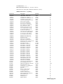
PHASE
METER
USER
MANUAL
Manual page 1
Geachte klant,
Wij danken u hartelijk voor uw keuze en het vertrouwen dat u in ons produkt stelt.
U deed een goede keus, dit produkt is ontworpen door en voor professionele gebruikers.
Er is gebruik gemaakt van onze enorme "know how" in mengtafel en signaal processor technieken en dit
gekombineerd met hoogwaardige komponenten geeft u de zekerheid van een lange gebruiksduur.
Bovenstaande eigenschappen resulteren in een zeer betrouwbaar en bedrijfszeker
eindprodukt.
Deze gebruiksaanwijzing helpt u in het optimaal benutten van alle mogelijkheden die dit
produkt in zich heeft.
Wij excuseren ons voor het feit dat deze gebruiksaanwijzing uitsluitend in het engels verkrijgbaar is.
Dit is een gevolg van het feit dat 99% van onze produkten geexporteerd worden en het engels de algemeen
aanvaarde internationale voertaal is.
Mocht u nog vragen hebben dan kunt u zich altijd tot onze dealers wenden.
Dear client,
Thank you for choosing this product.
This product is designed by specialists in the field of professional audio and is intended to be used as
a professional tool.
We are confident that you will be using this product for many years to come, and wish you much
success.
We always value suggestions from our clients, and we would therefore be grateful if you could
complete and return the questionnaire included at the back of this manual, once you have become
familiar with this product. We will certainly learn from your comments, and very much appreciate
your time doing this.
With kind regards,
Duco de Rijk
President
D&R ELECTRONICA WEESP B.V.
Rijnkade 15B
1382 GS WEESP-HOLLAND
The Netherlands
Phone: 0294-418 014
Fax: 0294-416 987
Website: http://www.d-r.nl
E-mail:
[email protected]
Manual page 2
PHASE METER MANUAL
DESCRIPTION
D&R 's phase meter is a measuring device that indicates the phase relation between two input signals.
A scale of 11 LED's indicate a phase relation between 0 degrees and 180 degrees.
The first 6 LED's are green and the second 5 LED's are red. The green area indicates acceptable phase
errors for mono compatibility, an in/phase sign is printed above the green area.
The red area is the indication that serious phase errors are present between the two input signals. An out of
phase sign is printed above the red area.
To avoid misreading special circuitry is designed to cancel any reading when one of the input signals is 20dB
below the other input signal. If only one signal is fed into the unit no reading will be displayed.
A simple test to check your phase meter is to feed two identical signals in to the left and right inputs of the
Phase meter. No reading will be displayed indicating no phase errors. As soon as you reverse the phase of
one of the signals by 180 degrees, (reversed wiring) a full 180 degrees indication will be displayed.
INSTALLATION
The phase meter is designed to read the phase relation between signals between -20dB and +20dB. A good
point of wiring is the main output of a mixing console or the input of a recording device.
For ease of wiring both inputs are paralleled, the inputs are unbalanced with signal on the tip and both ring
and sleeve wired to ground. The Phase meter can be wired in series with the signal leads that need to be
measured.
POWERING
The unit is normally factory set to be connected to your local mains voltage.
This could be either 115 volt or 230 volt, or a voltage close to these values.
The units has a three wire mains cord for proper grounding of the device.
Please read the following safety instructions for your and your environments safety.
We hope that this device gives you the information to create transparent recordings without any hidden
problems in the final mix.
D&R Electronica Weesp b.v., rijnkade 15B, 1382 GS Weesp-The Netherlands
Manual page 3
SPECIFICATIONS
Attack:
Release:
Reading:
Power:
300mSec (Vu type of reading)
300mSec (Vu type of reading)
Between -20dB and +20dB (Only when both input signals are present)
(There is no reading with one input signal present)
115/230volt 50/60Hz
Manual page 4
DECLARATION OF CONFORMITY
Manufacturers Name:
D&R Electronica Weesp b.v.
Manufacturers Address:
Rijnkade 15B,
1382 GS Weesp,
The Netherlands
declares that the product
PHASE METER
conforms to the following product specifications:
EMC:
EN 55022: 1987
CISPR 22 (1993) class B
EN 500082-1 (1992)
Supplementary Information:
The products herewith complies with the requirements of the EMC Directive 89/336/EEC (1989) as
amended by the CE Marking Directive 93/68/EEC (1993).
D&R Electronica Weesp b.v.
Rijnkade 15 B
1382 GS WEESP
The Netherlands
President of Engineering
Manual page 5
PRODUCT SAFETY
This product is manufactured with the highest standards and is double checked in our quality control
department for reliability in the "HIGH VOLTAGE" section.
CAUTION
Never remove any panels, or open this equipment. No user servicable parts inside.
Equipment power supply must be grounded at all times.
Only use this product as described, in user manual or brochure.
Do not operate this equipment in high humidity or expose it to water or other liquids.
Check the AC power supply cable to assure secure contact.
Have your equipment checked yearly by a qualified dealer service center.
Hazardous electrical shock can be avoided by carefully following the above rules.
EXTRA CAUTION FOR LIVE SOUND
Ground all equipment using the ground pin in the AC power supply cable.
Never remove this pin. Ground loops should be eliminated only by use of isolation transformers for all inputs
and outputs. Replace any blown fuse with the same type and rating only after equipment has been
disconnected from AC power.
If problem persists, return equipment to qualified service technician
PLEASE READ THE FOLLOWING INFORMATION
Especially in sound equipment on stage the following information is essential to know.
An electrical shock is caused by voltage and current, actually it is the current that causes the shock.
In practise the higher the voltage the higher the current will be and the higher the shock.
But there is another thing to consider and it is resistance.
When the resistance in Ohms is high between two poles, the current will be low and vica versa.
All three of these; voltage, current. and resistance are important in determining the effect of an electrical
shock.
However, the severity of a shock primarily determined by the amount of current flowing through a person.
A person can feel a shock because the muscles in a body respond to electrical current and because the heart
is a muscle it can affect, when the current is high enough.
Current can also be fatal when it causes the chest muscles to contract and stop breathing. At what potential is
current dangereous.
Well the first feeling of current is a tingle at 0.001 Amp of current.
The current between 0.1 Amp and 0.2 Amp is fatal.
Imagine that your home fuses of 20 Amp can handle 200 times more current than is necessary to kill. How
does resistance affect the shock a person feels.
A typical resistance between one hand to the other in "dry" condition could well over 100,000 Ohm.
If you are playing on stage your body is perspiring extensively and your body resistance is lowered
by more than 50%. This is a situation in which current can easily flow.
Current will flow when there is a difference in ground potential between equipment on stage and in the P.A.
system. Please do check if there is any potential between the housing of the mikes and the guitarsynth amps,
which will be linked by your body on stage. Imagine, a guitar in your hand and your lips close to the mike! A
ground potential difference of above 10 volts is not unusual, in improperly wired buildings it can possibly be as
high as 240 volts.
Manual page 6
Allthough removing the ground wire sometimes cures a system hum, it will create a very hazardeous situation
for the performing musician.
Always earth all your equipment by the grounding pin in your mains plug.
Hum loops should be only cured by proper wiring and isolation input/output transformers.
Replace fuses always with the same type and rating after the equipment has been turned off and unplugged.
If the fuse blows again you have an equipment failure, do not use it again and return it to your dealer for repair.
And last but not least be carefull not to touch a person being shocked as you, yourself could also be shocked.
Once removed from the shock, have someone send for medical help inmediately
Always keep the above mentioned information in mind when
using electrically powered equipment.
Manual page 7
PHASE
METER
SERVICE
MANUAL
Manual page 9
ONTWIKKELING - 1 **
Date: 19-07-96 [17:491 B I L L 0 F M A T E R I A L
D & R Electronica Weesp BV ( SERVICE-MANUAL ) Comp: 1
60898514 Phasemeter + verpakking
Articlecode
Description
Quantity
Un
.10250345
.10400216
.10401241
.10401250
.10600180
.10250342
.10400279
.10400287
.10400292
.10400297
.10600512
.10250320
.10250321
.10250316
.10250307
.10250304
.10600394
.10600395
.10300166
.10300519
.10600432
.10201198
.10201195
.10950582
.10250333
.10350517
.10350829
.10350852
.10350705
.10350717
.10350729
.10350731
.10350736
.10350737
.10350741
.10350744
.10350749
.10350753
.10350756
.10990675
.10250340
.10250359
10600174
10800924
10700975
10101199
10500084
10600437
10600436
10150093
10250386
10250387
10600493
20851198
20851195
10800956
10700694
10800275
Brugcel B80C1000 (rond)
Condensator ker 18p R2.5
Condensator ker 100nF/32V R5.0
Condensator poly 4n7 R5.0
Connector netaanslklem 2p 5mm
Diode 1N4148 (signaal)
Elco luF 50V radiaal R5.0
Elco 47uF 25V radiaal R5.0
Elco 10OuF 25V radiaal R5.0
Elco 100OuF 40V axiaal
Header recht 4p lock (R 2.54)
Ic 7815 T0220 SGS (volt.reg)
Ic 7915 T0220 SGS (volt.reg)
Ic LM-339 (comparator)
Ic NE-5532 AP TI (dual-opamp)
Ic TL-072 CP TI (dual-opamp)
Ic-voet 8 pins (vork-contact)
Ic-voet 14 pins (vork-contact)
Instelpot 10-turn 22k (T18)
Instelpot 10-turn look (T18)
Jack chassis break
Print PS 3VA phasemeter
Print Phase-1A (phasemeter)
Printtrafo 2x115V->2x18V 3.OVA
Transistor BC-327/25 (pnp)
Weerstand 1/4W OE
Weerstand 1% 1/4W 1k07
Weerstand 1% 1/4W 15k0
Weerstand 5% 1/4W 10E
Weerstand 5% 1/4W 100E
Weerstand 5% 1/4W iko
Weerstand 5% 1/4W 1k5
Weerstand 5% 1/4W 3k9
Weerstand 5% 1/4W 4k7
Weerstand 5% 1/4W lok
Weerstand 5% 1/4W 18k
Weerstand 5% 1/4W 47k
Weerstand 5% 1/4W look
Weerstand 5% 1/4W 180k
Zekeringhouder print + kap
Zenerdiode 2V4 400mW
Zenerdiode 15V0 400mW
Conn: 4p wired: 402-04/2*20cm
Doos Randapparatuur 9.511
Dubbelzijdig plakband 12mm dun
Front phase ineter 9.511
Isolatieplaat 9.511 randapp.PVC
Jack fiberring (zwart)
Jack moer
Kast 9.5” 1HE version c
Led 3mm green round
Led 3mm red round
Netsnoer 3 aderig soldeer
Print bestukt PS 3VA (phasem.)
Print bestukt Phase-1
Schuimblok 9.511
Soldeerlip groot
Sticker OUT/IN
1.0000
6.0000
13.0000
2.0000
2.0000
3.0000
4.0000
1.0000
9.0000
2.0000
8.0000
1.0000
1.0000
3.0000
1.0000
2.0000
3.0000
3.0000
2.0000
1.0000
4.0000
1.0000
1.0000
1.0000
1.0000
11.0000
10.0000
1.0000
2.0000
1.0000
2.0000
1.0000
3.0000
1.0000
4.0000
5.0000
3.0000
5.0000
2.0000
1.0000
1.0000
5.0000
2.0000
1.0000
20.0000
1.0000
1.0000
4.0000
4.0000
1.0000
5.0000
5.0000
1.0000
1.0000
1.0000
2.0000
1.0000
2.0000
st
st
st
st
st
st
st
st
st
st
st
st
st
st
st
st
st
st
st
st
st
st
st
st
st
st
st
st
st
st
st
st
st
st
st
st
st
st
st
st
st
st
st
st
C11
st
st
st
st
st
st
st
st
st
st
st
st
st
Manual page 10
10800421
10700790
10700691
Sticker WARNING (rood)
Taptite M3x6 verzkop/pozidr/zw
Trekontlasting voeding rond
1.0000
8.0000
1.0000
st
st
st
Manual page 11
Phase1b.sch-1 - Thu Aug 19 17:21:39 1999