1
User Manual for
HECOM650/HE800COM650
&
HECOS600/HE800COS600
CANOpen Master and Slave
Rev 1
Rev 2
Rev 3
Initial Release
Added OCS Interface chapter
Added OCS Interface chapter
D.Taylor
D.Taylor
D.Taylor
MAN0576-03-En
20 Feb 2003
11 Sept 2008
12 Oct 2008
EO 09-0009
PREFACE
CANopen Smartstack Manual
MAN0576-03-En
PREFACE
This manual explains how to use the Horner APG HSyCon software product.
Copyright © 2001 Horner APG, LLC., 640 North Sherman Drive, Indianapolis, Indiana 46201-3899. All rights
reserved. No part of this publication may be reproduced, transmitted, transcribed, stored in a retrieval
system, or translated into any language or computer language, in any form by any means, electronic,
mechanical, magnetic, optical, chemical, manual or otherwise, without the prior agreement and written
permission of Horner APG, LLC.
Information in this document is subject to change without notice and does not represent a commitment on
the part of Horner APG, LLC.
Windows 95, Windows 98, and Windows NT are registered trademarks of Microsoft
Corporation.
DeviceNet is a trademark of Open DeviceNet Vendors Association (ODVA).
Profibus is a trademark of Siemens.
Cscape, CsCAN, and SmartStack are trademarks of Horner APG, LLC.
For user manual updates and technical support contact :
Horner APG (USA)
Horner APG (Europe)
Technical Support (317) 916-4274
Technical Support +353-21-4321266
web-site www.horner-apg.com.
web-site www.horner-apg.com
LIMITED WARRANTY AND LIMITATION OF LIABILITY
Horner APG, LLC. ("HE-APG") warrants to the original purchaser that the Operator Station manufactured by HE is free from defects
in material and workmanship under normal use and service. The obligation of HE-APG under this warranty shall be limited to the
repair or exchange of any part or parts which may prove defective under normal use and service within two (2) years from the date
of manufacture or eighteen (18) months from the date of installation by the original purchaser whichever occurs first, such defect to
be disclosed to the satisfaction of HE-APG after examination by HE-APG of the allegedly defective part or parts. THIS WARRANTY
IS EXPRESSLY IN LIEU OF ALL OTHER WARRANTIES EXPRESSED OR IMPLIED INCLUDING THE WARRANTIES OF
MERCHANTABILITY AND FITNESS FOR USE AND OF ALL OTHER OBLIGATIONS OR LIABILITIES AND HE-APG NEITHER
ASSUMES, NOR AUTHORIZES ANY OTHER PERSON TO ASSUME FOR HE-APG, ANY OTHER LIABILITY IN CONNECTION
WITH THE SALE OF THE Operator Station. THIS WARRANTY SHALL NOT APPLY TO THE Operator Station OR ANY PART
THEREOF WHICH HAS BEEN SUBJECT TO ACCIDENT, NEGLIGENCE, ALTERATION, ABUSE, OR MISUSE. HE MAKES NO
WARRANTY WHATSOEVER IN RESPECT TO ACCESSORIES OR PARTS NOT SUPPLIED BY HE. THE TERM "ORIGINAL
PURCHASER", AS USED IN THIS WARRANTY, SHALL BE DEEMED TO MEAN THAT PERSON FOR WHOM THE Operator
Station IS ORIGINALLY INSTALLED. THIS WARRANTY SHALL APPLY ONLY WITHIN THE BOUNDARIES OF THE
CONTINENTAL UNITED STATES.
In no event, whether as a result of breach of contract, warranty, tort (including negligence) or otherwise, shall HE-APG or its
suppliers be liable of any special, consequential, incidental or penal damages including, but not limited to, loss of profit or revenues,
loss of use of the products or any associated equipment, damage to associated equipment, cost of capital, cost of substitute
products, facilities, services or replacement power, down time costs, or claims of original purchaser's customers for such damages.
PAGE 2 of 111
EO 09-0009
© Horner APG.This drawing is the property of Horner APG. and shall not be disclosed or reproduced except as specifically authorised.
PREFACE
CANopen Smartstack Manual
MAN0576-03-En
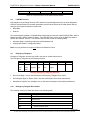
List of Revisions
Index Date
20-Feb-03
Version
Chapter Revision
01
All
Initial release.
PAGE 3 of 111
EO 09-0009
© Horner APG.This drawing is the property of Horner APG. and shall not be disclosed or reproduced except as specifically authorised.
PREFACE
CANopen Smartstack Manual
MAN0576-03-En
TABLE OF CONTENTS
PREFACE ..................................................................................................................................................... 2
LIMITED WARRANTY AND LIMITATION OF LIABILITY ............................................................................. 2
CHAPTER 1: INTRODUCTION .................................................................................................................... 7
1.1
Scope ........................................................................................................................................... 7
1.2
Introduction................................................................................................................................... 7
1.3
Installing and Removing a SmartStack Module ........................................................................... 7
Removing SmartStack Modules................................................................................................................. 8
1.4
Installation of the COM module in an OCS/TIU ........................................................................... 9
1.5
CANOpen Network ..................................................................................................................... 10
1.6
Communication Profile, Device Profile and Device Type .......................................................... 10
1.6.1
Communication Profile 301 ........................................................................................................ 10
1.6.2
NMT State Machine (State Diagram) ......................................................................................... 10
1.6.3
Communication Characteristics in the different NMT States ..................................................... 12
CHAPTER 2: HSYCON INSTALLATION .................................................................................................... 13
2.1
System Requirments .................................................................................................................. 13
2.2
System Installation ..................................................................................................................... 13
2.3
Installation of the System Configurator HSyCon........................................................................ 13
2.4
Licensing .................................................................................................................................... 14
2.5
Scope of functions of the basic version (unlicensed) Fieldbus Modules ................................... 15
CHAPTER 3: GETTING STARTED – CONFIGURATION .......................................................................... 17
3.1
Overview of Communication Types ........................................................................................... 17
3.2
Configuration of a SmartStack CANOpen Master PDO Telegram to any CANOpen Slave ...... 17
3.3
Configuration of a SmartStack CANOpen Slave to any CANOpen Master ............................... 18
3.4
Configuration for SDO Communication ...................................................................................... 19
3.5
Configuration of a SmartStack CANopen Node to any CANopen Master (SDO) ...................... 20
3.6
Configuration of a SmartStack CANopen Master to any CAN Device for Send/Receive
transparent (CAN) .................................................................................................................................... 21
3.7
Configuration of a SmartStack CANopen Node to any CAN Device for Send/Receive
transparent (CAN) .................................................................................................................................... 22
CHAPTER 4: CONFIGURATION OF CANOPEN WITH HSYCON ............................................................ 24
4.1
Setting up the CANOpen Configuration ..................................................................................... 24
4.2
EDS files..................................................................................................................................... 24
4.3
Insert Master .............................................................................................................................. 24
4.4
Master Configuration .................................................................................................................. 25
4.5
Replace Master .......................................................................................................................... 26
4.6
Insert Node ................................................................................................................................. 26
4.7
Node Configuration .................................................................................................................... 28
4.8
Overview of Node Configuration ................................................................................................ 30
4.9
Device Profile and Device Type ................................................................................................. 30
4.10
Process Data Configuration - Selection of PDO ........................................................................ 30
4.11
PDO Communication Parameter (PDO Characteristic) ............................................................. 31
4.12
Receive PDO characteristics ..................................................................................................... 32
4.13
Creating Receive PDOs ............................................................................................................. 32
4.14
Transmit PDO characteristics .................................................................................................... 33
4.15
Creating Transmit PDOs ............................................................................................................ 34
4.16
PDO Contents Mapping - Arrange a PDO ................................................................................. 35
4.17
Node BootUp .............................................................................................................................. 36
4.18
Node supervision - Nodeguarding and Lifeguarding ................................................................. 37
4.19
Object Configuration .................................................................................................................. 37
4.20
OPC Objects .............................................................................................................................. 38
4.21
OPC User Defined Objects ........................................................................................................ 38
4.22
Replace Node ............................................................................................................................ 38
PAGE 4 of 111
EO 09-0009
© Horner APG.This drawing is the property of Horner APG. and shall not be disclosed or reproduced except as specifically authorised.
PREFACE
CANopen Smartstack Manual
MAN0576-03-En
CHAPTER 5: SETTINGS ............................................................................................................................ 41
5.1
Device Assignment .................................................................................................................... 41
5.2
COM Serial Driver ...................................................................................................................... 41
5.3
Bus Parameters ......................................................................................................................... 42
5.4
CANopen Master ........................................................................................................................ 43
5.5
Master Settings .......................................................................................................................... 43
5.6
Addressing Mode ....................................................................................................................... 45
5.7
Global Settings ........................................................................................................................... 45
5.8
CANopen Node .......................................................................................................................... 46
5.9
Node Settings ............................................................................................................................. 46
5.10
Project Information ..................................................................................................................... 47
5.11
Path ............................................................................................................................................ 47
5.12
Languages.................................................................................................................................. 47
5.13
Start Options .............................................................................................................................. 48
CHAPTER 6: ONLINE FUNCTIONS .......................................................................................................... 50
6.1
Introduction................................................................................................................................. 50
6.2
Downloading the Configuration .................................................................................................. 50
6.3
Firmware Download ................................................................................................................... 51
6.4
Firmware / Reset ........................................................................................................................ 51
6.5
Start/Stop Communication ......................................................................................................... 52
6.6
Diagnostic Functions .................................................................................................................. 52
6.7
Live List ...................................................................................................................................... 53
6.8
Debugmode (CANopen)............................................................................................................. 53
6.9
The Debugwindow ..................................................................................................................... 53
6.10
CANopen Node specific Diagnostic ........................................................................................... 54
6.11
Emergency Telegrams ............................................................................................................... 56
6.12
Global State Field ....................................................................................................................... 56
6.13
Extended Device Diagnostic ...................................................................................................... 58
6.14
User Data Transfer ..................................................................................................................... 58
6.15
I/O-Monitor ................................................................................................................................. 59
6.16
Read Objects (SDO Upload) ...................................................................................................... 60
6.17
Write Object (SDO Download) ................................................................................................... 60
6.18
Message Monitor ........................................................................................................................ 60
6.19
Message Monitor for Using LSS/LMT ........................................................................................ 61
6.20
Message Monitor for Sending or Receiving Transparent CAN Telegrams ................................ 69
6.21
Message Monitor for Sending CAN Telegrams (transparent).................................................... 69
6.22
Message Monitor for Receiving CAN Telegrams (transparent) ................................................. 70
CHAPTER 7: FILE, PRINT, EDIT, EXPORT AND VIEW ........................................................................... 74
7.1
File.............................................................................................................................................. 74
7.1.1
Open........................................................................................................................................... 74
7.1.2
Save and Save As ...................................................................................................................... 74
7.1.3
Close .......................................................................................................................................... 74
7.2
Print ............................................................................................................................................ 74
7.3
Export Functions ........................................................................................................................ 75
7.3.1
DBM Export ................................................................................................................................ 75
7.3.2
CSV Export................................................................................................................................. 75
7.3.2.1 Description of the Parameter Settings ....................................................................................... 76
7.3.2.2 Description of the Parameter DataType ..................................................................................... 76
7.3.2.3 Description of the Parameter DataPosition ................................................................................ 76
7.3.2.4 Example of a CSV file ................................................................................................................ 77
7.4
Edit ............................................................................................................................................. 78
7.4.1
Cut, Copy and Paste .................................................................................................................. 78
7.4.2
Delete ......................................................................................................................................... 79
7.4.3
Replace ...................................................................................................................................... 79
7.5
View of the Configuration ........................................................................................................... 79
7.5.1
Device Table .............................................................................................................................. 79
PAGE 5 of 111
EO 09-0009
© Horner APG.This drawing is the property of Horner APG. and shall not be disclosed or reproduced except as specifically authorised.
PREFACE
CANopen Smartstack Manual
MAN0576-03-En
7.5.2
Address Table ............................................................................................................................ 80
7.5.3
ID Table ...................................................................................................................................... 80
7.5.4
SDO Table.................................................................................................................................. 81
7.6
View Menu SyCon ...................................................................................................................... 82
7.6.1
Logical Network View ................................................................................................................. 82
7.6.2
Toolbars ..................................................................................................................................... 82
7.6.3
Status Bar................................................................................................................................... 82
CHAPTER 8: ERROR CODES ................................................................................................................... 84
8.1
CIF Serial Driver Error Numbers (-20 .. -71) .............................................................................. 84
9.1
Extended Device Diagnostic Master .......................................................................................... 85
9.1.1
PLC_TASK Common Variables ................................................................................................. 85
9.1.2
CAN_TASK Common Variables................................................................................................. 86
9.1.3
CAN_TASK Node Running State ............................................................................................... 87
9.1.4
CAN_TASK Communication Error ............................................................................................. 87
9.1.5
Queues ....................................................................................................................................... 88
9.1.5.1 CAN_TASK Nodeguard Inputqueue .......................................................................................... 88
9.1.5.2 CAN_TASK Management Inputqueue ....................................................................................... 88
9.1.5.3 CAN_TASK Emergency Inputqueue .......................................................................................... 89
9.1.5.4 CAN_TASK Transmit Queue ..................................................................................................... 89
9.1.6
CAN_TASK CMS Domain Services ........................................................................................... 89
9.1.7
CAN_TASK Timeout Counter .................................................................................................... 90
9.1.8
CAN_TASK Node Init Counter ................................................................................................... 91
9.2
Extended Device Diagnostic Node ............................................................................................ 92
9.2.1
PCL_TASK Common Variables ................................................................................................. 92
9.2.2
COS_TASK Common Variables ................................................................................................ 92
9.2.3
COS_TASK User Communication ............................................................................................. 94
9.2.4
COS_TASK Node Management ................................................................................................ 95
9.2.5
COS_TASK PDO Transfer ......................................................................................................... 96
9.2.6
COS_TASK SDO Transfer ......................................................................................................... 96
9.2.7
COS_TASK Object Dictionary.................................................................................................... 98
9.2.8
COS_TASK Receive Queue ...................................................................................................... 98
9.2.9
COS_TASK Transmit Queue ..................................................................................................... 98
9.3
COB-ID (Predefined Connection Set) ........................................................................................ 99
9.4
Object Dictionary ...................................................................................................................... 100
9.4.1
Object Name and Object Code ................................................................................................ 100
9.4.2
Object Dictionary Data Types .................................................................................................. 101
9.4.3
Object Dictionary Profile........................................................................................................... 102
9.5
Communication Profile, Device Profile and Device Type ........................................................ 105
9.5.1
Communication Profile 301 ...................................................................................................... 105
9.5.2
Device Profile 401 - Device Profile for I/O Modules ................................................................. 105
9.5.3
Device Profile 402 - Device Profile for Drives .......................................................................... 106
9.5.4
Device Profile 406 - Device Profile for Encoder ....................................................................... 106
9.6
PDO Mapping Method.............................................................................................................. 107
9.7
NMT State Machine (State Diagram) ....................................................................................... 107
9.7.1
Communication Characteristics in the different NMT States ................................................... 108
9.8
LSS/LMT Services ................................................................................................................... 109
9.9
Emergency Telegrams ............................................................................................................. 109
9.10
Emergency Telegram Error Codes .......................................................................................... 109
CHAPTER 10: GLOSSARY ...................................................................................................................... 111
PAGE 6 of 111
EO 09-0009
© Horner APG.This drawing is the property of Horner APG. and shall not be disclosed or reproduced except as specifically authorised.
CH. 1: INTRODUCTION
CANopen Smartstack Manual
MAN0576-03-En
CHAPTER 1: INTRODUCTION
1.1
Scope
This manual is intended to give the user enough information to configure an OCS/RCS/TIU with a
SmartStack COM Module correctly. It does not provide detailed information of the theory behind the
fieldbus protocols. HSyCon, is an easy-to-use Windows-based configuration package for use with the
SmartStack COM range of fieldbus modules. The software user’s guide is contained in this manual.
Cscape and Cbreeze are also easy-to-use Windows-based configuration packages for use with the
OCS/RCS and TIU platforms respectively.
A basic level of understanding of Microsoft Windows technology and operation is assumed. The manual
assumes that the user is familiar with Windows 95, Windows 98 or Windows NT.
1.2
Introduction
The Fieldbus Smartstack module range adds a range of Master or Slave capable fieldbus protocols to the
OCS/RCS and TIU families. These modules are self-contained units which provide access to the fieldbus
network via a dual port ram interface on the SmartStack backplane. They are simple install and
configure, requiring only three stages to get them operational, these are :
1. Physical installation and connection.
2. Configuration of the fieldbus interface.
3. Configuration of Cscape / Cbreeze to map the fieldbus data.
The system is comprised of two separate software functions, the fieldbus interface software running
independently in the COM module and the OCS/TIU firmware running in the main module. Data and
commands are exchanged via a dual port ram interface. The configuration of the COM module is via the
RS232 serial port on the module. For correct operation the number of registers assigned in the OCS
must match the number required by the Master or Slave module configuration.
The Smartstack module should be configured with the OCS/TIU first as otherwise it will be held in reset
and cannot be configured.
1.3
Installing and Removing a SmartStack Module
The following section describes how to install and remove a SmartStack Module.
Caution: To function properly and avoid possible damage, do not install more than four Smart
Stack Modules per OCS / RCS or TIU.
Do not attempt to install or remove a SmartStack module with the power on.
Installing SmartStack Modules
1. Hook the tabs. Each SmartStack Module has two tabs that fit into slots located on the OCS. (The
slots on the OCS are located on the back cover.)
2. Press the SmartStack Module into the “locked” position, making sure to align the SmartStack Module
fasteners with the SmartStack receptacles on the OCS.
PAGE 7 of 111
EO 09-0009
© Horner APG.This drawing is the property of Horner APG. and shall not be disclosed or reproduced except as specifically authorised.
CH. 1: INTRODUCTION
CANopen Smartstack Manual
MAN0576-03-En
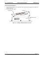
Removing SmartStack Modules
1. Using a flathead screwdriver, lever up the end of the SmartStack Module (opposite end to tabs) and
swing the module out.
2. Lift out the tabs of the module.
SmartStack Tab
Fastener
Mating Pins
OCS Back Cover
Figure 2.1 – Installing a SmartStack Module in an OCS
PAGE 8 of 111
EO 09-0009
© Horner APG.This drawing is the property of Horner APG. and shall not be disclosed or reproduced except as specifically authorised.
CH. 1: INTRODUCTION
1.4
CANopen Smartstack Manual
MAN0576-03-En
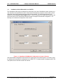
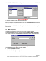
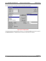
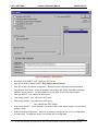
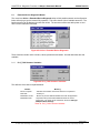
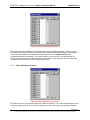
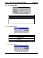
Installation of the COM module in an OCS/TIU
The SmartStack COM range are installed in a similar way to any other SmartStack module, however, the
user should be aware that while the Auto Config function will report the presence of the module it cannot
assign the amount of I/O required, the user must do this manually. To configure the amount of I/O
required use the Controller > I/O Configure menu. If the Com module is on a base then double click the
left mouse button on the relevant base and then double click again on the Module config button. The
following menu allows the configuration of the module :
Figure 1.1: SmartStack COM Module Configuration in Cscape / Cbreeze.
Select the Module Configuration tab and enter the register types and number required. Click OK to close
the windows and download the configuration to the OCS /TIU. For further details of configuring OCS /TIU
units please see the relevant module user manual.
PAGE 9 of 111
EO 09-0009
© Horner APG.This drawing is the property of Horner APG. and shall not be disclosed or reproduced except as specifically authorised.
CH. 1: INTRODUCTION
1.5
CANopen Smartstack Manual
MAN0576-03-En
CANOpen Network
CAN is an acronym for Controller Area Network. The CAN specification describes the physical interface,
the telegram structure and the secure transmission of a CAN telegram. It describes the transmission and
the reception of telegrams. The CAN telegram consists (simplified) of a telegram identifier and 0 to 8
bytes of data. The meaning of the telegram identifier and of the max. 8 bytes of user data is not
described, e.g. it does not say anything about the application layer.
CANopen is an open standard protocol based on CAN. It specifies the meaning of the telegram
identifiers and of the 0 to 8 bytes of user data. It is a standard application layer defined by the CIA (CAN
In Automation) specification DS 301.
CANopen is network concept and determines what data and what services are to be transmitted the
meaning of the data for the individual device classes. It provides functions for the network initialization,
guarding and configuration. It is a very flexible protocol.
A CANopen device can be described generally as being composed of three components:
communication, objects and application.
Component
Description
•
Communication
The communication unit contains the mechanism for the transport of data
according to the CANopen specification over CAN.
•
Object dictionary
The object dictionary is the connection between the application unit and
the communication unit. It contains configuration data and device
information. All entries have an object index (index) and a subindex.
•
Application
The application unit describes the function of the CANopen device.
Table 1: Components of the CANopen Device Model
1.6
Communication Profile, Device Profile and Device Type
The Communication Profile DS 301 specifies how to communicate. The Device Profiles DS 401xx
specify, what is communicated :
Device Profile
Description
301
Common communication profile according to DS301
401
Device profile for I/O modules
402
Device profile for drives
406
Device profile for encoder
Table 1: Device Profile and Device Type
1.6.1
Communication Profile 301
The communication profile DS 301 is a common profile. It is the basis of CANopen communication and
lays down how the devices communicate on the CANopen network.
1.6.2
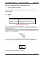
NMT State Machine (State Diagram)
NMT stands for Network Management. This state machine defines and controls the CANOpen fieldbus
states, the following diagram shows the possible states of a CANopen Node.
PAGE 10 of 111
EO 09-0009
© Horner APG.This drawing is the property of Horner APG. and shall not be disclosed or reproduced except as specifically authorised.
CH. 1: INTRODUCTION
CANopen Smartstack Manual
MAN0576-03-En
Figure 1: NMT-State Machine
Number
1
Meaning
At Power on the initialisation state is entered autonomously
2
Initialisation finished -enter PRE_OPERATIONAL automatically
3, 6
Start_Remote_Node indication
4, 7
Enter_PRE-OPERATIONAL_State indication
5, 8
Stop_Remote_Node indication
9, 10, 11
Reset_Node indication
12, 13, 14 Reset_Communication indication
Table 2: Description NMT-State Machine
PAGE 11 of 111
EO 09-0009
© Horner APG.This drawing is the property of Horner APG. and shall not be disclosed or reproduced except as specifically authorised.
CH. 1: INTRODUCTION
1.6.3
CANopen Smartstack Manual
MAN0576-03-En
Communication Characteristics in the different NMT States
The following table shows the possible communication in the respective NMT states.
Communication
Initialization
Pre-Operational
Operational
•
PDO
SDO
•
•
SYNC
•
•
Time Stamp
•
•
EMCY
•
•
•
•
BootUp
NMT
Stopped
•
•
Table 3: Communication in the different NMT States
PAGE 12 of 111
EO 09-0009
© Horner APG.This drawing is the property of Horner APG. and shall not be disclosed or reproduced except as specifically authorised.
CH. 2 INSTALLATION
CANopen Smartstack Manual
MAN0576-03-En
CHAPTER 2: HSYCON INSTALLATION
2.1
System Requirments
•
PC with 486-, Pentium processor or higher.
•
Windows 95/98/ME, Windows NT/2000/XP.
•
Free disk space: 30 - 80 Mbyte.
•
CD ROM drive.
•
RAM: min. 16 Mbyte.
•
Graphic resolution: min. 800 x 600 pixel.
•
Windows 95: Service Pack 1 or higher.
•
Windows NT: Service Pack 3 or higher.
•
Keyboard and Mouse.
2.2
System Installation
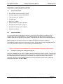
It is recommended that all application programs on the system are closed before installation begins.
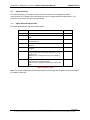
Insert the CD in the local CD ROM drive. The installation program will start by itself (if Autostart is
enabled). Otherwise change into the root directory on the CD and start Autorun.exe (Autostart disabled).
Note: Administrator privileges are required on Windows NT/2000/XP systems for installation!
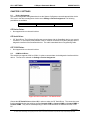
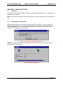
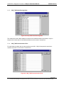
The installation program asks for the components to install. Answer these questions with Yes or No. Tick
‘No’ for the OPC Server function, it is not included with this installation pack.
Figure 1: Selection for the Installation of the licensed System Configurator (without OPC)
2.3
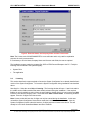
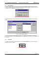
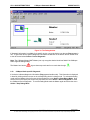
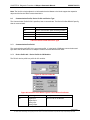
Installation of the System Configurator HSyCon
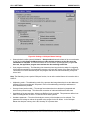
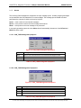
During the installation the user name, company name and license code must be entered. Otherwise the
HSystem Configurator will only work in basic version mode. In this case, all functions are available, but
the configuration is limited to two devices on the network, this is usually sufficient for Slave devices.
Follow the instructions of the installation program by selecting the fieldbus system to be installed and
answer all the questions with OK or NEXT.
PAGE 13 of 111
EO 09-0009
© Horner APG.This drawing is the property of Horner APG. and shall not be disclosed or reproduced except as specifically authorised.
CH. 2 INSTALLATION
CANopen Smartstack Manual
MAN0576-03-En
Figure 2: Enter the Name, the Company Name and the Licensecode
Note: The License code 0123456789ABCDEF is not a valid code and is only used for explanation
purpose, the code is case sensitive.
It is necessary to fill in the Name,Company Name and License code fields, the rest are optional.
The installation program copies the program files, GSD or EDS files and Bitmaps to the PC. Finally the
following files are entered in the system Registry.
•
System DLLs
•
The application
2.4
Licensing
This section describes the steps required to license the System Configurator for an already installed basic
version of the System Configurator. To license the System Configurator during installation was described
above.
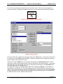
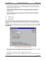
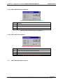
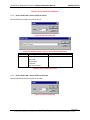
Start HsyCon. Select the menu Help > Licensing. The licensing window will open. Listed in the table in
the middle are the fieldbus modules that were already selected during the installation. If the required
fieldbus is not in the table then select it from the upper table by double clicking on it or by select and Add.
Enter the name and the company name. Select the button Enter License Code. The following windows
appear. Enter the 16 digits of the license code.
Note: License codes with less than 16 digits can only be entered during the installation. In this case
uninstall the System Configurator first and then restart the installation and enter the code. Also the
System Configurator (license code with less than 16 digits) expects a license in the device. This will
already be in all Horner SmartStack Master and Slave modules.
PAGE 14 of 111
EO 09-0009
© Horner APG.This drawing is the property of Horner APG. and shall not be disclosed or reproduced except as specifically authorised.
CH. 2 INSTALLATION
CANopen Smartstack Manual
MAN0576-03-En
Figure 3: Enter the License Code
Note: The license code showed above is an invalid license code and is only used for explanation.
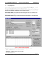
Once the license code has been entered select the OK button. The code is verified. If the license code is
valid HSyCon will display text stating that it requires to be restarted to activate the license. If the license
code is invalid the following window appears.
Figure 4: Note license code is invalid
In this case check :
•
2.5
the license code is entered properly (it is case sensitive).
Scope of functions of the basic version (unlicensed) Fieldbus Modules
The basic version and unlicensed fieldbus modules have the following functionality:
•
Full functionality for configuring up to two devices (slaves). For configuration of a Horner SmartStack
COM Slave device this is enough.
•
All diagnostic functions
PAGE 15 of 111
EO 09-0009
© Horner APG.This drawing is the property of Horner APG. and shall not be disclosed or reproduced except as specifically authorised.
CH. 2 INSTALLATION
•
CANopen Smartstack Manual
MAN0576-03-En
Open and download of an existing configuration file. If the configuration file has more than two
devices, a modification of this configuration is not possible.
PAGE 16 of 111
EO 09-0009
© Horner APG.This drawing is the property of Horner APG. and shall not be disclosed or reproduced except as specifically authorised.
CH. 3 GETTING STARTED
CANopen Smartstack Manual
MAN0576-03-En
CHAPTER 3: GETTING STARTED – CONFIGURATION
3.1
Overview of Communication Types
The CANOpen communication protocol supports several different communication objects, Table 2 below
shows some of the options supported by the Horner COM/COS SmartStack modules :
Communication
• PDO (CANopen)
• SDO (CANopen)
• Send/Receive Transparent(CAN)
Table 4: Overview of CANopen Communication Types
3.2
Configuration of a SmartStack CANOpen Master PDO Telegram to any CANOpen Slave
The following describes the steps to configure a SmartStack CANOpen Master PDO Telegram to any
CANOpen Slave :
Action
Menu in the System Configurator
•
Create a new project
File > New > CANopen
•
Copy EDS file of CANopen Node, if Node is not
available yet
File > Copy EDS
•
Select SmartStack CANopen Master
Insert > Master
•
Select CANopen Node and set Node address
Insert > Node
•
Set PDO
Left mouse click on the Node, then
•
Set Offset address (*1)
Settings > Node Configuration
•
Set Bus Parameter
Left mouse click on the Master, then
Settings > Bus Parameter
•
Set Device Assignment, if no automatic
assignment has occurred
Left mouse click on the Master, then
•
Save project
File > Save
•
Download
Left mouse click on the Master, then
Settings > Device Assignment
Online > Download
•
Live List
Left mouse click on the Master, then
Online > Live List
•
Start Debugger
Left mouse click on the Master, then
Online > Start Debug Mode
•
Device Diagnostic
•
Stop Debugger
•
Global Diagnostic
Left mouse click on the Node, then
Online > Device Diagnostic
Online > Stop Debug Mode
Left mouse click on the Master, then
Online > Global State Field
•
Transfer user data: Send data, Receive data
Left mouse click on the Master, then
Online > I/O Monitor
Table 3. Configuration of SmartStack CANOpen Master PDO to any CANOpen Slave.
PAGE 17 of 111
EO 09-0009
© Horner APG.This drawing is the property of Horner APG. and shall not be disclosed or reproduced except as specifically authorised.
CH. 3 GETTING STARTED
3.3
CANopen Smartstack Manual
MAN0576-03-En
Configuration of a SmartStack CANOpen Slave to any CANOpen Master
The following table describes the steps to configure a PDO telegram for a SmartStack CANOpen Slave to
any CANOpen Master :
Action
Menu in the System Configurator
•
Create a new project
File > New > CANopen
•
Select SmartStack CANopen Master (*1) Insert > Master
•
Select SmartStack CANopen Node and
set Node address
Insert > Node
•
Set Bus Parameter
Left mouse click on the Master, then
Settings > Bus Parameter
•
Set Device Assignment, if no automatic
assignment has occurred
Left mouse click on the Node, then
•
Save project
File > Save
•
Download
Settings > Device Assignment
Left mouse click on the Node, then
Online > Download
•
PDO diagnostic
Left mouse click on the Node, then
Online > Extended Device Diagnostic > COS_TASK
PDO Transfer
•
Transfer user data: Send data, Receive
data
Left mouse click on the Master, then
Online > I/O Monitor
Table 4. Configuration of SmartStack CANOpen Slave PDO to any CANOpen Master.
Note: The SmartStack CANopen Node is configured via the CANopen Bus by means of an SDO
download from a configuration master. Without a configuration master the SmartStack CANopen
Node provides two send and two receive-PDOs with a default mapping for the communication.
Note (*1): Insert a SmartStack CANopen Master to the configuration. It serves as a dummy and does not
have to agree with the connected Master.
PAGE 18 of 111
EO 09-0009
© Horner APG.This drawing is the property of Horner APG. and shall not be disclosed or reproduced except as specifically authorised.
CH. 3 GETTING STARTED
3.4
CANopen Smartstack Manual
MAN0576-03-En
Configuration for SDO Communication
The following table describes the steps to configure a Smartstack CANopen Master to any CANopen
Node for SDO communication:
Action
Menu in the System Configurator
•
Create a new project
File > New > CANopen
•
Copy EDS file of CANopen
File > Copy EDS
Node, if Node is not available
yet
•
Select SmartStack CANopen
Master
Insert > Master
•
Select CANopen Node and
set Node address
Insert > Node
•
Set Bus Parameter
Left mouse click on the Master, then
Settings > Bus Parameter
•
Set Device Assignment, if no
automatic assignment has
occurred
Left mouse click on the Master, then
•
Save project
File > Save
•
Download
Settings > Device Assignment
Left mouse click on the Master, then
Online > Download
•
Live List
Left mouse click on the Master, then
Online > Live List
•
Transfer user data:
Left mouse click on the Node, then
Read objects
Online > Read Objects
Write objects
Online > Write Objects
Table 5: Smartstack master to slave SDO Configuration steps
Note (*1): If connecting to anything other than a Horner Slave then see the Slave manual for
configuration help.
PAGE 19 of 111
EO 09-0009
© Horner APG.This drawing is the property of Horner APG. and shall not be disclosed or reproduced except as specifically authorised.
CH. 3 GETTING STARTED
3.5
CANopen Smartstack Manual
MAN0576-03-En
Configuration of a SmartStack CANopen Node to any CANopen Master (SDO)
The following table describes the steps to configure a SmartStack CANopen Node to any CANopen
Master for SDO communication :
Action
Menu in the System Configurator
•
Create a new project
File > New > CANopen
•
Select SmartStack CANopen
Master (*1)
Insert > Master
•
Select SmartStack CANopen
Node and set Node address
Insert > Node
•
Set Bus Parameter
Left mouse click on the Master, then
•
Set Device Assignment, if no
automatic assignment has
occurred
Left mouse click on the Node, then
•
Save project
File > Save
•
Download
Settings > Bus Parameter
Settings > Device Assignment
Left mouse click on the Node, then
Online > Download
•
SDO Diagnostic
•
Transfer user data:
Left mouse click on the Node, then
Read objects
Online > Message Monitor
Left mouse click on the Node, then
Online > Extended Device Diagnostic
Write objects
Table 5: Configuration of a SmartStack CANopen Node to any CANopen Master (SDO)
Note (*1): Insert a SmartStack CANopen Master to the configuration. It serves as a dummy and does
not have to agree with the connected Master.
PAGE 20 of 111
EO 09-0009
© Horner APG.This drawing is the property of Horner APG. and shall not be disclosed or reproduced except as specifically authorised.
CH. 3 GETTING STARTED
3.6
CANopen Smartstack Manual
MAN0576-03-En
Configuration of a SmartStack CANopen Master to any CAN Device for Send/Receive
transparent (CAN)
The following table describes the steps to configure a Smartstack CANopen Master for send/receive CAN
telegrams (Layer 2) transparently:
Action
Menu in the System Configurator
•
Create a new project
File > New > CANopen
•
Select Smartstack CANopen Master
Insert > Master
•
Set Bus Parameter
Left mouse click on the Master, then
•
Set Device Assignment for the Master, if no
automatic assignment has occurred
Left mouse click on the Master, then
•
Save project
File > Save
•
Download on the Master
Left mouse click on the Master, then
•
Transfer user data:
Left mouse click on the Master, then
Send CAN Telegrams
Receive CAN Telegrams (*1)
Online > Message Monitor
Settings > Bus Parameter
Settings > Device Assignment
Online > Download
Table 6 : Configuration of a SmartStack CANopen Master to any CAN Device.
Note (*1): The CAN Telegram receive Identifiers are activated per message.
PAGE 21 of 111
EO 09-0009
© Horner APG.This drawing is the property of Horner APG. and shall not be disclosed or reproduced except as specifically authorised.
CH. 3 GETTING STARTED
3.7
CANopen Smartstack Manual
MAN0576-03-En
Configuration of a SmartStack CANopen Node to any CAN Device for Send/Receive
transparent (CAN)
The following table describes the steps to configure a SmartStack CANopen Node for send/receive CAN
telegrams (Layer 2) transparently:
Action
Menu in the System Configurator
•
Create a new project
File > New > CANopen
•
Select Smartstack CANopen Master
(*1)
Insert > Master
•
Select SmartStack CANopen Node
Insert > Node
•
Set Bus Parameter
Left mouse click on the Master, then
Settings > Bus Parameter
•
Set Device Assignment for the Node, if
no automatic assignment has occurred
Left mouse click on the Node, then
•
Save project
File > Save
•
Download on the Node
Settings > Device Assignment
Left mouse click on the Node, then
Online > Download
•
Transfer user data:
Left mouse click on the Node, then
Send CAN Telegrams
Receive CAN Telegrams
Online > Message Monitor
Table 9: Configuration of a Smartstack node for transparent mode.
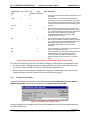
Note (*1): Insert a Smartstack CANopen Master to the configuration. It serves as a dummy and need not
agree with the connected Master.
Signal
RDY
LED Colour
Yellow
RUN
Green
ERR
Red
STA
Yellow
State
On
Cyclical flashing
Non cyclical flashing
Off
On
Non cyclical flashing
Off
On
Off
On
Off
Definition
COM Ready
Bootstrap loader active
Hardware or system error.
Hardware error.
Communication running.
Parameter error.
Communications stopped.
Error on communications line.
No error.
PAGE 22 of 111
EO 09-0009
© Horner APG.This drawing is the property of Horner APG. and shall not be disclosed or reproduced except as specifically authorised.
CH. 3 GETTING STARTED
CANopen Smartstack Manual
PAGE 23 of 111
MAN0576-03-En
EO 09-0009
© Horner APG.This drawing is the property of Horner APG. and shall not be disclosed or reproduced except as specifically authorised.
CH. 4 CANOPEN CONFIGURATION
CANopen Smartstack Manual
MAN0576-03-En
CHAPTER 4: CONFIGURATION OF CANOPEN WITH HSYCON
4.1
Setting up the CANOpen Configuration
To create a new configuration, choose the File > New menu. This offers a selection list of fieldbus
systems. Select CANopen. If only the CANopen fieldbus system is installed, the configuration window
will open directly. The name of the configuration file can be allocated when the configuration is finished
or with File > Save As.
4.2
EDS files
Each CANopen device manufacturer defines the CANopen characteristics of its device in a so called
Electronic Data Sheet, (EDS file). This description files form the basis of the configuration.
Devices
EDS files
Horner devices
The EDS files for Horner devices are already included in
the delivery of the System Configurator HSyCon.
Devices from other
manufacturers
For other devices these have to be delivered by the
device manufacturer.
Table 5: EDS files - Source of Supply
During startup the System Configurator automatically reads in all the EDS files that are in the EDS
directory. This puts the device names in an internal list. The device-specific data is read directly from the
EDS file during configuration.
If a CANopen Node (Slave) is needed, which does not appear in the selection list, then the appropriate
EDS file can be copied to the EDS directory with the menu File > Copy EDS. Another method is to copy
the EDS file into the SyCon EDS directory with Windows Explorer and then read the EDS files in the EDS
directory with the menu Settings > Path.
Figure 5: EDS files and bitmaps directory
The EDS path is selectable. The standard setting can be changed with the menu Settings > Path.
4.3
Insert Master
To insert a Smartstack Master in the configuration, choose the Insert > Master menu. Open the
selection window, or click on the symbol:
Insert > Master
Figure 6: Insert > Master Symbol
A window appears where one master device can be selected.
PAGE 24 of 111
EO 09-0009
© Horner APG.This drawing is the property of Horner APG. and shall not be disclosed or reproduced except as specifically authorised.
CH. 4 CANOPEN CONFIGURATION
CANopen Smartstack Manual
MAN0576-03-En
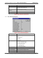
Figure 11: Insert > Master
For the Horner Smartstack CanOpen Master select COM-COM.
In this window select the required Master by clicking on it in the Available devices list and then click the
Add button or double click to put the Master in the Selected devices list. Confirm the selection with OK
and the Master will be inserted.
This example shows a CIF 50-COM with the Description Master. The description may be changed by
typing in this field.
4.4
Master Configuration
The Master specific configuration is carried out in the following window and subwindow.
Set the focus on the Master (left mouse click) and then select the Settings > Master Configuration
menu or double clicking on the symbol of the Master to be configured will open the following window:
Figure 7: Settings > Master Configuration
The following can be set in this Master Configuration window:
•
A (symbolic) Description of the Master
•
The window Master Settings can be opened
•
The window Global Settings can be opened
PAGE 25 of 111
EO 09-0009
© Horner APG.This drawing is the property of Horner APG. and shall not be disclosed or reproduced except as specifically authorised.
CH. 4 CANOPEN CONFIGURATION
CANopen Smartstack Manual
MAN0576-03-En
4.5
Replace Master
If a Master already exists in the configuration and should be replaced for another Master, first set the
focus on the Master (left mouse click) and then select the menu Edit > Replace. Or right mouse click on
the Master and select Replace in the window that appears:
Figure 8: Security question Replace Master
If Yes is selected a new window opens, where the existing Master may be replaced with the required
Master.
Figure 9: Edit > Replace Master
In this window select the Master required by clicking on it. By clicking the Add button this Master is
shown in the first position of the Selected devices list. With OK confirm the selection and the Master will
be replaced.
4.6
Insert Node
To insert a CANopen Node in the configuration, select the Insert > Node menu to open the selection
window, or click on the symbol:
Insert > Node
Figure 10: Insert > Node
PAGE 26 of 111
EO 09-0009
© Horner APG.This drawing is the property of Horner APG. and shall not be disclosed or reproduced except as specifically authorised.
CH. 4 CANOPEN CONFIGURATION
CANopen Smartstack Manual
MAN0576-03-En
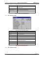
The mouse cursor changes automatically to the insert Node cursor. Click on the required position to
insert the new Node. A dialogue box appears where one or more Nodes may be selected for insertion.
Mousepointer for
Insert> Node
Figure 11: Mousepointer for Insert > Node
Figure 12: Insert > Node
The left list shows all the Node devices that are present in the EDS directory. A filter can be used to limit
the selection list via the Vendor and the Profile. lf a Node is selected then some additional information
about the Node is shown below the list box.
Double click or with the Add button, the selected Node appears in the Selected devices list. When a
new Node is chosen HSyCon always looks for the next free Node ID value and proposes it. By selecting
each Node the ID may be changed and it may be assigned a short description in the Description field
which will accept up to 32 characters of text.
It is possible to configure an available Node multiple times with different Node IDs. In CANopen the
Node address is called Node ID. The Node ID distinguishes the different Nodes from each other in the
network. It’s a unique number that must not be assigned twice. Therefore the entry in the field Node ID
must be equivalent to the real Node ID itself, otherwise the master will not be able to communicate with
the Node later when it tries to establish communication.
PAGE 27 of 111
EO 09-0009
© Horner APG.This drawing is the property of Horner APG. and shall not be disclosed or reproduced except as specifically authorised.
CH. 4 CANOPEN CONFIGURATION
4.7
CANopen Smartstack Manual
MAN0576-03-En
Node Configuration
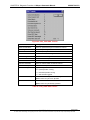
Left mouse click on the Node symbol and select the menu Settings > Node Configuration. Or double
click on the CANopen Node to open the Node Configuration window.
The Node specific configuration is carried out in this window. Here the PDO (Process Data Objects) and
their addresses in the process data image are assigned in the Smartstack Master. Please note, that the
addresses have to agree with the addresses in the PC application program.
Note 1 (Hilscher Master): The information about the Offset addresses relate to the addressing of the
data in the Master! The addresses don't relate to the addressing of the data in the Node. The Node
organizes its data addressing itself.
Note 2 (Hilscher Node): In case of a Hilscher Node (Slave) the In and Output bus data is taken directly
to and from the Dual-port memory. The Offset addresses relate to the Master.
Figure 13: Settings > Node Configuration
The following table shows the fields and elements of the Node Configuration window.
•
Node - The EDS file device name is shown in this field.
•
Description - contains a symbolic name for the Node.
•
File name - EDS file name.
PAGE 28 of 111
EO 09-0009
© Horner APG.This drawing is the property of Horner APG. and shall not be disclosed or reproduced except as specifically authorised.
CH. 4 CANOPEN CONFIGURATION
CANopen Smartstack Manual
MAN0576-03-En
•
Activate Node in actual configuration – Reserves process memory in the Master for this Node and
the Master makes a data exchange on the bus to this Node. If this setting is deactivated, the Master
reserves memory in the process data image for the Node, but no data exchange to this takes place.
•
Automatic COB-ID allocation in accordance with Profile 301 – Active in the basic setting. The
COB-ID is preset for a PDO depending upon the Node address and the PDO used. If this field is
deactivated, manual assignment of the COB-ID may be made. In order to reduce configuration effort
for simple networks a mandatory default identifier allocation scheme is defined, which is described
later. These identifiers are available in the Pre-operational state of a Node which works in
accordance with the Communication Profile 301 directly after initialization. These pre-defined
connection sets are used by HSyCon if automatic allocation is enabled. Then the COB-IDs in the
already configured PDO COB-ID column are not editable. If the automatic allocation is disabled the
COB-IDs may be edited in the range from 0 –2047.
Note: If the Automatic COB-ID allocation in accordance with Profile 301 is deactivated, HSyCon does not
check if a COB-ID was assigned more than once. The user must verify this before downloading the
configuration.
•
Device Profile and Device Type – Using the information of the Device Profile and the Device Type
the Master can read out the Object 1000H from the Node and compare it with this information when it
starts communication. If the Device Profile and the Device Type do not agree the Master reports a
parameterization error. Further information about the Device Profile and the Device Type may be
found in the section Device Profile and Device Type.
•
NodeID – The NodeID (address) is necessary for the addressing of the device on the bus and must
be unique. The COB-Id is determined from the NodeID.
•
Guard time – The Guard time is the supervision time of the Master related to the Node. Further
information about the Guard Time may be found in the section Node supervision - Nodeguarding
and Lifeguarding.
•
Life time factor – The Life time factor is information for the Node for the supervision of the Master.
Further information about the Life time factor may be found in the section Node supervision Nodeguarding and Lifeguarding
•
Emergency COB-ID – Information about the COB-ID of the Emergency telegram.
•
Nodeguard COB-ID - Information about the COB-ID of the Nodeguard telegram.
•
OK - Close the Node Configuration window and to accept the settings.
•
Cancel - Close the Node Configuration window and reject the settings.
•
Node BootUp - The NodeBootUp defines the start up behaviour of the Master with regard to each
individual Node and is described in section Node BootUp
•
OPC Objects - Information in the OPC Objects field relate to the symbols of the OPC server and the
SDO communication. Further information may be found in the manual for the OPC server.
•
Object Configuration - The object directory may be read from the EDS file and if necessary added
to the Node configuration.
•
Actual Node – Allows Changes to the Node configuration of another Node without leaving the
window.
•
PDO mapping method - Defines the procedure of the PDO mapping. Selection may be made
between DS301 V3 and DS301 V4. The difference between the methods are described.
PAGE 29 of 111
EO 09-0009
© Horner APG.This drawing is the property of Horner APG. and shall not be disclosed or reproduced except as specifically authorised.
CH. 4 CANOPEN CONFIGURATION
CANopen Smartstack Manual
MAN0576-03-En
•
Predefined Process Data Objects (PDOs) from the EDS file - Shows the list of the PDOs which
are given in the EDS file and which may be used in the configuration. Further information may be
found in the section Process Data Configuration - Selection of PDO.
•
Configured PDOs – Shows the PDOs which are used for the data exchange between Master and
Node. As well as the Offsets in the process data image the length of the PDO’s is indicated. Further
information may be found in the section Process Data Configuration - Selection of PDO.
•
Add to configured PDOs – Allows addition of a configured PDO to the Configured PDO list.
•
PDO Contents Mapping – With a PDO in the Configured PDOs list selected. Double click or click
on the PDO Contents Mapping button and the PDO transferred user data is shown, the combination
may be changed if necessary.
•
PDO Characteristics – Shows the transmission settings of the PDO. These may be adjusted if
necessary.
•
Define new Receive PDO – Allows a new Receive PDO to be added to the Configured PDOs list.
This is described in the section Creating Receive PDOs.
•
Define new Transmit PDO - Allows a new Transmit PDO to be added to the Configured PDOs list.
This is described in the section Creating Transmit PDOs
•
Delete configured PDO – Allows the deletion of a Configured PDO from the configured PDO list.
•
Symbolic Names – Relates to the symbols for the OPC server, for further information see the OPC
server manual.
4.8
Overview of Node Configuration
For the Node Configuration to transfer PDO data the following typical steps must be made.
Configuration step
Description
•
Device Profile and Device Type
Set or take over the value which is read from the EDS file.
•
Process Data Configuration
Select the PDO.
•
Process Data Configuration
Set the PDO transmission characteristics.
•
PDO Mapping
Take over the basic setting or adjust the PDO combination.
•
Node Bootup
Set startup behaviour.
•
Node supervision
Set Nodeguarding and/or Lifeguarding.
Table 6: Overview of Node Configuration
4.9
Device Profile and Device Type
Each CANopen Node has a mantatory Object 1000H, which must exist in the object directory. This object
is named Device Type. The Device Type also includes information about the Device Profile. The Master
reads the Object 1000H from the Node when starting up the CANopen bus and compares the entries,
which are made in the two available fields Device Profile and Device Type. If the Device Profile and the
Device Type do not agree, the Master reports a parameterization error and does not establish a process
data transfer to the Node. To get the real values of the Node, use the online function Online > Read
Object or click on the Node in Debug mode.
4.10
Process Data Configuration - Selection of PDO
PAGE 30 of 111
EO 09-0009
© Horner APG.This drawing is the property of Horner APG. and shall not be disclosed or reproduced except as specifically authorised.
CH. 4 CANOPEN CONFIGURATION
CANopen Smartstack Manual
MAN0576-03-En
The process data is transmitted via process data objects( PDOs), and assigned to the process data
image. CANopen distinguishes between receive and send PDOs.
Receive PDOs
Send PDOs
Data from the Master to the Node
Data from the Node (Slave) to the Master
Output data is processed by the Node.
Input data is generated by the Node (Slave).
Table 7: PDO - Send and Receive PDO
The data of the Node in the process data image of the Master are serviced for the application with the
configuration of the PDOs. The configuration window contains two tables. The upper table Predefined
Process Data Objects (PDOs) from EDS file shows all configurable PDOs, which are predefined in the
EDS file of the device. By double clicking on a table entry or via the Add to configured PDOs button the
entry is taken over to the Configured PDOs table. The columns of the Configured PDOs table have the
following meaning:
•
PDO name – The Rx and Tx PDO parameters are shown.
•
Symbolic Name - Here the symbolic name, which is used in case of OPC communication, is given.
PDO_1400 and PDO_1800 and continuous names are used as pre-set value. This may be
overwritten by the user.
•
COB-ID - In this column the CAN telegram identifier is shown. In the case of manual assignment the
telegram identifier of the CAN telegram which is transmitted with the PDO may be edited in the range
from 0 to 2047.
•
I Type and O Type – The specification IB stands for Input Byte and QB for Output Byte.
•
I Addr. and O Addr – The I Addr. (Input Address) and the O Addr. (Output Address) define the
address of the PDO data in the process data image, which is held in the Dual-port memory of the
Master. The range can be between 0 and 3583. The number of data bytes is shown under I Number
and O Number. The addresses may be assigned automatically by SyCon or manually by the user.
This is set in the menu Settings > Global Settings in the field Process Data Auto Addressing,
which is described in the section Global Settings. A screening for double addresses takes place
before the Download of Configuration and when the window Address Table is opened.
•
I Len. and O Len - Gives the length of the PDO in bytes and can be a max of eight. If the value 0 is
shown, the PDO does not include user data. The user data for this PDO may be set by the PDO
Mapping menu.
4.11
PDO Communication Parameter (PDO Characteristic)
Before a chosen PDO is moved into the lower window, the PDO characteristics window is opened
automatically. A PDO in CANopen can be configured such that it is transmitted in Event Driven mode or
Cyclic Transmission. Both kinds of transmission types can be synchronised to a special sychronization
message which is sent by the master in defined time intervals. Because of the different behaviour of a
transmit and receive PDO, two different windows will be open during the PDO insertion. The different
transmissions are distinguished in the so-called Transmission type value.
Synchronous means that the transmission of the PDO shall be related to the SYNC message that is sent
cyclically by the Master. Preferably the Nodes use the SYNC message as a trigger to output or actuate
based on the previous synchronous Receive-PDO respectively to update the data transmitted at the
following synchronous Transmit-PDO. Details of this mechanism depend on the device type and are
defined in the device profile.
Asynchronous means that the transmission of the PDO is not related to the SYNC message and can
happen at any time.
PAGE 31 of 111
EO 09-0009
© Horner APG.This drawing is the property of Horner APG. and shall not be disclosed or reproduced except as specifically authorised.
CH. 4 CANOPEN CONFIGURATION
4.12
CANopen Smartstack Manual
MAN0576-03-En
Receive PDO characteristics
Receive PDO are output data of the Master and are received by the Node.
Figure 14: Receive PDO Parameter
Transmission
Type
asynRTR Description
cycl. acycl. synchronous chronous
•
0
•
1..240
241..251
•
The telegram is transferred related to the SYNC, but
not periodically.
•
A value between 1 and 240 means that the PDO is
transferred synchronously and periodically and that the
value of the type of transmission shows the number of
SYNC telegrams between the two transferring PDOs.
res.
reserved
•
254
Type of transmission 254 means that the application
event is manufacturer dependent.
Table 8: PDO Communication Parameter > Transmission Types (Receive PDO)
The event control selection menu has two way to configure a Receive PDO for its transmission event.
•
Event-controlled, which configures the Master in such a way that the Master sends the Receive PDO
only if data has changed. This kind of the event control keeps the bus load low.
•
Cyclic transmission. Where the time is indicated in Node cycle intervals. A Node cycle interval is the
time the Master needs to test all configured PDOs in their states and to process them once. The
smallest cycle interval is about 300µsec.
4.13
Creating Receive PDOs
If further PDOs shall be used, which are not predefined in the table Predefined Process Data Objects
(PDOs) from EDS file, then they can be added with the function Define new Receive PDO.
PAGE 32 of 111
EO 09-0009
© Horner APG.This drawing is the property of Horner APG. and shall not be disclosed or reproduced except as specifically authorised.
CH. 4 CANOPEN CONFIGURATION
CANopen Smartstack Manual
MAN0576-03-En
Figure 15: Definite a new receive PDO
HSyCon suggests a free message number, which can be edited later in the PDO configuration window, if
the PDO was taken over.
4.14
Transmit PDO characteristics
Transmit PDOs are input data tot he Master and they are sent by the Node.
Figure 16: Transmit PDO Parameter
PAGE 33 of 111
EO 09-0009
© Horner APG.This drawing is the property of Horner APG. and shall not be disclosed or reproduced except as specifically authorised.
CH. 4 CANOPEN CONFIGURATION
Transmission
Type
MAN0576-03-En
asynRTR Description
cycl. acycl. synchronous chronous
0
X
1..240
CANopen Smartstack Manual
X
X
The telegram is transferred related to the SYNC, but not
periodically.
X
A value between 1 and 240 means that the PDO is
transferred synchronously and periodically and that the
value of the type of transmission indicates the number
of SYNC telegrams between the two transferring PDOs.
241..251
res.
252
X
reserved
X
The transmission types 252 and 253 mean that the
PDO is an event without immediate notification and it is
only transferred with remote transmission requirement.
With the type of transmission 252 the data are
immediately updated after receiving the SYNC
Telegram (however not sent).
X
The transmission types 252 and 253 mean that the
PDO is an event without immediate notification and it is
only transferred with remote transmission requirement.
With the type of transmission 253 the data are
immediately updated after receiving the SYNC
Telegram
253
X
254
X
The Transmission type 254 means that the application
event is manufacturer dependent.
255
X
The Transmission type 255 means that the application
event is defined in the respectively supported
equipment profile. The exact transmission mode
whether cyclically, event-controlled etc. can reread
there.
Table 9: PDO Communication Parameter > Transmission Types (Transmit PDO)
The event control selection menu has to two ways to configure a transmit PDO for its transmission event.
•
No remote request. The Master behaves completely passively to the PDO and is programmed only
for receiving. When the PDO is received is completely Node dependent here.
•
Remote request. Here the Master sends Remote-Telegrams in settable Node cycle intervals, which
instructs the Node to send its Transmit PDO to the Master upon receiving it.
4.15
Creating Transmit PDOs
If further PDOs shall be used, which are not predefined in the table Predefined Process Data Objects
(PDOs) from EDS file, this can be done with the function Define new Transmit PDO.
Figure 17: Definite a new Transmit PDO
HSyCon suggests a free message number, which can be edited later in the PDO configuration window, if
the PDO was taken over.
PAGE 34 of 111
EO 09-0009
© Horner APG.This drawing is the property of Horner APG. and shall not be disclosed or reproduced except as specifically authorised.
CH. 4 CANOPEN CONFIGURATION
4.16
CANopen Smartstack Manual
MAN0576-03-En
PDO Contents Mapping - Arrange a PDO
Some CANopen Nodes support PDO data mapping and dynamic distribution. This allows the user to
define the mapping of objects into a PDO. The mapping itself is always done by the Node internally after
is has received new RX-PDO or has to send new TX-PDO, so that the master can handle the input and
output PDOs from the Node completely transparently. This guarantees high speed data transfer and
execution in the view of the master. The Node’s mapping dictionary is only configured once during its
configuration phase.
A PDO can contain up to 8 bytes of process data. The combination of these individual process data
elements can be changed when the button Append Object is used. When a PDO was transferred from
the upper table to the Configured PDOs table, HSyCon automatically maps all found mappable process
data from the Nodes EDS file into this PDO.
Figure 18: PDO Contents Mapping
The picture above is an example for a TX-PDO mapping. The upper table shows all available objects
with their access rights which are declared in the node’s EDS file. A double click on one of these
transfers it into the lower table. This table contains the real mapped objects that shall be the content of
the PDO later in the process data exchange phase.
Note: Not all CANopen Nodes supports the PDO mapping feature!
PAGE 35 of 111
EO 09-0009
© Horner APG.This drawing is the property of Horner APG. and shall not be disclosed or reproduced except as specifically authorised.
CH. 4 CANOPEN CONFIGURATION
4.17
CANopen Smartstack Manual
MAN0576-03-En
Node BootUp
The Node BootUp defines the network startup behaviour of the Master to get a Node operative. There
are different states a Master can run through per Node. Each state is configurable and can be enabled
(activated) or disabled (deactivated) here. In the basic setting all states are activated.
Figure 19: Online > Node Configuration > Node BootUp
Node Reset - If enabled, the master sends the CANopen specific Node Reset Communication command.
Check Node Type and Profile - If enabled, the master will compare the contents of the mandatory Node
Object 1000H (device type) with the values configured within HSyCon. If the values are different, the
master will report a parameterisation error.
Configuration Guarding Protocol - A CANopen Master has two specific registers responsible for the
Node guarding protocol. If the item is enabled, the master will write the Guard Time and Life-Time factor
of the Node configuration into the corresponding objects of the Node during startup.
PAGE 36 of 111
EO 09-0009
© Horner APG.This drawing is the property of Horner APG. and shall not be disclosed or reproduced except as specifically authorised.
CH. 4 CANOPEN CONFIGURATION
CANopen Smartstack Manual
MAN0576-03-En
Configuration SYNC COB-ID - If the item is enabled, the master will write the SYNC COB-ID of the
configuration into the corresponding objects of the Node during startup.
Configuration EMCY COB-ID - If the item is enabled, the master will write the EMCY COB-ID of the
configuration into the corresponding objects of the Node during startup.
Configuration download of objects - To get a PDO communication to a Node working, the master has
to send all relevant configuration objects to the Node. For example the mapping table, the COB-ID a
PDO shall be sent through are covered here. If enabled, all these parameters and also the user specific
objects which are added manually in the Node object configuration window are written down to the Node
by the master.
Start Node - To reach the operational state in CANopen a Node has to get the CANopen specific Start
Node command. If enabled, the master will send the Start Node command to the Node at the end of the
boot-up procedure.
Initiate PDO data - This item selects if the installed PDOs shall be automatically written and read by the
master directly after the startup. This ensures that the latest data is exchanged between the Master and
Slave.
4.18
Node supervision - Nodeguarding and Lifeguarding
The Guard time and Life time factor settings serve the supervision of the Node and the supervision of
the Master in the view of the Node. Once communication is established to the Node, the Master will poll
the Node in Guard time multiplied by Life time factor time intervals with special guard telegrams to
check if it is still present in the network or not. The Node supervises if the Master has done a guard
polling during the configured time interval to check if the Master is still present. If one of these values is
configured to 0, then the supervision is disabled in the Master as well as in the Node. The Node itself will
start with the Node guarding when the first remote-transmit-request from the Master for its guarding
identifier is received. The Master will start the Node guarding after it has initialized all the communication
objects necessary for the Node. If the Node guarding fails during runtime, the Master will reset the
communication to the specific Node and restarts its initialization.
Note: If the Node does not support the Nodeguarding, the Master cannot recognize that the Node failed.
4.19
Object Configuration
The most important part of a CANopen device is its object directory. The object directory is essentially a
grouping of objects accessible via the network in an ordered predefined fashion. Each object within the
directory is addressed using a 16-bit index. The Device profiles of CANopen define the name, the
meaning, the value range and data type of the Service Data Objects (SDO). With Service Data
Messages the contents of an object and its subindex can be changed. This is necessary to set up the
behaviour of a CANopen Node in the required manner.
To get access to the SDO configuration press the Object Configuration button. The window shown
below will appear and shows all supported objects read from the EDS file of the Node in the upper table.
If some PDOs have already been inserted they will be shown in the lower table too.
HSyCon places some objects in this table automatically when a PDO in the Node Configuration window
is inserted. These values can not be edited.
PAGE 37 of 111
EO 09-0009
© Horner APG.This drawing is the property of Horner APG. and shall not be disclosed or reproduced except as specifically authorised.
CH. 4 CANOPEN CONFIGURATION
CANopen Smartstack Manual
MAN0576-03-En
Figure 20: Online > Node Configuration > Object Configuration
4.20
OPC Objects
Symbols for the OPC communication can be entered via SDO telegrams from this window. Objects may
be selected from the list provided. Further information may be found in the OPC Server manual.
4.21
OPC User Defined Objects
Symbols for the OPC communication can be entered via SDO telegrams from this window. Objects can
be entered by the user. Further information may be found in the OPC Server manual.
4.22
Replace Node
If a Node already exists in the configuration and should be replaced with another Node, first set the focus
on the Node (left mouse click) and then choose the menu Edit > Replace. Or right mouse click on the
Node and select Replace in the menu that opens. In the opened window the question appears asking if
the Node should be replaced.
Figure 21: Security question Replace Device
PAGE 38 of 111
EO 09-0009
© Horner APG.This drawing is the property of Horner APG. and shall not be disclosed or reproduced except as specifically authorised.
CH. 4 CANOPEN CONFIGURATION
CANopen Smartstack Manual
MAN0576-03-En
The Yes button opens a new window, where the new Node may be selected.
Figure 22: Edit > Replace Node
In this window select the required Node by clicking on it. By clicking the Add button the Node is shown in
the Selected devices list. With OK confirm the selection and the Node will be replaced.
PAGE 39 of 111
EO 09-0009
© Horner APG.This drawing is the property of Horner APG. and shall not be disclosed or reproduced except as specifically authorised.
CH. 5: SETTINGS
CANopen Smartstack Manual
MAN0576-03-En
CHAPTER 5: SETTINGS
5.1
Device Assignment
The Device Assignment setting determines how the System Configurator communicates with the device.
This is set in the device arrangement via the menu Settings > Device Assignment. The following
possibilities are available:
CIF Device Driver
CIF Serial Driver
CIF TCP/IP Driver
CIF Device Driver:
•
Not supported do not choose this driver.
CIF Serial Driver:
•
CIF Serial Driver: The HSystem Configurator communicates with the SmartStack device over a serial
connection. In this case a COM interface of the PC must be connected via a cable (straight) with the
diagnostic interface of the SmartStack device. The cable is standard Horner Programming cable.
CIF TCP/IP Driver:
•
Not supported do not choose this driver.
5.2
COM Serial Driver
The serial driver supports COM1 to COM 4, in order to communicate via the diagnostic interface with the
device. The Device is selected via Settings > Device Assignment.
Figure 23: Driver selection – CIF Serial Driver
Choose the CIF Serial Driver and then OK, in order to select the CIF Serial Driver. The connection must
first be established using the switching surface Connect COM1 or Connect COM2 or Connect COM3 or
Connect COM4. They can be used depending on which COM interfaces are installed and free on the
PC.
PAGE 41 of 111
EO 09-0009
© Horner APG.This drawing is the property of Horner APG. and shall not be disclosed or reproduced except as specifically authorised.
CH. 5: SETTINGS
CANopen Smartstack Manual
MAN0576-03-En
The System Configurator sends a request to the corresponding COM interface and polls the Firmware of
the device. A display of the Firmware will indicate when a device is connected. In the other case, a
Timeout error (-51) appears, which will state that no device is connected.
Figure 24: CIF Serial Driver – Device Assignment
The error number – 20 indicates that this COM interface is not available or already in use.
5.3
Bus Parameters
The Bus Parameters are the foundations of a functioning data exchange. This section contains
information for setting the Bus Parameters as well as the descriptions of the individual parameters.
In these windows the basic settings for the CANopen network are done. Mainly, this concerns the setting
of the Baudrate.
Attention: Check that all CANopen Nodes support the selected Baud rate.
Basic rule: The Baud rate must be the same for all devices. The Node address on the other hand must
differ from Node to Node. The Master itself does not have a Node address.
PAGE 42 of 111
EO 09-0009
© Horner APG.This drawing is the property of Horner APG. and shall not be disclosed or reproduced except as specifically authorised.
CH. 5: SETTINGS
CANopen Smartstack Manual
MAN0576-03-En
Figure 25: Settings > Bus Parameter
•
SYNC COB-ID and SYNC-Message – The cycle time of the SYNC-Message and its message number
COB-ID must to be set. The default value is 128. As soon as a participant with synchronized PDO
transfer is configured, the SYNC message is sent in the configured cycle period frame from the
Master.
•
Auto clear mode OFF – The Auto Clear feature defines the behaviour of the Master if the
communication is interrupted to a Node. If the flag Auto clear mode ON is activated, the Master will
also stop the communication to all further Nodes which were still responding and active. If the flag
Auto clear mode OFF is activated, then a lost communication contact to one Node has no influence
on the communication channel of the still present ones. For all the error affected Nodes the master
tries to re-establish communication.
•
Enable Global Start Node – Once all the desired nodes have been configured the Master sends a
Global Start Node command to start all the nodes synchronously.
•
5.4
5.5
CANopen Master
Master Settings
To enter the CANopen Master settings, select the menu Settings > Master Settings or right mouse
button click on the corresponding Master symbol and select Master Settings from the list which opens
up.
The CANopen Master Settings contain parameters that determine the behaviour of the Master device as
well as the user interface. These settings are only valid for SmartStack devices and are included in the
download of the configuration.
PAGE 43 of 111
EO 09-0009
© Horner APG.This drawing is the property of Horner APG. and shall not be disclosed or reproduced except as specifically authorised.
CH. 5: SETTINGS
CANopen Smartstack Manual
MAN0576-03-En
Figure 26: Settings > CANopen Master Settings
•
Startup behaviour after system initialisation – Always select Automatic release of the communication
by the device, this allows the Master device to start the data exchange on the Bus once the
initialization is complete. If Controlled release of communication by the application program has
been set, the application program must activate the data exchange at the Bus.
•
User program monitoring - The Watchdog time determines how long the device waits for a triggering
of the software watchdog by the application program until it sets the outputs of the Slave devices to 0.
This behaviour must be activated by the user program and does not start automatically, always set
this to 0mS.
Note: The Watchdog is not a special CANopen function, but an often needed feature in interaction with a
SoftPLC.
•
Addressing mode – The addressing mode of the process data image determines how the addresses
(Offsets) of the process data are interpreted. Either of the addressing modes Byte addresses or
Word addresses are possible.
•
Storage format (word module) – The storage format determines how the data is interpreted and
stored in the process image. This allows the connection of nodes with different Endian data.
•
Handshake of the process data – Always use Buffered, host controlled. This parameter defines how
data is exchanged with the OCS / TIU and is fixed in these systems.
•
Hardware parameter – The size of the dual-port memory of the hardware can be selected. The
parameter will enlarge or reduce the possible value ranges for the I/O offsets. In the CANopen
Master the dual-port memory size is 8K, whereby 7K is process data.
PAGE 44 of 111
EO 09-0009
© Horner APG.This drawing is the property of Horner APG. and shall not be disclosed or reproduced except as specifically authorised.
CH. 5: SETTINGS
5.6
CANopen Smartstack Manual
MAN0576-03-En
Addressing Mode
The addresses in the configuration of the Nodes define the starting point of the data in the process image.
This can work in a Word or Byte oriented method by means of the Addressing mode parameter.
Addresses
Byte addresses
Meaning
The process image has a Byte structure and each Byte has its own address.
Word addresses The process image has a Word structure and each Word has its own address.
Table 10: Addressing Mode
The following table is meant to clarify the method of addressing:
Byte addressing
Byte 0
I/QB 0
Byte 1
I/QB 1
Byte 2
I/QB 2
Byte 3
I/QB 3
Byte 4
I/QB 4
Byte 5
I/QB 5
Word addressing
I/QW 0
Word 0
I/QB 0
I/QW 0
I/QW 2
Word 1
I/QB 1
I/QW 1
I/QW 4
Word 2
I/QB 2
I/QW 2
-
Table 11: Image of the method of addressing for input and Output.
5.7
Global Settings
Set the focus on the Master (left mouse click) and select the menu Settings > Global Settings. Or
click on the symbol of the Master device with the right mouse key to select the menu Master
Configuration and then click the button Global Settings.
Figure 27: Settings > Global Settings
•
Process Data Auto Addressing – Allows selection of Automatically assigned addressing or Manually
assigned addressing during configuration. In Auto addressing the addresses will be allocated
beginning with 0 and incremented in accordance with the entry sequence of the Slaves before
downloading and can be viewed and checked in the menu View > Address Table. In Manual
Addressing the address 0 is shown in the I Addr or O Addr and must be overwritten by the user.
PAGE 45 of 111
EO 09-0009
© Horner APG.This drawing is the property of Horner APG. and shall not be disclosed or reproduced except as specifically authorised.
CH. 5: SETTINGS
CANopen Smartstack Manual
MAN0576-03-En
•
COB-ID Allocation during PDO insertion – The CANopen specification provides that the message
number (COB-ID) of a PDO is given relative to the Node address according to a fixed definition. It is
called the Pre-Defined Connection Set.
•
Automatic Allocation in accordance with Profile 301 - If this option is selected, alteration of the
message number of the PDOs is not possible and its assignment takes place automatically by the
CANopen profile 301.
•
Manual Allocation in range 0-2047 - If this menu option is selected, assignment of the message
number of the PDOs is possible and can take place in the context of the 2048 (11 bit) different
possible CAN-Identifiers.
5.8
CANopen Node
5.9
Node Settings
The CANopen Node Settings contain parameters that define the behaviour of the device at the user
interface, which does not belong to the CANopen Node configuration. This menu is applicable only to
SmartStack devices. These settings are transferred with the download of the CANopen configuration to
the device.
To open the CANopen Node Settings menu, choose the Node and then open the window in the Settings
> Node Settings menu. Or right mouse click on the symbol of the Hilscher Node device and then select
Node Settings.
Figure 28: Settings > CANopen Node Settings
•
User program monitoring - The watchdog time appoints how long the device will wait for a user trigger
of the watchdog, until it resets all outputs to zero. This must be set to 0mS.
.
•
Handshake of the process data – Must be set to Buffered, host controlled.
•
Startup behaviour after system initialisation – Must be set to Automatic release of the communication
by the device.
PAGE 46 of 111
EO 09-0009
© Horner APG.This drawing is the property of Horner APG. and shall not be disclosed or reproduced except as specifically authorised.
CH. 5: SETTINGS
5.10
CANopen Smartstack Manual
MAN0576-03-En
Project Information
The user project information can be typed into the Settings > Project Information menu. The entry may
be read anytime by re-opening the menu.
Figure 29: Settings > Project Information
Click the OK button to save the Project Information.
5.11
Path
When the Settings > Path menu is selected, the search path for EDS files is displayed.
Figure 30: Settings > Path
Click the button OK to read in all the EDS files.
5.12
Languages
Choose the Settings > Language menu and the following window opens:
PAGE 47 of 111
EO 09-0009
© Horner APG.This drawing is the property of Horner APG. and shall not be disclosed or reproduced except as specifically authorised.
CH. 5: SETTINGS
CANopen Smartstack Manual
MAN0576-03-En
Figure 31: Settings > Language
Select the desired language and confirm the entry with the OK button. A message appears that the
System Configurator must be started again in order to activate the selected language. Upon restarting
the System Configurator, the language will have changed to the one selected.
Note: Not all languages are available for all fieldbuses!
5.13
Start Options
Upon activating the Settings > Start... menu in the network mode, the following dialog will appear. Here
it is possible to set the various starting options or modes. Some are only of importance for the OPCServer operation.
Note: The point of menu start options appears only in the selection settings, if the network view is
opened.
PAGE 48 of 111
EO 09-0009
© Horner APG.This drawing is the property of Horner APG. and shall not be disclosed or reproduced except as specifically authorised.
CH. 5: SETTINGS
CANopen Smartstack Manual
MAN0576-03-En
Figure 32: Settings > Start Options
•
Simulation mode ON/OFF - Only valid for the OPC Server.
•
Start SyCon hidden if started via OPC - Only valid for the OPC Server.
•
Start SyCon next time with last Configuration – Restores the last configuration when next started.
•
Logic Network View visible - Allows the possibility of diverting to the network mode without having to
install the SyCon with OPC. It is also possible to use the Watch List from the network mode.
•
Fast start ON/OFF - Only valid for the OPC Server.
•
TAG tracing ON/OFF - Only valid for the OPC Server.
•
OPC tracing ON/OFF - Only valid for the OPC Server.
Only valid for the OPC Server.
•
Auto connect ON/OFF – Allows automatic connection to the module without having to use the Device
Allocation menu.
•
Start with multiple configurations – Allows the possibility to start SyCon with up to four configurations
simultaneously. The paths are shown in the window and are configurable.
PAGE 49 of 111
EO 09-0009
© Horner APG.This drawing is the property of Horner APG. and shall not be disclosed or reproduced except as specifically authorised.
CH. 6: ONLINE FUNCTIONS
CANopen Smartstack Manual
MAN0576-03-En
CHAPTER 6: ONLINE FUNCTIONS
6.1
Introduction
In this section all the functions that directly influence SmartStack CANopen devices, e.g. COM-COM and
COM-COS are presented.
Note: This also permits interruption of the communication or that input and output can be switched ON or
OFF.
6.2
Downloading the Configuration
Chose the desired device by a left mouse click on the symbol of the device. In order to release the
configuration and network access, a transfer (Download) to the COM device must be carried out on the
Online > Download menu. A warning will appear that the communication on the CANopen will be
interrupted. This warning must be confirmed.
Figure 33: Security question before Download
Attention: The download overwrites the configuration in the device and the communication with the
connected devices is interrupted.
Figure 34: Online > Download
PAGE 50 of 111
EO 09-0009
© Horner APG.This drawing is the property of Horner APG. and shall not be disclosed or reproduced except as specifically authorised.
CH. 6: ONLINE FUNCTIONS
CANopen Smartstack Manual
MAN0576-03-En
Before the Download is executed, the configuration is checked by the Configurator. The most common
cause of error is overlapping of addresses in the process data image. This can be checked by calling up
the address table with the View > Address Table menu. If the assignment of addresses in the process
data image should be carried out automatically, then the Auto Addressing button in the Master
Configuration window must be activated.
The configuration is transferred to the selected device and is stored in non-volatile FLASH memory so
that the configuration is available when the voltage supply is switched off and on again.
After the download, the device carries out an internal restart and begins with the communication if in
CANopen Master Settings the Automatic Release of Communication by the Device menu point has
been set.
6.3
Firmware Download
If a firmware download is to be carried out, proceed as follows: Select the desired device to be loaded.
Then, call up the Online > Firmware Download menu. Select the new Firmware and retrieve it with
Download to the device. The Firmware is now retrieved.
Figure 35: Online > Firmware Download
6.4
Firmware / Reset
Choose the desired device with a left mouse click on the symbol of the device. Then the Online >
Firmware / Reset menu must be called up and the name and the version of the Firmware are displayed.
PAGE 51 of 111
EO 09-0009
© Horner APG.This drawing is the property of Horner APG. and shall not be disclosed or reproduced except as specifically authorised.
CH. 6: ONLINE FUNCTIONS
CANopen Smartstack Manual
MAN0576-03-En
Figure 36: Online > Firmware / Reset
The device is reset by the Reset button.
Select the desired device with a left mouse click on the symbol of the device. Then select the Online >
Device Info menu in order to obtain further information on the selected device. The manufacturer date,
the device number and the serial number of the device is retrieved and shown.
Figure 37: Online > Device Info
6.5
Start/Stop Communication
The communication between CANopen Master and CANopen Node can be manually started or stopped.
Select the desired device with a left mouse click on the symbol of the device. Then select the Online >
Communication start or Online > Communication stop menu.
6.6
Diagnostic Functions
The following table shows diagnostic functions and their use with
•
SmartStack CANopen Master devices
•
SmartStack CANopen Nodes (Slaves).
Diagnostic Function
Description
For SS
For SS
Master
Nodes
devices
Live List
Determine, which devices are connected to the Hilscher
CANopen Master device.
Yes
No
Debugmode (CANopen)
Determine, to which CANopen Nodes the Hilscher CANopen
Master has communication
Yes
No
Global State Field
Status information of the Hilscher CANopen Master
Yes
No
Yes
Yes
Extended Device Diagnostic Statistic information and status information from the Hilscher
CANopen device
Table 12: Overview Diagnostic Functions
PAGE 52 of 111
EO 09-0009
© Horner APG.This drawing is the property of Horner APG. and shall not be disclosed or reproduced except as specifically authorised.
CH. 6: ONLINE FUNCTIONS
6.7
CANopen Smartstack Manual
MAN0576-03-En
Live List
Select the desired device with a left mouse click on the device symbol. Then select the Online > Live
List menu and obtain an overview of all active devices on the CANopen network.
Figure 38: Online > Live List
Generally all devices are displayed in grey. Any Nodes detected on the bus are represented in black on
the appropriate Node address.
6.8
Debugmode (CANopen)
Select the menu item Online > Start Debug Mode. The System Configurator cyclically interrogates the
status of the network communication from the COM and the individual conditions of the Nodes. To end
the Debug Mode select the menu Online > Stop Debug Mode.
6.9
The Debugwindow
When the debug session is started the configuration window changes to the debug window. T he devices
and the line between them are displayed in green or red colour depending on the established network
communication.
PAGE 53 of 111
EO 09-0009
© Horner APG.This drawing is the property of Horner APG. and shall not be disclosed or reproduced except as specifically authorised.
CH. 6: ONLINE FUNCTIONS
CANopen Smartstack Manual
MAN0576-03-En
Figure 39: The Debugwindow
If diagnostic information is available for a specific device, next to the device Icon the text Diag appears in
red. To get further device specific diagnostic information doubleclick on the device itself or set the focus
to the device and select Online > Device Diagnostic.
Note: The CANopen Master (NMT-Master) can only recognize that the Node has failed if the CANopen
Node supports Nodeguarding.
The Master icon has the
6.10
sign to show stop mode and in run mode has the sign
.
CANopen Node specific Diagnostic
If the device indicates diagnostic information (Diag appears beside node). This information is displayed
in detail by clicking with the mouse on the corresponding device in debug mode. To activate the debug
mode mark the Master with a left mouse click and select the menu Online > Start Debug Mode. Now
set the focus on the Node (left mouse click) and select the menu Online > Device Diagnostic to show
the CANopen Device Diagnostic. To end the Debug Mode mark the Master again and select the menu
Online > Stop Debug Mode.
PAGE 54 of 111
EO 09-0009
© Horner APG.This drawing is the property of Horner APG. and shall not be disclosed or reproduced except as specifically authorised.
CH. 6: ONLINE FUNCTIONS
CANopen Smartstack Manual
MAN0576-03-En
Figure 40: Online > Device Diagnostic (CANopen Standard Diagnostic)
The individual bits in the Device Diagnostic and their meaning:
No Response - The Node is configured but is not present on the network. Check the physical connection
between the Master and Node. Compare the selected baudrate of the Node with the baudrate of the
Master. Check the Node address.
Emergency buffer overflow - CANopen defines a special reserved emergency channel for each Node
with high priority to give the ability to report emergency messages triggered by the occurrence of a device
internal fatal error situation. The emergency messages of each Node are saved in an internal buffer on
the Master. The buffer will be cleared when HSyCon reads it out and shows the telegrams in the lower
Emergency telegrams window. If the buffer overflows telegrams will be lost. In this case a buffer
overflow event is reported. Emergency error codes are defined by the CANopen Communication Profile.
Emergency telegrams in the lower table can be interpreted textually by clicking on the Interpret
Telegrams button.
Parameterization fault - The Master compares the configured Device Profile and the corresponding
Device Type value of the Node Configuration window with the real physically present ones in the Node
by reading out the Node object 1000H. If the Master detects differences between the values it will report
the Parameterization Fault. The actual Node value read by the master is shown beside the Device
profile number Object 1000H and Additional information Object 1000H entry.
Node guarding active - As soon as the master has finished the configuration phase of the Node it will
start the cyclic Node guarding mechanism and set the Node guarding active flag. The Node guarding will
only be active if the Guard time and the Life time factor in the Node Configuration window are non zero.
Internal fault - The internal fault indication serves to report master internal fatal error situations. If it is
reported then call Tech support or the distributer from whom the module was purchased.
Deactivated - This bit is automatically set by the master, if the Node state was configured to Deactivate
Node in actual configuration in the Node Configuration window.
PAGE 55 of 111
EO 09-0009
© Horner APG.This drawing is the property of Horner APG. and shall not be disclosed or reproduced except as specifically authorised.
CH. 6: ONLINE FUNCTIONS
6.11
CANopen Smartstack Manual
MAN0576-03-En
Emergency Telegrams
Emergency telegrams are sent by the Node when an internal event occurs. The CANopen Master can
buffer 5 Emergency telegrams maximum per node.
Figure 41: Online > Device Diagnostic > Interpretation of emergency telegrams
A table with the Error Codes is described in section Emergency Telegram Error Codes.
Note: The table Emergency Error Codes is a general list. For the exact meaning it is referred to the
manual of the Node manufacturer.
6.12
Global State Field
Menu option Online > Global State Field opens a window in which statistics about the bus status and
connected devices are shown.
PAGE 56 of 111
EO 09-0009
© Horner APG.This drawing is the property of Horner APG. and shall not be disclosed or reproduced except as specifically authorised.
CH. 6: ONLINE FUNCTIONS
CANopen Smartstack Manual
MAN0576-03-En
Figure 42: Online > Global State Field
The first row displays the main status of the Master. OPERATE, STOP or OFFLINE are the possible
states. The next row displays individual bus errors. A pending error is displayed with a red field. The
meaning of the individual abbreviations is described in the following:
Bus error
Meaning
•
TOUT
Timeout Error
•
NRDY
HOST-NOT-READY-NOTIFICATION
shows, if the application program is ready or not. If this bit is set the application
program is not ready to communicate.
•
EVE
EVENT-ERROR
the CAN chip has detected transmission errors. The number of detected events are
counted in the bus off reports and the error warning limit counter. The bit will be set
when the first event was detected and will not be deleted any more.
•
FAT
FATAL-ERROR
because of heavy bus error, no further bus communication is possible.
•
NEXC
NON-EXCHANGE-ERROR
At least one Node has not reached the data exchange state and no process data are
exchanged with it.
•
ACLR
AUTO-CLEAR-ERROR
device stopped the communication to all Nodes and reached the auto-clear end state.
•
CTRL
CONTROL-ERROR
a parameterisation error has occurred.
Table 13: Meaning of collective status bits in the Global State Field
PAGE 57 of 111
EO 09-0009
© Horner APG.This drawing is the property of Horner APG. and shall not be disclosed or reproduced except as specifically authorised.
CH. 6: ONLINE FUNCTIONS
CANopen Smartstack Manual
MAN0576-03-En
Further contents are given:
Collective online error location and corresponding error gives the address of the incorrect station and
the lining up error in plain text.
Statistic bus information gives the number of detected bus short-circuits and rejected telegrams.
Device specific status bits - Parameterized Devices, Activated Devices and Devices with
Diagnostic are shown by clicking on the button. The activated addresses are coloured numbers, doubleclick on a highlighted station address to see the diagnostic data.
6.13
Extended Device Diagnostic
The Extended Device Diagnostic helps to find Bus and configuration errors when the HSyCon menu
functions are of no further help. Choose the required device by clicking on the device symbol with the left
mouse button. Then select the Online > Extended Device Diagnostic menu.
This menu opens a list of diagnostic structures. These contain online counters, status and parameters:
Figure 43: Online > Extended Device Diagnostic
6.14
User Data Transfer
The following table showstest functions with user data transfer and the use for
•
SmartStack CANopen Master devices
•
SmartStack CANopen Nodes
User data transfer function
Usage
Use with SS
CANopen
Use with SS
CANopen
Master
Slave
I/O-Monitor
Read input data and set output data. (cyclic I/O data
exchange)
Yes
Yes
Error! Reference source not
found.
Read input data and set output data. (cyclic I/O data
exchange)
Yes
No
Read Objects (SDO Upload)
Read objects (SDO Upload)
Yes
No
Write Object (SDO Download)
Write objects (SDO Download)
Yes
No
Table 14: Overview User Data Transfer
PAGE 58 of 111
EO 09-0009
© Horner APG.This drawing is the property of Horner APG. and shall not be disclosed or reproduced except as specifically authorised.
CH. 6: ONLINE FUNCTIONS
6.15
CANopen Smartstack Manual
MAN0576-03-En
I/O-Monitor
This is an easy way of viewing and changing the first 32 bytes of the process data image. The I/O
Monitor is called up with the menu Online > I/O Monitor.
Figure 44: Online > I/O-Monitor
DEC/HEX - Converts the display of the input data. The output data is always in decimal form.
Update - Enter the output value and then press.
The first 32 input and output bytes of the process data is shown, even when these bytes have not been
occupied by the configuration. The display is always in a Byte manner.
PAGE 59 of 111
EO 09-0009
© Horner APG.This drawing is the property of Horner APG. and shall not be disclosed or reproduced except as specifically authorised.
CH. 6: ONLINE FUNCTIONS
6.16
CANopen Smartstack Manual
MAN0576-03-En
Read Objects (SDO Upload)
Allows the execution of the CANopen services read object and write object based on the current
configuration. Select the required device by clicking with the left mouse button on the Node symbol.
Then select the menu Online Read Object or Online > Write Object.
Figure 45: Online > Read Object
6.17
Write Object (SDO Download)
Allows the execution of the CANopen services read object and write object based on the current
configuration. Select the required device by clicking with the left mouse button on the Node symbol.
Then select the menu Online Read Object or Online > Write Object.
Figure 46: Online > Write Object
Objects in CANopen are addresses in the manner Object-Index and Sub-Index. Both values must be
specified in the selected window. Press Read or Write button to start the action. HSyCon informs about
the success or failure of the action.
6.18
Message Monitor
The Message Monitor permits access to the Mailbox of the COM. The usage of the Message Monitor
assumes advanced knowledge on the part of the user.
First the Hilscher device must be chosen with a left mouse click on the symbol of the Hilscher device.
Then call up the Online > Message Monitor menu.
PAGE 60 of 111
EO 09-0009
© Horner APG.This drawing is the property of Horner APG. and shall not be disclosed or reproduced except as specifically authorised.
CH. 6: ONLINE FUNCTIONS
CANopen Smartstack Manual
MAN0576-03-En
Figure 47: Online > Message Monitor
A Message can be saved and retrieved and has the file suffix *.MSG.
File > New: closes the window
File > Open: opens a Message (Message can be retrieved)
File > Save or File > Save As: saves a Message
File > Exit: ends the Message Monitor and returns to the SyCon.
6.19
Message Monitor for Using LSS/LMT
LSS/LMT services can be used to set the baud rate and the Node address for some Nodes.
The LSS/LMT Master sends telegrams to the LSS/LMT Slave with CAN telegram identifier 2021 (07E5H).
The LSS/LMT Slave replies to the LSS/LMT Master with the CAN telegram identifier 2020 (07E4H).
Note: Only one Node may be coupled to the Master at a time.
The baud rate of the SmartStack CANopen Master must be set equal to the baud rate of the Node.
PAGE 61 of 111
EO 09-0009
© Horner APG.This drawing is the property of Horner APG. and shall not be disclosed or reproduced except as specifically authorised.
CH. 6: ONLINE FUNCTIONS
CANopen Smartstack Manual
MAN0576-03-En
Then the receive filter must be set to the CAN telegram identifier 2020.
Message for Setting the Receive Filter CAN (Layer 2)
Message Header
Rx = 3 (fixed)
Tx = 255
Ln = (is calculated)
Nr = 0...255
A=0
F=0
B = 82
E=0
Send Data
Meaning for CAN
Range of value
CAN Receive ID Part 1 (LSB)
228
CAN Receive ID Part 2 (MSB)
7
Table 15: Message Monitor for LSS/LMT > Setting the Receive Filter
Figure 48: Message Monitor for LSS/LMT > Set the Receive Filter
PAGE 62 of 111
EO 09-0009
© Horner APG.This drawing is the property of Horner APG. and shall not be disclosed or reproduced except as specifically authorised.
CH. 6: ONLINE FUNCTIONS
CANopen Smartstack Manual
MAN0576-03-En
Switch in configuration mode
Message for Sending via CAN (Layer 2)
Message Header
Rx = 3 (fixed)
Tx = 255
Ln = (is calculated)
Nr = 0...255
A=0
F=0
B = 84
E=0
Send Data
Meaning for CAN
Range of value
CAN Receive ID Part 1 (LSB)
252
CAN Receive ID Part 2 (MSB)
162
Send data 1: Mode Global Service
4
Send data 2: Config Mode
1
Table 16: Message Monitor LSS/LMT (1) > Switch Configuration Mode on
Figure 49: Message Monitor LSS/LMT (1) > Switch Configuration Mode on
PAGE 63 of 111
EO 09-0009
© Horner APG.This drawing is the property of Horner APG. and shall not be disclosed or reproduced except as specifically authorised.
CH. 6: ONLINE FUNCTIONS
CANopen Smartstack Manual
MAN0576-03-En
Set the Node Address
Message for Sending via CAN (Layer 2)
Message Header
Rx = 3 (fixed)
Tx = 255
Ln = (is calculated)
Nr = 0...255
A=0
F=0
B = 84
E=0
Send Data
Meaning for CAN
Range of value
CAN Receive ID Part 1 (LSB)
252
CAN Receive ID Part 2 (MSB)
162
Send data 1: Set Node ID
17
Send data 2: Node Address
1...127
Table 17: Message Monitor LSS/LMT (2) > Set Node Address
Figure 50: Message Monitor LSS/LMT (2) > Set Node Address
PAGE 64 of 111
EO 09-0009
© Horner APG.This drawing is the property of Horner APG. and shall not be disclosed or reproduced except as specifically authorised.
CH. 6: ONLINE FUNCTIONS
CANopen Smartstack Manual
MAN0576-03-En
Set Baud Rate
Message for Sending via CAN (Layer 2)
Message Header
Rx = 3 (fixed)
Tx = 255
Ln = (is calculated)
Nr = 0...255
A=0
F=0
B = 84
E=0
Send Data
Meaning for CAN
Range of value
CAN Receive ID Part 1 (LSB)
252
CAN Receive ID Part 2 (MSB)
163
Send data 1: Set Baud Rate
19
Send data 2: Table
0 (Standard Table)
128...255
Send data 3: Baud Rate
In case of table 0:
0 = 1 Mbit/s
1 = 800 kbit/s
2 = 500 kbit/s
3 = 250 kbit/s
4 = 125 kbit/s
5 = 50 kbit/s
6 = 20 kbit/s
Table 18: Message Monitor LSS/LMT (3) > Set Baud Rate
PAGE 65 of 111
EO 09-0009
© Horner APG.This drawing is the property of Horner APG. and shall not be disclosed or reproduced except as specifically authorised.
CH. 6: ONLINE FUNCTIONS
CANopen Smartstack Manual
MAN0576-03-En
Figure 51: Message Monitor LSS/LMT (3) > Set Baud Rate
PAGE 66 of 111
EO 09-0009
© Horner APG.This drawing is the property of Horner APG. and shall not be disclosed or reproduced except as specifically authorised.
CH. 6: ONLINE FUNCTIONS
CANopen Smartstack Manual
MAN0576-03-En
Save Configuration
Message for Sending via CAN (Layer 2)
Message Header
Rx = 3 (fixed)
Tx = 255
Ln = (is calculated)
Nr = 0...255
A=0
F=0
B = 84
E=0
Send Data
Meaning for CAN
Range of value
CAN Send ID Part 1
252
CAN Send ID Part 2
161
Send data 1: Save Configuration
23
Table 19: Message Monitor LSS/LMT (4) > Save Configuration
Figure 52: Message Monitor LSS/LMT (4) > Save Configuration
PAGE 67 of 111
EO 09-0009
© Horner APG.This drawing is the property of Horner APG. and shall not be disclosed or reproduced except as specifically authorised.
CH. 6: ONLINE FUNCTIONS
CANopen Smartstack Manual
MAN0576-03-En
Switch in Operating Mode
Message for Sending via CAN (Layer 2)
Message Header
Rx = 3 (fixed)
Tx = 255
Ln = (is calculated)
Nr = 0...255
A=0
F=0
B = 84
E=0
Send Data
Meaning for CAN
Range of value
CAN Send ID Part 1
252
CAN Send ID Part 2
161
Send data 1: Save Configuration
23
Table 20: Message Monitor LSS/LMT (5) > Switch in Operating Mode
Figure 53: Message Monitor LSS/LMT (5) > Switch in Operating Mode
PAGE 68 of 111
EO 09-0009
© Horner APG.This drawing is the property of Horner APG. and shall not be disclosed or reproduced except as specifically authorised.
CH. 6: ONLINE FUNCTIONS
6.20
CANopen Smartstack Manual
MAN0576-03-En
Message Monitor for Sending or Receiving Transparent CAN Telegrams
Using Messages it is possible to send and receive CAN telegrams (Layer 2).
6.21
Message Monitor for Sending CAN Telegrams (transparent)
The following steps show how to send CAN telegrams to the SmartStack Master and/or Node using the
Message Monitor.
Message for Sending via CAN (Layer 2)
Message Header
Rx = 3 (fixed)
Tx = 255
Ln = (is calculated)
Nr = 0...255
A=0
F=0
B = 84
E=0
Send Data
Meaning for CAN
Range of value
CAN Send ID Part 1
0...255
CAN Send ID Part 2
0...255
Send data 1, if available
0...255
Send data 2, if available
0...255
Send data 3, if available
0...255
Send data 4, if available
0...255
Send data 5, if available
0...255
Send data 6, if available
0...255
Send data 7, if available
0...255
Send data 8, if available
0...255
Table 21: Message Monitor for Sending CAN Telegrams (transparent)
Note: If the SmartStack device is used simultaneously with other CANopen device, then the Identifiers
are already used. It is the responsibility of the user to ensure that no conflicts occur.
The CAN Send ID consists of two Bytes and is formed as follows:
The CAN ID (range : 0 to 2047) is multiplied by 32 and the data length (range : 0 to 8) is added. CAN
Send ID Part 1 is then the high order byte and CAN Send ID Part 2 is the low order byte.
Example: If the CAN telegram with CAN ID 2000 and 8 bytes of user data should be sent, the following
results: 2000 * 32 + 8 = 64008 (FA08H). Then the CAN Send IP Part 1 is 250 (FAH) and CAN Send IP
Part 2 is 8 (08H).
PAGE 69 of 111
EO 09-0009
© Horner APG.This drawing is the property of Horner APG. and shall not be disclosed or reproduced except as specifically authorised.
CH. 6: ONLINE FUNCTIONS
CANopen Smartstack Manual
MAN0576-03-En
The following picture shows how to send the message CAN ID 2000 with 8 user data bytes. The user
data here is 1, 2, 3, 4, 5, 6, 7 and 8.
Figure 54: Message Monitor for Sending CAN telegrams (transparent)
Note: The sending of the telegram is not confirmed and the error number 2025 appears.
6.22
Message Monitor for Receiving CAN Telegrams (transparent)
To receive messages the receive filter must be. In the following the Message Monitor for setting the
receive filter of the SmartStack Master and/or SmartStack Node is described.
To set the receive filter type the following in the Message Monitor:
Message for Setting the Receive Filter CAN (Layer 2)
Message Header
Rx = 3 (fixed)
Tx = 255
Ln = (is calculated)
Nr = 0...255
A=0
F=0
B = 82
E=0
PAGE 70 of 111
EO 09-0009
© Horner APG.This drawing is the property of Horner APG. and shall not be disclosed or reproduced except as specifically authorised.
CH. 6: ONLINE FUNCTIONS
Send Data
CANopen Smartstack Manual
MAN0576-03-En
Meaning for CAN
Range of value
CAN Receive ID Part 1
0...255
CAN Receive ID Part 2
0...7
Table 22: Message Monitor for Setting the Receive Filter
The CAN Receive ID consists of two bytes and is formed as follows:
The CAN ID (range : 0 to 2047) is segmented in low and high order bytes. Where the CAN Receive ID
Part 1 is the low order byte and the CAN Receive ID Part 2 the high order byte.
Example: If the CAN telegram with CAN ID 2000 is to be received, then : 2000 ( 07D0H). Then CAN
Receive ID Part 1 is equal to 208 (D0H) and CAN Receive ID Part 2 is 7 ( 07H).
PAGE 71 of 111
EO 09-0009
© Horner APG.This drawing is the property of Horner APG. and shall not be disclosed or reproduced except as specifically authorised.
CH. 6: ONLINE FUNCTIONS
CANopen Smartstack Manual
MAN0576-03-En
The following picture shows the setting of the receive filter for CAN ID 2000.
Figure 55: Message Monitor for Setting the Receive Filter
PAGE 72 of 111
EO 09-0009
© Horner APG.This drawing is the property of Horner APG. and shall not be disclosed or reproduced except as specifically authorised.
CH. 6: ONLINE FUNCTIONS
CANopen Smartstack Manual
MAN0576-03-En
The following describes the Message Monitor with the Receive of CAN telegrams at the SmartStack
Master and/or SmartStack Node.
Upon receipt of a telegram the following appears in the Message Monitor:
Message for Setting the Receive Filter CAN (Layer 2)
Message Header
Rx = 16 (fixed)
Tx = 3
Ln = (is calculated)
Nr = 0...255
A=0
F=0
B = 83
E=0
Send Data
Meaning for CAN
Range of value
CAN Receive ID Part 1
0...255
CAN Receive ID Part 2
0...255
Receive data 1, if available
0...255
Receive data 2, if available
0...255
Receive data 3, if available
0...255
Receive data 4, if available
0...255
Receive data 5, if available
0...255
Receive data 6, if available
0...255
Receive data 7, if available
0...255
Receive data 8, if available
0...255
Table 23: Message Monitor for Receiving of CAN telegrams (transparent)
Note: This is only possible via the dual-port memory. It is not possible via a serial connection (COM Serial
Driver). The CAN Receive ID consists of two bytes and contains the CAN telegram ID and the data
length. It is evaluated like follows:
CAN Receive ID Part 1 is the high order byte and the ID part 2 is the low order byte.
PAGE 73 of 111
EO 09-0009
© Horner APG.This drawing is the property of Horner APG. and shall not be disclosed or reproduced except as specifically authorised.
CHAPTER 9 : Diagnostic Functions CANopen Smartstack Manual
MAN0575-03-En
CHAPTER 7: FILE, PRINT, EDIT, EXPORT AND VIEW
7.1
7.1.1
File
Open
An existing project can be opened with File > open.
7.1.2
Save and Save As
When the file name is known, the configuration can be saved under the File > Save menu, otherwise the
File > Save As menu must be selected.
7.1.3
Close
The current project can be closed with File > Close.
7.2
Print
Once the required printer has been selected in the File > Printer Setup menu, the configuration can be
printed out under the File > Print menu. For a page view, select the File > Page View menu.
Figure 56: File > Print
The default setting prints information one sheet per device.
Topology - prints the topology of the Bus system.
Bus parameters - prints the Bus Parameters of the Bus system.
Address table - prints the address table of the Master.
PAGE 74 of 111
EO 09-0009
© Horner APG.This drawing is the property of Horner APG. and shall not be disclosed or reproduced except as specifically authorised.
CHAPTER 9 : Diagnostic Functions CANopen Smartstack Manual
MAN0575-03-En
Device table - prints the device table.
ID Table - prints the ID Table.
PDO Configuration - prints the PDO Configuration.
SDO Table - prints the SDO Table.
The scope can be given with the Device Selection menu point. The following can be chosen:
•
All
•
From Station address to Station address
• Selection of a device by means of its description
If no option is selected and the OK button is pressed nothing will be printed.
7.3
7.3.1
Export Functions
DBM Export
Select the File > Export > DBM menu in order to save the previously saved project file (*.PB Microsoft
Access Format) in a DBM file (HSyCon binary format). This DBM file can be retrieved in the DOS
Compro program. The configuration is stored in the Project directory in the path of the HSyCon
Installation with the extension *.dpm.
Attention: The file name can have max. 8 characters.
7.3.2
CSV Export
With the menu File > Export > CSV the configuration data of the connected Slaves can be exported into
a table. The configuration must be saved before the export is executed. The exported file has the ending
.csv (comma separated value) and is saved in the same directory as the configuration, but with the
ending *.csv.
The CSV file can be read with a table program such as Excel.
The CSV Export only saves the text and the values of the configured Slaves. The meaning of the
individual values must be shown in the table.
Here are the description of the parameters:
Parameter
Meaning
Stationaddress
The Station address is the unique device address of the Slave on the bus.
RecordType
The Record Type defines the version of the following structure and is always 2.
IdentNumber
This number is the unique device number of the Slave.
VendorNumber
The Vendor Number is the unique number of the vendor (if available).
VendorName
Here the name of the vendor is shown (max. 32 characters).
Device
Name of the device (max. 32 characters).
Description
This is the description of the device, which is set by the user (max. 32 char).
MasterAddress
This is the number of the Master Address, which the devices are related to.
Settings
Contains information about the addressing mode and the storage format of the
process data (words, double words and floats).
Reserved
reserved
ModulCount
Number of the modules of the device. For each modul the parameters data
type, data size, data position and offset address are given. It can be follow ed
by max 60 modules. The parameters for modul 1 are marked with ..._0 and of
the modul 60 are marked with ..._59.
PAGE 75 of 111
EO 09-0009
© Horner APG.This drawing is the property of Horner APG. and shall not be disclosed or reproduced except as specifically authorised.
CHAPTER 9 : Diagnostic Functions CANopen Smartstack Manual
MAN0575-03-En
DataSize_0
Number of bytes, which are used by the module.
DataType_0
The Data Type, which is used in the configuration.
DataPosition_0
The byte Data Position, which is used in the configuration.
Address_0
Offset Address in the Dual-port memory
...
...
DataSize_59
if used, see at the top
DataType_59
if used, see at the top
DataPosition_59 if used, see at the top
Address_59
if used, see at the top
Table 24: CSV Export - Meaning of the values
7.3.2.1 Description of the Parameter Settings
D7
D6
D5
D4
D3
D2
Reserved Area
D1
D0
Format
Address Mode
0 byte Address
1 word Address
1 little endian (LSB/MSB)
0 big endian (MSB/LSB)
reserved
Table 25: CSV-Export - Description of the Byte Settings
7.3.2.2 Description of the Parameter DataType
D7
D6
D5
SubFlag
Data Direction
D4
D3
D2
D1
D0
Data Format
according EN standard
0 blank space
1 Boolean
2 Integer 8
3 Integer 16
4 Integer 32
5 Unsigned Integer 8
6 Unsigned Integer 16
7 Unsigned Integer 32
8 Float
9 ASCII
10 String
14 Bit
0 emty space
1 input
2 output
0 start of a module
1 submodule
Table 26: CSV Export > DataType Code
7.3.2.3 Description of the Parameter DataPosition
PAGE 76 of 111
EO 09-0009
© Horner APG.This drawing is the property of Horner APG. and shall not be disclosed or reproduced except as specifically authorised.
CHAPTER 9 : Diagnostic Functions CANopen Smartstack Manual
D7
D6
D5
D4
Reserved Area
D3
D2
MAN0575-03-En
D1
D0
Bit Position
Bit Position of the Offset Address
reserved
Table 27: CSV Export > DataPosition Code
7.3.2.4 Example of a CSV file
Example of a CSV file which was exported to Excel:
Figure 57: Example of a CSV File in Excel
Cell
Parameter
Value
Meaning
A1
StationAddress
1
Station address of the CANopen Node.
B1
RecordType
2
The RecordType is always 2.
C1
IdentNumber
0
IdentNumber of the Node.
D1
VendorNumber
301
The vendor number is 301.
E1
VendorName
Hilscher
Vendor name of the device.
F1
Device
CIF 50-COS
Description of the device.
G1
Description
Node1
Description of the device which is also shown in HSyCon as the name of
the device.
H1
MasterAddress
255
Address of the related Master.
I1
Settings
0
The addressing mode (byte- or word addressing) and the data format of
the process data are shown.
J1
reserved
reserved
reserved
K1
ModulCount
1
Number of the modules of the device. For each modul the information with
datatype, data size, data position and the offsetaddress follow. The
information for
modul 1 you find in the cells L1, M1, N1, O1 and for
modul 2 in the cells P1, Q1, R1, S1 and so on.
L1
DataSize
8
The size of the modul is 8 bytes.
M1
DataType
37
Input; Datatype unsigned Integer 8
N1
DataPosition
0
Output; Datatype unsigned Integer 8
O1
Offsetaddress
0
The Offset address is 0.
0
The modules 2 till 59 are not used for this device and so a 0 is shown.
P1...IQ1 DataSize
Table 28: Example of a CSV File in Excel
If two or more Slave devices are connected to the Master, these are displayed in the next lines of the
table.
PAGE 77 of 111
EO 09-0009
© Horner APG.This drawing is the property of Horner APG. and shall not be disclosed or reproduced except as specifically authorised.
CHAPTER 9 : Diagnostic Functions CANopen Smartstack Manual
7.4
7.4.1
MAN0575-03-En
Edit
Cut, Copy and Paste
The menus Edit > Cut and Edit > Copy allow the cut/copied device with its settings and configuration
(not the description of the device) to be put in the Clipboard and with Edit > Paste it can be inserted.
The difference between Cut and Copy is:
Menu option Edit > Cut moves a device from one point in the configuration to another. While menu
option Edit > Copy duplicates an existing device. If the Edit > Cut is selected a security question
appears.
Figure 58: Security question cut device
Answer Yes to cut the device to the clipboard.
With the menu Edit > Insert click on the position where the device should be inserted, a window opens
where the cut/copied device can be selected.
Figure 59: Edit > Insert cut/copied device
Click the OK button to insert the device to the configuration.
PAGE 78 of 111
EO 09-0009
© Horner APG.This drawing is the property of Horner APG. and shall not be disclosed or reproduced except as specifically authorised.
CHAPTER 9 : Diagnostic Functions CANopen Smartstack Manual
7.4.2
MAN0575-03-En
Delete
To delete the Master or a Slave device mark the device and then select the menu Edit > Delete. Before
HSyCon deletes the Master or a Slave a security question appears.
Figure 60: Security question delete device
Note: Deleted device settings and configuration are lost.
7.4.3
Replace
With the menu Edit > Replace the Master or a Slave device can be replaced.
7.5
View of the Configuration
The configuration can be displayed in a table. The following tables are available:
- Device Table
- Address Table
- ID Table
- SDO Table
7.5.1
Device Table
The list of all devices added is displayed with the menu item View > Device Table. Apart from the Node
address the name of the device displayed with the pertinent alterable description.
PAGE 79 of 111
EO 09-0009
© Horner APG.This drawing is the property of Horner APG. and shall not be disclosed or reproduced except as specifically authorised.
CHAPTER 9 : Diagnostic Functions CANopen Smartstack Manual
MAN0575-03-En
Figure 61: View > Device Table
7.5.2
Address Table
Menu item View > Address Table gives an overview of all configured PDOs and the assigned start
addresses in the process image including their length.
Figure 62: View > Address Table
It is possible to sort the addresses according to Station Addresses or according to Data Addresses.
7.5.3
ID Table
PAGE 80 of 111
EO 09-0009
© Horner APG.This drawing is the property of Horner APG. and shall not be disclosed or reproduced except as specifically authorised.
CHAPTER 9 : Diagnostic Functions CANopen Smartstack Manual
MAN0575-03-En
Menu item View > ID Table shows a sorted list for each Node, what message numbers in the CAN
network are occupied by the respective Nodes. These are the Emergency ID, Nodeguard ID and PDO
IDs.
Figure 63: View > ID Table
7.5.4
SDO Table
Menu item View > SDO Table shows an overview of the transmitted objects during the Node BootUp
phase for each Node. Apart from the Node Address for each entry the Object and Subindex are
displayed with the pertinent value. Thereby if a line contains a cross in the column PDO Dialog, then the
entry was created automatically when inserting a PDO by HSyCon and can be changed. If an entry does
not contain a cross in the column PDO Dialog, then the appropriate object is manually created and can be
changed there. Exceptions are the entries COB-ID SYNC and Communication Cycle Period, which can
only be changed in the dialog. It is possible to hide or display the configured objects of the PDO Dialog.
The object values can be shown in decimal or hexadecimal.
PAGE 81 of 111
EO 09-0009
© Horner APG.This drawing is the property of Horner APG. and shall not be disclosed or reproduced except as specifically authorised.
CHAPTER 9 : Diagnostic Functions CANopen Smartstack Manual
MAN0575-03-En
Figure 64: View > SDO Table
7.6
7.6.1
View Menu SyCon
Logical Network View
In the menu View > Logical Network View the user can activate or deactivate the network view by
selecting it (with hook) or by not selecting it (without hook).
The network view is used for example for the Start Options.
7.6.2
Toolbars
In the menu View > Toolbars the user has the possibility to activate or deactivate the Toolbars Standard
and Fieldbus. If this function is deactivated the toolbars are not shown.
7.6.3
Status Bar
In the menu View > Status Bar this bar can be activated (with hook) or deactivated (without hook).
PAGE 82 of 111
EO 09-0009
© Horner APG.This drawing is the property of Horner APG. and shall not be disclosed or reproduced except as specifically authorised.
CHAPTER 9 : Diagnostic Functions CANopen Smartstack Manual
MAN0575-03-En
CHAPTER 8: ERROR CODES
8.1
CIF Serial Driver Error Numbers (-20 .. -71)
This is the list of error numbers using the serial driver.
Error Description
Error Description
No.
No.
-20
Driver: No COM port found or COM
port already in use.
-50
-21
Driver: COM port already opened
-51
User: Send message, timeout error
User: Could not send a message :
Cable not connected.
Wrong cable.
Device does not respond.
-22
Driver: Function call into driver has
failed
-52
User: Send message, no device connected
-23
Driver: Internal driver error
-53
User: Error by send message, message receiving.
-24
Driver: Could not create read thread
-54
User: Telegram collision
-25
Driver: Could not create read event
-55
User: Telegram, no acknowledgement received
-26
Driver: Could not create write event
-56
User: Telegram, noise
-27
Driver: Could not create timer event
-57
User: Telegram, data overrun
-28
Driver: Error by writing data
-58
User: Telegram, parity error
-29
Driver: Wrong COM state
-59
User: Telegram, framing error
-30
Driver: COM state error is set
-60
User: Telegram, unknown error
-31
Driver: COM buffer setup failed
-70
User: Timeout by receive a message
-32
Driver: COM set timeout failed
-71
User: No message received
-33
Driver: Receive buffer overrun
-34
Driver: Receive buffer full
-35
Driver: Send busy
-36
Driver: Error during close driver
-40
User: COM port not opened
-41
User: Invalid handle value
-42
User: Invalid COM number
-43
User: Size parameter invalid
-44
User: Size parameter zero
-45
User: Buffer pointer is NULL
-46
User: Buffer too short
-47
User: Setup error
Table 29: CIF Serial Driver Error Numbers (-20..-71)
PAGE 84 of 111
EO 09-0009
© Horner APG.This drawing is the property of Horner APG. and shall not be disclosed or reproduced except as specifically authorised.
CHAPTER 9 : Diagnostic Functions CANopen Smartstack Manual
9.1
MAN0575-03-En
Extended Device Diagnostic Master
The menu item Online > Extended Device Diagnostic helps to find possible network and configuration
faults while trying to get the network fully operative. This menu shows a list of available structures. The
listed structures can be displayed to show the values. The structures will be reset after power on and
after a cold or warmstart command.
Figure 65: Online > Extended Device Diagnostic
These functions contain online counters, values, parameters and status. Several task states are also
available.
9.1.1
PLC_TASK Common Variables
Figure 66: PLC_TASK Common Variables
The definition of the data is explained below :
Variable
Meaning
Version compiled
- Indicates the hardware version the software is compiled for.
Task state
- Is always 0.
Handshake counter
- Number of process data handshakes done with the application.
Handshake mode
- Represents the process data handshake mode the card is
running with. The mode can be switched in the menu Settings >
CANopen Master Settings.
Table 30: PLC_TASK Common Variables
PAGE 85 of 111
EO 09-0009
© Horner APG.This drawing is the property of Horner APG. and shall not be disclosed or reproduced except as specifically authorised.
CHAPTER 9 : Diagnostic Functions CANopen Smartstack Manual
9.1.2
MAN0575-03-En
CAN_TASK Common Variables
Figure 67: CAN_TASK Common Variables
Variable
Meaning
Received messages
Number of received CAN-Messages
Sent messages
Number of sent CAN-Messages
Receive overruns
This counter is incremented when to many incoming CAN messages overload the
master. It should normally contain 0.
Bus errors
The CAN controller has two internal error frame counters for detecting transmission
errors, one for receive and one for transmit messages. If one of these error counter
oversteps a defined value, the bus error counter is incremented.
Controller reinits
If the internal CAN controller error frame counter oversteps a defined limit the controller
goes into the bus off state. If this occurs the controller is reinitialized to be pre-operative
and this counter is incremented. A non 0 value is an indication of bad transmission
quality, poor bus wiring or low power in the CAN-controller interface driver.
Synctimer reload
This value represents the value that was configured via the menu Settings > Bus
parameter in HSyCon and shows the actual configured and real value.
Baudrate
This value shows the actual baudrate the master is working with where :
0 = 1Mbaud,
1 = 800Kbaud,
2 = 500kBaud,
3 = 250Kbaud,
4 = 125kBaud,
5 = 100Kbaud,
6 = 50kBaud,
7 = 20kBaud,
8 = 10kBaud
Activated bus
parameter
Value 0, the master device has found a configuration data base coming from HsyCon.
Value 1, the master device isn’t configured and needs to be configured via HSyCon
Announced Nodes
This value represents the number of Node data sets found in the download database.
Wrong parameters
This value indicates if the master has detected any error in a Node data set which in the
actual downloaded data base. The counter is incremented for each Node which has an
incorrect entry.
Table 31: CAN_TASK Common Variables
PAGE 86 of 111
EO 09-0009
© Horner APG.This drawing is the property of Horner APG. and shall not be disclosed or reproduced except as specifically authorised.
CHAPTER 9 : Diagnostic Functions CANopen Smartstack Manual
9.1.3
MAN0575-03-En
CAN_TASK Node Running State
Figure 68: CAN_TASK Node Running State
The master device has a Node handler to keep track of the different states of the Nodes. HSyCon
interprets the current state of each Node and prints it on the screen in textual form.
9.1.4
CAN_TASK Communication Error
For each Node the master has an internal online error buffer. HSyCon interprets the actual error
condition and prints it on the screen in textual form :
Figure 69: CAN_TASK Communication Error
PAGE 87 of 111
EO 09-0009
© Horner APG.This drawing is the property of Horner APG. and shall not be disclosed or reproduced except as specifically authorised.
CHAPTER 9 : Diagnostic Functions CANopen Smartstack Manual
9.1.5
MAN0575-03-En
Queues
The incoming CAN messages are assigned to an input message queue. Similarly outgoing messages
are queued while the CAN transmits the current message. The message queue handler has three
parameters the contents of which are shown by HsyCon:
bInner - is the number of actual stored messages.
bFront - is the pointer to where the next message will be stored.
bRear - is the pointer to the next message to be processed.
In a properly operating system the value bInner should automatically decrease to 0 and bFront and
bRear should be equal.
9.1.5.1 CAN_TASK Nodeguard Inputqueue
Figure 70: CAN_TASK Nodeguard Inputqueue
Variable
Meaning
bRear
Position of the next read access to the received CAN telegrams buffer
bFront
Position of the next write access
bInner
Number of CAN telegrams which are in the buffer
Table 32: CAN_TASK Nodeguard Inputqueue
9.1.5.2 CAN_TASK Management Inputqueue
Figure 71: CAN_TASK Management Inputqueue
Variable
Meaning
bRear
Position of the next read access in the receive buffer.
bFront
Position of the next write access
bInner
Number of CAN telegrams which are in the buffer
Table 33: CAN_TASK Management Inputqueue
PAGE 88 of 111
EO 09-0009
© Horner APG.This drawing is the property of Horner APG. and shall not be disclosed or reproduced except as specifically authorised.
CHAPTER 9 : Diagnostic Functions CANopen Smartstack Manual
MAN0575-03-En
9.1.5.3 CAN_TASK Emergency Inputqueue
Figure 72: CAN_TASK Emergency Inputqueue
Variable
Meaning
bRear
Position of the next read access in the receive buffer.
bFront
Position of the next write access
bInner
Number of CAN telegrams which are in the buffer
Table 34: CAN_TASK Emergency Inputqueue
9.1.5.4 CAN_TASK Transmit Queue
Figure 73: CAN_TASK Transmit Queue
Variable
Meaning
bRear
Position of the next read access in the receive buffer.
bFront
Position of the next write access
bInner
Number of CAN telegrams which are in the buffer
Table 35: CAN_TASK Transmit Queue
9.1.6
CAN_TASK CMS Domain Services
PAGE 89 of 111
EO 09-0009
© Horner APG.This drawing is the property of Horner APG. and shall not be disclosed or reproduced except as specifically authorised.
CHAPTER 9 : Diagnostic Functions CANopen Smartstack Manual
MAN0575-03-En
Figure 74: CAN_TASK CMS Domain Services
The CANopen protocol defines different services which are summarised under the name Domain
Services. All Domain Services that are transmitted and received are counted in this table and shown
online by HSyCon. A special value is the Hard transmission abort counter. Each CAN message sent is
supervised by a timer started simultaneously. If the CAN controller cannot sent the message the timer
expires. If this happens the message is discarded and the next message in the queue is readied for
attempted transmission. An incrementing Hard transmission abort counter is an indication of a physical
hardware problem in the network. The fault could be that the baud rate is not correctly configured on a
node.
9.1.7
CAN_TASK Timeout Counter
PAGE 90 of 111
EO 09-0009
© Horner APG.This drawing is the property of Horner APG. and shall not be disclosed or reproduced except as specifically authorised.
CHAPTER 9 : Diagnostic Functions CANopen Smartstack Manual
MAN0575-03-En
Figure 75: CAN_TASK Timeout Counter
In the CANopen protocol PDOs are transferred without any acknowledge message. However if input
PDO data is polled by the master with a remote request telegram each addressed Node must respond. If
a Node does not respond to an outstanding remote request, then the Timeout Counter of the
corresponding Node is incremented. If a counter shows a non zero value it is an indication that the
remote request rate is to high for the Node which cannot answer every request. In such case decrease
the Node request poll rate in the Node configuration window.
9.1.8
CAN_TASK Node Init Counter
Figure 76: CAN_TASK Node Init Counter
The Node init counter is incremented whenever a Node is initialized. The counter should show the value
1 for each configured Node, but if a Node is detected as inactive during the Node guarding procedure,
PAGE 91 of 111
EO 09-0009
© Horner APG.This drawing is the property of Horner APG. and shall not be disclosed or reproduced except as specifically authorised.
CHAPTER 9 : Diagnostic Functions CANopen Smartstack Manual
MAN0575-03-En
then the master tries to reinitialize the Node. If this happens the Node init counter is incremented . So
values larger than 1 are an indication of communication error to the corresponding Node.
9.2
Extended Device Diagnostic Node
The menu Online > Extended Device Diagnostic helps to find possible bus and configuration faults
while trying to get the bus fully operative. This menu shows a list of available structures. Click with the
right mouse button on the required Node and select the menu Select as actual master. Then select the
menu Online > Extended Device Diagnostic. This menu activates the following list:
Figure 77: Extended Device Diagnostic Node
9.2.1
PCL_TASK Common Variables
Figure 78: PCL_TASK Common Variables
Variable
Meaning
Version compiled
Holds a static text ('COS') indicating the hardware the PLC
task was compiled for
Task state
Internal state of the PLC task
Handshake counter
Number handshake cycles executed
Handshake mode
Currently activated handshake mode (1, 2 or 3)
Table 36: PCL_TASK Common Variables
9.2.2
COS_TASK Common Variables
PAGE 92 of 111
EO 09-0009
© Horner APG.This drawing is the property of Horner APG. and shall not be disclosed or reproduced except as specifically authorised.
CHAPTER 9 : Diagnostic Functions CANopen Smartstack Manual
MAN0575-03-En
Figure 79: COS_TASK Common Variables
PAGE 93 of 111
EO 09-0009
© Horner APG.This drawing is the property of Horner APG. and shall not be disclosed or reproduced except as specifically authorised.
CHAPTER 9 : Diagnostic Functions CANopen Smartstack Manual
Variable
MAN0575-03-En
Meaning
Received messages
Number of received CAN messages
Sent messages
Number of messages handed over to CAN chip for transmission (This does
not necessarily mean these messages were sent over the bus, see below).
Last received COB-ID
COB ID of most recently received CAN message.
Last transmit COB-ID
COB ID of last CAN message handed over to CAN chip.
Receive overruns
Number of overrun situations in the CAN chip internal receive queue.
Transmit overruns
Reserved for future use.
Hard transmission aborts
Number of discarded messages because no acknowledging partner could
be found on the bus.
Bus errors
Counter for bus events detected by the CAN chip. This includes warnings,
bus off situations and receive queue overruns. The latter two are also
counted in separate variables (see below/above).
Bus off events
Number of bus off events. These indicate severe communication problems
on the CAN bus. When the CAN chip detects such a situation it goes to the
disabled state and is not involved in bus operations anymore. To resume to
work it must be re-initialized which is done by the firmware automatically.
Baud rate
Current baud rate the CAN chip is operating at on the bus
0 - 1 Mbit/s
1 - 800 Kbit/s
2 - 500 Kbit/s
3 - 250 Kbit/s
4 - 125 Kbit/s
5 - 100 Kbit/s
6 - 50 Kbit/s
7 - 20 Kbit/s
8 - 10 Kbit/s
Activated bus parameters 0 - valid configuration data received
255 - current configuration data is invalid
Wrong parameters
Reserved for future use
Table 37: COS_TASK Common Variables
9.2.3
COS_TASK User Communication
Figure 80: COS_TASK User Communication
PAGE 94 of 111
EO 09-0009
© Horner APG.This drawing is the property of Horner APG. and shall not be disclosed or reproduced except as specifically authorised.
CHAPTER 9 : Diagnostic Functions CANopen Smartstack Manual
MAN0575-03-En
Variable
Meaning
Bus comm. enabled
0 - bus communication is disabled because of Not Ready bit
set in DPM or HOST watchdog error
1 - bus communication is enabled
User emergency
messages
Number of user generated emergency messages sent
User NMT commands
Number of NMT commands received from user
Last user NMT command
NMT command received most recently from user
Table 38: COS_TASK User Communication
9.2.4
COS_TASK Node Management
Figure 81: COS_TASK Node Management
Variable
Meaning
State
Current Node management state of the DEVICE
0 - Init
1 - Pre-Operational
2 - Prepared
3 - Operational
Flags
Some flags
Bit 0 - PDO communication enable
Bit 1 - SDO communication enable
Bit 2 - Node guarding enable
Bit 3 - life guarding enable
Bit 7 - Node guarding toggle bit
Last command
Last Node management command received
Enter Pre-Op messages
Number of Enter Pre-Operational State messages received
Start Node messages
Number of Start Node messages received
Stop Node messages
Number of Stop Node messages received
Reset comm messages
Number of Reset Communication messages received
PAGE 95 of 111
EO 09-0009
© Horner APG.This drawing is the property of Horner APG. and shall not be disclosed or reproduced except as specifically authorised.
CHAPTER 9 : Diagnostic Functions CANopen Smartstack Manual
Reset Node messages
Number of Reset Node messages received
Unknown messages
Number of unknown (and ignored) Node management
messages received
Node guarding requests
Number of Node guarding requests received
Life time exceeded
Number of life time supervision failures
Emergency messages
sent
Number of emergency messages sent by the DEVICE
MAN0575-03-En
Table 39: COS_TASK Node Management
9.2.5
COS_TASK PDO Transfer
Figure 82: COS_TASK PDO Transfer
Variable
Meaning
RxPDOs
Number of valid RxPDOs received.
TxPDOs
Number of TxPDOs sent.
RTRs on TxPDOs
Number of valid RTRs and TxPDOs received.
Last RxPDO COB-ID
COB ID of RxPDO most recently received.
Last TxPDO COB-ID
COB ID of RxPDO most recently sent.
Last RTR TxPDO COB-ID COB ID of RTR or TxPDO most recently received.
Wrong length RxPDOs
Number of RxPDOs with incorrect length (unequal internally
configured length of this PDO)..
Wrong length RTRs
Number of RTRs on TxPDOs with wrong length (unequal 0).
RTRs on RxPDOs
Number of RTRs or RxPDOs.
Received TxPDOs
Number TxPDOs received (and ignored).
Table 40: COS_TASK PDO Transfer
9.2.6
COS_TASK SDO Transfer
PAGE 96 of 111
EO 09-0009
© Horner APG.This drawing is the property of Horner APG. and shall not be disclosed or reproduced except as specifically authorised.
CHAPTER 9 : Diagnostic Functions CANopen Smartstack Manual
MAN0575-03-En
Figure 83: COS_TASK SDO Transfer
Variable
Meaning
Upload init indications
Number of upload initial segment indications received
Upload segment indi.
Number of upload segment indiciations received
Upload aborts
Number of upload operations aborted
Download init indi.
Number of download initial segment indications received
Download segment indi.
Number of download segment indiciations received
Download aborts
Number of download operations aborted
Abort transfer indi.
Number of abort transfer indications received
Unknown commands
Number of unknown SDO commands received
Abort transfer requests
Number of abort requests sent
Default SDO flags
Flags indicating the current state of the default SDO
Bit 0 - upload operation running
Bit 1 - download operation running
Bit 7 - SDO transfer toggle bit
Default SDO data length
Download: number of bytes received during last download
Upload: number of bytes to be uploaded
Default SDO data sent
Download: 0
Upload: number of bytes already uploaded
Table 41: COS_TASK SDO Transfer
PAGE 97 of 111
EO 09-0009
© Horner APG.This drawing is the property of Horner APG. and shall not be disclosed or reproduced except as specifically authorised.
CHAPTER 9 : Diagnostic Functions CANopen Smartstack Manual
9.2.7
MAN0575-03-En
COS_TASK Object Dictionary
Figure 84: COS_TASK Object Dictionary
Variable
Meaning
Last index
Index of most recent access to object dictionary
Last sub-index
Sub-index of most recent access to object dictionary
Last access type
Operation type of most recent access to object dictionary
1 - read operation
2 - write operation
Number of bytes transferred during most recent access to
object dictionary
Last data length
Table 42: COS_TASK Object Dictionary
9.2.8
COS_TASK Receive Queue
Figure 85: COS_TASK Receive Queue
Variable
Meaning
Rx bRear
Position of the next message to be read from the queue of
incoming CAN messages
bFront
Position of the next incoming CAN message to be inserted
into the queue
bInner
Number of messages currently in the queue
Table 43: COS_TASK Receive Queue
9.2.9
COS_TASK Transmit Queue
Figure 86: COS_TASK Transmit Queue
PAGE 98 of 111
EO 09-0009
© Horner APG.This drawing is the property of Horner APG. and shall not be disclosed or reproduced except as specifically authorised.
CHAPTER 9 : Diagnostic Functions CANopen Smartstack Manual
Variable
MAN0575-03-En
Meaning
Tx bRear
Position of the next message to be sent from the Tx queue.
bFront
Position of the next available CAN message space in the queue, messages
to be sent are queued only if the CAN chip is not able to immediately send
the message because the preceding message transfer is pending.
bInner
Number of messages currently in the queue
Table 44: COS_TASK Transmit Queue
9.3
COB-ID (Predefined Connection Set)
COB-ID means Communication Object Identifier. This is the 11 bit telegram identifier of the CAN
telegram. The higher 4 bits (bit 10 to 8) are the function code and the lower 7 bits (bit 7 to 0) are the bus
address of the Node.
Broadcast Objects:
Object
Function
Code
COB ID
hex
COB ID
dec
Index in the Object
Directory
NMT
0000
00H
0
-
SYNC
0001
80H
128
1005H, 1006H, 1007H
TIME STAMP
0010
100H
256
1012H, 1013H
Table 45: COB ID - Broadcast Objects
Peer-to-Peer Objects:
Object
Function
Code
COB ID
hex
COB ID
dec
Index in the Object
Directory
Emergency
0001
81H-FFH
129-255
1014H, 1015H
PDO 1 (tx)
0011
181H-1FFH
385-511
1800H
PDO 1 (rx)
0100
201H-27FH
513-639
1400H
PDO 2 (tx)
0101
281H-2FFH
641-767
1801H
PDO 2 (rx)
0110
301H-37FH
769-895
1401H
PDO 3 (tx)
0111
381H-3FFH
897-1023
1802H
PDO 3 (rx)
1000
401H-47FH
1025-1151
1402H
PDO 4 (tx)
1001
481H-4FFH
1153-1279
1803H
PDO 4 (rx)
1010
501H-57FH
1281-1407
1403H
SDO (tx)
1011
581H-5FFH
1409-1535
1200H
SDO (rx)
1100
601H-67FH
1537-1663
1200H
NMT Error
Control
1110
701H-77FH
1793-1919
1016H, 1017H
Table 46: COB ID - Peer-to-Peer Objects
PAGE 99 of 111
EO 09-0009
© Horner APG.This drawing is the property of Horner APG. and shall not be disclosed or reproduced except as specifically authorised.
CHAPTER 9 : Diagnostic Functions CANopen Smartstack Manual
9.4
MAN0575-03-En
Object Dictionary
The Object Dictionary is a collection of data, which have influence on the application and the
communication of a CANopen device and the device can be configured with this data collection. The
entries are structured by the index and the subindex.
9.4.1
Object Name and Object Code
The following table shows a list of the Object Codes:
Object Name
Comment
Object Code
NULL
A dictionary entry with no data fields.
0
DOMAIN
Large variable amount of data e.g. executable program
code.
2
DEFTYPE
Denotes a type definition such as a Boolean, UNSIGED
16, float and so on.
5
DEFSTRUCT
Complex Data type definition, e.g. PDO MappingStructure.
6
VAR
A single value such as Unsigned 8, Boolean, visible
string etc.
7
ARRAY
A multiple data field object where each data field is a
simple variable of the same basic data type e.g. array of
Unsigned 16
Sub-index 0 is of Unsigned 8 and not part of the array
data.
8
RECORD
A multiple data field object where the data fields may be
any combination of simple variables.
Sub-index 0 is of Unsigned 8 and not part of the record
data.
9
Table 47: Object Codes
Note: The list of the Object Names and Object Codes does not imply that the Master or the Node support
the respective data type.
PAGE 100 of 111
EO 09-0009
© Horner APG.This drawing is the property of Horner APG. and shall not be disclosed or reproduced except as specifically authorised.
CHAPTER 9 : Diagnostic Functions CANopen Smartstack Manual
9.4.2
MAN0575-03-En
Object Dictionary Data Types
The following table is a survey of the data types and an extract of the CANopen specification.
Range
Index (Hex)
Object
Name
Reserved
0000
reserved
reserved
Static data types
0001
DEFTYPE
BOOLEAN
0002
DEFTYPE
INTERGER 8
0003
DEFTYPE
INTERGER 16
0004
DEFTYPE
INTERGER 32
0005
DEFTYPE
UNSIGNED 8
0006
DEFTYPE
UNSIGNED 16
0007
DEFTYPE
UNSIGNED 32
0008
DEFTYPE
REAL 32
0009
DEFTYPE
VISIBLE_STRING
000A
DEFTYPE
OCTET_STRING
000B
DEFTYPE
UNICODE_STRING
000C
DEFTYPE
TIME_OF_DAY
000D
DEFTYPE
TIME_DIFFERENCE
000E
DEFTYPE
BIT_STRING
000F
DEFTYPE
DOMAIN
0010
DEFTYPE
INTERGER 24
0011
DEFTYPE
REAL 64
0012
DEFTYPE
INTERGER 40
0013
DEFTYPE
INTERGER 48
0014
DEFTYPE
INTERGER 56
0015
DEFTYPE
INTERGER 64
0016
DEFTYPE
UNSIGNED 24
0017
reserved
reserved
0018
DEFTYPE
UNSIGNED 40
0019
DEFTYPE
UNSIGNED 48
001A
DEFTYPE
UNSIGNED 56
001B
DEFTYPE
UNSIGNED 64
001C-001F
reserved
reserved
Continuation see next page.
PAGE 101 of 111
EO 09-0009
© Horner APG.This drawing is the property of Horner APG. and shall not be disclosed or reproduced except as specifically authorised.
CHAPTER 9 : Diagnostic Functions CANopen Smartstack Manual
Complex data types
Manufacturer specific
complex data types
Device profile data types
Reserved
MAN0575-03-En
0020
DEFSTRUCT
PDO_COMMUNICATION_PARAMETER
0021
DEFSTRUCT
PDO_MAPPING
0022
DEFSTRUCT
SDO_PARAMETER
0023
DEFSTRUCT
IDENTITY
0024-003F
reserved
reserved
0040-005F
DEFSTRUCT
Manufacturer specific complex data types
0060-007F
DEFTYPE
Device profile (0) specific standard data types
0080-009F
DEFSTRUCT
Device profile (0) specific complex data types
00A0-00BF
DEFTYPE
Device profile 1 specific standard data types
00C0-00DF
DEFSTRUCT
Device profile 1 specific complex data types
00E0-00FF
DEFTYPE
Device profile 2 specific standard data types
0100-011F
DEFSTRUCT
Device profile 2 specific complex data types
0120-013F
DEFTYPE
Device profile 3 specific standard data types
0140-015F
DEFSTRUCT
Device profile 3 specific complex data types
0160-017F
DEFTYPE
Device profile 4 specific standard data types
0180-019F
DEFSTRUCT
Device profile 4 specific complex data types
01A0-01BF
DEFTYPE
Device profile 5 specific standard data types
01C0-01DF
DEFSTRUCT
Device profile 5 specific complex data types
01E0-01FF
DEFTYPE
Device profile 6 specific standard data types
0200-021F
DEFSTRUCT
Device profile 6 specific complex data types
0220-023F
DEFTYPE
Device profile 7 specific standard data types
0240-025F
DEFSTRUCT
Device profile 7 specific complex data types
0300-0FFF
reserved
reserved
Table 48: Object Dictionary Data Types
Note: The list of the data types is no information that the Master or the Node support the respective data
type.
9.4.3
Object Dictionary Profile
The following table is a survey of the profile object dictionary and an extract of the CANopen specification.
Range
Index (Hex)
Object
Name
Type / Access
Communication Profile
1000
VAR
Device Type
Unsigned 32 / ro
1001
VAR
Error Register
Unsigned 8 / ro
1002
VAR
Manufacturer Status Register
Unsigned 32 / ro
1003
ARRAY
Pre-defined Error Field
Unsigned 32 / ro
1004
-
Reserved
-
1005
VAR
COB-ID SYNC
Unsigned 32 / rw
1006
VAR
Communication Cycle Period
Unsigned 32 / rw
1007
VAR
Synchronous Window Length
Unsigned 32 / rw
1008
VAR
Manufacturer Device Name
Visible_string / c
PAGE 102 of 111
EO 09-0009
© Horner APG.This drawing is the property of Horner APG. and shall not be disclosed or reproduced except as specifically authorised.
CHAPTER 9 : Diagnostic Functions CANopen Smartstack Manual
MAN0575-03-En
1009
VAR
Manufacturer Hardware Version
Visible_string / c
100A
VAR
Manufacturer Software Version
Visible_string / c
100B
-
Reserved
-
100C
VAR
Guard Time
Unsigned 32 / rw
100D
VAR
Life Time Factor
Unsigned 32 / rw
100E
-
Reserved
-
100F
-
Reserved
-
1010
VAR
Store Parameters
Unsigned 32 / rw
1011
VAR
Restore Default Parameters
Unsigned 32 / rw
1012
VAR
COB-ID TIME
Unsigned 32 / rw
1013
VAR
High Resolution Time Stamp
Unsigned 32 / rw
1014
VAR
COB-ID EMCY
Unsigned 32 / rw
1015
VAR
Inhibit Time EMCY
Unsigned 16 / rw
1016
ARRAY
Consumer Heartbeat Time
Unsigned 32 / rw
1017
VAR
Producer Heartbeat Time
Unsigned 16 / rw
1018
RECORD
Identity Object
Identity / ro
1018 / 0
Number of Entries
Unsigned 8
1018 / 1
Vendor Information
Unsigned 32
1018 / 2
Product Code
Unsigned 32
1018 / 3
Revision Number
Unsigned 32
1018 / 4
Serial Number
Unsigned 32
Reserved
-
1019-11FF
-
Continuation see next page.
PAGE 103 of 111
EO 09-0009
© Horner APG.This drawing is the property of Horner APG. and shall not be disclosed or reproduced except as specifically authorised.
CHAPTER 9 : Diagnostic Functions CANopen Smartstack Manual
MAN0575-03-En
Range
Index (Hex) Object
Name
Type / Access
Communication Profile
1200
Server 1. SDO Parameter
SDO_Parameter
/ ro
1200 / 0
Number of Entries
Unsigned 8
1200 / 1
COB-ID Client -> Server
Unsigned 32
RECORD
1200 / 2
COB-ID Client <- Server
Unsigned 32
1200 / 3
NodeID
Unsigned 8
1201-1277
RECORD
Server 2. to 127. SDO Parameter
SDO_Parameter
/ rw
1280-12FF
RECORD
Client SDO Parameter
SDO_Parameter
/ rw
1300-13FF
-
Reserved
-
1400-15FF
RECORD
Receive PDO Parameter
PDO_Com_Para
/ rw
1400 / 0
Number of Entries
Unsigned 8
1400 / 1
COB-ID
Unsigned 32
1400 / 2
Transmission Type
Unsigned 8
1400 / 3
Transmit Prohibited Time
Unsigned 16
1400 / 4
Reserved
Unsigned 8
1400 / 5
Event Timer
Unsigned 16
Receive PDO Mapping
PDO_Mapping /
rw
1600 / 0
Number of Entries
Unsigned 8
1600 / 1
1. Object
Unsigned 32
1600 / 2
2. Object
Unsigned 32
1600 / ...
n. Object
Unsigned 32
1600 / 40
64. Object
Unsigned 32
1600-17FF
ARRAY
1800-19FF
RECORD
Transmit PDO Parameter
PDO_Com_Para
/ rw
1A00-1BFF
ARRAY
Transmit PDO Mapping
PDO_Mapping /
rw
1C00-1FFF
-
Reserved
-
Manufacturer Specific
Profile
2000-5FFF
Standardized Device
Profiles
6000-67FF
Device Profile 1
6800-6FFF
Device Profile 2
7000-77FF
Device Profile 3
7800-7FFF
Device Profile 4
8000-87FF
Device Profile 5
8800-8FFF
Device Profile 6
9000-97FF
Device Profile 7
9800-9FFF
Device Profile 8
Reserved
A000-FFFF
-
Reserved
-
Table 49: Object Dictionary Profile
PAGE 104 of 111
EO 09-0009
© Horner APG.This drawing is the property of Horner APG. and shall not be disclosed or reproduced except as specifically authorised.
CHAPTER 9 : Diagnostic Functions CANopen Smartstack Manual
MAN0575-03-En
Note: The list of the single objects is no information that the Master or the Node support the respective
object and the function which is associated with it.
9.5
Communication Profile, Device Profile and Device Type
The Communication Profile DS 301 specifies, how to communicate. The Device Profiles DS 401ff specify,
what is communicated.
Device Profile
Description
301
Common communication profile according to DS301
401
Device profile for I/O modules
402
Device profile for drives
406
Device profile for encoder
Table 50: Device Profile and Device Type
9.5.1
Communication Profile 301
The communication profile DS 301 is a common profile. It is the basis of CANopen communication and
lays down how the devices on the CANopen network communicate with each other.
9.5.2
Device Profile 401 - Device Profile for I/O Modules
The DS 401 device profile is a profile for I/O modules.
Figure 87: Device Profile 401
Figure 88: Selection of the Device Type in case of Device Profile 401
Device Profile
401
Device Type
Description
Digital Input
Device Profile for I/O Modules
Digital Output
Analog Input
Analog Output
PAGE 105 of 111
EO 09-0009
© Horner APG.This drawing is the property of Horner APG. and shall not be disclosed or reproduced except as specifically authorised.
CHAPTER 9 : Diagnostic Functions CANopen Smartstack Manual
MAN0575-03-En
Table 51: Device Profile for I/O Modules
9.5.3
Device Profile 402 - Device Profile for Drives
The DS 402 device profile is a profile for drives.
Figure 89: Device Profile 402
Figure 90: Selection Device Type in case of Device Profile 402
Device Profile
Device Type
Description
402
Frequency Converter
Device profile for drives
Servo Drive
Stepper Motor
I/O Module
Multi device module
Table 52: Device Profile for Drives
9.5.4
Device Profile 406 - Device Profile for Encoder
The DS 406 device profile is a profile for encoder.
Figure 91: Device Profile 406
PAGE 106 of 111
EO 09-0009
© Horner APG.This drawing is the property of Horner APG. and shall not be disclosed or reproduced except as specifically authorised.
CHAPTER 9 : Diagnostic Functions CANopen Smartstack Manual
MAN0575-03-En
Figure 92: Selection of the Device Type in case of Device Profile 406
Device
Profile
406
Device Type
Single Turn absolute rotary encoder.
Multi Turn absolute rotary encoder
Description
Device profile for
encoder
Single Turn absolute rotarey encoder with electronic
turncount
Incremental rotary encoder
Incremental rotary encoder with electronic counting
Incremental linear encoder
Incremental linear encoder with electronic counting
Absolute linear encoder
Absolute linear encoder with cyclic coding
Table 53: Device Profile for Encoder
9.6
PDO Mapping Method
The PDO Mapping with a degree of freedom was fixed in the specification DS301 V3. The System
Configurator produces the following PDO Mapping:
•
Subindex 0 the number of objects (value N) is entered in object 16xx (and object 1Axx respectively).
•
Subindex 1 to N are entered in the objects which are to be mapped in object 16xx (and object 1Axx
respectively).
The specification DS301 V4 further specified PDO Mapping more exactly. This defines that the initial
mapped data is deleted, then the same or new data is mapped and finally it is set valid.
•
To delete the information of the PDO Mapping in the Node (and to set it back to the default mapping
respectively), in object 16xx (and object 1Axx respectively) Subindex 0 the value 0 is written down.
•
The objects which are to be mapped are entered in object 16xx (and respectively object 1Axx)
Subindex 1 to N.
•
The number of objects is entered (value N) in object 16xx (and respectively object 1Axx).
9.7
NMT State Machine (State Diagram)
NMT stands for Network Management.
The following diagram shows the possible states of a CANopen Node.
PAGE 107 of 111
EO 09-0009
© Horner APG.This drawing is the property of Horner APG. and shall not be disclosed or reproduced except as specifically authorised.
CHAPTER 9 : Diagnostic Functions CANopen Smartstack Manual
MAN0575-03-En
Figure 93: NMT-State Machine
Number
Meaning
1
At Power on the initialisation state is entered autonomously
2
Initialisation finished -enter PRE_OPERATIONAL automatically
3, 6
Start_Remote_Node indication
4, 7
Enter_PRE-OPERATIONAL_State indication
5, 8
Stop_Remote_Node indication
9, 10, 11
Reset_Node indication
12, 13, 14 Reset_Communication indication
Table 54: Description NMT-State Machine
9.7.1
Communication Characteristics in the different NMT States
The following table shows the possible communication in the respective NMT states.
Communication
Initialization
Pre-Operational
PDO
Operational
X
SDO
X
X
SYNC
X
X
Time Stamp
X
X
EMCY
BootUp
Stopped
X
X
X
PAGE 108 of 111
EO 09-0009
© Horner APG.This drawing is the property of Horner APG. and shall not be disclosed or reproduced except as specifically authorised.
CHAPTER 9 : Diagnostic Functions CANopen Smartstack Manual
NMT
X
MAN0575-03-En
X
X
Table 55: Communication in the different NMT States
9.8
LSS/LMT Services
LSS stands for Layer Setting Services, LMT stands for Layer Management and is an older designation.
LSS/LMT supports access to the basic parameters such as shown below via the CAN network without
having to set mechanical switches on the Node :
•
Baud Rate
•
Node ID
The communication is based on a Master/Slave relationship and uses the COB-ID 2020 (07E4H, Slave to
Master) and 2021 (07E5H, Master to Slave). The LSS/LMT Slave must to be in the NMT Stop state to
perform the LSS/LMT services. The LSS/LMT Slave is able to take the following states :
•
Operation Mode = Operating mode with valid parameters and
•
Configuration Mode = Configuration Mode.
Note: It is only permitted to couple one Node to the Master at a time.
9.9
Emergency Telegrams
Emergency Telegrams are sent by a Node in the case of a Node internal event.
The Emergency Telegram has the following structure:
Byte 1
Byte 2
Byte 3
Byte 4
Byte 5
Byte 6
Byte 7
Byte 8
Error
Error
Error
Comm.
Device
Emergency
Info 0
Info 1
Code
Code
Register
Error
Error
Trigger
LSB
MSB
Table 56: Emergency Telegram (Structure)
•
Error Code (Byte 1 and 2): See the section on Emergency Telegram Error Codes.
•
Error Register (Byte 3): Object 1001H. See device description of the Node manufacturer.
•
Manufacturer specific error field (Byte 4 to 8): See device description of the Node manufacturer.
9.10
Emergency Telegram Error Codes
The meaning of the Error Codes are shown in the following table:
Error Code (Hex)
Meaning
00xx
No error or reset
10xx
Generic error
20xx
Current
21xx
Current, device input side
22xx
Current inside the device
PAGE 109 of 111
EO 09-0009
© Horner APG.This drawing is the property of Horner APG. and shall not be disclosed or reproduced except as specifically authorised.
CHAPTER 9 : Diagnostic Functions CANopen Smartstack Manual
23xx
30xx
Current, device output side
Voltage
31xx
Mains voltage
32xx
Voltage, inside the device
33xx
Output Voltage
40xx
Temperature
41xx
Ambient temperature
42xx
Device temperature
50xx
Device Hardware
60xx
Device Software
61xx
Internal Software
62xx
User Software
63xx
Data Set
70xx
Additional Modules
80xx
Monitoring
81xx
Communication
8110
CAN Overrun (Object lost)
8120
CAN in Error Passive Mode
8130
Life Guarding Error or Heartbeat Error
8140
recoverefrom bus off
82xx
8210
8220
MAN0575-03-En
Protocol Error
PDO not processed due to length error
PDO length exceeded
90xx
External Error
F0xx
Additional Functions
FFxx
Device specific
Table 57: Emergency Error Codes
Note: The table Emergency Error Codes is a common list. To see the exact meaning of these codes we
refer to the Node manufacturer.
PAGE 110 of 111
EO 09-0009
© Horner APG.This drawing is the property of Horner APG. and shall not be disclosed or reproduced except as specifically authorised.
CHAPTER 9 : Diagnostic Functions CANopen Smartstack Manual
MAN0575-03-En
CHAPTER 10: GLOSSARY
COB-ID - Communication object identifier. Table in section COB-ID.
LMT - Layer Management.
LSS - Layer Setting Services.
NMT - Network Management. This contains the functions configuration, initialization and supervision of
the network devices.
HsyCon - Horner System Configurator, Configurations- and Diagnostic Tool.
PAGE 111 of 111
EO 09-0009
© Horner APG.This drawing is the property of Horner APG. and shall not be disclosed or reproduced except as specifically authorised.