1
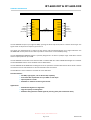
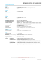
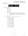
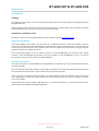
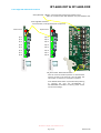
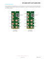
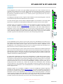
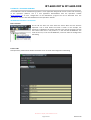
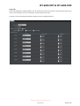
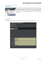
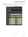
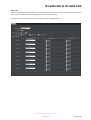
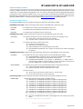
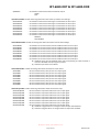
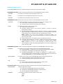
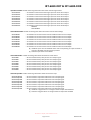
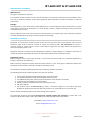
IRT-6690-DDT & IRT-6690-DDR
8 Channel ASI / SD-SDI Fibre Optic Link
User Manual
IRT Electronics Pty Ltd | www.irtelectronics.com
Page 1 of 22
Revision 00
IRT-6690-DDT & IRT-6690-DDR
8 Channel ASI / SD-SDI Fibre Optic Link
Revision History:
Revision
00
Date
30/10/2013
By
AL
Change Description
Original Issue.
Applicable to:
Firmware ≥
Revision 2.1
IRT Electronics Pty Ltd | www.irtelectronics.com
Page 2 of 22
Revision 00
IRT-6690-DDT & IRT-6690-DDR
USER MANUAL
Table of Contents:
Section
Page
Revision History
Operational Safety
openGear® Introduction
General Description
Technical Specifications
Configuration
DIP Switch Settings
Installation
Signal Inputs & Outputs
Fibre Optics Connection
Front Edge LED and Switch Location
Rear Assembly Layouts
Operation
IRT-6690-DDT
IRT-6690-DDR
DashBoard™ Software Control
IRT-6690-DDT DashBoard™ Screenshots
IRT-6690-DDR DashBoard™ Screenshots
SNMP Software Control
IRT-6690-DDT SNMP Functions
IRT-6690-DDR SNMP Functions
Maintenance & Storage
Warranty & Service
2
4
4
5
6
7
7
8
8
8
9
10
11
11
11
12
12
15
18
18
20
22
22
This instruction book applies to units fitted with firmware ≥ Revision 2.1.
IRT Electronics Pty Ltd | www.irtelectronics.com
Page 3 of 22
Revision 00
IRT-6690-DDT & IRT-6690-DDR
OPERATIONAL SAFETY
WARNING
Operation of electronic equipment involves the use of voltages and currents that
may be dangerous to human life. Note that under certain conditions dangerous
potentials may exist in some circuits when power controls are in the OFF position.
Maintenance personnel should observe all safety regulations.
Do not make any adjustments inside equipment with power ON unless proper
precautions are observed. All internal adjustments should only be made by suitably
qualified personnel. All operational adjustments are available externally without
the need for removing covers or use of extender cards.
openGear® INTRODUCTION
Developed by Ross Video, openGear® is a standard where various manufacturers can design their equipment to fit
a common frame allowing the end user to mix and match the various openGear® cards available in the market
place together in one frame. This allows a single frame to be used instead of multiple different vendor’s frames
that each would otherwise be using their own proprietary standard.
A simple to use monitoring and control software called DashBoard™ is a free program downloadable from the
openGear® website (www.opengear.tv) that allows the user to remotely monitor and control an openGear® type
card fitted within an openGear® frame that meets the openGear® standard for DashBoard™ control. A link is also
supplied via the IRT Electronics website (www.irtelectronics.com) under the openGear® navigation section.
IRT Electronics’ openGear® cards are designed to meet the openGear® standard for mounting within the
openGear® OG3-FR frame and its earlier version DFR-8300 frame, and is fully compliant with DashBoard™ control.
The openGear® frame manual, DashBoard™ control software and information regarding the frame’s power
supplies, controller card and frame accessories are available for download at the openGear® website.
The term openGear® is a registered trade mark of Ross Video Limited.
DashBoard software Control™ is a trade mark of Ross Video Limited.
IRT Electronics Pty Ltd | www.irtelectronics.com
Page 4 of 22
Revision 00
IRT-6690-DDT & IRT-6690-DDR
GENERAL DESCRIPTION
BLOCK DIAGRAM IRT-6690-DDT & IRT-6690-DDR SIGNAL PATH
IRT-6690-DDT
Any 8 x
270Mb/s
±100ppm
(ASI or SDI)
I/P 1
I/P 2
I/P 3
I/P 4
I/P 5
I/P 6
I/P 7
I/P 8
IRT-6690-DDR
O/P 1
O/P 2
O/P 3
Fibre O/P 4
Fibre
O/P 5
I/P
O/P
Fibre Link
O/P 6
9-27dB optical path loss
O/P 7
O/P 8
Any 8 x
270Mb/s
±100ppm
(ASI or SDI)
The IRT-6690-DDT accepts up to eight 270 Mb/s input signals which may be ASI, SDI or a mixture of each type. The
signals need not be phase or frequency synchronous.
The signals are multiplexed into a single 2.97 Gb/s stream and transmitted optically via a single mode fibre. The
IRT-6690-DDR receiver performs the reverse operation and restores correct 270 Mb/s timing.
The IRT-6690-DDT/IRT-6690-DDR system is primarily designed for use with a 9/125μm single mode fibre and will
allow an optical path loss up to 27dB.
The IRT-6690-DDT transmitter comes standard with a 1310nm DFB laser. Other CWDM wavelengths are available.
The IRT-6690-DDR receiver comes standard with an APD detector.
The IRT-6690-DDT & IRT-6690-DDR are designed to fit the openGear® standard 2RU frames which allow a mixture
of cards from various manufacturers to be mounted within the same frame.
The DashBoard™ control software is available as a free download.
Standard features:
• 270 Mb/s type signals, such as ASI and SDI, capability.
• Automatic cable equalisation for up to 300m on each input.
• Optical path loss ≥ 27dB.
• DashBoard™ software monitoring and control.
Applications:
• Multichannel digital on a single fibre.
• Upgrade capacity of existing fibre.
• Maintain timing between related signals by ensuring same path transmission delay.
IRT Electronics Pty Ltd | www.irtelectronics.com
Page 5 of 22
Revision 00
IRT-6690-DDT & IRT-6690-DDR
TECHNICAL SPECIFICATIONS
IRT-6690-DDT:
Inputs:
Type
Equalisation
Connectors
8 x independent ASI or SD-SDI.
Automatic for up to 300 m of Belden 8281 or equivalent cable.
BNC 75Ω.
Outputs:
Type
1 x 2.97 Gb/s optical
IRT-6690-DDR:
Inputs:
Type
1 x 2.97 Gb/s optical.
Outputs:
Type
Connectors
8 x independent ASI or SD-SDI.
BNC 75Ω.
Optical:
IRT-6690-DDT optical output
IRT-6690-DDR optical input
Available wavelengths
Optical path loss1
0 dBm +4.5/-0 dB CWDM DFB laser,
APD detector (standard), -9 to -27 dBm input level.
CWDM DFB laser - 1270nm, 1290nm, 1310nm (standard), 1330nm, 1350nm,
1370nm, 1390nm, 1410nm, 1430nm, 1450nm, 1470nm, 1490nm, 1510nm,
1530nm, 1550nm, 1570nm, 1590nm & 1610nm.
9 to 27 dB APD detector (standard), or
Optical fibre
Optical connectors
Designed for use with 9/125 μm single mode fibre.
1 x SC/PC (standard) on rear - direct connection to main card.
Power Requirements:
Voltage
Power consumption
+ 12 Vdc.
3 to 18 dB PIN detector.
IRT-6690-DDT < 6.5 VA, IRT-6690-DDR < 6 VA.
Other:
Temperature range
Mechanical
Dimensions (openGear® standard)
0 - 50° C ambient.
Suitable for mounting in an openGear® 2RU rack chassis.
33.6 mm x 2U x 325 mm.
Supplied accessories
Rear connector assembly.
Ordering
IRT-6690-DDT, programmed with DashBoard™ control.
IRT-6690-DDT, fitted with CWDM DFB laser other than 1310nm
where xxxx = wavelength required.
For example, IRT-6690-DDT/1550 is an IRT-6690-DDT fitted with a 1550nm laser.
IRT-6690-DDR fitted with APD detector, programmed with DashBoard™ control.
IRT-6690-DDR fitted with PIN detector, programmed with DashBoard™ control.
IRT-6690-DDT
IRT-6690-DDT/xxxx
IRT-6690-DDR
IRT-6690-DDR/PIN
Note:
1
Optical attenuator supplied for IRT-6690-DDR when optical path loss is less than
9dB for the APD detector and 3dB for the PIN detector.
Due to our policy of continuing development, these specifications are subject to change without notice.
IRT Electronics Pty Ltd | www.irtelectronics.com
Page 6 of 22
Revision 00
IRT-6690-DDT & IRT-6690-DDR
CONFIGURATION
DIP Switch settings:
DIP
ON
DIP
SW1
ON
1 2 3 4 5 6 7 8
1 2 3 4 5 6 7 8
SW2
IRT-6690-DDT & IRT-6690-DDR:
SW1-1 Not Used.
SW1-2 Not Used.
SW1-3 Not Used.
SW1-4 Not Used.
SW1-5 Not Used.
SW1-6 Not Used.
SW1-7 OFF
ON
DashBoard™/SNMP Control – Can disable individual channels and channel Traps.
DIP Switch Control – All channels are enabled (unless locked via
DashBoard™/SNMP or DIP Switch SW2 settings). Channel & Product Alias and
SNMP I/O Alarm Trap still settable via DashBoard™/SNMP regardless of SW1-7
switch position.
SW1-8 Not Used.
DIP Switch SW2-1 to SW2-8 only functional when set for DIP Switch Control (SW1-7 = ON).
SW2-1 OFF
ON
Channel 1 enabled.
Channel 1 disabled.
SW2-2 OFF
ON
Channel 2 enabled.
Channel 2 disabled.
SW2-3 OFF
ON
Channel 3 enabled.
Channel 3 disabled.
SW2-4 OFF
ON
Channel 4 enabled.
Channel 4 disabled.
SW2-5 OFF
ON
Channel 5 enabled.
Channel 5 disabled.
SW2-6 OFF
ON
Channel 6 enabled.
Channel 6 disabled.
SW2-7 OFF
ON
Channel 7 enabled.
Channel 7 disabled.
SW2-8 OFF
ON
Channel 8 enabled.
Channel 8 disabled.
IRT Electronics Pty Ltd | www.irtelectronics.com
Page 7 of 22
Revision 00
IRT-6690-DDT & IRT-6690-DDR
INSTALLATION
Pre-installation:
Handling:
This equipment may contain or be connected to static sensitive devices and proper static free handling precautions
should be observed.
Where individual circuit cards are stored, they should be placed in antistatic bags. Proper antistatic procedures
should be followed when inserting or removing cards from these bags.
Installation in openGear® frame:
See details in separate manual downloadable from the openGear® website (www.opengear.tv).
Signal Inputs & Outputs:
Up to eight 270Mb/s type of signals, such as ASI, SDI, or a combination of both, are fed into 75 Ω BNC connectors
on the rear connector panel of the IRT-6690-DDT. Unused inputs are best terminated with a 75 Ω termination to
avoid spurious noise being sent to the receiver where the front edge LEDs could illuminate and give the false
impression that there is a signal on that line.
The corresponding outputs are by 75 Ω BNC connectors on the IRT-6690-DDR rear connector panel. Output
numbers on the IRT-6690-DDR correspond to the input numbers on the IRT-6690-DDT. There is no need to
terminate the unused channel outputs on the IRT-6690-DDR.
Fibre Optic Connection:
The optical connectors on the IRT-6690-DDT & IRT-6690-DDR are attached to the main module PCB, NOT the rear
connector assembly.
When installing the optical fibre sufficient slack should be allowed for the module to be withdrawn with the optical
fibre attached until the connector is clear of the frame and can be disconnected.
If this is not done, the module will not be able to be removed without first disconnecting the optical fibre at the
rear. Attempting to remove the module without first disconnecting the fibre may result in damage to the fibre
and / or the module.
Note that for path lengths ≤ 9 dB for APD detectors, or ≤ 3 dB for PIN detectors, an optical attenuator must be
used to avoid over driving the IRT-6690-DDR detector.
IRT Electronics Pty Ltd | www.irtelectronics.com
Page 8 of 22
Revision 00
IRT-6690-DDT & IRT-6690-DDR
Front Edge LED and Switch Locations
Green/Red LED: GREEN – Communication with frame’s Network card.
RED - No communication with Network card / No Network card.
Front Edge LED Indicators
In this situation, all 8 inputs/outputs are present.
Laser Failure
Input Failure
I/P 1
O/P 1
I/P 2
O/P 2
I/P 3
O/P 3
I/P 4
O/P 4
I/P 5
O/P 5
I/P 6
O/P 6
I/P 7
O/P 7
I/P 8
O/P 8
IRT-6690-DDR
IRT-6690-DDT
SW_boot switch: Default Reset Switch.
User set names and switch position are stored within
memory so that in the event of a loss of power this
information is restored on resumption of power.
If the default Reset Switch is pressed whilst powering
or inserting the card, the IRT-6690-DDT or
IRT-6690-DDR will default to factory preset names
and channel settings.
IRT Electronics Pty Ltd | www.irtelectronics.com
Page 9 of 22
Revision 00
IRT-6690-DDT & IRT-6690-DDR
Rear Assembly Layouts
The IRT-6690-DDT and IRT-6690-DDR share a common generic rear assembly where the electrical signal BNC ports
are labelled as ‘CH–1’ to ‘CH–8’. Whether these correspond to an Input or an Output depends on which card the
rear assembly is fitted to.
O/P 1
I/P 1
Optical I/P
Optical O/P
I/P 2
O/P 2
I/P 3
I/P 4
O/P 3
O/P 4
I/P 5
I/P 6
O/P 5
O/P 6
I/P 7
I/P 8
O/P 7
O/P 8
IRT-6690-DDT
Rear Assembly
IRT-6690-DDR
Rear Assembly
IRT Electronics Pty Ltd | www.irtelectronics.com
Page 10 of 22
Revision 00
IRT-6690-DDT & IRT-6690-DDR
OPERATION
IRT-6690-DDT:
The IRT-6690-DDT will accept up to eight 270Mb/s type signals such as ASI or SD-SDI on the rear
assembly inputs marked ‘CH–1’ to ‘CH–8’. Input signals may all be of the same type or a mixture of
types just so long as they are all at the 270Mb/s rate. It is recommended that unused inputs be
terminated by 75 Ω BNC terminators so as to minimise spurious signal pickup which may cause a
false signal indication.
Front edge green LED’s light up when a signal has been detected on the corresponding input. A red Laser
Failure LED at the top of the board indicates if the laser has failed.
The input electrical signals are time division multiplexed together and converted to a 2.97 Gb/s optical
signal, which is outputted on an SC/PC (default standard) optical connector at the rear of the module.
IRT-6690-DDT
Individual inputs can be disabled via SNMP or the free DashBoard™ software application available
from the openGear® website (www.opengear.tv). This allows a limitation to be placed on the
number of available channels allowed to be used. Alternatively a DIP switch setting disables the
DashBoard™ control so that DashBoard™ can only be used for monitoring purposes - other than
naming of card and inputs. When DashBoard™ control has been disabled, all inputs are enabled
unless individually disabled via the DIP switch SW2 settings. When a channel has been disabled,
provided a signal has been detected on the channel, the corresponding LED will flash.
IRT-6690-DDR:
The IRT-6690-DDR receiver accepts an optical input signal from an IRT-6690-DDT transmitter via the
SC/PC (default standard) optical connector on the rear of the module. The optical signal is converted
into electrical form where electrical signals that have been time division multiplexed on the
IRT-6690-DDT are de-multiplexed into the same order as originally encoded and outputted on the
BNC connectors on the rear assembly marked as ‘CH–1’ to ‘CH–8’.
Green front edge LEDs light up when a signal within the stream is detected. A red Optical Input Failure
LED at the top of the board indicates if no optical input has been detected. When the optical level is
approaching the minimum input level, the optical alarm LED will flash green to indicate an Optical Low
state. Alarm thresholds can vary between detectors so signal integrity should be checked if an Optical Low
indication is observed as a matter of precaution.
Individual outputs can be disabled via SNMP or via the free DashBoard™ software application
available from the openGear® website (www.opengear.tv). This allows a limitation to be placed on
the number of available channels allowed to be used. Alternatively a DIP switch setting disables the
DashBoard™ control so that DashBoard™ can only be used for monitoring purposes - other than
naming of card and outputs. When DashBoard™ control has been disabled, all outputs are enabled
unless individually disabled via the DIP switch SW2 settings. When a channel has been disabled,
provided a signal has been detected on the channel, the corresponding LED will flash.
IRT-6690-DDR
For path lengths <9dB optical loss when using an APD detector, or <3dB optical loss when using a
PIN detector, an optical attenuator is required. The length of fibre that this corresponds to depends
on the fibre loss characteristics at the relevant wavelength of the laser module chosen. For example,
if the fibre loss characteristic of the chosen fibre is 0.2dB per kilometre at 1550 nm, say, then the
maximum distance that can be run is 135 km (27dB/0.2dBkm), although connector losses, such as
through patch lead connectors etc., should also be taken into consideration when calculating
maximum distances. Actual attenuation versus wavelength characteristics depends upon optic fibre
manufacturer’s own specifications. Also a few dB headroom is recommended to allow for the effects
of laser aging over time.
IRT Electronics Pty Ltd | www.irtelectronics.com
Page 11 of 22
Revision 00
IRT-6690-DDT & IRT-6690-DDR
DashBoard™ SOFTWARE CONTROL
The DashBoard™ Control and Monitoring System is a free application designed for remote control and monitoring
of the openGear® platform. This is a free application downloadable from the openGear® website
(www.opengear.tv). As such, configuration of the DashBoard™ program will not be described here. The
DashBoard™ manual is also downloadable from the openGear® website.
IRT-6690-DDT DashBoard™ Screenshots:
Basic Tree View:
On the left the basic tree view shows the frame. With the tree structure
expanded a list of cards within the frame is shown. In this example, slot
position 6 is highlighted. All sections and tabs to the right of the basic tree view
now relate to the card in slot position 6, in this case the IRT-6690-DDT. The
name of the card, in this case IRT-6690-DDT, can be set under the Configuration
TAB setting.
Product TAB:
Self explanatory. Note that the Product Alias field can be set under the Configuration TAB setting.
IRT Electronics Pty Ltd | www.irtelectronics.com
Page 12 of 22
Revision 00
IRT-6690-DDT & IRT-6690-DDR
Status TAB:
Status TAB shows the set input names (Alias) corresponding to each input channel number, these being set under
the Configuration TAB in the second half of the DashBoard™ frame (see next screenshot), as well as information
about the optical laser fitted and the status of the channel inputs.
IRT Electronics Pty Ltd | www.irtelectronics.com
Page 13 of 22
Revision 00
IRT-6690-DDT & IRT-6690-DDR
Config TAB:
Under the Configuration TAB parameters such as Product Alias (name) and channel names (Channel Alias) can be
user set. Click computer mouse into the field to change and type new name.
Channels can also be individually enabled or disabled, as well as TRAP generations.
IRT Electronics Pty Ltd | www.irtelectronics.com
Page 14 of 22
Revision 00
IRT-6690-DDT & IRT-6690-DDR
IRT-6690-DDR DashBoard™ Screenshots:
Basic Tree View:
On the left the basic tree view shows the frame. With the tree structure
expanded a list of cards within the frame is shown. In this example, slot
position 8 is highlighted. All sections and tabs to the right of the basic tree view
now relate to the card in slot position 8, in this case the IRT-6690-DDR. The
name of the card, in this case IRT-6690-DDR, can be set under the Configuration
TAB setting.
Product TAB:
Self explanatory. Note that the Product Alias field can be set under the Configuration TAB setting.
IRT Electronics Pty Ltd | www.irtelectronics.com
Page 15 of 22
Revision 00
IRT-6690-DDT & IRT-6690-DDR
Status TAB:
Status TAB shows the set output names (Alias) corresponding to each output channel number, these being set
under the Configuration TAB in the second half of the DashBoard™ frame (see next screenshot), as well as
information about the optical detector fitted and the status of the channel outputs.
IRT Electronics Pty Ltd | www.irtelectronics.com
Page 16 of 22
Revision 00
IRT-6690-DDT & IRT-6690-DDR
Config TAB:
Under the Configuration TAB parameters such as Product Alias (name) and channel names (Channel Alias) can be
user set. Click computer mouse into the field to change and type new name.
Channels can also be individually enabled or disabled, as well as TRAP generations.
IRT Electronics Pty Ltd | www.irtelectronics.com
Page 17 of 22
Revision 00
IRT-6690-DDT & IRT-6690-DDR
SNMP SOFTWARE CONTROL
Control via SNMP is possible via a third party Network Management System (NMS) provided the openGear® frame
is fitted with a relevant Network Management card. In the case of the OG3-FR frame the MFC-8322-NS network
management card is required for SNMP control. In the case of either the DFR-8310 or DFR-8321 frames either the
MFC-8310-NS or MFC-8320-NS cards are required for SNMP control. Relevant frame MIBs and card MIB required to
interface to NMS software - see IRT Electronics website (www.irtelectronics.com) for MIB download.
IRT-6690-DDT SNMP Functions:
The following SNMP functions are capable of being controlled and monitored by an NMS:
irt6690DDTProductTable: A table containing product info for all IRT-6690-DDT cards at this node.
productAlias
- An indication and control of the Alias (Name) of this card.
boardRev
- An indication of the hardware (board) revision of this card.
softwareRev
- An indication of the software revision of this card.
irt6690DDTStatusTable: A table containing alarm status for all IRT-6690-DDT cards at this node.
rearassembly
- An indication whether the card is inserted into the correct rear assembly or not:
(1) match: Card is inserted into correct rear assembly.
(2) mismatch: Card is inserted into incorrect rear assembly.
ioAlarm
- An indication of the alarm status of this card:
(0) noAlarm: No alarms present.
(1) opticalFail: Laser output has failed.
(2) allChannelsAbsent: No valid input signals are present.
(3) opticalFailAllChannelsAbsent: Laser output has failed and no valid input signals
are present.
irt6690DDTSettingsTable: A table containing configuration settings for all IRT-6690-DDT cards at this node.
controlMode
- An indication of the control settings made as per the PCB DIP switch setting:
(0) dashboardSNMP: Card settings can be controlled via DashBoard™ or SNMP.
(1) pcbSwitches: Card settings as per DIP switch settings only.
(2) lockedtoDashboardSNMP: Lock module to DashBoard™ or SNMP control –
overrides SW1-7 position. Note that SW1-7 must be initially ON to be able to set
to Lock to SNMP mode. To release send either a (0) or (1).
ioAlarmTrapEnable
- An indication and control of Trap enable/disable function of input/output alarms:
(0) ioAlarmTrapDisable: Disable input/output alarm Traps.
(1) ioAlarmTrapEnable: Enable input/output alarm Traps.
reset
- Unit reset control:
(0) normal: when queried reset control returns a ‘normal’ state.
(1) reset: system reset causes a reset of the card.
opticalSettingsTable: A table containing information about the optical components fitted to the card.
laserWavelength
- Wavelength information about the transmitter section:
(1) nm1470Laser: IRT-6690-DDT fitted with a 1470nm wavelength laser.
(2) nm1490Laser: IRT-6690-DDT fitted with a 1490nm wavelength laser.
(3) nm1510Laser: IRT-6690-DDT fitted with a 1510nm wavelength laser.
(4) nm1530Laser: IRT-6690-DDT fitted with a 1530nm wavelength laser.
(5) nm1550Laser: IRT-6690-DDT fitted with a 1550nm wavelength laser.
(6) nm1570Laser: IRT-6690-DDT fitted with a 1570nm wavelength laser.
(7) nm1590Laser: IRT-6690-DDT fitted with a 1590nm wavelength laser.
(8) nm1610Laser: IRT-6690-DDT fitted with a 1610nm wavelength laser.
(15) nm1310Laser: IRT-6690-DDT fitted with a 1310nm wavelength laser.
(16) wideband: Not applicable to the IRT-6690-DDT.
(17) unknown: IRT-6690-DDT fitted with a wavelength laser not matching any of the
above.
(18) na: Not applicable to the IRT-6690-DDT.
IRT Electronics Pty Ltd | www.irtelectronics.com
Page 18 of 22
Revision 00
IRT-6690-DDT & IRT-6690-DDR
opticalStatus
- An indication of the status of the transmitter output:
GOOD
FAIL.
inputPresentTable: A table containing information about the input status and settings.
channel1Present
channel2Present
channel3Present
channel4Present
channel5Present
channel6Present
channel7Present
channel8Present
-
An indication of the status of the signal connected to the CH-1 input.
An indication of the status of the signal connected to the CH-2 input.
An indication of the status of the signal connected to the CH-3 input.
An indication of the status of the signal connected to the CH-4 input.
An indication of the status of the signal connected to the CH-5 input.
An indication of the status of the signal connected to the CH-6 input.
An indication of the status of the signal connected to the CH-7 input.
An indication of the status of the signal connected to the CH-8 input.
PRESENT
NOT PRESENT
channelEnableTable: A table containing information about the channel state settings.
channel1Enable
channel2Enable
channel3Enable
channel4Enable
channel5Enable
channel6Enable
channel7Enable
channel8Enable
-
An indication and control of the channel enable function for CH-1 input.
An indication and control of the channel enable function for CH-2 input.
An indication and control of the channel enable function for CH-3 input.
An indication and control of the channel enable function for CH-4 input.
An indication and control of the channel enable function for CH-5 input.
An indication and control of the channel enable function for CH-6 input.
An indication and control of the channel enable function for CH-7 input.
An indication and control of the channel enable function for CH-8 input.
(0) disabled: Input channel disabled. Note: LED corresponding to input will flash if
channel is disabled and input signal is present.
(1) enabled: Input channel is enabled.
channelAliasTable: A table containing information about the channel aliases.
channel1Alias
channel2Alias
channel3Alias
channel4Alias
channel5Alias
channel6Alias
channel7Alias
channel8Alias
-
Set and read the Alias (name) for the CH-1 input signal.
Set and read the Alias (name) for the CH-2 input signal.
Set and read the Alias (name) for the CH-3 input signal.
Set and read the Alias (name) for the CH-4 input signal.
Set and read the Alias (name) for the CH-5 input signal.
Set and read the Alias (name) for the CH-6 input signal.
Set and read the Alias (name) for the CH-7 input signal.
Set and read the Alias (name) for the CH-8 input signal.
channelTrapTable: A table containing information about the channel Traps.
channel1TrapEnable
channel2 TrapEnable
channel3 TrapEnable
channel4 TrapEnable
channel5 TrapEnable
channel6 TrapEnable
channel7 TrapEnable
channel8 TrapEnable
-
Set and read the Trap enable state for the CH-1 input signal.
Set and read the Trap enable state for the CH-2 input signal.
Set and read the Trap enable state for the CH-3 input signal.
Set and read the Trap enable state for the CH-4 input signal.
Set and read the Trap enable state for the CH-5 input signal.
Set and read the Trap enable state for the CH-6 input signal.
Set and read the Trap enable state for the CH-7 input signal.
Set and read the Trap enable state for the CH-8 input signal.
(0) disabled: Trap generation on change of channel input state disabled.
(1) enabled: Trap generation on change of channel input state enabled.
IRT Electronics Pty Ltd | www.irtelectronics.com
Page 19 of 22
Revision 00
IRT-6690-DDT & IRT-6690-DDR
IRT-6690-DDR SNMP Functions:
The following SNMP functions are capable of being controlled and monitored by an NMS:
irt6690DDRProductTable: A table containing product info for all IRT-6690-DDR cards at this node.
productAlias
- An indication and control of the Alias (Name) of this card.
boardRev
- An indication of the hardware (board) revision of this card.
softwareRev
- An indication of the software revision of this card.
irt6690DDRStatusTable: A table containing alarm status for all IRT-6690-DDR cards at this node.
rearassembly
- An indication whether the card is inserted into the correct rear assembly or not:
(1) match: Card is inserted into correct rear assembly.
(2) mismatch: Card is inserted into incorrect rear assembly.
ioAlarm
- An indication of the alarm status of this card:
(0) noAlarm: No alarms present.
(1) opticalFail: Optical input to the receiver’s detector is below its minimum
threshold or has failed.
(2) opticalLowAllChannelsAbsent: Optical detector of receiver is reporting that the
optical input signal is approaching its minimum, or has exceeded its, allowable
signal strength; and no valid signal has been received by the receiver.
NOTE: Detectors can vary in their reporting of optical low state. It is
recommended to confirm that the received signal is error free if an Optical Low
alarm has been raised.
(4) allChannelsAbsent: No valid signal has been received by the receiver.
(8) opticalLow: Optical detector of receiver is reporting that the optical input signal
is approaching its minimum, or has exceeded its, allowable signal strength.
NOTE: Detectors can vary in their reporting of optical low state. It is
recommended to confirm that the received signal is error free if an Optical Low
alarm has been raised.
irt6690DDRSettingsTable: A table containing configuration settings for all IRT-6690-DDR cards at this node.
controlMode
- An indication of the control settings made as per the PCB DIP switch setting:
(0) dashboardSNMP: Card settings can be controlled via DashBoard™ or SNMP.
(1) pcbSwitches: Card settings as per DIP switch settings only.
(2) lockedtoDashboardSNMP: Lock module to DashBoard™ or SNMP control –
overrides SW1-7 position. Note that SW1-7 must be initially ON to be able to set
to Lock to SNMP mode. To release send either a (0) or (1).
ioAlarmTrapEnable
- An indication and control of Trap enable/disable function of input/output alarms:
(0) ioAlarmTrapDisable: Disable input/output alarm Traps.
(1) ioAlarmTrapEnable: Enable input/output alarm Traps.
reset
- Unit reset control:
(0) normal: when queried reset control returns a ‘normal’ state.
(1) reset: system reset causes a reset of the card.
opticalSettingsTable: A table containing information about the optical components fitted to the card.
optical1Component
- Detector type of the receiver:
(1) pinDetector: IRT-6630-DDR fitted with a PIN detector.
(2) apdDetector: IRT-6630-DDR fitted with an APD detector.
(3) na: Not applicable. No detector fitted.
opticalStatus
- An indication of the status of the receiver optical input:
GOOD
LOW
FAIL.
IRT Electronics Pty Ltd | www.irtelectronics.com
Page 20 of 22
Revision 00
IRT-6690-DDT & IRT-6690-DDR
inputPresentTable: A table containing information about the received signal status.
channel1Present
channel2Present
channel3Present
channel4Present
channel5Present
channel6Present
channel7Present
channel8Present
-
An indication of the status of the signal presence at the CH-1 output.
An indication of the status of the signal presence at the CH-2 output.
An indication of the status of the signal presence at the CH-3 output.
An indication of the status of the signal presence at the CH-4 output.
An indication of the status of the signal presence at the CH-5 output.
An indication of the status of the signal presence at the CH-6 output.
An indication of the status of the signal presence at the CH-7 output.
An indication of the status of the signal presence at the CH-8 output.
PRESENT
NOT PRESENT
channelEnableTable: A table containing information about the channel state settings.
channel1Enable
channel2Enable
channel3Enable
channel4Enable
channel5Enable
channel6Enable
channel7Enable
channel8Enable
-
An indication and control of the channel enable function for CH-1 output.
An indication and control of the channel enable function for CH-2 output.
An indication and control of the channel enable function for CH-3 output.
An indication and control of the channel enable function for CH-4 output.
An indication and control of the channel enable function for CH-5 output.
An indication and control of the channel enable function for CH-6 output.
An indication and control of the channel enable function for CH-7 output.
An indication and control of the channel enable function for CH-8 output.
(0) disabled: Input channel disabled. Note: LED corresponding to input will flash if
channel is disabled and input signal is present.
(1) enabled: Input channel is enabled.
channelAliasTable: A table containing information about the channel aliases.
channel1Alias
channel2Alias
channel3Alias
channel4Alias
channel5Alias
channel6Alias
channel7Alias
channel8Alias
-
Set and read the Alias (name) for the CH-1 output signal.
Set and read the Alias (name) for the CH-2 output signal.
Set and read the Alias (name) for the CH-3 output signal.
Set and read the Alias (name) for the CH-4 output signal.
Set and read the Alias (name) for the CH-5 output signal.
Set and read the Alias (name) for the CH-6 output signal.
Set and read the Alias (name) for the CH-7 output signal.
Set and read the Alias (name) for the CH-8 output signal.
channelTrapTable: A table containing information about the channel Traps.
channel1TrapEnable
channel2 TrapEnable
channel3 TrapEnable
channel4 TrapEnable
channel5 TrapEnable
channel6 TrapEnable
channel7 TrapEnable
channel8 TrapEnable
-
Set and read the Trap enable state for the CH-1 output signal.
Set and read the Trap enable state for the CH-2 output signal.
Set and read the Trap enable state for the CH-3 output signal.
Set and read the Trap enable state for the CH-4 output signal.
Set and read the Trap enable state for the CH-5 output signal.
Set and read the Trap enable state for the CH-6 output signal.
Set and read the Trap enable state for the CH-7 output signal.
Set and read the Trap enable state for the CH-8 output signal.
(0) disabled: Trap generation on change of channel input state disabled.
(1) enabled: Trap generation on change of channel input state enabled.
IRT Electronics Pty Ltd | www.irtelectronics.com
Page 21 of 22
Revision 00
IRT-6690-DDT & IRT-6690-DDR
MAINTENANCE & STORAGE
Maintenance:
No regular maintenance is required.
Care however should be taken to ensure that all connectors are kept clean and free from contamination of any
kind. This is especially important in fibre optic equipment where cleanliness of optical connections is critical to
performance.
Storage:
If the equipment is not to be used for an extended period, it is recommended the whole unit be placed in a sealed
plastic bag to prevent dust contamination. In areas of high humidity a suitably sized bag of silica gel should be
included to deter corrosion.
Where individual circuit cards are stored, they should be placed in antistatic bags. Proper antistatic procedures
should be followed when inserting or removing cards from these bags.
WARRANTY & SERVICE
Equipment is covered by a limited warranty period of three years from date of first delivery unless contrary
conditions apply under a particular contract of supply. For situations when “No Fault Found” for repairs, a
minimum charge of 1 hour’s labour, at IRT’s current labour charge rate, will apply, whether the equipment is
within the warranty period or not.
Equipment warranty is limited to faults attributable to defects in original design or manufacture. Warranty on
components shall be extended by IRT only to the extent obtainable from the component supplier.
Equipment return:
Before arranging service, ensure that the fault is in the unit to be serviced and not in associated equipment. If
possible, confirm this by substitution.
Before returning equipment contact should be made with IRT or your local agent to determine whether the
equipment can be serviced in the field or should be returned for repair.
The equipment should be properly packed for return observing antistatic procedures.
The following information should accompany the unit to be returned:
1.
2.
3.
4.
5.
6.
7.
A fault report should be included indicating the nature of the fault
The operating conditions under which the fault initially occurred.
Any additional information, which may be of assistance in fault location and remedy.
A contact name and telephone and fax numbers.
Details of payment method for items not covered by warranty.
Full return address.
For situations when “No Fault Found” for repairs, a minimum charge of 1 hour’s labour will apply,
whether the equipment is within the warranty period or not. Contact IRT for current hourly rate.
Please note that all freight charges are the responsibility of the customer.
The equipment should be returned to the agent who originally supplied the equipment or, where this is not
possible, to IRT directly. Details of IRT’s direct address can be found at IRT Electronics’ website.
Web address: www.irtelectronics.com
Email: [email protected]
IRT Electronics Pty Ltd | www.irtelectronics.com
Page 22 of 22
Revision 00