1
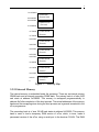
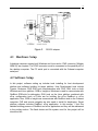
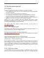
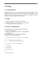
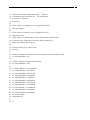
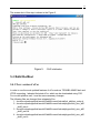
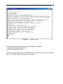
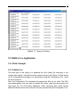
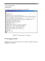
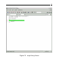
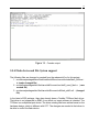
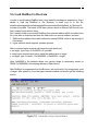
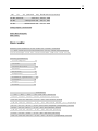
1 Port of RedHat eCos to the CubeSat Computer Qiuping Tao September 10, 2004 Supervised by Professor Michel Barbeau 2 1. Abstract This project intends to port the eCos RTOS to the Cubesat computer which is a single board computer that fits inside a 10 cm cube satellite, create a file system to access the flash device in order to provide the ability to save the data when the power is shut off, also perform the benchmark testing for the new ported operating system. 3 2 Table of Contents 1 . Abstract………………………………………………………………………………….2 2. Table of Contents………………………………………………………………………..3 3. Introduction…………………………………………………………………………….…5 3.1 eCos…………………………………………………………………………………..5 3.1.1 Core functionality……………………………………………………………..5 3.1.2 Cofigurability…………………………………………………………………..6 3.1.3 Processor and Evaluation platform support………………………………..6 3.1.4 eCos support………………………………………………………………….7 3.2 CubeSat………………………………………………………………………………7 3.2.1 Processor………………………………………………………………………7 3.2.2 Memory Map…………………………………………………………………..8 3.2.2.1 Internal Memory………………………………………………………..8 3.2.2.2 External Memory……………………………………………………….9 3.2.3 Peripherals…………………………………………………………………….9 3.2.3.1 Serial Communication…………………………………………………9 4. Development Setup……………………………………………………………………..11 4.1 Hardware Setup……………………………………………………………………..11 4.2 Software Setup……………………………………………………………………...12 4.2.1 Host Development Platform…………………………………………………13 4.2.1.1. Cygwin…………………………………………………………………13 4.2.1.2 GNU Tools on Cygwin………………………………………………..13 4.2.1.3 GNU Tools on Linux…………………………………………………..13 4.2.1.4 CVS…………………………………………………………………….14 4.2.1.5 Source Navigator……………………………………………………..14 4.2.1.6 Configuration Tool…………………………………………………….14 4.2.2 RedBoot………………………………………………………………………14 4.2.3 eCos…………………………………………………………………………..15 4.2.3.1 Architecture Overview………………………………………………..15 4.2.3.2 eCos Repository………………………………………………………16 4.2.3.3 eCos Terminology…………………………………………………….17 4.2.3.4 eCos Configuration Option…………………………………………..17 4.2.4 Flash Device………………………………………………………………….18 4.2.5 File System JFFS2…………………………………………………………..19 5. Porting……………………………………………………………………………………20 5.1 Target Platform……………………………………………………………………. .20 5.2 Setup…………………………………………………………………………………20 5.3 JTAG Communication………………………………………………………………20 5.4 Building RedBoot……………………………………………………………………22 5.4.1 New Version eCos…………………………………………………………...22 4 5.4.2 Build..……………………………………………………………………….23 5.4.3 Loading RedBoot to RAM………………………………………………. 24 5.4.4 Debugging using RedBoot……………………………………………….25 5.5 Building eCos Application……………………………………………………….29 5.5.1 Hello Example……………………………………………………………..29 5.5.2 Loading Hello to RAM…………………………………………………….30 5.5.3 Debugging Hello…………………………………………………………...31 5.5.4 Flash Driver Support………………………………………………………31 5.5.5 File System Support………………………………………………………32 5.6 Loading RedBoot to Bootrom…………………………………………………..32 6. Reference……………………………………………………………………………..33 5 3 Introduction The RTOS operating system eCos and the Cubesat computer are introduced as followings: 3.1 eCos eCos is an open source, royalty-free, real-time operating system form Red Hat Inc, intended for embedded applications. GNU open source development tools support eCos. The highly configurable nature of eCos allows the operating system to be customized to precise application requirements, delivering the best possible run-time performance and an optimized hardware resource footprint. A thriving net community has grown up around the operating system ensuring on-going technical innovation and wide platform support. 3.1.1 Core functionality As a RTOS, the following core functionality is provided: • • • • • • • • • Hardware Abstraction Layer (HAL) Real-time kernel o Interrupt handling o Exception handling o Choice of schedulers o Thread support o Rich set of synchronization primitives o Timers, counters and alarms o Choice of memory allocates o Debug and instrumentation support µITRON 3.0 compatible API POSIX compatible API ISO C and math libraries Serial, Ethernet, wallclock and watchdog device drivers USB slave support TCP/IP networking stacks GDB debug support 6 3.1.2 Configurability One of the key technological innovations in eCos is the configuration system. It is important to understand that the component framework makes up the eCos system. Developers are able to select components that satisfy basic application needs, and configure that particular component for the specific implementation requirements for the application. The configurability minimizes the code size, minimize the memory use, and therefore reduce the error. There are several eCos configuration methods: Run time – No up-front configuration of component is done. Typically run time control is through Dynamic Link Library. Link time – GNU provide the link-time control, or selective linking. With the selective linking, unreferenced functions and data are removed from the application image. Compile time – Gives the developer control of the component behavior at the earliest stage, allow the implementation of the component itself to be built for specific application for which it is intended. Compile time control gives the best results in terms of the code size because the control is at the individual statement level in the source code rather than at the function or object level. Using compile time or source level configuration is achieved by using C preprocessor. eCos uses compile-time control methods for its software components, along with the selective linking provided by the GNU linker. The Configuration Tool, provided with the eCos release, ease the selection and configuration of the software components. 3.1.3 Processor and Evaluation Platform Support eCos is designed to be portable to a wide range of target architectures and target platforms including 16, 32, and 64 bit architectures, MPUs, MCUs and DSPs. The eCos kernel, libraries and runtime components are layered on the Hardware Abstraction Layer (HAL), and thus will run on any target once the HAL and relevant device drivers have been ported to the target's processor architecture and board. Currently eCos supports ten different target architectures (ARM, Hitachi H8300, Intel x86, MIPS, Matsushita AM3x, Motorola 68k, PowerPC, SuperH, SPARC and NEC V8xx) including many of the popular variants of these architectures and evaluation 7 boards. Many new ports are in development and will be released as they become available. 3.1.4 eCos Support There are six different mailing lists available for the eCos projects: Discussion List – Contains support and technical assistance on various topic about the eCos project from developers. I used this list several times. Patches List – used for submitting eCos patches for approval by the maintainers before they are committed to the source code repository. Development List – include discussion about current enhancements being developed, such as new ports and new features. Announcement List – a low-volume list for significant news about eCos that is also used to announce new eCos release or major feature enhancements. CVS Web Pages List – contains notifications of changes to the eCos web pages that are maintained in Concurrent Version System (CVS). CVS List – a read-onlu list that gives notifications of changes made to the eCos source code repository. The detailed information can be found at http://ecos.sourceware.org/intouch.html. 3.2 CubeSat The Cubesat computer is a single board computer that fits inside a 10 cm cube satellite 3.2.1 Processor The processor of the Cubesat Computer is an Atmel AT91R40807, which is in fact a small system with a CPU, internal memory and controllers for interfacing with peripherals. The CPU is an ARM7TDMI ARM Thumb Processor Core. 3.2.2 Memory Map The Cubesat Computer has internal memory (embedded in the Atmel processor) and external memory (on the Cubesat Computer board), see Figure 1. Memory banks are not contiguous, but this is rather immaterial to the eCos programmer. 8 Ox12000000 0x10000000 0x01020000 0x01000000 0x780000 0x700000 0x680000 0x600000 0x580000 0x500000 0x480000 0x400000 0x120000 0x100000 0x2000 0 NAND Flash (External 32M) 128KB bootrom (External) 512 KB SRAM (External) 512 KB SRAM (External) 512 KB SRAM (External) 512 KB SRAM (External) 128 KB SRAM (Internal) 8 KB SRAM (Internal) Figure 1. Memory Map 3.2.2.1 Internal Memory The internal memory is embedded inside the processor. There are an internal primary SRAM bank and an internal secondary SRAM bank. The primary bank is of size 8 KB and starts at address 0x300000. This memory is remapped programmatically to address 0x0 after completion of the boot process. The actual addresses of the memory banks and the remapping done during the boot process are in general immaterial to the eCos programmer. The secondary bank is of size 128 KB and starts at address 0x100000. This memory bank is used to load a temporary RAM version of eCos, which, in turns, loads a permanent version of the eCos, using a serial port in the bootrom FLASH. The RAM 9 version of eCos is also useful during debugging. 3.2.2.2 External Memory The external memory is provided by memory chips connected to the Atmel processor. The processor communicates with the external memory using the External Bus Interface (EBI). There are three kinds of external memory: the bootrom, SRAM and FLASH for long-term storage. The bootrom is of size 128 KB and starts at address 0x0 (if no remap has been done). When the Cubesat Computer is booted or a reset is done, execution starts at address 0x0 in the bootrom. It is normally a jump instruction to another location in the bootrom. The bootrom is visible at address 0x1000000 after the remap. The bootrom is provided by a FLASH memory chip, which can be loaded and re-loaded with code. The FLASH memory chip can also be substituted by an EPROM chip, which cannot be loaded. The external SRAM is of size 2 MB and is divided in two banks of 1 MB. The start addresses of the external memory are all above 0x400 000 and are reconfigurable programmatically. The start addresses of the banks are configured to start respectively at addresses 0x480 000 and 0x680 000. The FLASH memory for long-term storage is of size 32 MB and is located at address 0x10000000. An access to the FLASH memory requires multiple-clock cycle. The communication protocol is not directly supported by the EBI. 3.2.3 Peripherals Peripherals include serial port and parallel port. 3.2.3.1 Serial Communications The Atmel processor has two internal Universal Synchronous/Asynchronous Receiver/Transmitters (USARTs), namely, USART0 and USART1. They are memory mapped to the respective addresses 0xFFFD0000 and 0xFFFC000. For the eCos programmer, they also appear as the /dev/tty0 and /dev/tty1 serial device abstractions. The USART0 has a half duplex FSK modem connected to it. The USART1 is connected to a multiplexer circuitry. The circuitry multiplexes three serial lines available for communication with peripherals (Port 0, 1 and 2) and a Dallas 1 chip providing environmental data (Port 3). 10 The port number (0..3) is selected by writing the corresponding binary value (00..11) on the PIO output lines number 19 and 20, it is Port 0 by default. 11 4 Development setup The development setup is pictured in figure 3.1. Figure 2. Development Setup The first serial line of USART1 (called Port 0) is used to provide a eCos console. Port 0 is available using transmit line stxd0 (Pin 17 on the P100 connector) and receive line srxd0 (Pin 18 on the P100 connector). The console itself is provided a by terminal emulation program on a PC. The serial port of the PC (e.g. COM1) is connected to Port 0 of the Cubesat Computer with a serial communication cable (i.e. RS-232). The Cubesat Computer does not include the interface circuit needed for the conversion of the TTL signals of Port 0 (binary 1 is a positive voltage level between 2 V to 5 V, binary 0 is positive voltage between 0 volts to 0.8 volts) to the RS-232 signals (binary 1 (mark) is a voltage between minus 3 volts and minus 15 volts, binary 0 (space) is a voltage between plus 3 volts to 15 volts). An interface circuit based on the Maxim MAX233A RS-232 Drivers/Receivers chip is proposed, see Figure 3.2. The advantage of this circuit is that it does not require an additional supply of 5 volts nor external capacitance. The MAX233A needs to be supplied with plus 5 volts (Pin 7). This voltage is taken from the DTR line of the PC and regulated by the 78L05. 12 Figure 3. RS-232 adapter. 4.1 Hardware Setup A desktop computer running both Windows and Linux and a JTAG connector (Wiggler ARM 20) are required. The JTAG connector must be connected on the parallel port of the desktop computer. The PC serial port is connected with the Cubesat computer serial port. 4.2 Software Setup In this project, software setting up includes tools installing for host development platform and software building for target platform. Host Development tools include Cygwin, Ocdemon JTAG GNU tools communication with JTAG, GNU tools on both Windows and Linux platform. GDB or Insight on Windows is used to communicate with RedBoot GDB stub for debugging. GNU tools on the Linux platform combined with eCos configuration tools on Linux are for building the eCos RedBoot or eCos application. Also, GDB or Insight can communicate with RedBoot stub on the Cubesat computer. CVS and source navigator are also need to install for developing. Target platform software includes RedBoot, eCos application. In this section, I omit the detailed building process of RedBoot and eCos application and they will be addressed in the porting section. The flash device and file system used for this project will be introduced too. 13 4.2.1 Host development platform 4.2.1.1 Cygwin Cygwin is a Linux-like environment for Windows. It consists of two parts: A DLL (cygwin1.dll), which acts as a Linux emulation layer providing substantial Linux API functionality. A collection of tools, which provide Linux look and feel. The Cygwin DLL works with all non-beta, non "release candidate", ix86 32 bit versions of Windows since Windows 95, with the exception of Windows CE. Cygwin is not a way to run native Linux apps on Windows. You have to rebuild your application from source if you want to get it running on Windows. Cygwin is not a way to magically make native Windows apps aware of UNIX functionality, like signals, ptys, etc. Again, you need to build your apps from source if you want to take advantage of Cygwin functionality. The source code and http://www.cygwin.com/. detailed installing instruction can be found on 4.2.1.2 GNU Tools on Cygwin The Ocdemon JTAG GNU tools are provided by OCDemon Macraigor Systems. It is used to communication with JTAG (Wiggler ARM 20). The source code and installing information can be found on http://www.macraigor.com/full_gnu.htm. During GNU Tools installation, files are placed in the following directories: cygwin/usr/local/bin - binary GNU tools + OCDemon binaries. cygwin/usr/local/OCDEMON - (cpu type) - example - example source & makefile. windows/system - OCDemon support binaries. On the Cygwin environment, I need to install another set of GNU tools if you choose prefer debugging code on the Windows platform. Since the GUN tools provided by Ocdemon Macraigor don’t have source-level debugging capability, so I installed a most recent version of GUN tools. The source code and installation instruction can be found on http://www.gnu.org. 4.2.1.3 GNU tools on Linux I built the RedBoot and eCos on the Linux platform, so ARM based GNU tools need to install on the Linux including GNU Binary utilities, GNU C/C++ Compiler and GUN 14 Insight Debugger with Insight Interface. The source code and installing instruction can be found on http://www.gnu.org. 4.2.1.4 CVS CVS is the Concurrent Versions System, the dominant open source network transparent version control system. CVS is useful for everyone from individual developers to large, distributed teams: Its client-server access method lets developers access the latest code from anywhere there's an Internet connection. Its unreserved check-out model to version control avoids artificial conflicts common with the exclusive check-out model. Its client tools are available on most platforms. Using CVS in this project, I downloaded the most recent version of eCos. The source code of CVS and installing instruction can be found on http://www.gnu.org/software/cvs/ 4.2.1.5 Source Navigator Source-Navigator is a source code analysis tool. With it, you can edit your source code, display relationships between classes and functions and members, and display call trees. You can also build your projects, either with your own makefile, or by using Source-Navigator's build system to automatically generate a makefile. • • • • Analyze how a change will affect external source modules. Find every place in your code where a given function is called. Find each file that includes a given header file. Use the grep tool to search for a given string in all your source files. The source code and installing instruction can be found at http://sourcenav.sourceforge.net/ 4.2.1.6 Configuration Tool The Configuration Tool provides the ability to customize the eCos library to meet the specific application needs through source-level configuration. Using Configuration Tool, I can build the RedBoot and eCos application. The Configuration source code is in the eCos repository. 4.2.2 RedBoot RedBoot is a complete bootstrap environment for embedded systems. Based on the eCos Hardware Abstraction Layer, RedBoot inherits the eCos qualities of reliability, compactness, configurability, and portability. 15 RedBoot allows download and execution of embedded applications via serial or Ethernet, including embedded Linux and eCos applications. It can be used for both product development (debug support) and in deployed products in the field (flash update and network booting). Ethernet download and debug support is included, allowing RedBoot to retrieve its IP parameters via BOOTP or DHCP, and program images to be downloaded using TFTP. Images can also be downloaded over serial, using X- or Y-modem. RedBoot can be used to communicate with GDB (the GNU Debugger) to debug applications via serial or Ethernet, including the ability to interrupt a running application started by GDB. An interactive command-line interface is provided to allow management of the Flash images, image download, RedBoot configuration, etc., accessible via serial or Ethernet. For unattended or automated startup, boot scripts can be stored in Flash allowing for example loading of images from Flash or a TFTP server. 4.2.3 eCos Section 3.1 Briefly introduced the eCos. In this section, we’ll have more detailed explanations. 4.2.3.1 Architecture Overview eCos is designed as a configurable component architecture consisting of several key software components such as the Kernel and HAL. The architecture overview can be viewed in Figure4. 16 UITRON POSIX Compatibility C Math Libraries Web Server File System Networking Kernel Stack Hardware Abstraction Layer Device Driver Flash Serial Ethernet Exceptions Monitor Virtual Vectors ROM Interrupts RedBoot Target Hardware Figure 4. Example embedded software system showing layering of eCos packages. 4.2.3.2 eCos Repository The Component repository is a directory structure containing all packages from an 17 eCos installation. A typical eCos repository would include directories: bin, cvs, doc, examples, host, and packages. In the packages directory there are compat, cygmon, devs, error, fs, hal, infra, io, isoinfra, kernel, language, net, redboot and services. For important directories for this project are explained as the following: Devs: Include all device driver hardware-specific components such as serial, Ethernet, flash device and PCMCIA. Fs: Include the ROM and RAM file system packages. Hal: Incorporate all HAL target hardware packages. IO: Packages for all generic hardware-independent Input/output(I/O) System support, such as Ethernet, flash and serial, which is the basic for system device drivers. Kernel: Includes the Packages that provide support for ISO C libraries (such as the scheduler, semaphores, and thread) for the eCos kernel. RedBoot: Contain package for the RedBoot standalone debug ROM monitor. 4.2.3.3 eCos terminology Component framework: The collection of tools that allow users to configure the eCos system and manage different packages in the repository. Component: is a configuration option that encapsulation more detailed options within it. Package: a type of component that is ready for distribution. Target: a piece of hardware on which the application will be executed. Template: a template is a partial configuration that gives us a valid starting point. CDL: Component Definition Language. It is used to describe a package or a component. Configuration Tool can read /write the package information from/to the CDL file. 4.2.3.4 eCos configuration options The flowing terminologies are often used in this project: The configuration option is the fundamental unit of configuability in the eCos system. Typically, a configuration option corresponding to a single choice you can make. This choice might be enable, disable, or to set a value for the option. Configuration options have a macro associated with them. The macro is used in the source level 18 configuration control. The configuration optioned selected can affect which files are built into the eCos library, or cause certain values to be set in a particular file. The component frameworks use a Component Definition Language (CDL) to describe the package. 4.2.4 Flash device Flash memory is an increasingly common storage medium in embedded devices, because it provides solid-state storage with high reliability and high density, at a relatively low cost. Flash is a form of Electrically Erasable Read Only Memory (EEPROM), available in two major types, the traditional NOR flash which is directly accessible, and the newer, cheaper NAND flash which is addressable only through a single 8-bit bus used for both data and addresses, with separate control lines. These types of flash share their most important characteristics- each bit in a clean flash chip will be set to a logical one, and can be set to zero by a write operation. Flash chips are arranged into blocks, which are typically 128KiB on NOR flash and 8KiB on NAND flash. Resetting bits from zero to one cannot be done individually, but only by resetting (or \erasing") a complete block. The lifetime of a flash chip is measured in such erase cycles, with the typical lifetime being 100,000 erases per block. To ensure that no one erase block reaches this limit before the rest of the chip, most users of flash chips attempt to ensure that erase cycles are evenly distributed around the ash; a process known as “wear leveling". Aside from the difference in erase block sizes, NAND flash chips also have other differences from NOR chips. They are further divided into “pages" which are typically 512 bytes in size, each of which has an extra 16 bytes of “out of band" storage space, intended to be used for metadata or error correction codes. Loading the required data into an internal buffer one byte at a time, then issuing a write command write NAND flash. While NOR flash allows bits to be cleared individually until there is none left to be cleared, NAND ash allows only ten such write cycles to each page before leakage causes the contents to become undefined until the next erase of the block in which the page resides. The TC5826A is a single 3.3 V 256-Mbit (276,824,064) bit NAND Electrically Erasable and Programmable Read-Only Memory (NAND EEPROM) organized as 528 bytes X 32 pages X 2048 blocks. The device has a 528-byte static register, which allows program and read data to be transferred between the register and the memory cell array in 528-byte increments. The Erase operations is implemented in a single block unit (16 Kbytes + 512 bytes: 528 bytes X 32 pages) The TC58256A is a serial-type memory device which utilizes the I/O pins for both address and data input/output as 19 well as for command inputs. The eraser and program operations are automatically executed making the device most suitable for applications such as a solid-state file storage, voice recording, image file memory for still cameras and other system which require high-density non-volatile memory data storage. TC58256AFT is supported by eCos but only for Power PC. 4.2.5 File System JFFS2 eCos provides three different file system implementations: ROM, RAM, and JFFS2. A ROM file system is built on the host development system. This file system is read-only and is stored in the target memory exactly as it was constructed on the host. The eCos RAM file system purely uses RAM to store file data. Therefore, it does not permanently store the file system data because the content are lost when the system is reset. Both the ROM and RAM file system use the POSIX File I/O Compatibility Layer packages. JFFS2 is journaling file system based on JFFS (version 1). JFFS was designed to use embedded flash memory devices more efficiently. JFFS and JFFS2 take into account the characteristics of flash technology when dealing with the typical situation in an embedded system where the system is not cleanly shut down. JFFS2 is long-structured file system, whereas a typical embedded file system emulates a traditional file system that use block-based storage and keeps track of the files in these blocks. JFFS2 builds on the version 1 technology. The JFFS2 package is contained in the jffs2 directory under the file system’s package directory fs. Currently, JFFS2 supports the NOR flash device on eCos. For the NAND flash device, the development is still in the progress. Additional details about JFFS2 can be found online at: http://source.redhat.com/jffs2 20 5 Porting 5.1 Target Platform In order to port the eCos to the new hardware platform Atmel AT91R40807, I select AT91EB40 Evaluation Board, which is similar to the new hardware platform, as the baseline and then make modifications for the new platform. The changes include HAL modifications, drivers’ changes and cdl file changes. 5.2 Setup 1. Desktop’s parallel port is connected with the JTAG. 2. Desktop’s serial port is connected with the board’s serial port. 3. The host development tools are installed. 5.3 JTAG Communication The following steps are for JTAG connection with host GDB. 1. double click the Cygwin icon 2. change to working directory, in my case: cd /usr/local/arm/bin 3. ./arm-elf-gdb –nw arm-elf-gdb would execute the gdb.ini file automatically. The gdb.ini file is shown as the following: 1 2 3 4 5 6 7 8 9 10 11 12 13 14 # Set a GDB environment for the Cubesat Computer 7.0 and load redboot # # Author: Michel Barbeau, [email protected] # Carleton University, School of Computer Science echo Setting up the environment for debugging gdb.\n set complaints 1 set output-radix 16 set input-radix 16 set demangle-style gnu dir . Set prompt (Cubesat-gdb) 21 15 16 17 18 19 20 21 22 23 24 25 26 27 28 29 30 31 32 33 34 35 36 37 38 39 40 41 42 43 44 45 46 47 48 49 50 51 52 # This sets the JTAG communication speed. If there are # problems the speed can be slowed. The valid range is # 1 (fastest) to 8 (slowest). ocd speed 4 # This connects to a Wiggler by way of wiggler.dll via LPT1 target ocd wiggler 0 # This connects to a Raven by way of wiggler.dll via LPT1 #target ocd raven 0 # This connects to a eDemon ethernet box at TCP/IP address 204.69.209.10 # You will need to change this to reflect the address eDemon box. #target ocd netdemon 204.69.209.10 # Reset the chip to get to a known state. ocd reset # Remap Command: Switch between the boot memory and internal primary SRAM set {long}0xffe00020 = 0x1 # Enable writing in Secondary Internal SRAM set {long}0xfff0000c = 0x01 # Configure EBI to use external SRAM set {long}0xffe00000 = 0x01003235 set {long}0xffe00004 = 0x0050382d set {long}0xffe00008 = 0x0040382d set {long}0xffe0000c = 0x100021a2 set {long}0xffe00010 = 0x00603001 set {long}0xffe00014 = 0x00703001 set {long}0xffe00018 = 0x60000000 set {long}0xffe0001c = 0x70000000 set {long}0xffe00020 = 0x00000001 set {long}0xffe00024 = 0x00000006 # Load the program #load redboot.elf #c 22 The screen shot of this step is shown in the Figure 5 Figure 5. JTAG Initialization 5.4 Build RedBoot 5.4.1 New version of eCos In order to use the most updated features of eCos such as TOSHIBA NAND flash and JFFS2 supporting, I adopted the latest eCos, which can be downloaded using CVS. For our new platform use, I must do some necessary changes. The following files are changed from released eCos: 1. /ecos/ecos/packages/hal/arm/at91/eb40/current/include/hal_platform_setup.h 2. /ecos/ecos/packages/hal/arm/at91/eb40/current/include/pkgconf/mlt_arm_at91 _eb40_ram.h 3. /ecos/ecos/packages/hal/arm/at91/eb40/current/include/pkgconf/mlt_arm_at91 _eb40_ram.ldi 4. /ecos/ecos/packages/hal/arm/at91/eb40/current/include/pkgconf/mlt_arm_at91 _eb40_rom.h 23 5. /ecos/ecos/packages/hal/arm/at91/eb40/current/include/pkgconf/mlt_arm_at91 _eb40_rom.ldi In hal_platform_setup.h, there are hardware dependent initialization code such as memory, peripheral devices and so on. The changes are necessary to reflect the difference of CC7 and EB40 for which the original code is written. Note: when ram version redboot is built, please make sure the hardware initialization is included. Generally, ram version application will not initialize the hardware. It is rom version redboot that is going to initialize the hardware. What is defined in mlt_arm_at91_eb40_xxx.h and mlt_arm_at91_eb40_xxx.ldi is the memory arrangement. The memory defined here should match the configuration done in hal_platform_setup.h. 5.4.2 Build Once the change of new version of eCos for our platform is made, then I need to start to build the RedBoot. In this project, I used Graphic Configuration Tool to configure and build RedBoot on the Linux platform. Step1: On the Linux Console, type: configtool, then need to set the Tool-> path for user tool and build tools. The build tools path are where the cross development GNU tools like arm-elf-gcc are stored. User path is where general user commands are stored. Use a template, the template dialog box is lunched by selecting Build->Templates. In the template dialog box I select EB40 from the hardware drop-down list. From the packages drop-down list I select the redboot packages. Then click the OK button. The resolve Conflict dialog box might pop up because I am changing to a new template with different configuration option settings. Using the configuration Tool, I can resolve these conflicts automatically. Step 2: Next I want to setup the configuration options for our RedBoot build. Don’t change the configuration if you are not sure what you are doing. The 24 configurations you did here will be saved in a configuration file in cdl. Note: Correspondent configuration files have been included in load build packages, which have been put on the web page. Step 3: Next, I save my configuration file. For this, I select File->Save As, and browse the to my working directory and save the file to be redboot.ecc. The Configuration Tool takes the redboot.ecc file name selected, and creates the directories needed to build the image we have configured. The Configuration Tool appends _build and _install to the filename when generating the build and install tree directories. redboot_build subdirectory contains the build tree and is used by the Configuration Tool to store the files used and created in the build process, such as make files and object files. The redboot install subdirectory contains the install tree and includes the final output binary images as well as the header files, which are needed by the application. The redboot_mlt subdirectory contains the memory layout files used by the Configuration Tool Memory Layout Tool. Step 4: To start the build, Select Build->Library. When the RedBoot build is complete, the output window displays build finished. The file built is located under redboot_install\bin. I use the redboot.elf file. 5.4.3 Load RAM version RedBoot to RAM using JTAG emulator 1. 2. 3. 4. double click cygwin icon cd to working directory ./arm-elf-gdb –nw load redboot_ram.elf The results are shown on Figure 6. 25 Figure 6. RedBoot Loading We could open the hyper terminal to get connected with RedBoot. 1. Open the hyper terminal window, 2. Set the baud rate be 38400 Gdb knows where the software has been loaded, to execute the redboot just loaded, type “c” command. Below is the output from redboot. 26 Figure 7. Hyper terminal For RedBoot RAM version 5.4.4 Debugging using GDB through serial port supported by RedBoot The GDB stub in the RedBoot will receive commands from gdb tool on host. The output will be sent by GDB stub to gdb on host. Since the currently supported ocdemon GDB is too old, it can’t read DWARF2 format debugging information in the object file, it cannot provide the source level debugging, To get source level debugging capability in Cygwin, I installed a latest stable version of GDB in Cygwin. Note: To use serial port as connection between gdb on host and gdb stub in redboot, we need close the hyper terminal if it is still connected. If serial port is not released, there will be conflicts. The debugging environment is illustrated in the following figure 8. 27 Host Target Application Insight RedBoot (GDB stub) GDB Serial Figure 8. Ethernet Ethernet Serial The debug environment for this example, running GDB on the host and RedBoot on the target The detailed steps are: 1. open a Cygwin terminal, 2. cd to the working directory, 3. arm-elf-gdb –nw (note: make sure the right version is run.) 4. set remotebaud 38400 5. target remote /dev/ttyS0 The commands and result can be seen on Figure 9. 28 Figure 9. RedBoot Debug Terminal Use GDB stub, we can check register info, see figure 10. 29 Figure 10. Info Reg we can check memory, see figure 11. 30 Figure 11. Memory Checking 5.5 Build eCos Application 5.5.1 Hello Example 5.5.1.1 Build eCos The main goal of this stage is to generate the eCos library file according to our configuration setting. I start with the source tree as shown in the Figure 12. After setting up our configuration according to our specification using the Configuration Tool, I save the file as ecos.ecc. Next, the Configuration Tool generates the appropriate files for our build. The GNU cross-development tools are used to compile the source code files and produce our final output file, the eCos library libtarget.a. Other necessary files, which include additional libraries and a linker script file, are also produced by the Configuration Tool. 31 Source Tree (Local Repository) GNU Cross Development Tools and Make Utility (ARM GCC, AS, LD,AR) Install Tree Configuration Tool ecos.ecc Build Tree Libtarget.a Figure 12. eCos build procedure flow diagram 5.5.1.2 Building Hello Source code of the Hello World and make file are located in the ecos/examples. Make sure “PKG_INSTALL_DIR” in the make file should be changed to the ecos_install directory. Then use “make” to compile the source code and link the .o file with the ecos library. 5.5.2 Loading Hello Now I can load and run the hello application through serial port with RedBoot. On the host, either on Windows platform or on the Linux platform, open a console window, >arm-elf-gdb -nw >(quipping-gdb) target remote /dev/ttyS0 >(quipping-gdb) Set remotebaud 38400 32 >(quipping-gdb)load hello >(quipping-gdb)c The snapshot for loading and running Hello is as the following: Figure 13. Hello World print on the console 5.5.3 Debugging the Hello Debugging hello can use GDB command line or Insight. The detailed instruction for debugging is not addressed. 33 Figure 14. Insight Debug Window 34 Figure 15. Console output 5.5.4 Flash device and File System support The following files are changed or created from the released eCos for this project: 1. ecos/ecos/packages/devs/flash/toshiba/tc58xxx/current/include/flash_tc58xxx.i ni (major changed file) 2. ecos/ecos/packages/dev/flash/arm/eb40/current/src/eb40_nand_flash.c. (new created file) 3. ecos/ecos/packages/dev/flash/arm/eb40/current/cdl/flash_eb40.cdl. (changed file) In the latest eCOS package, there has already been a Toshiba TC58xxx flash driver. That driver is not supported on EB40, from which our target software is inherited. The TC58xxx is a multiplexed port device. The driver existing has been written based on the hardware design, which is different with CC7. The changes are needed in that driver to be able to control the flash device. 35 5.6 Load RedBoot to Bootrom In order to avoid loading RedBoot every time when the hardware is powered on, then I decide to load the RedBoot to the Bootrom, a small bug fix in the file: ecos/ecos/packages/devs/flash/atmel/at29cxxxx/current/include/flash_at_29cxxxx.ini to make it possible. The latest eCOS has a driver, which is different with the old one. And it doesn’t work without fixing. First I need to build a rom version RedBoot, then convert redboot.elf file to redboot.srec file, to be able to download and burn the flash with rom version redboot, we need: 1. RAM version redboot linked and loaded into external SRAM, which is big enough to hold image. 2. hyper terminal which supports ymodem protocol. After connected hyper terminal with target through serial port: a. on target, type: load –b 0x440000 –m ymodem b. using hyper terminal send menu, send the redboot.srec to target c. on target, type: Fis write –f 0x10000000 –b 0x440000 –l length Note: 0x440000 is the address where rom version image is temporarily stored on SRAM. 0x10000000 is the starting address of flash device. After RedBoot is programmed into the Bootrom, we could verify it by doing power cycle of target. After power on, from the hyper terminal window, we should get the following results: Figure 16. Rom RedBoot on Hyper Terminal Window 36 5.7 Benchmark Test Benchmark test is run using gdb. The tool is built as a kernel test. The name of tool is tm_basic. Result provided from Board: Atmel AT91/EB40 Board: Atmel AT91/EB40 CPU : AT91R40807 (ARM7TDMI core), 32MHz 512KB RAM, 64K Flash Startup, main stack : stack used 420 size 2400 Startup : Interrupt stack used 144 size 4096 Startup : Idlethread stack used 84 size 2048 eCos Kernel Timings Notes: all times are in microseconds (.000001) unless otherwise stated Reading the hardware clock takes 3 'ticks' overhead ... this value will be factored out of all other measurements Clock interrupt took 127.53 microseconds (130 raw clock ticks) Testing parameters: Clock samples: 32 Threads: 25 Thread switches: 128 Mutexes: 32 Mailboxes: 32 Semaphores: 32 Scheduler operations: 128 Counters: 32 Alarms: 32 Confidence Ave Min Max Var Ave Min Function ====== ====== ====== ====== ========== ======== 86.48 71.29 101.56 7.99 48% 28% Create thread 20.70 20.51 0.31 80% 80% Yield thread [all suspended] 21.48 37 17.15 16.60 17.58 0.48 56% 44% Suspend [suspended] thread 17.07 16.60 17.58 0.49 52% 52% Resume thread 25.51 25.39 26.37 0.21 88% 88% Set priority 3.16 2.93 3.91 0.36 76% 76% Get priority 52.34 51.76 52.73 0.47 60% 40% Kill [suspended] thread 20.70 20.51 21.48 0.31 80% 80% Yield [no other] thread 28.98 28.32 30.27 0.48 60% 36% Resume [suspended low prio] thread 17.11 16.60 17.58 0.49 52% 48% Resume [runnable low prio] thread 27.85 26.37 28.32 0.52 96% 20.70 20.51 21.48 0.31 80% 80% Yield [only low prio] thread 4% Suspend [runnable] thread 17.23 16.60 17.58 0.45 64% 36% Suspend [runnable->not runnable] 52.34 51.76 52.73 0.47 60% 40% Kill [runnable] thread 33.01 32.23 33.20 0.31 80% 20% Destroy [dead] thread 72.03 70.31 72.27 0.38 80% 96.99 95.70 112.30 1.22 64% 96% Resume [high priority] thread 51.48 49.80 164.06 1.76 99% 99% Thread switch 4% Destroy [runnable] thread 2.78 1.95 2.93 0.26 84% 15% Scheduler lock 11.81 11.72 12.70 0.17 90% 90% Scheduler unlock [0 threads] 11.81 11.72 12.70 0.17 90% 90% Scheduler unlock [1 suspended] 11.81 11.72 12.70 0.17 90% 90% Scheduler unlock [many suspended] 11.81 11.72 12.70 0.17 90% 90% Scheduler unlock [many low prio] 5.49 4.88 5.86 0.46 62% 37% Init mutex 20.20 19.53 20.51 0.42 68% 31% Lock [unlocked] mutex 24.44 24.41 25.39 0.06 96% 96% Unlock [locked] mutex 18.25 17.58 18.55 0.42 68% 31% Trylock [unlocked] mutex 16.11 15.63 16.60 0.49 100% 50% Trylock [locked] mutex 6.10 5.86 6.84 0.37 124.21 124.02 125.00 0.30 75% 75% Destroy mutex 81% 81% Unlock/Lock mutex 9.28 8.79 9.77 0.49 100% 50% Create mbox 2.93 2.93 2.93 0.00 100% 100% Peek [empty] mbox 22.58 22.46 23.44 0.21 2.44 1.95 2.93 0.49 100% 50% Peek [1 msg] mbox 22.58 22.46 23.44 0.21 2.44 1.95 2.93 0.49 100% 50% Peek [2 msgs] mbox 22.71 22.46 23.44 0.37 75% 75% Get [first] mbox 22.71 22.46 23.44 0.37 75% 75% Get [second] mbox 21.18 20.51 21.48 0.42 68% 31% Tryput [first] mbox 18.98 18.55 19.53 0.48 56% 56% Peek item [non-empty] mbox 87% 87% Put [first] mbox 87% 87% Put [second] mbox 38 22.46 22.46 22.46 0.00 100% 100% Tryget [non-empty] mbox 18.31 17.58 18.55 0.37 19.53 19.53 19.53 0.00 100% 100% Tryget [empty] mbox 2.69 1.95 2.93 0.37 2.93 2.93 2.93 0.00 100% 100% Waiting to put mbox 23.86 23.44 24.41 0.48 56% 56% Delete mbox 67.60 67.38 68.36 0.33 78% 78% Put/Get mbox 75% 25% Peek item [empty] mbox 75% 25% Waiting to get mbox 5.37 4.88 5.86 0.49 100% 50% Init semaphore 16.97 16.60 17.58 0.46 62% 62% Post [0] semaphore 18.98 18.55 19.53 0.48 56% 56% Wait [1] semaphore 15.81 15.63 16.60 0.30 81% 81% Trywait [0] semaphore 15.29 14.65 15.63 0.44 65% 34% Trywait [1] semaphore 5.62 4.88 5.86 0.37 75% 25% Peek semaphore 6.35 5.86 6.84 0.49 100% 50% Destroy semaphore 72.36 72.27 73.24 0.17 90% 90% Post/Wait semaphore 7.08 6.84 7.81 0.37 75% 75% Create counter 3.17 2.93 3.91 0.37 75% 75% Get counter value 3.05 2.93 3.91 0.21 87% 87% Set counter value 24.11 23.44 24.41 0.42 68% 31% Tick counter 5.49 4.88 5.86 0.46 62% 37% Delete counter 10.92 10.74 11.72 0.30 81% 81% Create alarm 31.46 31.25 32.23 0.33 78% 78% Initialize alarm 3.05 2.93 3.91 0.21 87% 87% Disable alarm 31.49 31.25 32.23 0.37 75% 75% Enable alarm 7.02 6.84 7.81 0.30 81% 81% Delete alarm 31.16 30.27 31.25 0.17 90% 309.26 304.69 425.78 44.83 43.95 44.92 7.28 0.17 9% Tick counter [1 alarm] 96% 96% Tick counter [many alarms] 90% 9% Tick & fire counter [1 alarm] 781.68 774.41 893.55 13.62 93% 93% Tick & fire counters [>1 together] 324.16 320.31 433.59 6.84 96% 96% Tick & fire counters [>1 separately] 114.26 113.28 167.97 0.84 57% 42% Alarm latency [0 threads] 126.91 113.28 159.18 8.20 50% 31% Alarm latency [2 threads] 127.11 113.28 158.20 8.09 51% 28% Alarm latency [many threads] 196.49 189.45 331.05 2.10 98% 0% Alarm -> thread resume latency 23.50 23.44 25.39 0.00 Clock/interrupt latency 40.31 33.20 514.65 0.00 Clock DSR latency 39 300 271 312 (main stack: All done, main stack 832) Thread stack used (1120 total) : stack used 832 size 2400 All done : Interrupt stack used 288 size 4096 All done : Idlethread stack used 272 size 2048 Timing complete - 30350 ms total PASS:<Basic timing OK> EXIT:<done> Our results: Reading the hardware clock takes 20 'ticks' overhead ... this value will be factored out of all other measurements Clock interrupt took 403.76 microseconds (496 raw clock ticks) Testing parameters: Clock samples: 32 Threads: 25 Thread switches: 128 Mutexes: 32 Mailboxes: 32 Semaphores: 32 Scheduler operations: Counters: 128 32 Flags: 32 Alarms: 32 Confidence Ave Min Max Var Ave Min Function ====== ====== ====== ====== ========== ======== 514.95 425.65 860.26 53.72 144.48 144.05 144.87 0.41 91.15 91.15 91.15 99.62 99.29 100.11 140.44 139.99 140.80 14.32 13.84 14.65 350.74 349.96 350.78 64% 36% Create thread 52% 48% Yield thread [all suspended] 0.00 100% 100% Suspend [suspended] thread 0.39 0.40 0.39 0.06 60% 60% Resume thread 56% 44% Set priority 60% 40% Get priority 96% 4% Kill [suspended] thread 40 144.67 144.05 144.87 0.30 76% 24% Yield [no other] thread 170.72 170.10 170.91 0.30 76% 24% Resume [suspended low prio] thread 97.63 96.85 97.66 0.06 96% 4% Resume [runnable low prio] thread 138.16 137.54 138.36 0.30 76% 24% Suspend [runnable] thread 144.45 144.05 144.87 0.41 52% 52% Yield [only low prio] thread 91.15 91.15 91.15 0.00 100% 100% Suspend [runnable->not runnable] 371.06 358.10 678.77 24.62 96% 96% Kill [runnable] thread 283.62 283.23 285.67 0.47 577.94 564.82 885.49 24.60 96% 96% Destroy [runnable] thread 543.27 525.76 845.61 31.31 92% 92% Resume [high priority] thread 296.45 283.23 656.79 15.39 97% 97% Thread switch 96% 60% Destroy [dead] thread 10.90 10.58 11.39 0.39 60% 60% Scheduler lock 80.31 77.32 397.98 4.96 99% 99% Scheduler unlock [0 threads] 79.82 77.32 397.17 4.96 99% 99% Scheduler unlock [1 suspended] 79.82 77.32 397.17 4.96 99% 99% Scheduler unlock [many suspended] 80.31 77.32 397.98 4.96 99% 99% Scheduler unlock [many low prio] 47.71 47.20 0.38 62% 37% Init mutex 48.02 118.57 118.01 118.82 0.35 68% 31% Lock [unlocked] mutex 134.24 133.47 135.92 0.19 84% 12% Unlock [locked] mutex 116.03 115.57 116.38 0.40 56% 43% Trylock [unlocked] mutex 90.34 90.34 90.34 0.00 100% 100% Trylock [locked] mutex 36.47 35.81 36.62 0.25 715.95 715.39 716.20 0.35 81% 18% Destroy mutex 68% 31% Unlock/Lock mutex 84.39 83.83 84.64 0.35 68% 31% Create mbox 17.24 17.09 17.91 0.25 81% 81% Peek [empty] mbox 135.10 135.10 135.10 17.24 17.09 17.91 135.00 134.29 135.10 17.24 17.09 17.91 0.00 100% 100% Put [first] mbox 0.25 0.18 0.25 81% 81% Peek [1 msg] mbox 87% 12% Put [second] mbox 81% 81% Peek [2 msgs] mbox 143.24 143.24 143.24 0.00 100% 100% Get [first] mbox 143.65 143.24 144.05 0.41 100% 50% Get [second] mbox 123.15 122.89 123.71 0.35 68% 68% Tryput [first] mbox 103.72 103.36 104.18 0.40 56% 56% Peek item [non-empty] mbox 132.10 131.85 132.66 0.35 68% 68% Tryget [non-empty] mbox 99.90 99.29 100.11 0.31 75% 25% Peek item [empty] mbox 99.90 99.29 100.11 0.31 75% 25% Tryget [empty] mbox 34.23 34.18 0.09 93% 93% Waiting to get mbox 35.00 41 34.23 34.18 35.00 0.09 93% 93% Waiting to put mbox 180.48 179.86 180.68 0.31 75% 25% Delete mbox 403.83 403.68 404.49 0.25 81% 81% Put/Get mbox 46.54 46.39 47.20 0.25 81% 81% Init semaphore 103.16 102.55 103.36 0.31 75% 25% Post [0] semaphore 103.97 103.36 104.18 0.31 75% 25% Wait [1] semaphore 89.42 88.71 89.53 0.18 87% 12% Trywait [0] semaphore 91.31 91.15 91.97 0.25 81% 81% Trywait [1] semaphore 11.70 11.39 12.21 0.38 62% 62% Peek semaphore 35.81 35.81 35.81 0.00 100% 100% Destroy semaphore 423.31 423.21 424.03 0.18 87% 87% Post/Wait semaphore 37.39 36.62 37.44 0.10 13.84 13.84 13.84 0.00 100% 100% Get counter value 16.94 16.28 17.09 0.25 121.62 121.27 122.08 93% 6% Create counter 81% 18% Set counter value 0.40 56% 56% Tick counter 21.41 21.16 21.97 0.35 68% 68% Delete counter 45.42 44.76 45.58 0.25 81% 18% Init flag 128.79 128.59 129.41 89.53 89.53 89.53 0.31 75% 75% Destroy flag 0.00 100% 100% Mask bits in flag 105.70 104.99 105.80 0.18 87% 12% Set bits in flag [no waiters] 155.63 155.45 156.26 0.28 78% 78% Wait for flag [AND] 154.30 153.82 154.63 0.39 59% 40% Wait for flag [OR] 156.52 156.26 157.08 0.35 68% 68% Wait for flag [AND/CLR] 155.19 154.63 155.45 0.35 68% 31% Wait for flag [OR/CLR] 10.58 10.58 10.58 0.00 100% 100% Peek on flag 53.26 52.90 53.72 0.40 138.51 138.36 139.17 86.17 85.46 86.27 56% 56% Create alarm 0.25 0.18 81% 81% Initialize alarm 87% 12% Disable alarm 132.56 131.85 132.66 0.18 87% 12% Enable alarm 105.60 104.99 105.80 0.31 75% 25% Delete alarm 168.57 168.47 169.28 0.18 87% 87% Tick counter [1 alarm] 1742.14 1689.59 2068.85 300.70 290.55 611.22 87.55 19.41 84% 84% Tick counter [many alarms] 96% 96% Tick & fire counter [1 alarm] 6731.48 6513.39 6893.46 149.43 53% 34% Tick & fire counters [>1 together] 1902.93 1840.97 2219.42 100.42 81% 81% Tick & fire counters [>1 separately] 342.82 341.01 572.15 3.58 99% 99% Alarm latency [0 threads] 399.97 377.63 526.57 12.22 52% 29% Alarm latency [2 threads] 42 401.05 377.63 524.95 13.05 826.32 763.41 1433.22 9.48 416 368 55% 30% Alarm latency [many threads] 98% 0% Alarm -> thread resume latency 420 (main stack: 1176) Thread stack used (1120 total) All done, main stack : stack used 1176 size 2400 All done : Interrupt stack used All done : Idlethread stack used 356 size 4096 304 size 2048 Timing complete - 31080 ms total PASS:<Basic timing OK> EXIT:<done> From above result, we noticed that the CC7’s benchmark result is much worse than EB40’s. One thing I should mention here is that the external SRAM interface was configured with extra waiting time to avoid potential timing issues during porting. That is probably the major reason why our platform result is worse than the sample provided. So the timer setting needs to be checked and modified in order to improve the results. There are other things we may consider to tuning software and hardware configuration. 5.8 Build File System The latest eCos has JFFS2 included already, but it seems only available for NOR flash device, from what I know, there has not been support of NAND device. On Linux, the NAND support is available already. As in section 5.5.4 explained, the changes have been made to make the NAND device supported on CC7. And that has been tested. Some more works need to be done to make JFFS2 to support NAND device on CC7. Currently, a bunch of JFFS2 for NAND interfaces haven’t implemented, you need to figure out how to write those interfaces, looking at the Linux’s JFFS2 might help, but apparently, more work need to be done to make them work. 43 6 Reference [1] Michel Barbeau eCos Programmer’s Guide for the Cubesat Computer [2] AnthonyJ. Massa Embedded Software Development with eCos [3] AT91EB40 Evaluation Board User Guide [4]TOSHIBA TC58256AFT specification [5]ATMEL specification [6]eCOS Reference Manual [7]eCos User Manual [8]The eCos Component Writer’s Guide