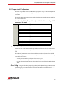
1
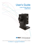
Everything’s possible. BR3410NI-A03-AC120 User Manual Plug-n-Play Servo System with Analog Drive, Brushed Motor and Cables (Continuous 10 lb-in, 4200 rpm) www.a-m-c.com MNQSA3UM-01 BR3410NI-A03-AC120 Thank you for purchasing this QuickStart package! QuickStart makes it easy to set up Advanced Motion Controls drives to get your system running quickly. The drive and motor have been matched with each other, the cables are custom made for this system and an interface board simplifies integration with your controller. Remember, if you need us, we are here for you! Our goal is to get you up and running as quickly as possible. If at any point you have a question, a team of applications engineers and our customer service staff are just a phone call away. We are available weekdays from 8am to 5pm Pacific Time at 805‐389‐1935. We can also be contacted via email through our website www.a‐m‐c.com ‐ go to "Contact Us". 4 Steps to Success! 1 2 3 4 Getting Started 5-Minute QuickStart Integrate QuickStart into Your System Going into Production What’s included with QuickStart and what to expect Let’s spin the motor! Get your machine working. Transitioning from prototype to production. This manual has been laid out in four sections to guide you through the process of setting up and integrating your QuickStart system. By following each step in succession you will first be introduced to QuickStart, then hook up the system for a simple bench test, and then integrate QuickStart into your machine and finally transition into the production stage. MNQSA3UM-01 1 1 Getting Started 1.1 What to Expect What is ’QuickStart’? QuickStart is a system offering including: a drive, a motor, all necessary cables, and an interface board with screw terminal connections ‐ all in one box ready for fast delivery! What purpose does ’QuickStart’ serve? QuickStart is intended to introduce OEMs to Advanced Motion Controls servo drives and provide a positive first experience. Why is Advanced Motion Controls offering a ’QuickStart’ package? We realize that many OEMs today are faced with trying to get their machinery to market using the fastest possible methods. Our solution is to provide a means by which motion control can be quickly proven. How does ’QuickStart’ benefit potential customers? QuickStart is designed to make system prototyping easier to include Advanced Motion Controls' servo drives. The attraction to OEM's is a savings of time, money and the personnel needed to move from conception to production. Upon receipt, everything will plug in and operate within 5 minutes. All systems are initially configured in velocity or voltage mode to turn the motor shaft at 30 +/‐ 20 rpm. This is an indication that when put together, it works out of the box. No pots to tweak or software to configure! Are 'QuickStart' program motors available for individual resale? Quite simply, not from Advanced Motion Controls. The motors in these packages are meant to represent what is commonly available from many different manufacturers. Your local Advanced Motion Controls representative can handle requests for motor model information for additional purchases. How is ’QuickStart’ pricing important to me? Careful selection of systems incorporate popular Advanced Motion Control's drives in order to maximize exposure and minimize costs. What other considerations should you know about 'QuickStart'? Although it will be hard to find easy‐to‐configure systems like these at lower prices anywhere, QuickStart isn't intended for multiple, pre‐packaged system selling. Initial exposure to Advanced Motion Controls' drives is the key. Each project will be followed up by our Sales department to determine overall progress and assist in determining the next step. MNQSA3UM-01 2 Getting Started / What to Expect 1.1.1 Package Contents Brushed Servo Drive Brushed NEMA 34 Motor Screw Terminal Board Motor Power Cable (10 foot) Drive Power Cable Drive Cable (1.5 foot) Documentation 30A20AC MBR3410NI SIB (System Interface Board) CBL-P03-10 CBL-AC-IEC CBL-D01 Quick Connect Sheet User Manual Brochure 1.1.2 Additional Requirements Item Power Supply Feedback Controller MNQSA3UM-01 Notes Requirements: •120 VAC 60 hz Single Phase •Acceptable Operating Range 30 - 125 VAC Since this package does not come with feedback, an additional encoder or tachometer must be installed for precise position or velocity control. ±10V Command Signal. 3 2 5-Minute QuickStart Let’s Spin the Motor! This quick setup procedure will get the motor moving in a short amount of time without the need for a controller. The drive has been pre‐configured in Voltage Mode with a slight offset. This will turn the motor at a slow steady speed on power‐up to demonstrate operation. Once the system is shown to be operational, the next section ‐ Integrate QuickStart into Your System ‐ will guide you through the process of integrating the system into your application. 2.1 Wiring In Section 2.4, you will find the cables and connections sheet. Use this as a reference when following the steps in this section. 2.1.1 Drive Connect cable CBL‐D01 to the P1 connector on the drive. Connect the other end to the C2 connector on the system interface board (SIB). 2.1.2 Motor Connect the white connector on the motor to the corresponding connector on cable CBL‐P03‐ 10. Connect the red and black wires to the P2 connector on the drive. Black Red Motor 1, P2-1 Motor 2, P2-2 CBL‐AC‐IEC supplies AC to the drive. Do not apply power at this time. An AC power strip or other switch can be used to make cycling power more convenient during testing. MNQSA3UM-01 4 5-Minute QuickStart / Grounding 2.2 Grounding Bring all ground wires to a central point ground such as a ground bus, ground plane or a single ground bolt. Also don't forget to ground the drive chassis! Use the silver screw marked PE on the case. 2.2.1 Motor Ground The green wire coming from the motor power cable is the motor chassis ground. If the motor case is already grounded through direct contact with the machine housing, then leave the green wire disconnected. Grounding the motor at both the green wire and at the motor case causes a ground loop that has been shown to disrupt the feedback signals. Choose one or the other. 2.3 Inhibit Switch (optional for this section) An inhibit switch (not included) can be connected between pins 9 and 11 on the Interface Board. This switch disables power to the motor until you are ready. Opening the switch Enables the drive, closing the switch Disables the drive. To avoid the motor from jumping unexpectedly and causing damage, the motor should be secured either with clamps or bolted down using its mounting holes. MNQSA3UM-01 5 5-Minute QuickStart / Cables and Connections 2.4 Cables and Connections MNQSA3UM-01 6 5-Minute QuickStart / Inhibit Line Test (optional) 2.5 Inhibit Line Test (optional) Follow this step only if you installed the inhibit switch described in Section 2.3. This is to verify that the optional inhibit switch is functioning and the drive is initially powered up in a disabled state. 1. Disconnect the motor power by unplugging the white connector on CBL‐P03‐10. Unplugging this connection allows you to power up the system without the possibility of spinning the motor. 2. Apply power to the drive. Toggle the inhibit switch and verify that you can cause the LED color to change from Red to Green. Set the switch so the LED is Red. 3. Remove power from the drive and reconnect the white connector on CBL‐P03‐10. 2.6 System Power-Up 1. Apply power to the drive. If an inhibit switch has been installed, enable the drive by toggling the inhibit switch so the LED turns Green. 2. The motor should turn at a smooth controlled speed. 3. If the motor turns then the system has been hooked up correctly. Remove power and continue to the next section. If not then go to Troubleshooting. 4. To stop the motor from turning, turn the Test/Offset switch (SW10) to the OFF position. Then use the offset pot (Pot 4) to set the speed to zero. 2.6.1 Troubleshooting LED not lit. Motor doesn't have holding torque LED doesn't turn Green. Verify that power has been applied to the drive. Verify that the LED is Green. Verify all cables are connected. If an Inhibit Switch has been installed, toggle the Inhibit switch. Motor doesn't turn but has holding torque Turn Pot 4 (Test/Offset) in either direction. This will change the amount of offset in the drive. Contact Factory - If you can't get the motor turning within a few minutes, please call and ask for technical support! 805-389-1935. We want to get you up and running quickly! MNQSA3UM-01 7 3 Integrate QuickStart into Your System The following instructions are a continuation of the previous chapter. This section explains controller wiring, drive configuration, drive mounting, motor mounting, SIB mounting and load coupling. 3.1 Wiring 3.1.1 Signal Ground Almost all signals between the drive and the controller are referenced to signal ground. Without this reference, the drive and the controller would not be able to transmit signals to each other. To ensure that the signals between the drive and the controller are referenced to the same potential, the signal grounds on the controller and the drive must be connected together. This is especially important for: • • • Single ended command signals Inhibit line Other inputs and outputs. You will need to identify the signal ground on your controller and connect it to the signal ground on the drive. For your convenience, the Signal Ground is accessible at two locations on the SIB. However, to avoid ground loops there should only be one connection between the drive signal ground and the controller signal ground. Don't add a connection if there is already continuity between the two grounds. Available Signal Ground Locations on the SIB Controller Signal Ground MNQSA3UM-01 SIB C3-2 (SGND) C3-7 (Tach/GND) 8 Integrate QuickStart into Your System / Wiring 3.1.2 Command Signal Command signal and mode selection are dictated by the capabilities of your controller and the desired operation of your system. Analog ±10V command signals are suited for torque and velocity modes. ±10V Command Signal (Single Ended) Signal SGND Command SIB C3-2 (SGND) C3-4 (Ref+) Available Drive Modes Torque Mode, Velocity Mode ±10V Command Signal (Differential) Signal Command + Command - SIB C3-4 (Ref+) C3-5 (Ref-) Available Drive Modes Torque Mode, Velocity Mode More Information on Mode Selection Drive modes can be separated into three basic categories: Torque, Velocity and Position. The name of the mode describes what servo loops are being closed in the drive. They don't describe the end‐result of the operation. For example, a drive in Torque mode can still be in a positioning application if the external controller closes the position loop. In fact, most high performance positioning systems use a drive in torque mode with the controller closing the velocity and position loops. The correct mode is determined by the requirements of the controller. Some controllers require that the drive be in torque mode. Other controllers require that the drive be in velocity mode. Check the documentation on your controller or contact the manufacturer of your controller to determine the correct mode for your drive. Once the command signal and mode have been selected, connect the controller to the signals as indicated in the above tables. The proper gains and command settings must also be configured. This will be explained later in the configuration section. 3.1.3 Drive Inhibit (Recommended) The inhibit line is used to turn off power to the motor while the drive is still powered on. Sometimes this is necessary if power to the motor needs to be removed quickly or if the user needs to manually move the load in a freewheeling condition. If your controller has an inhibit function then we highly recommend that you use it. Inhibit Connection Controller Inhibit SIB C3-11 Inhibit Note that the inhibit input is configured to disable the drive when pulled low (active low). MNQSA3UM-01 9 Integrate QuickStart into Your System / Wiring 3.1.4 Drive Mounting Mounting Dimensions are found in the drive datasheet in the Appendix. The drive can be mounted flat against the base plate or along the spine. Mounting the drive flat on the base plate against a large thermally conductive surface for cooling will provide the most natural heat dissipation for the drive. A metal back plane in a cabinet on the machine often makes a good surface. Drives mounted on the spine can be mounted next to each other. Maintain a minimum separation of 1 inch between drives to provide adequate convection cooling. Additional cooling may be necessary to dissipate the heat generated by the drive depending on ambient temperatures, duty cycle and natural ventilation. Note 3.1.5 Motor Mounting Mounting Dimensions are found in the motor datasheet in the Appendix. The mounting surface must be stiff enough so it does not deflect when radial loads are applied to the motor shaft. The mounting surface should also have good thermal conductivity, especially if peak performance is demanded of the motor. 3.1.6 SIB Mounting Mounting Dimensions can be found in the SIB datasheet in the Appendix. The SIB can be mounted using the mounting holes or a DIN tray such as from Phoenix Contact. If using the mounting holes, standoffs must be used to keep the bottom of the SIB from shorting with the mounting surface. 3.1.7 Cable Routing Cable Datasheets can be found in the Appendix. QuickStart cables come with excellent shielding and make proper grounding easy. This makes proper cable routing less critical, however proper routing practices should still be followed. Route cables to minimize length and minimize exposure to noise sources. The motor power wires are a major source of noise and the motor feedback wires are susceptible to receiving MNQSA3UM-01 10 Integrate QuickStart into Your System / Wiring noise. This is why it is never a good practice to route the motor power wires close to the motor feedback wires even if they are shielded. Although both of these cables originate at the amplifier and terminate at the motor, try to find separate paths that maintain distance between the two. A rule of thumb for the minimum distance between these wires is 1cm for every 1m of cable length. 3.1.8 Grounding Bring all ground wires to a central point ground such as a ground bus, ground plane or a single ground bolt. Also don't forget to ground the drive chassis! Use the silver screw marked PE on the case. Motor Ground The green wire coming from CBL‐P03‐10 is for the motor case ground. If the motor case is already grounded through direct contact with the machine housing, then leave the green wire disconnected. Grounding the motor at both the green wire and at the motor case causes a ground loop that has been shown to disrupt the feedback signals. Choose one or the other. 3.1.9 Load Coupling A non‐rigid coupling must be used between the motor shaft and the load to minimize mechanical stress due to radial loads, axial loads or misalignment. If you feel that the radial load on the motor is excessive, you may want to consider connecting the motor to an idler shaft that is supported by pillow block bearings (or similar). Then the load can be coupled to the idler shaft without risking damage to the motor bearings. MNQSA3UM-01 11 Integrate QuickStart into Your System / Configuration 3.2 Configuration 30A20AC Capabilities Mode Category Torque Velocity Estimation Mode Name Current Voltage* IR Compensation* *Voltage Mode and IR Compensation Mode do not use direct feedback to close the velocity loop; therefore, they can’t be considered a true velocity modes. These modes produce velocity that is roughly proportional to the input command but are not as precise as using a Tachometer or Encoder. The correct mode is determined by the requirements of the controller. Some controllers require that the drive be in torque mode. Other controllers require that the drive be in velocity mode. Check the documentation on your controller or contact the manufacturer of your controller to determine the correct mode for your drive. Advanced Motion Controls Analog Servo Drives are configured using Switches and Potentiometers. There is no software to download or configure. The basic setup of these servo drives is straight‐forward and user‐friendly. These instructions will walk you through the steps necessary to configure your drive to your system: • MNQSA3UM-01 Configure the drive mode. — Torque Mode Configuration — Velocity Mode Configuration ->Voltage ->IR Compensation 12 Integrate QuickStart into Your System / Configuration 3.2.1 Torque Mode Configuration The terms 'Torque Mode' and 'Current Mode' are synonymous. They can be interchanged and you may see either of these terms throughout this document and other motion control documents. The Switches and Potentiometers set the mode on the drive. Use the Mode Selection Table for the correct configuration. Mode Selection Table - Torque Mode (current limit with these settings - 7.5A continuous, 30A peak) Switches Pots SW1 SW2 SW3 SW4 SW5 SW6 SW7 SW8 SW9 SW10 Pot 1 - Loop Gain Pot 2 - Current Limit Pot 3 - Reference Gain Pot 4 - Offset OFF OFF ON OFF ON ON OFF ON OFF OFF Full CCW Full CW Full CW Mid (7 turns) Potentiometer Instructions CW is the clockwise direction, CCW is the counterclockwise direction. Full CW or Full CCW means the pot has been turned to the end of its travel where it begins to click on every turn. These potentiometers have a 14 turn range before they start to click. The number of potentiometer turns on the Mode Selection Table is referenced from the full counterclockwise position. To maintain consistency in the number of turns the initial starting point is defined as follows: 1. Turn the pot CCW until the pot begins to click on every turn. 2. Continue to slowly turn the pot CCW until the next click is heard, then stop. 3. Now turn the pot in the CW direction the number of turns indicated in the Mode Selection Table. Gain Setting The gain of the drive (amps out)/(volts in) can be adjusted using the Reference Gain Potentiometer, Pot 3. Turning the pot to the full clockwise position results in a gain of roughly 3A/V. Turning the pot counter clockwise reduces the gain down to a minimum of zero. MNQSA3UM-01 13 Integrate QuickStart into Your System / Configuration 3.2.2 Velocity Mode Configuration Velocity mode controls the motor such that the motor velocity is proportional to a given input command. The gain can be expressed as (output velocity)/(input command). Common units are (rpm)/(V) and (counts per second)/(V). Since the two velocity modes in this system don’t use direct feedback, their performance isn’t as accurate as as true velocity mode. Voltage Mode This mode does not use any feedback to determine velocity. Velocity is estimated by measuring the voltage across the motor terminals. Since motor voltage is proportional to the speed, the velocity can be controlled. IR Compensation Mode This is the same as Voltage Mode with the addition of positive current feedback into the voltage loop. IR compensation improves on Voltage Mode performance by enabling the amplifier to react to disturbances on the motor shaft. When the shaft is stalled, the back emf naturally drops which increases the current into the motor. The increased current (in the form of a voltage signal) is injected back into the voltage loop, which effectively tells the motor to further increase the output and maintain velocity. The disadvantage of this mode is the use of positive feedback that tends to make this mode more unstable and difficult to tune. The Switches and Potentiometers set the mode on the drive. Use the Mode Selection Table for the correct configuration. Mode Selection Table - Voltage Mode (current limit with these settings 7.5A continuous, 30A peak) Voltage Switches Pots SW1 SW2 SW3 SW4 SW5 SW6 SW7 SW8 SW9 SW10 Pot 1 - Loop Gain Pot 2 - Current Limit Pot 3 - Reference Gain Pot 4 - Offset ON OFF ON OFF ON OFF OFF OFF OFF OFF 10.5 turns Full CW Full CW Mid (7 turns) IR Comp ON ON ON OFF ON OFF OFF OFF OFF OFF 10.5 turns Full CW Full CW Mid (7 turns) Potentiometer Instructions CW is the clockwise direction, CCW is the counterclockwise direction. Full CW or Full CCW means the pot has been turned to the end of its travel where it begins to click on every turn. These potentiometers have a 14 turn range before they start to click. MNQSA3UM-01 14 Integrate QuickStart into Your System / Configuration The number of potentiometer turns on the Mode Selection Table is referenced from the full counterclockwise position. To maintain consistency in the number of turns the initial starting point is defined as follows: 1. Turn the pot CCW until the pot begins to click on every turn. 2. Continue to slowly turn the pot CCW until the next click is heard, then stop. 3. Now turn the pot in the CW direction the number of turns indicated in the Mode Selection Table. Loop Gain - Potentiometer 1 In Velocity Mode the loop gain increases the responsiveness of the system. The loop gain settings in the mode selection table are a good starting point. However, once the drive is in the system, the loop gain will need to be adjusted to match the system dynamics. To adjust the Loop Gain: • • • • • Turn the Loop Gain pot to the full counterclockwise position. Enable the drive Turn the Loop Gain pot clockwise. When the system begins to make a loud buzzing noise, turn the pot in the counterclockwise direction until the buzzing stops. Turn the pot one more turn in the counter clockwise position. Reference Gain - Potentiometer 3 The gain of the drive (velocity out)/(volts in) can be adjusted using the Reference Gain Potentiometer, Pot 3. Turning the pot clockwise increases the gain, while turning the pot counter clockwise decreases the gain. MNQSA3UM-01 15 4 Going into Production 4.1 Prototype to Production Once you have completed your proof of concept you will be ready to design for production. If you decide that the QuickStart drive and motor are perfect for you then you're in luck. Both are popular off‐the‐shelf items that are readily available. Drives can be ordered directly from us and we can put you in touch with the appropriate motor supplier. If your servo system requires a drive that better fits your application such as: • • • • • Additional features Different power range Smaller size Different form factor such as 'plug in' style drives Network connectivity Then our applications engineers can help optimize your system by selecting the best drive for your needs. You will also be in contact with a local representative to help you with the selection of motors and other system components such as cables, gear boxes, slides, bearings and more. Feedback Your feedback is important to us. Your comments can make QuickStart better and help us improve our processes, technical support, customer support and product offering. Please go here to provide us your feedback. MNQSA3UM-01 16 Going into Production / Prototype to Production This page intentionally left blank MNQSA3UM-01 17 Appendix A. System Specifications B. Drive Datasheet C. Motor Datasheet D. Cable Datasheets E. System Interface Board MNQSA3UM-01 18 / This page intentionally left blank MNQSA3UM-01 19 A System Specifications A.1 System Specifications Torque - peak Torque - continuous Velocity Maximum Supply Voltage Speed Torque Curve MNQSA3UM-01 46.8 lb-in, 5.27 Nm 10.6 lb-in, 1.2 Nm 4200 rpm 120 VAC 20 / System Specifications This page intentionally left blank MNQSA3UM-01 21 Analog Servo Drive Description 30A20AC Power Range The 30A20AC PWM servo drive is designed to drive brush type DC motors at a high switching frequency. A single red/green LED indicates operating status. The drive is fully protected against over-voltage, under voltage, over-current, over-heating and short-circuits across motor, ground and power leads. Furthermore, the drive can interface with digital controllers or be used as a stand-alone system. The drive requires only a single AC power supply. Loop gain, current limit, input gain and offset can be adjusted using 14-turn potentiometers. The offset adjusting potentiometer can also be used as an on-board input signal for testing purposes. Peak Current 30 A Continuous Current 15 A Supply Voltage 45 - 140 VAC Features Optical Isolation Between High & Low Power Signals On-Board Test Potentiometer Four Quadrant Regenerative Operation Adjustable Input Gain DIP Switch Selectable Modes Drive Status LED Adjustable Current Limits Directional Inhibit Inputs for Limit Switches High Switching Frequency Built-in brake/shunt regulator Differential Input Command Internal brake/shunt resistor Offset Adjustment Potentiometer Built in Shunt Regulator Circuit MODES OF OPERATION Current Voltage IR Compensation Velocity COMMAND SOURCE ±10 V Analog Release Date: 3/2/2010 Revision: 2.01 FEEDBACK SUPPORTED Tachometer (±60 VDC) ±10 VDC Position COMPLIANCES & AGENCY APPROVALS UL cUL CE Class A (LVD) CE Class A (EMC) RoHS Advanced Motion Controls · 3805 Calle Tecate, Camarillo, CA, 93012 ph# 805-389-1935 · fx# 805-389-1165· www.a-m-c.com Page 1 of 9 Analog Servo Drive 30A20AC BLOCK DIAGRAM Information on Approvals and Compliances US and Canadian safety compliance with UL 508c, the industrial standard for power conversion electronics. UL registered under file number E140173. Note that machine components compliant with UL are considered UL registered as opposed to UL listed as would be the case for commercial products. Compliant with European CE for both the Class A EMC Directive 2004/108/EC on Electromagnetic Compatibility (specifically EN 61000-6-4:2007 and EN 61000-6-2:2005) and LVD requirements of directive 2006/95/EC (specifically EN 60204-1:2006), a low voltage directive to protect users from electrical shock. RoHS (Reduction of Hazardous Substances) is intended to prevent hazardous substances such as lead from being manufactured in electrical and electronic equipment. Release Date: 11/30/2011 Revision: 2.01 ADVANCED Motion Controls · 3805 Calle Tecate, Camarillo, CA, 93012 ph# 805-389-1935 · fx# 805-389-1165· www.a-m-c.com Page 2 of 9 Analog Servo Drive 30A20AC SPECIFICATIONS Power Specifications Units Description AC Supply Voltage Range VAC 45 - 140 DC Supply Voltage Range VDC 40 - 190 DC Bus Over Voltage Limit VDC 195 Maximum Peak Output Current1 A 30 Maximum Continuous Output Current A 15 Maximum Continuous Output Power at Continuous Current W 2707 Internal Bus Capacitance µF 3600 Internal Shunt Resistance Ω 10 Internal Shunt Resistor Power Rating W 50 VDC 185 Minimum Load Inductance (Line-To-Line)2 µH 250 Switching Frequency kHz 22 Shunt Fuse A 3 Bus Fuse A 16 Internal Shunt Resistor Turn-on Voltage Description Command Sources Control Specifications Units - Value Value ±10 V Analog Feedback Supported - ±10 VDC Position, Tachometer (±60 VDC) Commutation Methods - Brush Type Modes of Operation - Current, IR Compensation, Velocity, Voltage Motors Supported - Single Phase (Brushed, Voice Coil, Inductive Load) Hardware Protection - Over Current, Over Temperature, Over Voltage, Short Circuit (Phase-Phase & Phase-Ground) Primary I/O Logic Level - 5V TTL Internal Shunt Regulator - Yes - Yes Internal Shunt Resistor Description Agency Approvals Mechanical Specifications Units - Size (H x W x D) mm (in) Value CE Class A (EMC), CE Class A (LVD), cUL, RoHS, UL 186.7 x 107.4 x 62.2 (7.4 x 4.2 x 2.4) Weight g (oz) Heatsink (Base) Temperature Range3 °C (°F) 1140 (40.2) 0 - 65 (32 - 149) Storage Temperature Range °C (°F) -40 - 85 (-40 - 185) Form Factor - Panel Mount P1 Connector - 16-pin, 2.54 mm spaced, friction lock header P2 Connector - 2-contact, 11.10 mm spaced, tri-barrier terminal block Notes 1. 2. 3. Maximum duration of peak current is ~2 seconds. Lower inductance is acceptable for bus voltages well below maximum. Use external inductance to meet requirements. Additional cooling and/or heatsink may be required to achieve rated performance. Release Date: 3/2/2010 Revision: 2.01 Advanced Motion Controls · 3805 Calle Tecate, Camarillo, CA, 93012 ph# 805-389-1935 · fx# 805-389-1165· www.a-m-c.com Page 3 of 9 Analog Servo Drive 30A20AC PIN FUNCTIONS P1 - Signal Connector Pin Name 1 2 3 4 5 6 7 +10V 3mA OUT SIGNAL GND -10V 3mA OUT +REF IN -REF IN -TACH IN +TACH / GND 8 CURR MONITOR OUT 9 CURRENT REF OUT 10 NC 11 INHIBIT IN 12 13 +INHIBIT IN -INHIBIT IN 14 FAULT OUT 15 16 NC NON-ISO GND Description / Notes ±10 V @ 3 mA low power supply for customer use. Short circuit protected. Reference ground common with signal ground. Differential Reference Input (±10 V Operating Range, ±15 V Maximum Input) Negative Tachometer Input (Maximum ±60 V). Use signal ground for positive input. Positive Tachometer Input and Signal Ground Current Monitor. Analog output signal proportional to the actual current output. Scaling is 7.7 A/V by default but may be reduced to half this value by setting DIP switch SW-5 to OFF (see Hardware Settings section below). Measure relative to power ground. Measures the command signal to the internal current-loop. This pin has a maximum output of ±7.25 V when the drive outputs maximum peak current. Measure relative to signal ground. Not Connected (Reserved) TTL level (+5 V) inhibit/enable input. Leave open to enable drive. Pull to ground to inhibit drive. Inhibit turns off all power devices. Positive Direction Inhibit (Does Not Cause A Fault Condition) Negative Direction Inhibit (Does Not Cause A Fault Condition) TTL level (+5 V) output becomes high when power devices are disabled due to at least one of the following conditions: inhibit, output short circuit, over voltage, over temperature, power-up reset. Not Connected (Reserved) Connected to power ground and can be used as a reference point for P1-8 and P1-9. I/O O SGND O I I I SGND O O I I I O PGND P2 - Motor Power Connector Pin 1 2 Name -MOT +MOT Release Date: 3/2/2010 Description / Notes Negative Motor Output Positive Motor Output Revision: 2.01 Advanced Motion Controls · 3805 Calle Tecate, Camarillo, CA, 93012 ph# 805-389-1935 · fx# 805-389-1165· www.a-m-c.com I/O O O Page 4 of 9 Analog Servo Drive 30A20AC HARDWARE SETTINGS Switch Functions Switch 1 2 3 4 5 6 7 8 9 10 Setting Description Voltage feedback. Mode dependent (see mode selection table below). IR compensation. Activates or deactivates IR feedback. ON for IR compensation mode and OFF for other modes. Current loop proportional gain adjustment. ON by default. Inner (current) loop integral gain adjustment. OFF by default. Current scaling. When OFF, increases sensitivity of current sense thus reducing both peak and continuous current limit by 50%. The scaling of the current monitor output signal becomes ½ its ordinary value when this switch is OFF. Current limit ratio. Used to set continuous-to-peak current limit ratio. Default is OFF. Current loop integral gain. Activates or deactivates integration. OFF by default. Outer loop integration. Activates or deactivates integration. ON, by default, for current mode and OFF for other modes. Outer loop integral gain adjustment. It is recommended to leave this switch OFF for most applications. Test/Offset. Switches the function of the Test/Offset pot between an on-board command input for testing or a command offset adjustment. OFF by default. On Off On Off On Off Decrease Decrease Increase Increase Full-current Half-current Cont./Peak Ratio = 25% Cont./Peak Ratio = 50% Inactive Active Inactive Active Decrease Increase Test Offset Mode Selection Table Mode SW1 CURRENT OFF VOLTAGE ON IR COMPENSATION ON TACHOMETER OFF Note: SW7 should be off for most applications SW2 SW3 SW4 SW7 SW8 SW9 OFF OFF ON OFF ON ON ON ON OFF OFF OFF OFF OFF OFF OFF OFF ON OFF OFF OFF OFF OFF OFF OFF Potentiometer Functions Potentiometer Description Turning CW Loop gain adjustment for voltage/velocity modes. Turn this pot 1 Increases gain fully CCW in current mode. Current limit. It adjusts both continuous and peak current limit 2 Increases limit while maintaining their ratio. Reference gain. Adjusts the ratio between input signal and output 3 Increases gain variables (voltage, current, or velocity). Offset / Test. Used to adjust any imbalance in the input signal or in 4 the amplifier. Can also be used as an on-board signal source for Adjusts offset in negative direction testing purposes. Note: Potentiometers are approximately linear and have 12 active turns with 1 inactive turn on each end. Release Date: 3/2/2010 Revision: 2.01 Advanced Motion Controls · 3805 Calle Tecate, Camarillo, CA, 93012 ph# 805-389-1935 · fx# 805-389-1165· www.a-m-c.com Page 5 of 9 Analog Servo Drive 30A20AC Through-hole Components† Location Description Velocity Loop Integrator. Through-hole capacitor that can be added for more precise velocity loop tuning. See section below on Tuning with Through-hole components for more details. Current Loop Integrator. Through-hole capacitor that can be added for more precise current loop tuning. See section below on Tuning with Through-hole components for more details. Current Loop Proportional Gain. Through-hole resistor that can be added for more precise current loop tuning. See section below on Tuning with Through-hole components for more details. Tachometer Input Scaling. Through-hole resistor that can be added to change the gain of the tachometer input. See section below on Tachometer Gain for more details. IR Compensation Scaling. Through-hole resistor that can be added to configure the amplifier for IR Compensation mode. See section below on IR Compensation Notes for more details. C72* C73* R28* R77* R8* Tuning With Through-hole Components In general, the drive will not need to be further tuned with through-hole components. However, for applications requiring more precise tuning than what is offered by the potentiometers and dipswitches, the drive can be manually modified with through-hole resistors and capacitors as denoted in the above table. By default, the through-hole locations are not populated when the drive is shipped. Before attempting to add through-hole components to the board, consult the section on loop tuning in the installation notes on the manufacturer’s website. Some general rules of thumb to follow when adding through-hole components are: • A larger resistor value will increase the proportional gain, and therefore create a faster response time. • A larger capacitor value will increase the integration time, and therefore create a slower response time. Proper tuning using the through-hole components will require careful observation of the loop response on a digital oscilloscope to find the optimal through-hole component values for the specific application. Tachometer Gain Some applications may require an increase in the gain of the tachometer input signal. This occurrence will be most common in designs where the tachometer input has a low voltage to RPM scaling ratio. The drive offers a through-hole location listed in the above table where a resistor can be added to increase the tachometer gain. Use the drive’s block diagram to determine an appropriate resistor value. IR Compensation Notes For applications that will use IR Compensation mode, a resistor can be added to the location named in the table above. The combination of the added resistor and correct dipswitch settings will configure the amplifier for IR Compensation mode. While in IR Compensation mode, the amplifier will adjust the duty cycle to compensate for changes in the output current. Consult the amplifier’s functional block diagram and the manufacturer’s website for more information. † Note: Damage done to the drive while performing these modifications will void the warranty. Release Date: 3/2/2010 Revision: 2.01 Advanced Motion Controls · 3805 Calle Tecate, Camarillo, CA, 93012 ph# 805-389-1935 · fx# 805-389-1165· www.a-m-c.com Page 6 of 9 Analog Servo Drive 30A20AC MECHANICAL INFORMATION P1 - Signal Connector Connector Information Details Included with Drive Mating Connector 16-pin, 2.54 mm spaced, friction lock header Molex: P/N 22-01-3167 (connector) and P/N 08-50-0114 (insert terminals) Yes 15 NC 13 -INHIBIT IN 11 INHIBIT IN 9 CURRENT REF OUT 7 +TACH / GND 5 -REF IN 3 -10V 3mA OUT 1 +10V 3mA OUT 8 10 NC 12 +INHIBIT IN 14 FAULT OUT 16 NON-ISO GND 2 SIGNAL GND 4 +REF IN 6 -TACH IN CURR MONITOR OUT P2 - Motor Power Connector Connector Information Mating Connector Details Included with Drive 2-contact, 11.10 mm spaced, tri-barrier terminal block Not applicable Not applicable 2 +MOT 1 Release Date: 3/2/2010 Revision: 2.01 -MOT Advanced Motion Controls · 3805 Calle Tecate, Camarillo, CA, 93012 ph# 805-389-1935 · fx# 805-389-1165· www.a-m-c.com Page 7 of 9 Analog Servo Drive 30A20AC MOUNTING DIMENSIONS Release Date: 3/2/2010 Revision: 2.01 Advanced Motion Controls · 3805 Calle Tecate, Camarillo, CA, 93012 ph# 805-389-1935 · fx# 805-389-1165· www.a-m-c.com Page 8 of 9 Analog Servo Drive 30A20AC PART NUMBERING INFORMATION 30 A 20 AC Additional Options Peak Current Maximum peak current rating in Amps. Revision Assigned a letter (A through Z) by manufacturer. Peak Voltage Power Supply Peak voltage rating scaled 1:10 in Volts. : DC Power Supply AC: AC Power Supply Command Isolation Option : Analog Command DD: PWM Command I: Optical Isolation ADVANCED Motion Controls analog series of servo drives are available in many configurations. All models listed in the selection tables of the website are readily available, standard product offerings. ADVANCED Motion Controls also has the capability to promptly develop and deliver specified products for OEMs with volume requests. Our Applications and Engineering Departments will work closely with your design team through all stages of development in order to provide the best servo drive solution for your system. Equipped with on-site manufacturing for quickturn customs capabilities, ADVANCED Motion Controls utilizes our years of engineering and manufacturing expertise to decrease your costs and time-to-market while increasing system quality and reliability. Examples of Customized Integration of Drive into Motor Housing Mount OEM PCB onto Drive Without Cables Multi-axis Configuration for Compact System Custom PCB and Baseplate for Optimized Footprint RTV/Epoxy Components for High Vibration OEM Specified Connectors for Instant Compatibility OEM Specified Silkscreen for Custom Appearance Increased Thermal Limits for High Temp. Operation Products Integrate OEM Circuitry onto Drive PCB Custom Control Loop Tuned to Motor Characteristics Custom I/O Interface for System Compatibility Preset Switches and Pots to Reduce User Setup Optimized Switching Frequency Ramped Velocity Command for Smooth Acceleration Remove Unused Features to Reduce OEM Cost Application Specific Current and Voltage Limits Feel free to contact Applications Engineering for further information and details. Available Accessories ADVANCED Motion Controls offers a variety of accessories designed to facilitate drive integration into a servo system. Visit www.a-m-c.com to see which accessories will assist with your application design and implementation. Filter Cards To Motor Drive(s) All specifications in this document are subject to change without written notice. Actual product may differ from pictures provided in this document. Release Date: 3/2/2010 Revision: 2.01 Advanced Motion Controls · 3805 Calle Tecate, Camarillo, CA, 93012 ph# 805-389-1935 · fx# 805-389-1165· www.a-m-c.com Page 9 of 9 / System Specifications This page intentionally left blank MNQSA3UM-01 31 Quick Start Motor MBR3410NI BRUSHLESS SERVO MOTOR FEATURES: • • • • • • 3.25 Inch HD NEMA 34 Motor Continuous Torques up to 10.6 lb -in Speeds up to 4200 rpm Voltage Rating up to 90 Vdc 30 Lb Radial Load 1/2" from Front Face Smooth, low cogging Magnetics SPECIFICATIONS: SPECIFICATIONS UNITS VALUE CONTINUOUS TORQUE Nm (lb-in) 1.2 (10.6) PEAK TORQUE Nm (lb -in) 6 (53.1) SPEED @ RATED VOLTAGE RPM 4200 RATED VOLTAGE V dc 90 A 7.6 CONTINUOUS CURRENT PEAK CURRENT A 38.0 TORQUE CONSTANT Nm / A (lb -in / A) 0.1757 (1.56) VOLTAGE CONSTANT V / KRPM 18.4 RESISTANCE ohms 0.68 INDUCTNACE mH 2.35 INERTIA kg-cm² (lb -in-s²) 3.39 (0.003) WEIGHT Kg (lb) 3.99 (8.8) ADVANCED MOTION CONTROLS 3805 Calle Tecate, Camarillo, CA 93012 Tel: (805) 389-1935, Fax: (805) 389-1165 / System Specifications This page intentionally left blank MNQSA3UM-01 33 Quick Start Cable CBL-D01 DRIVE CABLE WIRING SPECIFICATIONS: CABLE: CBL-D01 Common Contact Wiring Scheme Function Wire Color Contact 2 Single Wire SGND black 2 6 Single Wire -TACH IN black/white 6 7 Single Wire +TACH red 7 8 Single Wire Current Monitor red/black 8 9 Single Wire (Variable) blue 9 10 Single Wire* (Variable) blue/white 10 A 11 Single Wire* (Variable) purple 11 16-Pin Molex 12 Single Wire (Variable) purple/white 12 Connector: 13 Single Wire (Variable) orange 13 P/N 22-01-3167 14 Single Wire (Variable) orange/white 14 Terminals: 15 Single Wire (Variable) brown 15 P/N 08-50-0114 16 Single Wire (Variable) brown/white 16 1 +REF OUT yellow 1 Twisted Pair 3 -REF OUT yellow/black 3 4 +REF IN green 4 Twisted Pair 5 -REF IN green/white 5 Shield Shield Shell NOTE: For cables with only twisted pairs, single wires can be paired with other single or unused wires. * Creating a twisted pair from these two wires is recommended for brushless applications. Side 1 Connector Side 2 Connector B 26-Pin AMP (D-SUB) Plug: P/N 748365-1 Housing: P/N 748677-2 Terminals: P/N 748333-4 DIAGRAM: Connector B Connector A Single Wires Single Wires Twisted Pairs Twisted Pairs Grounding Shell 1.5 ft ADVANCED MOTION CONTROLS 3805 Calle Tecate, Camarillo, CA 93012 Tel: (805) 389-1935, Fax: (805) 389-1165 Quick Start Cable CBL-P03-10 POWER CABLE WIRING SPECIFICATIONS: CABLE: CBL-P03-10 Side 1 Connector A (4-Pin AMP) Connector, Terminals: P/N 1-480703-0, P/N 350873-1 Contact 1 2 3 4 Wiring Scheme Single Wire Unused Single Wire Shield Common Function Motor + Motor Shield Side 2 Wire Color red white black grey Contact Crimp Crimp Spade Connector - DIAGRAM: Connector A Single Wires Flying Leads Unused Unused Shield Spade 10 ft ADVANCED MOTION CONTROLS 3805 Calle Tecate, Camarillo, CA 93012 Tel: (805) 389-1935, Fax: (805) 389-1165 E System Interface Board (SIB) Dimensions 72mm x 72mm C1 Connector 15 pin to motor C2 Connector 26 pin to drive C3 Connector 26 pin user interface C3 Pin Functions Pin Function 1 +10V 3mA 2 SGND 3 -10V 3mA 4 +Ref In 5 -Ref in 6 -Tach In 7 +Tach/Gnd 8 Curr Mon Out 9 Curr Ref Out 10 NC 11 Inhibit 12 +Inhibit 13 -Inhibit 14 Fault Out 15 NC 16 Non Iso GND 17 -- 18 -- 19 -- 20 -- 21 -- 22 -- 23 -- 24 -- 25 -- 26 -- MNQSA3UM-01 36