1
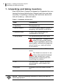
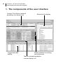
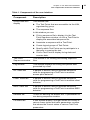
TM
WaveTest™ 802.11
Traffic Generator/
Performance Analyzer
Installation and QuickStart Guide
Version 2.0
January, 2005
Copyright © VeriWave, Inc. All rights reserved
VeriWave, WaveTest, and WaveSuites are trademarks of VeriWave, Inc.
2
About this guide
This guide describes how to install the WaveTest™ 802.11
Traffic Generator/Performance Analyzer and also includes
a brief tutorial showing how to use the system to test an
802.11-compliant device.
Contacting VeriWaveTM Corporate Headquarters
VeriWave™, Inc.
9600 SW Oak Street
Portland, OR 97223
503-473-8350
503-473-8351 (fax)
Address general inquiries to:
[email protected]
Customer Service
503-473-8340 or 1-800-457-5915
[email protected]
Technical Support
503-473-8341 or 1-800-457-5919
[email protected]
Document printing history
Version
Release date
1.0
May, 2004
1.3 (this document)
October 19th, 2004
Conventions used in this guide
WARNING. A warning describes a situation that could
result in the loss of data or damage to equipment.
NOTE. A note contains useful tips.
3
Contents
About this guide 2
Contacting VeriWaveTM Corporate Headquarters 2
Document printing history 2
Conventions used in this guide 2
5
Installing the WaveTest System 5
1. Unpacking and taking inventory 6
2. Preparing the installation site 7
User-provided equipment 7
LAN requirements and recommendations 8
Guidelines for the test environment 8
3. Positioning the Test Points 9
4. Connecting the Test Points 10
5. Installing the WaveTest System software 13
6. Verifying the installation 14
7. Troubleshooting a faulty installation 17
Power cycle the Test Point after each fix 17
Troubleshooting list 17
21
The WaveTest QuickStart 21
8. The components of the user interface 22
9. Creating the test sequence 24
Getting started 24
Defining test environment parameters 24
Programming the Test Point to look for a beacon 25
Programming an active scan 26
Editing sequences files 27
10.Running the test 28
Associating the sequence to the Test Point 28
Starting the test 28
4
11.Examining the results 29
Viewing log files with external tools 29
12.Where to go for additional information 30
CHAPTER 1:
Installing the WaveTest System
This chapter describes how to install all components of the
WaveTest™ Traffic Generator/Performance Analyzer, covering these topics:
X
Unpacking and taking inventory.
X
Preparing the test site.
X
Installing the hardware.
X
Installing the software.
X
Verifying the installation.
X
Troubleshooting a faulty installation.
6
Chapter 1: Installing the WaveTest System
Unpacking and taking inventory
1. Unpacking and taking inventory
Each WaveTestTM System is shipped in a separate box containing the items listed below. Unpack each box and take
inventory. If anything is missing, call customer service at
503-473-8340 or 1-800-457-5915.
Table 1. Contents of each box
Item
Comments
1 Test Point
The physical unit.
1 power adaptor
A universal power adaptor capable of
accepting 100-240VAC at 50-60 Hz.
1 Ethernet cable
10 feet, Cat 5, terminated with
unshielded RJ-45 plugs.
1 timing cable
For synchronizing the Test Points.
The WaveTest TM System is calibrated for the provided timing
cables. If your installation calls for different cables, call technical support at
503-473-8341 (or 1-800-457-5919)
for assistance.
1 antenna
Omni-directional, with an SMA connector.
The Antenna connector is sensitive to electrostatic discharge.
Provide static protection to avoid
damage when connecting and disconnecting the antenna.
1 CD
The WaveTest™ System software,
documentation, and example test
sequences.
This guide
Installation and QuickStart information.
NOTE. Save all packing materials in case you have to
return equipment.
Chapter 1: Installing the WaveTest System
Preparing the installation site
2. Preparing the installation site
User-provided equipment
The following equipment is not provided by VeriWaveTM:
Table 2. User-provided equipment
Equipment
Comment
PC (required)
For running the WaveTestTM System software. The PC should have an Ethernet
interface with TCP/IP networking, a CDROM capable drive, at least 256 MB of
RAM, and at least 50 MB of disk space.
Ethernet LAN
(required)
For communication between the PC and
the Test Points. See “LAN requirements
and recommendations” on page 8.
RF cable (optional)
An RF cable can be used in place of the
antenna to physically link the Test Point
to the device under test. The cable must
be 50 ohm and must be terminated into
50 ohm to achieve the specified performance.
Substitute Ethernet cable (optional)
Use any conforming Ethernet cable.
User-supplied
antenna (optional)
50 ohm SMA, VSWR less than 2:1 at
2.400 GHz.
7
8
Chapter 1: Installing the WaveTest System
Preparing the installation site
LAN requirements and recommendations
X
The PC, the Test Points, and the DHCP server must be
on the same IP subnet — there should not be any routers or bridges between the PC and any of the Test
Points.
X
The LAN segment used by the WaveTestTM System
should be isolated from other LAN traffic by a bridge or
router.
X
A DHCP server must be accessible on the subnet to
provide the Test Point with an IP address.
X
We recommend connecting the PC and all the Test
Points to the same HUB or switch.
Guidelines for the test environment
To ensure continuous error-free operation, follow these
guidelines:
X
Avoid locating the Test Points near heating equipment,
in direct sunlight, or anywhere that would expose them
to excessive heat.
X
Protect the Test Points from condensation or rain.
X
Protect the Test Points from excessive dust.
Chapter 1: Installing the WaveTest System
Positioning the Test Points
3. Positioning the Test Points
Position the Test Points in the test environment following
these guidelines:
X
Position the Test Points relative to the device(s) under
test according to the requirements of the tests.
X
If the Test Points are to interact with each other during
a test, position them close enough to each other so that
they can be daisy-chained together with the timing
cables.
X
If you stack the Test Points, do not stack them over six
high. Leave six inches of clearance above the stack for
air circulation.
Figure 1. Positioning the Test Points
DUT
PC
Test Point
Ethernet
hub or
switch
timing cable
Test Point
9
10
Chapter 1: Installing the WaveTest System
Connecting the Test Points
4. Connecting the Test Points
WARNING. When installing a Test Point, the power connection should always applied last, once all other physical
connections have been established. Similarly, before disconnecting any device from the Test Point, first disconnect
the power. Failure to follow these guidelines could result in
damaged equipment.
WARNING. Avoid accidentally plugging the Ethernet cable
into the Test Point’s timing-cable jacks. Doing so could
introduce an electrical charge that might damage the Test
Point.
1. First connect the Test Point(s) to the LAN.
2. (If your site is using only one Test Point, skip this step.)
Select any Test Point to serve as the first device in the
daisy-chain and connect a timing cable to sync port 1.
Connect the other end of the cable to sync port 2 of the
second device in the chain.
If there is a third Test Point, connect a second timing
cable to port 1 of the second Test Point and connect
the other end to port 2 of the third device. Proceed similarly until all devices are connected.
WARNING. The Test Points are calibrated for the timing
cables provided by VeriWaveTM. Using other cables may
result in faulty test data. If your installation requires
different length cables, contact technical support at
503-473-8341 or 1-800-457-5919.
Chapter 1: Installing the WaveTest System
Connecting the Test Points
Figure 2. Test Point connections
1st Test Point
multi-test point
sync
1
POWER
2
AC
source
timing
to the Ethernet
connect pwr last!
multi-test point
sync
1
2
timing
to the Ethernet
POWER
AC
source
connect pwr last!
to port 1 of the next Test Point
3. Connect an antenna to the SMA connector on the front
panel of each Test Point. For an omni-directional signal
pattern, orient the antenna vertically.
WARNING. The wide bandwidth antenna connection
can be damaged with static discharge. When connecting an antenna or RF cable to the SMA connector, always provide static protection to avoid damage
to the Test Point.
If using an RF cable (not provided) to physically link the
Test Point to the device under test, connect the cable to
the Test Point in place of the antenna and connect the
other end to the device under test.
To cable multiple Test Points to a device under test,
use an RF combiner (not provided). The combiner
should meet the same specifications as the RF cable.
4. Once all other connections have been made, connect
the power adaptor to the Test Point and connect the
power plug to an AC source. The green light on the
11
12
Chapter 1: Installing the WaveTest System
Connecting the Test Points
front panel will indicate the Test Point device is powered.
Chapter 1: Installing the WaveTest System
Installing the WaveTest System software
5. Installing the WaveTest System software
1. Insert the CD in the disk drive. If the installation does
not automatically start, select “Run” on your PC’s Start
menu, and type:
x:\wavetest-version-installer.exe
where “x” is the identifier of the CD-ROM drive and version is the version number of the WaveTestTM System
software.
2
Follow the prompts to complete the installation.
NOTE. There is an option on the WaveTest sub-menu for
uninstalling the software
13
14
Chapter 1: Installing the WaveTest System
Verifying the installation
6. Verifying the installation
Run the provided test sequence on each Test Point to verify the installation:
1. Start the Command and Control application. It will scan
for the Test Points, and after about 30 seconds begin
posting them in the Group/Test Point display. If not all
Test Points are detected, see “Troubleshooting” on
page 17.
2. A test sequence must be “associated” with the Test
Point on which it will run. Select the first Test Point in
the listing, click the Open button and open the file
“TestInstall.vws”. If you used the default install directory, the file is located in:
C:\Program Files\VeriWave WaveTest\veriwave_home\sequences
Figure 3. Associating a test sequence with a Test Point
Select a Test Point...
Select a Test Point
Navigate to
TestInstall.vws
and open it.
Chapter 1: Installing the WaveTest System
Verifying the installation
3. In the group “Default” uncheck the check-boxes next to
each Test Point except the one the sequence will run
on. Next, select the group “Default”. Then click the
Start button.
Figure 4. Running the test sequence
Un-check all but the target Test Point
Select the group “Default”
Click Start
15
16
Chapter 1: Installing the WaveTest System
Verifying the installation
4. When the sequence is done, the Counters windows will
open, but will not display any data. Select the Test
Point to display the data acquired during the run.
If the Test Point is installed correctly, the
“TX Frames” counter will show a value of 10.
Figure 5. Indication of a correctly installed system
Select the Test Point to display the data
“10” in this field indicates all OK
5. Repeat steps 1 through 4 for each Test Point.
Chapter 1: Installing the WaveTest System
Troubleshooting a faulty installation
Troubleshooting a faulty installation
Power cycle the Test Point after each fix
As the last step of any attempted fix, power cycle the Test
Point. A repair will not take affect until the system reboots.
Once power is applied, it takes approximately 30 seconds
for the WaveTestTM System application to scan for the
TestPoint and post it in the user interface.
WARNING. If a repair requires disconnecting a physical
component from the Test Point, always disconnect the
power first. To maximize the life of the power connector on
the back panel of the Test Point, always disconnect power
at the power adaptor or at the AC outlet.
Troubleshooting list
Table 3. Troubleshooting list
Symptom
Cause/Solution
The green
power LED
is off.
The external power supply is disconnected or
has failed:
X Check connections between the Test Point,
external power adapter, and wall outlet.
X Verify that wall outlet is energized with AC
power.
X If you have multiple Test Points, take the
power adaptor of a functioning one and
swap it the power adaptor of the faulty one.
To replace a faulty power adaptor, call customer service at 503-473-8340 or 1-800457-5915.
If the problem persists, call VeriWaveTM technical support at 503-473-8341 or 1-800-4575919.
17
18
Chapter 1: Installing the WaveTest System
Troubleshooting a faulty installation
Table 3. Troubleshooting list (cont.)
Symptom
Cause/Solution
The Link
LED on the
Ethernet
jack is off.
A Test Point is not functioning:
X If the green power indicator is not lit, trou-
bleshoot it as described on page 17.
X If the indicator is lit, power cycle the Test
Point.
The Ethernet cable is disconnected or is defective:
X Check connections between the Test Point
and the Ethernet hub or switch.
X Replace the Ethernet cable.
The Ethernet hub or switch is malfunctioning:
X Check that the Ethernet hub or switch to
which the Test Point is attached is powered
and configured for the correct mode.
X Attach the Test Point directly to the PC via a
cross-over cable and see if the Link LED on
the external jack lights.
No Test
Points are
listed in the
user interface display.
The Test Points are not connected to same
Ethernet LAN segment as the PC running the
WaveTest™ System application:
X Verify the network topology between the
Test Points and the PC.
X Ensure that a router is not interposed
between the Test Points and the PC.
X If a hub or switch is available, connect the
PC and the Test Points to it and connect its
uplink port to the rest of the LAN.
The DHCP server is absent or misconfigured:
X
Verify that the DHCP server is present and
active on the LAN segment.
X Verify that a router is not interposed
between the Test Points and DHCP server.
X Verify that the PC obtains its IP address via
a DHCP server.
X Verify that the DHCP server is associated
with the same IP subnet as the PC.
Chapter 1: Installing the WaveTest System
Troubleshooting a faulty installation
Table 3. Troubleshooting list (cont.)
Symptom
Cause/Solution
A Test Point
is missing
from the listing in the
user interface (but at
least one is
present).
Not all Test Points are connected to same
Ethernet LAN segment:
X Verify the network topology between the
Test Points and the PC.
The DHCP server is misconfigured or does not
have enough free addresses:
X Check the DHCP server connections.
X Disconnect and power down all Test Points,
then re-connect and power up each in turn
to verify that it is detected.
One or more Test Points have malfunctioned:
X Power down all Test Points then power
them on again one at a time.
The WaveTestTM System application or the PC
running it has malfunctioned:
X Exit and restart the WaveTestTM System
application.
X Exit the WaveTestTM System application,
restart the computer, then restart the
WaveTestTM System application.
Errors in the
test results.
A Test Point has malfunctioned:
X
X
Check cables and connections.
Verify that the SMA RF connector on the
Test Point is connected to either an antenna
or a 50 ohm load (e.g., a device under test
or a power combiner).
X Verify that the power adapter is functioning.
The WaveTestTM System application or the PC
running it has malfunctioned:
X
Exit and restart the WaveTestTM System
application.
X
Exit the WaveTestTM System application,
restart the computer, then restart the
WaveTestTM System application.
19
20
Chapter 1: Installing the WaveTest System
Troubleshooting a faulty installation
CHAPTER 2:
The WaveTest QuickStart
In this chapter you will familiarize yourself with the
WaveTest™ 802.11 Traffic Generator/Performance Analyzer by:
X
Familiarizing yourself with components of the WaveTest™ Command and Control user interface.
X
Creating a test sequence.
X
Running the test sequence.
X
Examining the results in the log file.
If you have a functioning access point at the test site you
can include its parameters in the test sequence. If not, you
can use dummy values (this will result in less data in the
log).
22
Chapter 2: The WaveTest QuickStart
The components of the user interface
1. The components of the user interface
Listing of Test Points, testpoint
groupings, and sequences
Logged test data
display
Sequence file display
Button palettes for building
test sequences
Tabs for accessing palettes,
counter display, etc.
Chapter 2: The WaveTest QuickStart
The components of the user interface
Table 1. Components of the user interface
Component
Description
Group/TestPoint
display
This window lists:
X The Test Points that are accessible via the LAN,
organized by group.
X The sequence files.
In this window you can:
X Click a sequence file to display it in the Test
Point Sequence window, or click a Test Point to
display the associated sequence file.
X Associate a sequence with a Test Point.
X Create logical groups of Test Points.
X Specify which Test Points are to participate in a
test prior to running the test.
X Click a Test Point to display its log data and
counter data.
Test Point
Sequence window
This window is for viewing and editing sequence
files.
Log window
This window displays the timing and packet data
generated by a test.
AP Traffic tab
A palette of buttons used to generate sequence
code for programming a Test Point to emulate
access point behavior.
Client Traffic tab
A palette of buttons used to generate sequence
code for programming a Test Point to emulate client
behavior.
IBSS Traffic tab
A palette of buttons used to generate sequence
code for programming a Test Point to emulate IBSS
behavior.
Defaults tab
A form for defining the default 802.11 parameters to
use during sequence creation.
Counters tab
A two window display, one that shows the counts of
various frame types and traffic parameters, another
that shows the current status of various Test Point
parameters.
23
24
Chapter 2: The WaveTest QuickStart
Creating the test sequence
2. Creating the test sequence
Put in the simplest terms, a sequence is code that programs a Test Point to:
X
Transmit specific 802.11-compliant frames.
X
Wait for the reception of a specific 802.11-compliant
frame and then initiate an action, such as transmitting a
frame or turning on logging.
Depending on the sequence code, the Test Point can be
made to emulate a client, an access point, or any device
designed to transmit and/or receive 802.11-compliant
frames.
In this example you will create a sequence that programs
the Test Point to perform rudimentary client-type behavior.
When the sequence is run, the Test Point will:
X
Look for a beacon.
X
Issue a probe request.
Getting started
1. Start the WaveTest™ System using the desktop icon or
the start menu.
2. In the Group/TestPoints display, select “Sequences”,
then click the New button located under the Test Point
Sequence window.
A new sequence “seq1” is added to the listing in the
Group/TestPoints display.
3. Click the Client Traffic tab to access a palette of buttons for programming a Test Point for client-type
behavior.
Defining test environment parameters
Every sequence starts with definitions of the parameters of
the test environment. In this sequence you will define are a
channel, a data rate, and the MAC addresses of devices
participating in the test.
1. Click the Channel button and specify the channel on
which the access point is transmitting. If there is no
functioning access point at the site, leave the channel
setting as is.
Chapter 2: The WaveTest QuickStart
Creating the test sequence
2. Click the Data Rate button and specify 1 Mb/s.
3. Click the Address button to specify the Test Point’s
MAC address:
X For
address name enter “ClientTP1”.
X For
address value enter “00:00:11:22:33:44”.
4. Click the Address button to specify the AP’s MAC
address. Even if there is no functioning access point at
the site you need to define a name and address to use
in the sequence:
X For
address name enter “AP1”.
X For
address value enter the MAC address of the AP.
If no access point is present, enter the dummy value
“00:01:02:03:04:05”.
Programming the Test Point to look for a beacon
Now that the environment is defined it is time to code the
first action in the test – looking for a beacon frame.
To do this you will insert a “Wait for Frame” command in the
sequence. This command programs the Test Point to wait
for the reception of a beacon frame before executing the
next instruction in the sequence. You will specify a time-out
to prevent the test from hanging in the event a beacon
never arrives. To insert the command:
1. Click the Wait for Frame button. In the dialog box that
opens, set four fields as follows:
X Double-click
in the frame control field. A second dialog box opens. Set the Type/SubType field to “Management/Beacon” and click OK to close the dialog
box.
X For
address 1 specify “ba_addr”. Address 1 in a beacon frame is the destination address, which is always
ff:ff:ff:ff:ff:ff (broadcast type). The built-in constant
ba_addr has an assigned value of ff:ff:ff:ff:ff:ff.
X For
time-out specify 1000000 uSec. If the beacon
frame arrives before the time-out, the next command
in the sequence is executed. Otherwise, execution
jumps to a point in the code identified by a label.
X
For goto label, enter “start probe”.
Leave all other fields unchanged and click OK.
25
26
Chapter 2: The WaveTest QuickStart
Creating the test sequence
Programming an active scan
Next you will program the Test Point to perform an active
scan. A successful active scan comprises two operations:
the client transmits a probe request; the client receives the
probe response.
To program the Test Point to perform these two operations
you will insert a “Probe Request” command and a “Wait for
Frame” command to the sequence file:
1. First insert the label referenced in the previous “Wait
for Frame” command — click the Label button and for
Label Name enter “start probe”.
2. Next insert the probe request. Click the Probe
Request button, and set the following three fields:
X For
DA (destination address), specify “ba_addr”
(broadcast).
X For
SA (source address), specify “ClientTP1”.
X For
BSSID, specify “ba_addr”.
Leave all other fields unchanged and click OK.
3. Now insert a “Wait for Frame” command. This command will program the Test Point to look for a frame
that has these two characteristics: it is of type “Probe
Response”; and it has the Test Point as its destination
address.
Click the Wait for Frame button and set the following
four fields:
X Double-click
in the frame control field. A second dialog box opens. For Type/SubType specify
“Management/Probe Response”. Click OK to close
the dialog box.
X For
address 1 (the destination address) specify
“ClientTP1”.
X For
X
the time-out value specify 1000000 uSec.
For go-to label, enter “end test”.
Leave all other fields unchanged and click OK.
4.
Click the Label button and for label name specify “end
test”.
5. Click the EOT button and then click OK. This inserts
the last line in the sequence.
Chapter 2: The WaveTest QuickStart
Creating the test sequence
6. Now save the sequence. In the Group/TestPoint display, select the sequence “seq1” then click the Save
option in the File menu to open the dialog box; enter
“Test1” in the Selection field and click OK. In the
sequence listing, “seq1” changes to “Test1”. Though it
does not show in the listing, the extension “.vws” has
been appended to the file name. The sequence file is
now complete.
Editing sequences files
The WaveTest™ Command and Control user interface has
various tools that simplify editing sequence file:
X
Copy, cut, or delete by selecting a line (press Cntrl or
Shift to select multiple lines), then right-clicking to open
a menu for copying, cutting, or deleting.
X
Paste copied or cut lines by selecting the line preceding the insert point, then right clicking to open a menu
for pasting.
X
Modify a line by double clicking the line; this opens a
dialog box for change the line’s parameters.
X
Add a new line by selecting the line preceding the
insert point and clicking a command button.
X
View different files in the sequence window by clicking
the file name in the Group/Test Point display (or click a
Test Point to open its associated sequence file).
27
28
Chapter 2: The WaveTest QuickStart
Running the test
3. Running the test
To run test, the sequence must be “associated” with the
Test Point that is conducting the test.
Associating the sequence to the Test Point
If this is a new installation and all of the Test Points are
accessible by the host PC over the Ethernet link, each Test
Point will be listed in Group/Test Point display under a
group named “Default”. If there is only one Test Point
installed at your site, it will be the only one listed.
1. First select “Test1” in the Sequences listing of the
Group/Test Point display; right-click to open the pop-up
menu; then select Copy for File Link.
2. Select any Test Point in the group “Default”; right-click
to open the pop-up menu; then select Paste File Link.
“Test1” will appear in the listing next to the Test Point
indicating the operation was successful.
Starting the test
To run the example test:
1. If there are any other Test Points listed as members of
“Default”, uncheck their check boxes.
2. Click the group name “Default” — the Start button
located below the Group/Test Point window will
become active.
3. Click the Start button.
In the listing the Test Point’s status changes from “Stopped”
to “Loading” to “Running”, then back to “Loading”. When
the test completes, the status returns to “Stopped”.
Chapter 2: The WaveTest QuickStart
Examining the results
4. Examining the results
1. If the Traffic Counters window is not visible, click the
Counters tab, then select the Test Point to display the
test data in the window:
X It
should show that 1 frame was transmitted.
X It
may show that any number of frames have been
received depending on the 802.11 traffic in the test
environment.
2. Look in Log Window:
X If
a functioning access point was present in the test
environment, a log entry will indicate that the Test
Point detected a beacon.
X Look
for an entry with a value of “TX” in the RX/TX
column. This is the transmitted probe request. If a
functioning access point was present in the test environment, an entry for the probe response should follow the entry for the probe request.
Viewing log files with external tools
The contents of the log are available in text format for viewing with external editor, and in PCAP format for viewing
with Ethereal or a similar third-party protocol analysis tool.
The files are located in:
c:\Program Files\Veriwave WaveTest\veriwave_home\log_win32
and are identified by the MAC address of the Test Point as
follows:
mac_address.log (text format)
mac_address.cap (PCAP format).
29
30
Chapter 2: The WaveTest QuickStart
Where to go for additional information
Where to go for additional information
The following resources are available for learning more
about the WaveTest™ 802.11 Traffic Generator/Performance Analyzer:
Table 2. Learning more about the WaveTest™ System
Resource
Where to find it
The WaveTest™
User’s Manual
X On the CD shipped with the
WaveTest™ System.
X The Customer section of
www.veriwave.com for the most
recent version.
The Sequence
Command
Reference
X On the CD shipped with the
WaveTest™ System.
X The Customers section of
www.veriwave.com for the most
recent version.
Frequently Asked
Questions
X The Customers section of
Web problem
reporting
X The Customers section of
Technical Support
For returns or answers to technical
questions:
www.veriwave.com.
www.veriwave.com.
X Phone: 503-473-8341 or 1-800-
457-5919.
X Email: [email protected].
Customer Service
For help with ordering:
X Phone: 503-473-8340
or 1-800-457-5915.
X Email:
[email protected].