1
Xciter
user manual
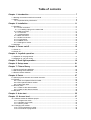
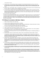
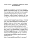
Measurements are in millimeters:
483
188
265
468
35
120
85
© 2003 Martin Professional A/S, Denmark.
Printed in Denmark
This user manual has been developed by R&D International NV, Belgium on behalf of Martin Professional A/S,
Denmark.
All rights reserved. No part of this manual may be reproduced, in any form or by any means, without permission in
writing from Martin Professional A/S, Denmark.
The information contained in this document is subject to change without notice. Martin Professional AS makes no
warranty of any kind with regard to this material, including, but not limited to, the implied warranties of fitness for a
particular purpose.
Martin Profession AS shall not be liable for errors contained herein or for incidental or consequential damages in
connection with the furnishing, performance or use of this material.
P/N 35000119 Revision C
Table of contents
Chapter 1. Introduction ............................................................................................ 7
1.1 Naming conventions used in this manual................................................................................... 7
1.2 Safety ......................................................................................................................................... 8
1.2.1 Important safety instructions ............................................................................................. 8
Chapter 2. Installation ............................................................................................ 11
2.1 Hardware .................................................................................................................................. 11
2.1.1 Power connection............................................................................................................ 11
2.1.1.1 Installing a plug on the mains lead............................................................................ 11
2.1.2 DMX connection .............................................................................................................. 11
2.1.2.1 Devices...................................................................................................................... 12
2.1.2.2 Master/slave .............................................................................................................. 12
2.1.3 MIDI connection .............................................................................................................. 12
2.1.4 AUDIO connection........................................................................................................... 12
2.1.5 I²C expansion .................................................................................................................. 13
2.1.6 USB link to PC................................................................................................................. 13
2.1.7 Desk light or LittLite......................................................................................................... 13
2.2 Software ................................................................................................................................... 13
Chapter 3. Power on/off.......................................................................................... 15
3.1 Power on .................................................................................................................................. 15
3.2 Power off .................................................................................................................................. 15
Chapter 4. Joystick operation................................................................................ 17
4.1 Operation in the programmer ................................................................................................... 17
4.2 Operation in cue (run mode) .................................................................................................... 17
Chapter 5. Desk light operation............................................................................. 19
Chapter 6. Setup menu........................................................................................... 21
Chapter 7. Fixture library ....................................................................................... 23
7.1 Create a new fixture definition.................................................................................................. 23
7.2 Edit existing fixture definition.................................................................................................... 25
7.3 Remove fixture definition.......................................................................................................... 26
Chapter 8. Patch ..................................................................................................... 27
8.1 About physical channels and control channels ........................................................................ 27
8.2 Fixtures..................................................................................................................................... 27
8.2.1 Patch an unpatched fixture number ................................................................................ 28
8.2.2 Edit a patched fixture number ......................................................................................... 30
8.2.3 Clear patch data .............................................................................................................. 30
8.3 Dimmer patch ........................................................................................................................... 31
8.3.1 Create or edit dimmer labels. .......................................................................................... 31
8.3.2 Create or edit dimmer devices ........................................................................................ 32
8.4 DA patch................................................................................................................................... 33
Chapter 9. Auto start .............................................................................................. 35
Chapter 10. Access level........................................................................................ 37
10.1 Different modes for different people ....................................................................................... 37
10.1.1 Programmer mode ........................................................................................................ 37
10.1.2 Operator (run) mode...................................................................................................... 37
10.1.3 Dummy mode ................................................................................................................ 37
10.2 Changing user modes ............................................................................................................ 37
10.2.1 From programmer to other ............................................................................................ 37
10.2.2 From other to programmer ............................................................................................ 38
Chapter 11. File manager........................................................................................ 39
11.1 Defrag ..................................................................................................................................... 39
11.2 Delete show & delete all ......................................................................................................... 39
Chapter 12. Advanced setup .................................................................................. 41
12.1 DMX Config ............................................................................................................................ 41
12.2 MIDI ........................................................................................................................................ 42
Chapter 13. Joystick calibration ............................................................................ 43
Chapter 14. Test ...................................................................................................... 45
Chapter 15. The Xciter philosophy ........................................................................ 47
15.1 Building blocks........................................................................................................................ 47
15.1.1 Scene............................................................................................................................. 47
15.1.2 Sequence ...................................................................................................................... 47
15.2 Show elements ....................................................................................................................... 48
15.2.1 Cue ................................................................................................................................ 48
15.2.2 Playback ........................................................................................................................ 48
15.2.3 Cue list........................................................................................................................... 49
15.3 Programming aids................................................................................................................... 49
15.3.1 Effect generator ............................................................................................................. 49
15.3.2 Preset ............................................................................................................................ 50
15.4 Process priority ....................................................................................................................... 50
Chapter 16. Program features ................................................................................ 51
16.1 Select/deselect device ............................................................................................................ 51
16.2 Select/deselect range ............................................................................................................. 51
16.3 Selection behavior .................................................................................................................. 51
16.3.1 Inclusive......................................................................................................................... 51
16.3.2 Exclusive........................................................................................................................ 51
16.4 Device groups......................................................................................................................... 52
16.5 Fixture information .................................................................................................................. 52
16.6 The programmer ..................................................................................................................... 52
16.6.1 Active versus transparent channels .............................................................................. 52
16.6.2 Handling control channels ............................................................................................. 52
16.6.3 Channel status indicators .............................................................................................. 53
16.6.4 The active and inactive layer of the programmer .......................................................... 53
16.6.5 Presets........................................................................................................................... 54
16.7 Scene / sequence editor ......................................................................................................... 54
16.7.1 Toggle DMX / percentage display ................................................................................. 55
16.7.2 Insert and add scenes ................................................................................................... 55
16.7.3 Modify scene and fade time........................................................................................... 56
16.7.4 Fade curve..................................................................................................................... 57
16.7.5 Preview sequence ......................................................................................................... 58
16.7.6 Lamp procedures........................................................................................................... 58
16.7.7 Invert.............................................................................................................................. 58
16.7.8 Pan / Tilt modifiers......................................................................................................... 59
16.7.9 Copy-paste scene.......................................................................................................... 59
16.7.10 Effects.......................................................................................................................... 59
Chapter 17. Effect generator examples ................................................................. 61
17.1 How to create a circle ............................................................................................................. 61
17.2 How to create a dimmer chase............................................................................................... 62
17.3 How to create a color chase ................................................................................................... 63
17.4 How to use the modulating generators (generators 1-5)........................................................ 63
17.5 How to use the BPM generators (generators 251-255).......................................................... 64
17.6 How to use the audio features of the effect generator ........................................................... 64
Chapter 18. Storing to memory.............................................................................. 67
18.1 Store as sequence.................................................................................................................. 67
18.2 Store as background scene.................................................................................................... 67
18.3 Store as playback scene ........................................................................................................ 68
18.4 Store as preset ....................................................................................................................... 68
18.5 Update .................................................................................................................................... 68
Chapter 19. Editing existing stuff .......................................................................... 69
19.1 Edit menu from default ........................................................................................................... 69
19.1.1 Edit Sequence ............................................................................................................... 69
19.1.2 Edit background scene.................................................................................................. 69
19.1.3 Edit playback ................................................................................................................. 69
19.1.4 Edit preset ..................................................................................................................... 69
19.2 Quick edit during show ........................................................................................................... 70
19.2.1 Edit sequence................................................................................................................ 70
19.2.2 Edit background scene.................................................................................................. 70
19.2.3 Edit playback scene ...................................................................................................... 70
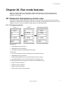
Chapter 20. Run mode features............................................................................. 71
20.1 Sequence transparency across cues. .................................................................................... 71
20.1.1 Transparency (Xciter).................................................................................................... 71
20.1.2 NO transparency ........................................................................................................... 72
20.1.3 Precautions ................................................................................................................... 72
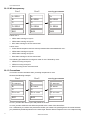
20.2 Basic cue dialog ..................................................................................................................... 73
20.2.1 Activate – deactivate sequences................................................................................... 73
20.2.2 Sequence trigger and step mode .................................................................................. 73
20.2.2.1 Internal trigger ......................................................................................................... 74
20.2.2.2 Manual trigger ......................................................................................................... 74
20.2.2.3 BPM trigger ............................................................................................................. 74
20.2.2.4 Audio trigger ............................................................................................................ 75
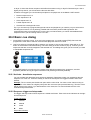
20.3 Extended cue dialog............................................................................................................... 75
20.3.1 Add/replace background scene..................................................................................... 76
20.3.2 Add/replace sequence .................................................................................................. 76
20.3.3 Remove elements from cue .......................................................................................... 76
20.3.4 Assign playback scenes to banks and faders ............................................................... 77
20.3.5 Link a playback bank to a cue....................................................................................... 77
20.3.5.1 Audio settings.......................................................................................................... 77
20.4 Store run mode settings ......................................................................................................... 78
20.5 Playback controls ................................................................................................................... 78
20.5.1 Activate and bounce override playbacks....................................................................... 79
20.5.2 Deactivate override playbacks ...................................................................................... 79
20.5.3 Auto lock........................................................................................................................ 79
20.6 Cue lists.................................................................................................................................. 79
20.6.1 Run cue list.................................................................................................................... 79
20.6.2 Clear cue list.................................................................................................................. 80
20.6.3 Edit cue list .................................................................................................................... 80
Chapter 21. Direct access features ....................................................................... 83
21.1 Pitch control and freeze.......................................................................................................... 83
21.2 Master, Master Flash and Black Out ...................................................................................... 83
21.3 DA buttons: SMK, STRB, EXT1 and EXT2 ............................................................................ 83
Chapter 22. PC software......................................................................................... 85
22.1 Software installation ............................................................................................................... 85
22.2 Firmware manager ................................................................................................................. 85
22.2.1 Update IO controller ...................................................................................................... 85
22.2.2 Update main controller .................................................................................................. 86
22.3 Library manager ..................................................................................................................... 86
22.3.1 Add a fixture definition................................................................................................... 86
22.3.2 Remove a fixture definition............................................................................................ 86
22.3.3 Update Xciter library...................................................................................................... 86
22.3.4 Export to lib ................................................................................................................... 87
22.4 Backup / Restore .................................................................................................................... 87
22.4.1 Backup .......................................................................................................................... 87
22.4.2 Restore .......................................................................................................................... 87
22.4.3 Clear show..................................................................................................................... 88
22.4.4 Clear password.............................................................................................................. 88
Chapter 23. Specifications - Xciter ........................................................................ 89
Introduction
Chapter 1. Introduction
Thank you for selecting the Martin Xciter. The Xciter is a hands-on lighting control tool for DJs and lighting
operators. This lighting controller allows operators to instantly manipulate the light show via easy-to-use
buttons and faders for spontaneous lighting effects. Ideal for clubs, small touring applications, even larger
mobile DJs, Xciter puts programming, playback and live manipulation of light shows at your fingertips.
Instant pitch control, freeze, flash, blackout, master control and many other features are standard . Apply
any effect and delay to any parameter for more advanced effects. Functions like strobe, smoke and more
can be assigned to each of four programmable customizable buttons for personalized, intuitive control.
Assign effects, scenes or dimmer to any of six faders and flash buttons and access them live during
playback. Keep your finger on the pulse by increasing or decreasing the show speed by up to 5 times using
the convenient pitch fader.
With Xciter you can control up to 20 fixtures, each up to 48 channels - max of 512 channels (soon to
control up to 40 fixtures with a software upgrade). Up to 160 cues containing 4 sequences can run
simultaneously. Sequences can be triggered via an internal clock, manually or via audio or BPM. Up to 10
manual override scenes can be accessed during playback.
Also incorporated are 20 general-purpose buttons so operators can select cues or fixtures directly. Xciter
also includes a joystick for manual pan/tilt control. Pan/tilt effects include timing effects and 20 pan/tilt
presets. Other features include direct access to dimmer channels, a master fader adjustment for general
light intensity control, and easy control of generic dimmers.
Extremely easy to navigate, Xciter features an easy-to-read, blue backlight LCD display for show menu,
dialogue and fader label presentation, as well as a jog wheel that makes it easy to scroll through fader
pages. Connect your PC directly to Xciter via the USB connection to update fixture libraries, export/import
shows, for show back up, editing, and more.
The Xciter comes with the following:
•
User manual
•
5 meter (16 ft.) 3-pin XLR cable
•
XLR termination plug
•
3-wire 1.5 meter (5 ft.) IEC mains cable
1.1 Naming conventions used in this manual
The following conventions are used in this user manual:
[x]
Key with label ‘x’
{x}
Soft key with label ‘x’
GP
Group/page key
MATRIX
Number and letter keys
ARROW
The previous and next keys with the arrow left and right
DA
Direct Access keys (Smoke, Strobe, Ext1, Ext2)
MF
Master fader
SMF
Sub Master Fader
MB
Master bounce
SMB
Sub Master Bounce keys
LCD1
The main LCD
LCD2
The fader LCD
SCR1
Jog wheel next to LCD1
Introduction
SCR2
Jog wheel next to LCD2
CS
Cue Scene
PB
Playback
SEQ
Sequence
1.2 Safety
This product presents risks of lethal or severe injury due to electric shock. Read this manual before
powering or installing the console, follow the safety precautions listed below and observe all warnings in
this manual and printed on the console.
If you have questions about how to operate the console safely, please contact your Martin dealer or call the
Martin 24-hour service hot line at +45 70 200 201 or +1 954 858 1800.
Warnings
Always ground (earth) the console electrically.
Use only a source of AC power that complies with local building and electrical codes and has
both overload and ground-fault protection.
To reduce the risk of fire or electric shock, do not expose this appliance to rain or moisture.
Refer any service operation not described in this manual to a qualified technician.
Do not modify the console or install other than genuine Martin parts.
The Xciter is not for domestic use.
Use the device only as described.
Do not operate the device with the cover removed.
Immediately repair or replace damaged power cords.
There are no user-serviceable parts inside; refer all service to a qualified technician.
To reduce the risk of electric shock, do not remove the cover (or back).
RISK OF ELECTRIC SHOCK
DO NOT OPEN
The lightning flash with arrowhead symbol, within an equilateral triangle, is intended
to alert the user to the presence of un-insulated “dangerous voltage” within the
product’s enclosure that may be of sufficient magnitude to constitute a risk of electric
shock to persons.
The exclamation point within an equilateral triangle is intended to alert the user to the
presence of important operating and maintenance (servicing) instructions in the
literature accompanying the appliance.
1.2.1 Important safety instructions
1. Read these instructions.
Introduction
2. Keep these instructions.
3. Heed all warnings.
4. Follow all instructions.
5. Do not use this apparatus near water.
6. Clean only with dry cloth.
7. Do not block any ventilation openings, Install in accordance with the manufacturer’s instructions.
8. Do not install near any heat sources such as radiators, heat registers, stoves, or other apparatus
(including amplifiers) that produce heat.
9. Follow all safety instructions when installing and using a grounding-type plug.
10. Protect the power cord from being walked on or pinched particularly at plugs, convenience
receptacles, and the point where they exit from the apparatus.
11. Only use attachments/accessories specified by the manufacturer.
12. Unplug this apparatus during lightning storms or when unused for long periods of time.
13. Refer all servicing to qualified service personnel. Servicing is required when the apparatus has
been damaged in any way, such as power-supply cord or plug is damaged, liquid has been spilled
or objects have fallen into the apparatus, the apparatus has been exposed to rain or moisture,
does not operate normally, or has been dropped.
Installation
Chapter 2. Installation
2.1 Hardware
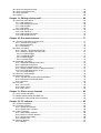
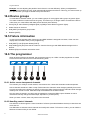
Most of the hardware connections are done on the back panel of the console.
MAINS
MIDI
DMX-512
Audio
expansion
2.1.1 Power connection
The Xciter does not need a mains adapter. It takes main supply directly into the IEC mains
connector. The power supply will automatically adapt to the mains voltage that is used in your area.
The power supply is quite insensitive to power drops. It can handle drops of up to 0.5 s.
The power supply is auto-ranging:
•
90VAC – 250 volts -AC
•
50Hz – 60Hz
The power rating is indicated on the serial number label that can be found on the base of the fixture.
2.1.1.1 Installing a plug on the mains lead
Warning!
For protection from dangerous electric shock, the fixture must be grounded (earthed).
The AC mains supply shall have overload and ground-fault protection.
The mains plug is the power disconnect device for the fixture. Note that when the
miains input plug is attached that the unit is connected to the mains power circuit. The
mains input plug shall remain accessable so that the mains circuit can be disconnected
from the fixture.
Important!
Verify that the feed cables are undamaged and rated for the current requirements of all
connected devices before use.
The fixture’s mains lead requires an approved grounding-type cord cap that fits your local power
distribution cable or outlet. This is not supplied. Consult a qualified electrician for proper installation.
Following the cord cap manufacturer’s instructions, connect the appropriate wires to ground (earth),
live, and neutral. The following table below shows some common wire identification schemes.
Function
Wire (EU)
Wire (US)
live
brown
black
neutral
blue
white
ground
yellow/green
green
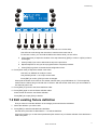
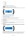
2.1.2 DMX connection
Xciter has one DMX-512 universe. On the back panel of the console you can see one 5-pin input,
one 3-pin output and one 5-pin output. The 3-pin and 5-pin outputs belong to the same DMX
universe but they are both buffered. This means they can be used together without violating the
DMX specifications.
Xciter user manual
11
Installation
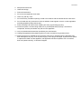
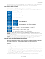
2.1.2.1 Devices
out
in
out
in
out
in
out
DMX terminator
3-pin or 5-pin out
in
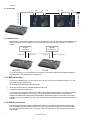
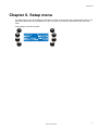
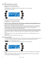
2.1.2.2 Master/slave
Because the 3-pin and 5-pin DMX out can be used together, you can link two consoles together and
attach your devices at the same time. If you want to link more slaves to the master, you need a
splitter.
devices
universe 1
3-pin out
devices
universe 2
5-pin out
5-pin in
MASTER
3-pin or 5-pin out
SLAVE
If you are planning to use a master/slave connection, you need to make the appropriate settings in
the setup menu. See master/slave configuration.
2.1.3 MIDI connection
If you have a MIDI device to control your shows, you can connect it to the MIDI-in socket. You can
also patch through via MIDI-thru.
Xciter accepts the following MIDI commands:
•
Note ON and note OFF to activate playbacks and cues.
•
Program change to activate cues.
If you press a cue or bounce button with a MIDI command assigned to them, Xciter also sends that
command through MIDI-out. This way you can also use MIDI for master/slave connections of
multiple consoles without the need for DMX splitters. Remember however that Xciter only accepts
the MIDI commands noted above, which are only useful for on/off actions of cue buttons and bounce
buttons.
2.1.4 AUDIO connection
The desk also has audio triggering capabilities. There is an internal microphone if no direct audio
feed is available. We recommend a direct audio line to get the best results out of the audio trigger.
You can plug audio into the 6.3mm mono jack. When using the line-in, the internal microphone is
switched off.
12
Xciter user manual
Installation
Use standard audio signals like the pre-amp output from your audio mixer to get the best results. If
you want to have even more control over the audio trigger, you can place an equalizer between the
audio source and the console.
Warning: DO NOT use an amplified output like the one coming from the speaker amplifier as it may
damage the console.
2.1.5 I²C expansion
Use this connector to attach accessories to the console.
As you can see, the I²C expansion port is the same as MIDI. Connecting MIDI to this port will not
damage the console.
Warning: Martin accessories only. DO NOT connect other devices, as this may damage the console.
2.1.6 USB link to PC
You need a USB-A to USB-B cable to connect your Xciter to a desktop or laptop. Use the USB link
to upload new firmware, download and upload fixture definitions and do backup/restore of shows.
Later in this manual, we will explain how to use the PC applications that come with Xciter.
2.1.7 Desk light or LittLite
The sole purpose of the USB-A connector on the front panel is to supply power for a desk light.
Attention: you can draw a maximum of 315 mA from this port. Check the specification of your desk
light before using it.
2.2 Software
Before Xciter can communicate with your PC or laptop, you need to install the USB drivers and
applications first. You can find them on the disk that comes with the Xciter. We recommend that you
get the latest applications from the Martin support site. They may contain newer firmware and new
fixture definitions.
1. Launch “install.exe” to install the drivers and PC applications.
2. Use the default directory or type in a new path.
3. Press “Install” to start the installation.
4. Some error messages may pop up if previous driver or application versions were found. Simply
ignore them by pressing “OK”.
Xciter user manual
13
Power on/off
Chapter 3. Power on/off
You can find the power button in the top left corner.
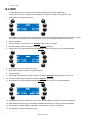
3.1 Power on
1. Make sure the Xciter has mains power.
2. Press [ON].
Xciter scans the internal file system and restores the database.
The intro screens appear on LCD1 and LCD2.
3.2 Power off
The Xciter’s power off is safeguarded by a 2 second delay. Meaning you have to hold the ON button for at
least 2 seconds.
1. Hold [ON] until the Displays and LED’s go dark.
2. Release the power button.
Xciter user manual
15
Joystick operation
Chapter 4. Joystick operation
If you are using the Xciter for the first time, you may need to calibrate the joystick. See joystick calibration
in the setup menu.
1. Press {Joystick} in the setup menu.
2. Move the joystick to all extremes (in a circle).
3. Press store to store the calibration.
4. Press any button to continue. Xciter returns to the setup menu.
4.1 Operation in the programmer
Xciter’s self-centering joystick always works in relative mode.
When you push the joystick in a certain direction, the beam will move in that direction and the further you
push the joystick from the centre, the faster the beam will move.
Sometimes the individual fixtures of a group are positioned differently so the beams all move in different
directions when you manipulate the joystick. You can solve this in the patch with PAN-inverse, TILTinverse and PT-swap.
Press [PAN] and [TILT] to activate / deactivate the joystick in the programmer. You can also use these
buttons to lock the pan or tilt action of the joystick.
Use [C/F] to toggle between coarse and fine movement.
The joystick also has a built-in button. Press the joystick down to bring the fixtures back to their home
position (library defaults for PAN and TILT).
4.2 Operation in cue (run mode)
The [C/F] button becomes the BPM record button in cue (run mode). Pressing this button in a certain pace
will cause the sequences in BPM mode to follow this pace.
The [TILT] button becomes the step button in cue (run mode). Pressing this button will cause sequences in
manual mode to advance one step.
Xciter user manual
17
Desk light operation
Chapter 5. Desk light operation
If you have a desk light installed. You can adjust the intensity by holding down [SHIFT] while you turn
SCR1.
Xciter user manual
19
Setup menu
Chapter 6. Setup menu
The setup menu is only accessible from the start-up screen. If the Xciter is not in programmer mode, it will
ask for the password to go to programmer mode. You have to provide this password to enter the setup
menu.
Press {Setup} in the intro screens
Xciter user manual
21
Fixture library
Chapter 7. Fixture library
The Xciter is delivered with most Martin fixtures already in its library. On top of that, one of the PC
applications called ‘library manager’ holds a couple of hundred more fixtures from other brands. Later in
this manual you will learn how to put them from the PC library in the Xciter library. The console needs a
fixture library to access the internal control channels (dimmer, shutter, color wheels, gobo wheels, effect
wheels, pan, tilt…) of fixtures. You can also add, remove and edit fixture definitions. If you can find your
fixtures in this library, there is no need for you to create your own profiles. You can proceed straight to the
patch. You can still come back to the library editor to modify the fixture profiles to your own needs.
Example: To put a default value on the focus.
1. Press {Library} in the setup menu.
2. Select a fixture category (Example: moving mirror).
3. Select a manufacturer (Example: Martin).
7.1 Create a new fixture definition
First you have to select the category and manufacturer subfolders where you want to create your definition.
1. Press [LOAD] to add a fixture definition.
2. Xciter calls the fixture definition editor.
3. Press {Fixture type name} to name the fixture definition.
Use ARROW or SCR1 to move the cursor.
Use NL 1-10 to input numbers and NL 11-19 to input letters (Example: test).
Press [ENT] to confirm, [ESC] to cancel.
4. Press {Channel cnt:} to adjust the number of internal control channels.
Use ARROW or SCR1 to modify the value (Example: 8).
Use [CLEAR] and NL 1-10 to input a new value.
Press [ENT] to confirm, [ESC] to cancel.
5. Press {Channel Config} to configure the internal control channels.
Xciter user manual
23
Fixture library
a. Use ARROW or SCR1 to select a control channel.
b. Press [EDIT] to set the parameters of the selected channel.
c.
Use SM 1-6 to modify the parameters of the selected channel.
To fine-tune a value, you can hold the SM bounce button while you turn SCR2.
d. Use SM bounce button 1 to toggle between coarse and fine (MSB and LSB).
Upper case indicates a coarse channel; lower case indicates a fine channel.
e. [STORE] to store the parameters of the selected channel.
6. Repeat the previous steps (a – e) until you have configured all control channels.
Xciter checks whether you have configured all control channels before exiting the fixture definition editor. If
not Xciter asks you to retry.
7. Press [ESC] to return to the fixture definition editor.
8. Press {Advanced Config} to go to the advanced configuration menu.
9. The Lamp on, Lamp off and Reset procedures are programmed in the same way. We will use Lamp on as
an example.
10. Press the softkey next to the procedure you wish to make.
11. Press [LOAD] to create a procedure in case there is none.
Xciter adds the first step automatically.
If you are editing a fixture definition you can also press [EDIT] if you want to modify an existing procedure or press
[CLEAR] to delete it. Xciter asks for confirmation. Press [ENT] to confirm, [ESC] to cancel.
24
Xciter user manual
Fixture library
a. Use SM 1-6 to adjust the internal control channels in the current step.
Use SCR2 to scroll through the channels in case there are more than 6.
To fine-tune a value, you can hold the SM bounce button while you turn SCR2.
b. Press {Step time} to adjust the duration of the step followed by [ENT] to confirm or [ESC] to leave
unchanged.
c.
Press [LOAD] if you want to add another step to the procedure.
d. Repeat steps 9a-9c until you have programmed the complete procedure.
e. Press [ESC] to go back to the advanced configuration menu.
12. Press {Shut close} to adjust the shutter close value.
Use SCR1 or ARROW to modify the value.
Use [CLEAR] and NL 1-10 to input a new value.
Press [ENT] to confirm, [ESC] to leave unchanged.
Xciter puts the shutter close value on the shutter channel when you pull MI below 3%. This is especially
useful when the fixture has got a shutter but no dimmer. With the shutter close value you can still black it
out when MI goes to 0%.
13. Press [ESC] to go back to the fixture definition editor.
14. Press [ESC] again to exit the fixture definition editor.
Xciter will ask to store the new fixture definition.
Press [ENT] to accept, [ESC] to decline.
7.2 Edit existing fixture definition
First you have to locate the definition in the category and manufacturer subfolders.
1. Select the definition you wish to edit.
2. Press [EDIT] to edit the selected fixture definition.
Use the same procedure as described in 7.1 to edit the definition.
Xciter will not allow you to edit critical parameters (like channel cnt) of a fixture definition if this definition is
used in the patch.
Xciter user manual
25
Fixture library
7.3 Remove fixture definition
First you have to locate the definition in the category and manufacturer subfolders.
1. Select the definition you wish to remove.
2. Press [CLEAR] to remove the selected fixture definition. Xciter will ask for a confirmation.
3. Press [ENT] to confirm, [ESC] to cancel.
Xciter will not allow you to delete a fixture definition if this definition is used in the patch.
26
Xciter user manual
Patch
Chapter 8. Patch
Before you start programming, Xciter needs to know which devices are connected to its DMX universe and
how it will control them. This is where the patch comes in. To patch a device means to connect it to the
Xciter controls, so you are able to manipulate it.
The Xciter controls are divided into three groups, which enable you to control:
•
Up to 40 fixtures.
•
Up to 20 dimmers.
•
Up to 4 direct access devices.
Press {Patch} in the setup menu to access the patch menu.
8.1 About physical channels and control channels
You will encounter the terms ‘physical channel’ and ‘control channel’ a lot in this manual. You need to know
what they mean to better understand this manual.
Physical channels or DMX channels are the channels as they occur on the DMX output. They start at
channel 1 and end at channel 512. Channel 0 is reserved for special purposes which we will not discuss in
this manual.
Example: Dimmer 1 is on channel 480.
In this manual we are mostly talking about selected devices and the control channels we use to manipulate
them. We rarely talk about the actual channel on the DMX output.
Example: Use SM1 to set the value of dimmer 1 to 128.
In the above examples the control channel “Dimmer 1” is patched to physical channel 480.
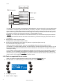
8.2 Fixtures
Each fixture type has its own set of control channels, which are described in a fixture definition.
Xciter user manual
27
Patch
internal library
DMX channels
Martin MX-4
22
23
24
25
26
27
28
SHUT
COLW1
GOBW1
PAN
TILT
PTSPD
CGSPD
fixture type
control
channels
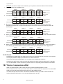
The internal control channels have subsequent DMX addresses, thus the fixture will occupy a certain space
on the DMX chain beginning at the start address you specify in the patch. Occupied space relates directly
to the number of internal control channels, meaning the more control channels your fixture has, the more
space it will occupy on the DMX universe. A Fixture type can have up to 48 control channels. But you have
to consider a maximum of 512 physical channels (1 complete DMX universe).
Example: You cannot patch 40 devices of 48 channels because you would need 1920 physical channels.
Thanks to the interactive features and intuitive user interface, you will find it easy to patch fixtures without
overlapping.
1. Press {Fixture Patch} in the patch menu.
The Xciter asks you to select a fixture number.
2. Use [FIX] to toggle between fixture page one (fixtures 1-20) and two (fixtures 21-40).
You can see the current page on LCD2.
When you select a fixture number, there are two possibilities. Either the fixture number is empty
(unpatched) or occupied (already patched). An illuminated N/L indicates a patched fixture number. You can
edit the patch data at any time. Beware that certain modifications in this data may corrupt the show that is
currently in memory.
If you unpatch a fixture number, the DMX device attached to this number will no longer appear in the show.
However, you can re-address fixtures without corrupting the show, provided that you also re-address the
devices on your rig accordingly. Example: If you patch a fixture two channels further in the Xciter you also
need to put the fixture address in the rig two channels further.
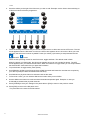
8.2.1 Patch an unpatched fixture number
When you select an unpatched fixture number, Xciter reports this. Example: N/L 10.
1. The LED under NL 10 starts blinking to indicate that fixture number 10 is selected.
2. Press [ENT] to patch.
3. Select a fixture category.
28
Xciter user manual
Patch
Example: Moving Mirror.
4. Select a fixture manufacturer.
Example: Martin.
5. Select a fixture type from the list.
Example: MX-10.
6. Press [ENT] to confirm.
If you cannot find the necessary fixture type, you have to use the library editor to create one on the fly, or
use the PC application to download one via USB.
Xciter automatically detects the first available space on the DMX chain and suggests the start address
(Example: 1)
7. If you wish to assign another start address, press {ADDR:}.
Use ARROW or SCR1 to adjust the value.
[CLEAR] and NL 1-10 to input a new number.
[ENT] to confirm, [ESC] to cancel.
8. When you specify a start address, Xciter will check if there is enough space behind that address to place
the fixture. If not, the console reports this and suggests the start address of the next available space. Press
[ENT] to accept the suggested number, [ESC] to decline.
Depending on the orientation of the patched fixture on the rig, you can inverse the pan, inverse the tilt and
swap pan and tilt. This is a global setting for the fixture to make pan/tilt control with the joystick easier. As
you will see later in this manual, you can still invert channels for your show in the programmer.
9. Press the softkeys next to the options to toggle them on/off.
TILT inverse
PAN inverse
PAN/TILT swap
You can choose to exclude a device from master and/or blackout. Exclude from master means the dimmer
or shutter of the fixture is not affected by the master fader. Exclude from blackout means the blackout
button does not affect the dimmer or shutter of the fixture. Press the softkey next to the options to toggle
them on/off.
You can see the status of every option by looking at the square next to it. A filled square means on, an
empty one off.
10. Repeat these steps until you have patched all fixtures on your rig.
Xciter user manual
29
Patch
8.2.2 Edit a patched fixture number
1. Select a fixture that is already patched.
Example: NL10 to select fixture number 10.
The LED under NL 10 starts blinking to indicate that fixture number 10 is selected.
Xciter shows the patch data.
2. If you wish to assign another start address, press {ADDR:}.
Use ARROW or SCR1 to adjust the number.
[CLEAR] and NL 1-10 to input a new number.
3. When you specify a start address, Xciter will check if there is enough space behind that address to place
the fixture. If not, the console reports this and suggests the start address of the next available space. Press
[ENT] to accept the suggested number, [ESC] to decline.
4. Depending on the orientation of the patched fixture on the rig, you can inverse the pan, inverse the tilt or
swap pan and tilt. This is a global setting for the fixture to make pan/tilt control with the joystick easier. As
you will see later in this manual, you can still invert channels for your show in the programmer.
Press the softkeys next to the options to toggle them on/off.
5. You can choose to exclude a device from master and/or blackout. Exclude from master means the dimmer
or shutter of the fixture is not affected by the master fader. Exclude from blackout means the blackout button
does not affect the dimmer or shutter of the fixture. Press the softkey next to the options to toggle them
on/off.
6. You can see the status of every option by looking at the square next to it. A filled square means on, an
empty one off.
7. Repeat these steps on other fixtures you want to edit.
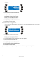
8.2.3 Clear patch data
If you want to assign a different fixture type to a fixture number, you have to clear that fixture number first. If
you remove a fixture from the patch permanently, that fixture will no longer take part in the show.
Example: NL 10 to select fixture number 10.
1. The LED under NL 10 starts blinking to indicate that fixture number 10 is selected.
2. Press [CLEAR] to delete the patch data. Xciter will ask for confirmation. Press [ENT] to confirm, [ESC] to
cancel.
After a successful delete operation, Xciter reports an unpatched fixture number. If you want to delete
another fixture, you have to repeat steps 1-2.
30
Xciter user manual
Patch
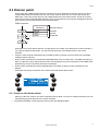
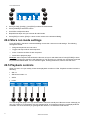
8.3 Dimmer patch
Fixture types are predefined because they have their own set of subsequent channels, which you cannot
change. Most dimmers however have only one control channel, which you can move freely across the
DMX chain. That is why Xciter does not use predefined devices in the dimmer patch. Above all you have
more direct access to physical DMX channels. The more experienced user may take advantage of this low
level access to control other devices with the dimmer patch.
DMX channels
Dimmer 1
160
175
176
BLUE
RED
GRN
dimmer device
internal
control
channels
180
Xciter permits up to 20 dimmer devices. A single device can contain up to 255 dimmer control channels. If
you compare fixtures and dimmers, you will conclude that most of the differences lie in the control
channels:
•
A fixture control channel manipulates only one DMX channel. A dimmer control channel can manipulate
multiple physical channels.
•
Fixture control channels have subsequent DMX addresses when you patch them. The DMX Channels you
patch to a dimmer control channel do not have to be subsequent; they can be anywhere on the DMX chain,
provided they are not occupied by the fixture or DA patch.
•
Fixture control channels have factory-defined labels. The labels of dimmer control channels are userdefined.
Press {Dimmer Patch} in the patch menu. Xciter shows the dimmer patch menu.
8.3.1 Create or edit dimmer labels.
When you start from scratch, the control channels have no labels. You have to create some before you can
start patching physical channels to the control channels.
1. Press {Dimmer labels}. Xciter shows the first 6 of 255 user definable labels.
Xciter user manual
31
Patch
2. Use SCR2 to scroll through the control channels.
3. Select a label with the SM bounce button below it.
4. Use ARROW or SCR1 to move the cursor.
Use NL 1-10 to input numbers and NL 11-20 to input letters (maximum 5 characters).
Press [ENT] to confirm, [ESC] to cancel and return to the previous label.
5. Repeat steps 2-4 until you have created or edited all labels you need.
If you only need 10 labels, you do not need to give labels to all 255 control channels; the patch will work
with 1 or more.
6. Press [ESC] to exit the label editor and return to the dimmer patch menu.
Xciter asks if you wish to store the new labels. Press [ENT] to confirm, [ESC] to decline. Xciter returns to the
dimmer patch menu.
8.3.2 Create or edit dimmer devices
To create a dimmer device, you need to select the control channels and patch some physical channels to
them.
1. Press {Dimmer patching}.
2. Xciter displays all control channels that have been given a label.
3. Select one of 20 dimmer devices with NL 1-20.
4. Uses the SM bounce buttons below the control channels to select one of them (Example: dim1).
5. Press [EDIT] to assign and configure physical channel(s) behind the selected control channel.
32
Xciter user manual
Patch
6. Use SCR2 or ARROW to scroll through the physical channels (1-512).
7. Press the SM bounce button below the physical channel you wish to attach to the control channel.
8. Press the SM bounce button again to invert the channel. Note that the brackets around the channel value
tell you whether it is inverted or not.
9. To remove a physical channel, hold [CLEAR] and press the SM bounce button below the physical channel.
10. Press the bottom right softkey to switch between the following settings for the physical channel(s):
a.
High limits
b.
Low limits
c.
Default values
11. Use the faders to adjust these settings. In some cases you may find faders to difficult to adjust values. You
can hold down the bounce button under the fader while you turn SCR2 to adjust the value.
12. Press [STORE] to save your settings. Xciter returns to the previous menu.
13. Repeat these previous steps until you have configured all control channels you need under the selected
dimmer number and until you have patched all dimmer numbers you need.
14. Press [ESC] to exit the dimmer patch. Xciter will ask whether you want to save the new dimmer setup.
Press [ENT] to confirm, [ESC] to decline.
If you have not assigned any physical channels to the dimmer unit yet, {Next used} will bring up the first
available channel on the DMX chain. In case you have already assigned physical channels, you can easily
look them up with the {Next used} function.
By default you will see occupied channels as unit numbers (Example: Fx-01 for fixture 1). Press
{Units}/{Labels}to toggle unit display and label display. Looking at the unit labels in respect to their physical
channel is very useful (Example: for debugging fixture profiles or patch).
Generic lights like PAR-cans work great with the audio features of the effect generator. If you want to
create delays in the audio effects, you need to place each dimmer or bar under a different dimmer button,
but under the same dimmer label to make control easier.
8.4 DA patch
DA stands for Direct Access. You have 4 DA buttons on the console. The DA patch lets you program two
static scenes behind each DA button. Xciter will not allow you to use channels that are occupied by other
devices. The main purpose of the DA button is to momentarily control devices like smoke machines and
strobes.
DA scenes cannot be used in the programmer. If you wish to use a strobe in the show, you need to patch it
as a fixture or dimmer device but you can no longer use it under a DA button because of the restriction
mentioned above. But you can still make it direct access by putting it in a playback.
Beware that if you adjust the DMX address of your DA devices, you also need to adapt the DA scenes that
use those devices.
1. Press {DA Patch} in the patch menu. Xciter shows the DA patch menu.
Xciter user manual
33
Patch
2. Press the softkey to the right of the DA scene you wish to edit. Example: smoke. Xciter shows a dialog on
LCD2 that looks a lot like the programmer.
3. There are actually two scenes that you can set for each button: an ON scene and an OFF scene. The ON
scene appears when the DA button is active; the OFF scene appears when it is inactive. When you enter
the patch, the ON scene is shown by default. Press {On values} / {Off values} to swap between the ON
and OFF
scene.
There are two operating modes for each DA button: toggle and flash. The default mode is flash.
When the button is in flash mode, the ON scene appears as long as you hold the DA button. The OFF
scene appears when you release the DA button. When the button is in toggle mode you can swap between
the ON and OFF scene each time you press the DA button
4. To put the button in toggle mode, press {Flash}.
5. Use ARROW or SCR2 to scroll through the 512 DMX channels and locate the ones that are occupied by
your device (Example: DMX controlled smoke machine).
6. Use SM below a physical channel to activate it and set the value.
7. To fine-tune a value, you can hold the SM bounce button while you turn SCR2.
8. Use the SM bounce buttons to make unwanted channels transparent again. Example: In case you
accidentally activated other physical channels.
9. Press [STORE] to store your settings in the patch table or [ESC] to return to the previous values.
10. Press [ESC] to return to the DA patch menu.
The procedure is the same for all DA buttons.
34
Xciter user manual
Auto start
Chapter 9. Auto start
When start is enabled, Xciter will run a certain cue list after startup. As you will see in the cue list editor,
you can also execute lamp procedures in the cue list.
Example: If the operator is late, other persons, who do not know the console, can still do a lamp on and
start up a small show with the auto start function. Of course you need to select a cue list with lamp
procedures to do this.
1. Press {Auto Start} in the setup menu to call the auto start dialog.
2. Use PG and NL 1-20 to select cue. The page and number of the selected cue appear on the bottom line.
3. Press [ENT] to confirm or [ESC] to cancel.
If you have confirmed, Xciter shows the message ‘Auto start settings stored! Press any key!
Press any button to continue.
4. If you wish to disable the auto start feature, press [CLEAR].
5. Xciter asks for confirmation.
6. Press [ENT] to confirm or [ESC] to cancel.
7. Press [ESC] to exit the auto start dialog.
Xciter user manual
35
Access level
Chapter 10. Access level
The access level determines how accessible the console is to the user. There are three access levels:
1. Programmer level
2. Operator level
3. Dummy level
10.1 Different modes for different people
10.1.1 Programmer mode
You have access to all functions.
10.1.2 Operator (run) mode
You have access to all playback functions.
The following functions are disabled:
•
[EDIT]. You cannot edit existing show elements.
•
[STORE]. You cannot store new show elements or settings.
Example: Even if you are a programmer, you can safely operate the console in this mode.
Example: Your resident DJ knows the controller well and you want him to get the best out of it.
10.1.3 Dummy mode
You have limited access to playback functions and cannot edit or store.
The following functions are disabled:
•
[EDIT]. You cannot edit anything.
•
[STORE]. You cannot store anything.
•
[↕] limited. You can only modify the audio triggers from cue.
•
[CLEAR]. You cannot clear anything.
•
[LOAD] limited. You can only load a cue list.
•
[FIX] & [DIM]. You cannot access fixtures and dimmers.
Example: At an exhibition you want to increase interactivity with certain art objects. So you can have
visitors (who do not know anything about light) safely operating the console and change the lighting
themselves.
Example: You have a visiting DJ who does not know anything about the console. Have him run a cue list
with go and give him some playbacks.
10.2 Changing user modes
10.2.1 From programmer to other
In programmer mode, Xciter allows you to access the setup menu immediately.
1. Press {Access level} in the setup menu.
Xciter user manual
37
Access level
2. Press {Operator} to switch to operator mode.
3. Press {Dummy} to switch to dummy mode.
4. Press {Password} to change the password.
Use ARROW or SCR1 to move the cursor.
Use NL 1-20 to input letters and numbers.
Press [ENT] to confirm, [ESC] to cancel.
5. Press [STORE] to store the new access level.
6. Press [ESC] to leave the dialog.
10.2.2 From other to programmer
In a user mode other than programmer Xciter will ask for the programmer password when you try to enter
the setup menu.
7. Use ARROW or SCR1 to move the cursor.
Use NL 1-20 to input numbers and letters.
Press [ENT] to confirm, [ESC] to cancel.
8. If you have entered the correct password, the setup menu appears.
9. Press {Access level} in the setup menu.
10. Press {Operator} to switch to operator mode.
11. Press {Dummy} to switch to dummy mode.
12. Press [STORE] to store the new access level.
13. Press [ESC] to leave the dialog.
If you have forgotten or lost the password, you can erase it with the backup/restore PC application.
38
Xciter user manual
File manager
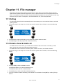
Chapter 11. File manager
Xciter has its own file system stored on FLASH memory which does not need battery backup. The file
system makes it easier to transfer single files to a PC or laptop. We also remove corrupt files when Xciter
boots. A corrupt file is mostly the result of a power failure during storage. But most important, you can only
loose one file (one scene, one sequence, one fixture definition, etc.) when the power fails.
11.1 Defrag
The file system does all of this automatically but we recommend you do an occasional clean-up of the file
system yourself.
1. Press {File mngr} in the setup menu. Xciter scans the file system. When finished, it shows the following
dialog.
2. Press {Delold} to make old files dirty, which means they will be marked to erase.
3. Press {Defrag} to clear dirty space and create free memory.
11.2 Delete show & delete all
The delete show function allows you to delete all show data to start from scratch. The library content,
patch, groups and some general files with settings are kept.
The delete all functions clears the entire file system, all data. Of course, the firmware remains.
1. Press {File mngr} in the setup menu. Xciter scans the file system. When finished, it shows the following
dialog.
2. Press [CLEAR] to show the delete functions.
Press {Delete Show} if you wish to delete the show.
Press {Delete All} if you wish to delete all data.
3. Press [ESC] if you wish to exit without deleting anything.
4. If you have chosen to delete something, Xciter will ask for confirmation. Press [ENT] to confirm, [ESC] to
decline.
Xciter user manual
39
Advanced setup
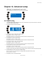
Chapter 12. Advanced setup
Warning: for experienced users only!
Press {Advanced} in the setup menu to go to the advanced setup.
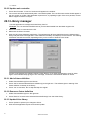
12.1 DMX Config
The standard DMX refresh rate of the Xciter is 33 Hz. Some fixtures may not work at this rate. In that case,
you need to adjust the DMX timings.
1. Press {DMX Config} in the advanced setup.
2. Press {MBB} to adjust the Mark Before Break length.
Use ARROW or SCR1 to modify the value.
Press [ENT] to keep the new value, [ESC] to decline and return to the previous value.
3. Press {BREAK} to adjust the Break length.
Use ARROW or SCR1 to modify the value.
Press [ENT] to keep the new value, [ESC] to decline and return to the previous value.
4. Press {MAB} to adjust the Mark After Break length.
Use ARROW or SCR1 to modify the value.
Press [ENT] to keep the new value, [ESC] to decline and return to the previous value.
5. Press {CHSPACE} to adjust the space between channels.
Use ARROW or SCR1 to modify the value.
Press [ENT] to keep the new value, [ESC] to decline and return to the previous value.
In case you want to restore the values to factory default, press the SM bounce button below the label ‘Deflt’.
6. Press [STORE] if you wish to store the new DMX settings.
Xciter will confirm the new values with the message ‘DMX config stored!! Press any key!
Press any button to continue.
7. Press [ESC] to return to the advanced setup.
Xciter user manual
41
Advanced setup
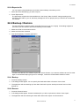
12.2 MIDI
These settings are only useful if you are linking a MIDI device to Xciter’s MIDI input.
MIDI notes can launch cues and bounce playbacks. Program changes can only launch cues.
1. Press {MIDI} in the advanced setup.
On the left you have the Xciter show elements and on the right the MIDI commands to launch them. If there
is no MIDI command linked to the show element, ‘NO cmd’ will appear behind the show element.
2. Press {Cue 0/00}.
3. Use PG and NL 1-20 to select a cue. Example: select cue 15 on page 2.
4. Press the softkey next to the MIDI command. Example: {NO cmd}.
5. Xciter asks you to send a MIDI command. Example: change to program 8 on your MIDI keyboard.
6. Press [ENT] to confirm or [ESC] to cancel.
7. Xciter links the MIDI command to the selected cue.
8. Press {PB 0/00}.
9. Use SCR2 and SM bounce buttons to select a playback. Example: select playback 4 in bank 10.
10. Press the softkey next to the MIDI command. Example: {NO cmd}.
11. Xciter asks you to send a MIDI command. Example: press note 20 on your MIDI keyboard.
12. Press [ENT] to confirm or [ESC] to cancel. Xciter links the MIDI command to the selected playback.
13. Repeat these steps until you have assigned all MIDI commands you need to Cues and playbacks.
14. Press [ESC] to leave the MIDI configuration. Xciter asks to store the new settings.
15. Press [ENT] to confirm or [ESC] to decline.
42
Xciter user manual
Joystick calibration
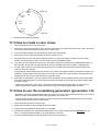
Chapter 13. Joystick calibration
If you are using the joystick a lot, the values it sends out may show a little drift, because of wear on the
components. The joystick calibration tool will solve this problem for you.
1. Press {Joystick} in the setup menu to access the calibration tool.
2. Move the joystick to all extremes in a circular motion a couple of times.
3. Press [STORE] to store the calibration data. Xciter confirms with ‘Limits saved! Press any key!
4. Press any button to continue. Xciter returns to the setup menu.
Xciter user manual
43
Test
Chapter 14. Test
The test menu contains some testing tools, which are meant for debugging purposes. They will not be
detailed in this manual.
Xciter user manual
45
The Xciter philosophy
Chapter 15. The Xciter philosophy
15.1 Building blocks
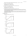
15.1.1 Scene
scene
scene time
active channels
fade time
The scene represents a single look, created with some or all of the patched fixtures. Xciter has two kinds of
scenes: background scenes and playback scenes. The background scene is added to a cue, whilst the
playback scene is assigned to a fader. They are essentially the same but separated in the Xciter so you
know all the time which scenes are used in cues and which ones are used in playbacks. This is especially
useful when you edit or delete scenes. A background scene can be easily stored as a playback scene and
the other way around.
The scene has two timing parameters attached to it: Scene Time (ST) and Fade Time (FT). These
parameters determine the transition of the current scene from the previous one.
Xciter can hold as many scenes as the memory allows, depending on the scene content (number of active
channels).
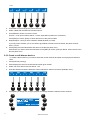
15.1.2 Sequence
Sequence
global scene time global fade time
step 1
scene time
fade time
step 2
scene time
fade time
step 3
scene time
fade time
step 4
scene time
fade time
Where the scene represents one look, the sequence has multiple looks or steps (up to 99), which are
shown one after another. Each step has got timing parameters that determine the transition from one step
into the next: Scene Time (ST) and Fade Time (FT). The scene time is the duration of the step. Adjusting
the scene time will make the sequence faster or slower. The fade time Determines how long the step takes
to reach its end values or the programmed look. As you will see later in this manual, you can adjust the
timing parameters globally, meaning each step gets the same parameters, or locally, meaning you can set
a different timing for each step.
Xciter can hold as many sequences as the memory allows, depending on the sequence content (number of
steps and number of active channels per step).
Xciter user manual
47
The Xciter philosophy
15.2 Show elements
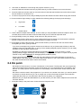
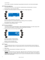
15.2.1 Cue
Cue
highest priority
Sequence A
trigger
run mode
Sequence B
trigger
run mode
Sequence C
trigger
run mode
Sequence D
trigger
run mode
Background scene
lowest priority
With 8 page buttons and 20 number buttons, you can launch 160 cues directly from the front panel. The
cue serves as a container to combine several building blocks in order to run them simultaneously (in
parallel). Xciter allows you to combine and launch four sequences and one background scene.
Xciter adds a wide variety of playback features to the cue:
•
Activate/deactivate background scene.
•
Activate/deactivate sequences.
•
Sequence trigger: internal, manual, audio and BPM.
•
Sequence run mode: forward, backward, bounce, random.
•
Comprehensive audio settings.
•
Quick link to playback bank.
•
Assign background scenes, playback scenes and sequences live
We will detail these features further in this manual.
15.2.2 Playback
Visible bank
Xciter has got 160 virtual banks of 6 playback faders. Of course only one bank (6 faders) is visible at a
time. Use playback faders to cross fade up to 6 playback scenes with a cue. We will explain how to use
playbacks further in this manual.
48
Xciter user manual
The Xciter philosophy
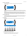
15.2.3 Cue list
Cue List
Cue
Step 1
Step options
Cue
Step 2
Step options
Cue
Step 99
Step options
With 8 page buttons and 20 number buttons, you can run 160 cue lists directly from the front panel. Each
cue list can contain up to 99 steps. At any given time, there can be only one running cue list.
The purpose of a cue list is to automatically playback cues as if you would launch them manually from the
front panel. Each step in the cue list refers to an existing cue.
To make the cue list more dynamic, you can attach extra options to each step:
•
GO: Xciter waits until you press the right arrow button before launching the next cue
•
WAIT with WT x S: Xciter waits x seconds until going to the next cue, overwriting the scene time of the
cue. The wait time can be maximum 6553.5 seconds.
•
FOLLOW with FT x S: Xciter adds x seconds to the scene time of the current cue before launching the
next cue.
•
GOTO with To=x: Xciter jumps to step x of the cue list. If you place this function at the end of a cue list
with To=1, that list will loop infinitely.
•
LOOP with Loopcount=x and To=y: Xciter jumps to step y of the cue list x times before proceeding to
the underlying steps.
•
LAMP_ON: Execute lamp on procedures for all patched fixtures.
•
LAMP_RESET: Execute reset procedures for all patched fixtures.
•
LAMP_OFF: Execute lamp off procedures for all patched fixtures.
Further in this manual, we will explain how to use cue lists in detail.
15.3 Programming aids
15.3.1 Effect generator
You have 255 effect generators at your disposal. The effect generator is not limited to pan and tilt; it can
affect every activated control channel in a scene. Use Xciter’s flexible effect generator to add dynamics to
you background scenes and playback scenes. So you can save up those valuable sequences for more
direct access in the cue. Xciter’s powerful engine also fades (between cues) and cross fades (between
cues and playbacks) on the swing, speed and delays of an effect.
Some key features of the effect generator:
•
Variable speed and swing.
•
Variable delay across channels.
•
Variable delay across fixtures.
•
Multiple shapes like sine, square, triangle, saw tooth, etc.
•
Bounce, reverse, reverse + bounce
•
Generator modulation
•
Audio modulation
•
BPM adaptive generators
Xciter user manual
49
The Xciter philosophy
The effect generator and its parameters will be discussed further in this manual.
15.3.2 Preset
Presets are very useful when you change the rig (fixture setup) a lot. Presets are preprogrammed values
that you can recall in your scenes. When you modify something in your rig (Example: move a fixture) you
don’t have to modify or reprogram all your scenes and sequences. You only need to modify the preset. All
scenes, where you have used the preset, will be instantly modified. Although presets require some
experience, they are worth checking out because they can save you a lot trouble when you modify the rig.
Xciter can store up to 160 presets, depending on the preset content.
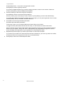
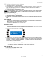
15.4 Process priority
We call a running scene or sequence a process. You may not see it but while you are doing a show or
programming, Xciter is running several processes in parallel (background scenes, sequences, playback
scenes, programmer, direct access buttons, lamp procedures, etc.). This means that several scenes are
trying to influence the DMX output at the same time. But these processes have different priorities.
highest priority
8
system functions
7
direct access
6
programmer, active
5
programmer, inactive
4
override playbacks
2
sequences
1
background scene
0
default
Lamp on, Lamp off, Lamp reset
smoke, strobe, extra1, extra2
active channels in scene editor, stored
temporary active channels in editor, not stored
scenes, activated by sub-master faders, during show
sequences A, B, C, D in the cue
background scene in the cue
default scene, when no other processes are active
lowest priority
Example 1: You have programmed some values on PAN and TILT of fixture number 10 in a background
scene. While this background scene is active in the show, you select fixture number 10 and move the
joystick. Now you put PAN and TILT values in the programmer on layers 5 and 6. These layers have a
higher priority, thus you override the PAN and TILT values of the cue scene.
Example 2: You have programmed a color value in the background scene. During the show you can
override this color with a playback scene because it will be running at a higher priority.
50
Xciter user manual
Program features
Chapter 16. Program features
Before you go ahead and start programming, you have to make sure that the fixtures on your rig are
patched to the Xciter controls.
There are basically two ways to program. You program from default, meaning you program without any
cues running. Or you program during show, meaning you program with cues running in the background,
overriding fixtures.
16.1 Select/deselect device
Xciter permits you to use moving lights and dimmers together in scenes, so you can switch between fixture
and dimmer pages freely without loosing device selections or channel settings.
1. Press [FIX] to select fixtures (intelligent lights).
Press [DIM] to select dimmers (generic lights).
2. Use [FIX] to swap between fixture pages. If [FIX] is lit, you are in page two (fixtures 1-20). If it is blinking,
you are in page two (fixtures 21-40).
3. Use NL 1-20 to select/deselect devices one by one.
In normal selection, Xciter keeps the focus on the last selected fixture. If you hold down [SHIFT] while
selecting fixtures, Xciter keeps the focus on the first selected fixture.
16.2 Select/deselect range
Instead of selecting each device separately you can also select a range. This feature is only useful if you
have patched devices of the same type behind subsequent number buttons.
1. Press [FIX] to select fixtures (intelligent lights) or [DIM] to select dimmers (generic lights).
2. Use [FIX] to swap between fixture pages. If [FIX] is lit, you are in page two (fixtures 1-20). If it is blinking,
you are in page two (fixtures 21-40).
3. Hold the NL button of the first fixture number in the range.
4. Press the NL button of the last fixture number in the range. The NL buttons of the selected range start
blinking to indicate the selection.
Xciter keeps the focus on the first selected fixture.
16.3 Selection behavior
Depending on the state of the programmer and editor, the device selection may take on different behavior.
16.3.1 Inclusive
This behavior occurs when you start from scratch or have just stored changes to the programmer.
Every new selection is added to the whole.
Example: When you start programming you take all fixtures you want to use in the scene and put their
dimmers and shutters open.
16.3.2 Exclusive
This behavior comes in the moment you adjust something in the programmer. When you make a change to
the scene, [STORE] starts blinking.
Every new selection gets rid of the previous one. You can recall the cumulative behavior by pressing
[STORE] to store the scene in the programmer and confirm the changes.
Xciter user manual
51
Program features
Example: You are adjusting the pan/tilt of each fixture in a scene differently. When you adjusted the
current fixture and select the next, Xciter automatically deselects that fixture. This way you cannot screw up
your pan/tilt when you forget to deselect the previous fixture.
16.4 Device groups
To make device selection easier, you can create 8 groups of moving lights and 8 groups of generic lights.
The order of selection is also stored in the group. This means you no longer need to remember the device
order when you create effects with delay across devices (wave effects).
1. Press [FIX] to select fixtures (intelligent lights) or [DIM] to select dimmers (generic lights).
2. Select fixtures or dimmers.
3. Hold [SHIFT] and press a group button.
4. Release [SHIFT].
16.5 Fixture information
In case you have forgotten which fixture type and DMX address is assigned to a button, Xciter can also
display this information while you are programming.
1. Hold [SHIFT], hold [FIX] and release [SHIFT].
2. Keep holding [FIX] and press the NL buttons to view the fixture type and DMX address assigned to the
buttons.
3. Release [FIX] to exit fixture information mode.
16.6 The programmer
When at least one device is selected, the programmer pops up on LCD2. Use the programmer to create
scenes and to take manual control of devices during show.
16.6.1 Active versus transparent channels
The moment you modify a control channel, it becomes active. Untouched channels remain transparent.
Active channels are either in fade or snap. Fade means the channel’s value changes gradually from scene
to scene according to the timings you specify in the scene editor. Snap means the channel’s value changes
instantly from scene to scene. Fade and snap will be detailed in the editor section.
Only the active channels in a scene have the potential to change the DMX output. Whether an active
channel will actually change the DMX output, depends on process priority.
When you store a scene, Xciter only saves active channels.
16.6.2 Handling control channels
Use SCR2 to scroll through the control channels of a fixture (see select/deselect devices) in case there are
more than six.
Use SM faders to activate control channels and modify their values. To fine-tune a value, you can hold the
SM bounce button while you turn SCR2.
52
Xciter user manual
Program features
When you activate a control channel the default state is the library default (snap or fade). By pressing the
SM bounce button under the channel label, you can put it in fade, snap or transparent again.
16.6.3 Channel status indicators
With the indicators it is very easy to see the status of all control channels.
You can set each control channel in the programmer to transparent, fade or snap by pressing the bounce
button under that control channel.
transparent channel
Active channel in snap
Active channel in fade
Inverted channels
Active channels with effect generator
Active channel in fade with reference to preset 15
Value is above or below library limits.
The value will not show on the DMX output.
Example: you see that there is an effect running on a certain fixture but you do not know where it is
coming from. With the indicators you can spot the problem immediately. Select the fixtures one by one and
look at the channel indicators.
Example: you have created a sequence and you are previewing it. You notice that a certain dimmer is not
fading. Just select the fixture and run through the sequence steps. Again, it is very easy to spot the
problem when you keep an eye on the indicators as you scroll through the scenes.
16.6.4 The active and inactive layer of the programmer
When you select one or more fixtures, Xciter shows the programmer on LCD2. The programmer actually
has two layers although you only see the top layer. The top layer is called the active layer and the bottom
layer is called the inactive layer. The active layer has a higher priority than the inactive one.
When you adjust a control channel Xciter puts the value in both layers, yet it will only store channels of the
active layer.
If you:
•
Press [CLEAR] once, you make all channels in the active layer transparent; the channels in the
inactive layer remain. The channels in the inactive layer are not stored, but you can still see their result
on the output.
•
Press [CLEAR] twice without making changes in between presses (double click), you make both layers
transparent, going back to the show or default.
•
Hold down [EDIT] while you press [CLEAR] you will not only make both layers transparent but you will
also clear all parameters, related to the channels like effects and presets. Those parameters will then
be gone when you activate the channel again.
Press [LOAD] to bring all values in the inactive layer to the active layer, to bring them to the top.
Xciter user manual
53
Program features
Example: You want to create a color chase but you only want to store the values of color channels.
1. Select the fixture you would like to use.
fixture 1
fixture 2
fixture 3
fixture 4
Active layer
[---]
DIM
[---]
COLW1
[---]
DIM
[---]
COLW1
[---]
DIM
[---]
COLW1
[---]
DIM
Inactive layer
[---]
DIM
[---]
COLW1
[---]
DIM
[---]
COLW1
[---]
DIM
[---]
COLW1
[---]
DIM
Active channels
stored
Active channels
[---]
COLW1 NOT stored
[---]
COLW1
2. You want to see the colors while you are programming, so you put the dimmers open.
fixture 1
fixture 2
fixture 3
Active layer
<255>
DIM
[---]
COLW1
<255>
DIM
[---]
COLW1
<255>
DIM
[---]
COLW1
Inactive layer
<255>
DIM
[---]
COLW1
<255>
DIM
[---]
COLW1
<255>
DIM
[---]
COLW1
fixture 4
Active channels
stored
Active channels
<255>
[---]
DIM
COLW1 NOT stored
<255>
DIM
[---]
COLW1
3. But you do not want dimmer values stored. So you press [CLEAR] once to make the active layer
transparent. Dimmers are no longer stored but they do remain open because the values are still in the
inactive layer.
fixture 1
Active layer
Inactive layer
fixture 2
fixture 3
<--->
DIM
[---]
COLW1
<--->
DIM
[---]
COLW1
<--->
DIM
[---]
COLW1
<255>
DIM
[---]
COLW1
<255>
DIM
[---]
COLW1
<255>
DIM
[---]
COLW1
fixture 4
Active channels
stored
Active channels
<255>
[---]
DIM
COLW1 NOT stored
<--->
DIM
[---]
COLW1
4. When you are modifying color values, Xciter puts them in both layers. The color values are stored because
they reside in the active layer.
fixture 1
Active layer
Inactive layer
fixture 2
fixture 3
<--->
DIM
[040]
COLW1
<--->
DIM
[040]
COLW1
<--->
DIM
[040]
COLW1
<255>
DIM
[040]
COLW1
<255>
DIM
[040]
COLW1
<255>
DIM
[040]
COLW1
fixture 4
Active channels
stored
Active channels
<255>
[040]
DIM
COLW1 NOT stored
<--->
DIM
[040]
COLW1
5. When you are finished, press [CLEAR] twice to clear both layers of the programmer, giving control back to
the underlying processes of the show (see process hierarchy) or press [ESC] to exit the programmer.
fixture 1
fixture 2
fixture 3
fixture 4
Active layer
<--->
DIM
[---]
COLW1
<--->
DIM
[---]
COLW1
<--->
DIM
[---]
COLW1
<--->
DIM
Inactive layer
<--->
DIM
[---]
COLW1
<--->
DIM
[---]
COLW1
<--->
DIM
[---]
COLW1
<--->
DIM
Active channels
stored
Active channels
[---]
COLW1 NOT stored
[---]
COLW1
16.6.5 Presets
Presets are very useful when you move around a lot. If you use presets all over your show, you only need
to modify the presets to adapt your entire show to a new environment.
If you have made some presets before, you use them in the programmer as follows.
Hold down the SHIFT button while you press the SM bounce buttons under the PAN and TILT channels.
You can tell whether a control channel is in preset mode or not by looking at the indicators on the labels.
16.7 Scene / sequence editor
When you select devices or edit a scene, the scene / sequence editor appears on LCD1.
As you can tell from the name, you use the same editor to create scenes and sequences. The scene editor
simply turns into the sequence editor the moment you add multiple scenes.
The editor actually has two screens. One with the essential functions you need to create a scene and
another with advanced functions. You can swap between them with [↕].
54
Xciter user manual
Program features
The basic functions you need to create a scene:
•
Toggle DMX / percentage display
•
Insert scenes before current
•
Add scenes behind last
•
Modify scene and fade time
•
Modify fade curve
The advanced functions of the editor:
•
Toggle DMX / percentage display
•
Effect generator
•
Preview scene or sequence
•
Lamp procedures
•
o
Lamp on
o
Lamp off
o
Reset
Pan/Tilt modifiers
o
Pan relative or absolute
o
Tilt relative or absolute
o
Swap pan and tilt
•
Copy / Paste scene
•
Invert certain control channels
16.7.1 Toggle DMX / percentage display
Press the top left softkey in the editor to toggle the programmer between DMX and percentage display of
values. You can tell that the programmer is on percentage display by looking on the left and right side of
the top line. There should be a % sign.
16.7.2 Insert and add scenes
When you start from scratch, there are no scenes present in the editor. The scene counter is at 00/00.
1. Create your first scene in the programmer.
Xciter user manual
55
Program features
2. Press [STORE] to lock the scene in the editor.
When you store the first time, the scene counter will increment to 01/01.
The Xciter will not let you store an empty scene (all channels transparent).
If you wish to create a single scene, skip the following steps.
3. Press {Add} to add a new step behind the last or press {Insert} to insert a new step before the current. Xciter
stores the previous step automatically.
The moment you add or insert a second scene, the scene editor becomes the sequence editor. That should
not bother you, because both editors are exactly the same. Note that the scene-counter increments. To
make programming easier, Xciter copies the current scene to the newly created step, thus keeping the
values in the programmer.
4. Modify the new step. Example: Change the value on the color wheel.
5. Repeat these previous steps until you have created the sequence.
You can use ARROW or SCR1 to scroll through the scenes in the editor. As you scroll through existing
scenes, Xciter will also load them in the programmer so you can preview them live. Lit number buttons
indicate devices that are participating in the current scene.
Beware that the sequence you just created is not yet stored to memory; it is still inside the editor and will be
lost if you exit without storing. Refer to the chapter store if you wish to store now.
16.7.3 Modify scene and fade time
Often you will need timing in a scene or step to make that scene cross over gradually from another.
Observe the following drawing.
channel value [0-255]
255
0
1
2
3
4
5
6
7
time [sec]
In this example the scene time is 5 sec and the fade time 2 sec. The scene time determines how long the
scene remains active before switching to the next. This time is only relevant when the transition between
scenes is automatic (sequences and cue lists). The fade time determines how long it takes for an active
channel to reach its end value. When a channel fades, it will pass through all DMX values between the
start and end value. Of coarse, the fade time will only influence control channels that are set to fade (see
programmer). This means you can override the fading of certain channels in a scene by putting them in
snap.
56
Xciter user manual
Program features
When you start from scratch, the Xciter uses default timing (ST = 1.0 sec, FT = 1.0 sec).
1. Press {ST: 1.0 S} to change the scene time.
Use ARROW or SCR1 to modify the value.
Use [CLEAR] and NL 1-10 to input a new value.
2. Press [ENT] to confirm, [ESC] to cancel and return to the previous value.
3. Press {FT: 1.0 S} to change the fade time.
Use ARROW or SCR1 to modify the value.
Use [CLEAR] and NL1-10 to input a new value.
4. Press [ENT] to confirm, [ESC] to cancel and return to the previous value.
Note that when you select a timing parameter, a G appears in front of the parameter to indicate that you
are changing global timing. The global timing gives the same timing to all scenes. Beware: if you change
global timing, local timings are overwritten.
You can also set local timing for each scene in the editor. Do this by holding down [SHIFT] while you select
the timing parameter. Note that an L appears in front of the parameter to indicate that you are changing
local timing of the current scene.
16.7.4 Fade curve
Xciter can fade between scenes in three ways:
•
Linear
channel value [0-255]
255
0
1
2
3
4
5
6
7
5
6
7
5
6
7
time [sec]
•
Logarithmic
channel value [0-255]
255
0
1
2
3
4
time [sec]
Exponential
255
channel value [0-255]
•
0
1
2
3
4
time [sec]
Xciter user manual
57
Program features
Use {Lin-fade}, {Log-fade} or {Exp-fade} to toggle between these fade curves and see what happens.
16.7.5 Preview sequence
Use the preview function to run the sequence in the editor before you actually store it to memory.
1. Press {Preview} to enter the preview dialog.
2. Press {Run} to preview the sequence. The sequence starts running at high priority.
The scene counter indicates the current scene.
Choose the sequence run mode with {forward}, {backward}, {bounce} and {random}.
Press {Single step} to trigger the sequence manually.
3. Press [ESC] to exit the preview function.
16.7.6 Lamp procedures
In the lamp procedures you find the lamp on, lamp off and lamp reset macros. You need to specify those
macros in the fixture definition; otherwise they will not work when you call them.
1. Press {Lamp procs} to enter the lamp procedures menu.
{Lamp On} to strike the selected fixtures.
{Lamp Off} to darken the selected fixtures.
{Reset} to reset the selected fixtures.
2. Press [ESC] to exit the lamp procedures.
16.7.7 Invert
You have already seen that you can invert control channels in the fixture definition. But this setting is a
hardware characteristic and thus is a global setting. But you can also invert channels while programming
scenes.
1. Hold {Invert}.
2. Press the SM button(s) below the channel(s) you wish to invert.
3. Release {Invert}.
Example: you have 8 fixtures of the same type. Select all fixtures and activate their pan and tilt channels.
Leave the even fixtures unchanged. Select the odd fixtures and invert the pan channel in the programmer.
Select all fixtures again and adjust the pan value. The pan of the odd fixtures should move in the opposite
direction of the even fixtures.
58
Xciter user manual
Program features
16.7.8 Pan / Tilt modifiers
The purpose of the pan / tilt modifiers is to add extra features to pan / tilt programming.
Press {PT modifier}.
Although you can invert pan and tilt in the programmer for those nice crossing effects, you may want to
swap pan and tilt to create opposite movement between fixtures of the same type. This setting is stored in
the scene.
When you put pan and tilt in absolute mode, all selected fixtures will get the value you see in the
programmer (the value of the last selected fixture). But it is much easier if you place your fixtures in a
certain pattern and put pan and tilt in relative mode. This way you can move all selected fixtures relatively
and thus keep the pattern. The absolute/relative mode is global (for all fixtures) and is not stored.
16.7.9 Copy-paste scene
This feature is especially useful when you have a certain look that always returns like the bar lights. You
can create that look once and copy it by pressing {Copy}. When you start creating a new background
scene, you can paste that look into the scene, using {Paste}.
16.7.10 Effects
1. Press {effects} to enter the effects dialog. In this dialog, you get a list of all active channels in the
programmer.
2. Use ARROW or SCR1 to scroll through the list.
3. Select channels with the softkeys on the right.
4. Press [EDIT] to assign a generator number to the selected channel(s).
Use ARROW or SCR1 to modify the generator number (max 255).
Xciter user manual
59
Program features
Use [CLEAR] and NL 1-10 to enter a new generator number.
Press [ENT] to confirm or [ESC] to decline.
If you want to disable the effect on the channel, assign generator number 0 to the channel. Select the
channel, press [EDIT], press [CLEAR] and press [ENT].
5. Press the softkeys on the left to bring up the shape list.
Use ARROW or SCR1 to scroll through the shape list.
Press the softkey next to the shape you want to select or press [ESC] to go back to the effects dialog.
If you hold down [SHIFT] and press the softkey next to the shape, you can put the generator in four modes:
forward (default), bounce, backward, backward & bounce.
6. Use SCR2 to scroll through the effect parameters.
Use SM to adjust the effect parameters.
To fine-tune a value, you can hold the SM bounce button while you turn SCR2.
To toggle the effect parameters between fade and snap, use the SM bounce buttons below them.
Xciter’s powerful engine will also fade between effect parameters, bringing you fluent transitions between
effects. If you put ‘speed’, ‘swing’ and ‘Coffs’ in fade (default), they will gradually change from scene to
scene according to the fade time (FT) you specified in the scene/sequence editor.
7. Repeat these previous steps if you want to put an effect on other active channels.
If you want to put an effect on a channel that has not been activated yet, you have to go back to the editor,
activate the channel in the programmer and return to the effect dialog.
8. Press [ESC] to return to the scene/sequence editor.
60
Xciter user manual
Effect generator examples
Chapter 17. Effect generator examples
The most powerful feature of the Xciter is its effect generator. You can use up to 255 effect generators in a
scene or step. They can be applied to any control channel. In the following examples you will see you can
create dimmer and color chases in a single scene. Some of these chases would be almost impossible to
create with sequences. With the easy to use effect parameters, you can fully tweak the effect or make an
existing effect take on a totally different behavior. Of coarse you can still use sequences to do very specific
chases, like moving across tables.
Explaining the effect generator in theory would become too technical for this manual. Instead we will cover
some examples on how to use the effect generator.
17.1 How to create a circle
1. Select at least 2 fixtures of the same type.
2. Make sure the beams of the selected fixtures are visible.
3. Open the dimmer (DIM) and shutter (SHUT or STROB).
4. Activate the PAN and TILT channels and adjust them so you have a clear projection (Example: on the floor).
You will get the best results if you put all beams in one spot.
5. Access the effects dialog from the advanced menu of the scene editor.
6. Select the PAN and TILT channels and assign generator number 10 to them.
If you assign the same generator number to a group of channels, like PAN and TILT in this example, these
channels will have the same speed. This also means they will always run synchronized, which is needed to
maintain a circle. If you assign different generator numbers to PAN and TILT, you apply different speeds to
them. You need to do this when you want to create something like a figure ‘8’.
7. Set the ‘Speed’ value to 20 and the ‘Swing’ value to 50. This will make the fixtures move in line.
The parameter ‘Speed’ determines the velocity of movement. If you increase the speed, the fixtures will
move faster. If you decrease it they will move slower.
8. The parameter ‘Swing’ determines how far the fixtures move from one end to the other around their base
position. If you increase the swing, the fixtures will move further away from their base position. If you
decrease it, they will move closer to their base position.
Xciter user manual
61
Effect generator examples
9. Set the ‘Cdlay’ or channel delay value to 90 degrees. This will make the fixtures move in a circle. This
parameter only works if you have multiple channels selected, like pan and tilt in this example. With ‘Cdlay’
you can create a delay between the channels instead of setting a delay for each channel separately with
‘Coffs’.
10. Put the ‘Fdlay’ or fixture delay value on 180 degrees. This will cause each fixture to move on another part of
the circle. ‘Fdlay’ only works if you have multiple fixtures selected.
11. In most cases you want the fixtures to be delayed equally across the effect. Span is a great tool for doing
this. You can set the span from 0-359 degrees. Set this value to 359 degrees if you want the fixtures to be
delayed across the entire effect. Press the bounce button under span to apply the span. Xciter calculates
the fixture delay and puts it in Fdlay.
12. Exit the effects dialog with [ESC].
Of course you can still change the base value of a channel while the effect is running on it. For pan and tilt you
can use the joystick while you are in the effect generator dialog. To adjust the base value of other channels,
you need to return to the programmer by pressing [ESC]. You can always go back to the effect dialog to adjust
the effect on the channel. In fact you can swap freely between the effect dialog and the programmer until you
got your scene just right.
17.2 How to create a dimmer chase
1. Select at least 2 fixtures of the same type.
2. Open the dimmer (DIM) and shutter (SHUT or STROB).
3. Close the dimmer (DIM) again but leave the shutter (SHUT or STROB) open, because the effect is coming
on top of it. We will use a positive going square wave (SQR25).
4. Access the effects dialog from the advanced menu of the scene editor.
5. Select the DIM channel and assign generator number 11 to it.
6. On the left side you see the current shape that will run on top of the DIM channel. This is ‘sine by default’.
Press the softkey next to it. Xciter shows the list of available shapes.
7. Use SCR1 to scroll through the list until you see Sqr25. Select it by pressing the corresponding softkey on
the right side.
8. Set the ‘Speed’ value to 40 and the ‘Swing’ value to 255. This will make the dimmers flash on and off.
The parameter ‘Speed’ determines the rate of flashing. The parameter ‘Swing’ determines the maximum
intensity of the dimmer. Unlike the example with the circle, the Sqr50 shape only drives the channel to one
extreme (in the positive sense). If you increase the swing, the dimmer will open more when it flashes. If you
decrease it, the dimmer will open less.
9. Set the ‘Fdlay’ or fixture delay value to 30 degrees. This will cause a delay between the flashing of the
dimmers. This parameter only works if you have multiple fixtures selected. Once you got the hang of the
effect generator, you can create dimmer chases in a few seconds. But most of all you can instantly change
the behavior of the chase with this parameter. Example: Put the value higher to create a more random
flashing.
10. In most cases you want the fixtures to be delayed equally across the effect. Span is a great tool for doing
this. You can set the span from 0-359 degrees. Set this value to 359 degrees if you want the fixtures to be
delayed across the entire effect. Press the bounce button under span to apply the span. Xciter calculates
the fixture delay and puts it in Fdlay.
11. If your fixtures are standing or hanging in a row, you may want to make a kit scanner. To achieve this you
can put the effect generator in bounce mode. Hold the SHIFT button while you press the softkey next to the
shape (Sqr25).
12. When you use bounce mode and do not divide your fixtures evenly across the effect you may see a gap in
the dimmer chase. Xciter also has a solution for this. Put Coffs on 90 degrees and hold the SHIFT button
while you press the SM bounce button under the parameter Span. This action will cause the fixtures to be
divided symmetrically around the zero point of the effect. Perhaps the following drawing makes things more
clear. Repeat step 12 until you get a good result.
62
Xciter user manual
Effect generator examples
FIX 2
135
FIX 1
90
FIX 3
180
Coffs: 90
0
FIX 4
225
Coffs: 90
13. Exit the effects dialog with [ESC].
17.3 How to create a color chase
1. Select at least 2 fixtures of the same type.
2. Activate the color wheel (COLW1). Go to the first color of the color wheel you want to use. If the color wheel
has a color selection area we recommend you use that area.
3. Access the effects dialog from the advanced menu of the scene editor.
4. Select the COLW1 channel and assign generator number 12 to it.
5. On the left side you see the current shape that will run on top of the COLW1 channel. This is ‘sine by
default’. Press the softkey next to it. Xciter shows the list of available shapes.
6. Use SCR1 to scroll through the list until you see Sawnt. Select it by pressing the corresponding softkey on
the right side. This shape is a saw tooth wave. Put the generator in bounce to make it a triangle wave.
7. Set the ‘Speed’ value to 20 and the ‘Swing’ value to 40. This will make the fixtures chase through some
colors on their color wheels.
The parameter ‘Speed’ determines the velocity of the chase. The higher the value, the faster the chase. The
parameter ‘Swing’ determines the number of colors form the start color. Like the Sqr25, the saw tooth and
triangle waves only go to a positive extreme, set by the swing.
8. With Fdlay or fixture delay, you can make the color chase take on some behavior that is almost impossible
to program with sequences. Try some values and see what happens. We find that low fixture delays make
the nicest chases.
Another nice effect is the color swap. The method is approximately the same. But you need to use a
square shape like the Sqr50. Put the swing very low (5) so you only swap between two colors.
17.4 How to use the modulating generators (generators 1-5)
Generators 1-5 are special generators that can be put on top of any other generator (6-250). They have the
ability to modify the amplitude of those other generators at a certain rate.
As an example, we will create a circle that moves inwards and outwards. Remember that you can create
complex movement like this in a single scene.
1. Select at least 2 fixtures of the same type.
2. Make sure the beams of the selected fixtures are visible.
3. Open the dimmer (DIM) and shutter (SHUT or STROB).
4. Activate the PAN and TILT channels and adjust them so you have a clear projection (Example: on the
floor). You will get the best results if you put all beams in one spot.
5. Access the effects dialog from the advanced menu of the scene editor.
Xciter user manual
63
Effect generator examples
We need to assign one of these special generators to a channel. The channel itself will not participate in the
effect, since you only need to set the speed of this generator. Use a channel that you normally do not use
with an effect generator, like STROBE or SHUT. We only need it to make this special generator working.
6. Assign generator number 1 to the SHUT or STROBE channel.
7. We recommend you put the ‘Speed’ of this generator low, Example: 10.
8. Make sure you deselect the SHUT channel before assigning other generators. If you leave it selected, it will
get the same generator number that you will assign to PAN and TILT in the next steps. If this happens, you
need to repeat steps 5-7.
9. Select the PAN and TILT channels and assign generator number 13 to them.
10. On the left side you see the current shape that will run on top of the PAN and TILT channel. This is ‘sine by
default’. Press the softkey next to it. Xciter shows the list of available shapes.
11. Use SCR1 to scroll through the list until you see Gen-1. Select it by pressing the corresponding softkey on
the right side.
12. Set the ‘Speed’ value to 40, the ‘Swing’ value to 50 and the Cdlay to 90 degrees. This makes the fixtures
move in a circle. But you will notice that the circle becomes bigger and smaller.
With ‘Speed’ of generator 1 you set the velocity of the incoming and outgoing motion of the circle, making
the diameter change faster or slower.
With ‘Speed’ of generator 13 you set the velocity of the circular motion, making it go around faster or slower.
With ‘Swing’ of generator 13 you set diameter of the circle, making it bigger or smaller.
13. Now you can create a large variety of effects by putting different swing and fixture delay on Pan and TILT.
17.5 How to use the BPM generators (generators 251-255)
If you assign generators 251-255 to a control channel, you can set the speed by pushing [C/F] with a
certain rhythm or pace (see joystick operation). However, each generator sets its speed differently
according to the BPM you give. 251 is the slowest, 255 the fastest.
Retry the example 1: How to create a circle but assign generator number 253 instead of 10. The ‘Speed’
parameter no longer has influence. You need to use the BPM button [C/F] to adjust the speed (see joystick
operation).
17.6 How to use the audio features of the effect generator
Xciter’s effect generator allows you to put the audio signal itself on a fixture channel. Since audio changes
fast, we recommend you use a fast fixture channel like the dimmer. To use this feature you need an audio
feed (a 6.3mm jack coming from the audio mixer).
1. Select at least 2 fixtures of the same type.
2. Open the dimmer (DIM) and shutter (SHUT or STROB).
3. Close the dimmer (DIM) again but leave the shutter (SHUT or STROB) open, because the audio effect is
coming on top of it.
4. Access the effects dialog from the advanced menu of the scene editor.
5. Select the DIM channel and assign generator number 14 to it.
6. On the left side you see the current shape that will run on top of the DIM channel. This is ‘sine by default’.
Press the softkey next to it. Xciter shows the list of available shapes.
7. Use SCR1 to scroll through the list until you see ‘AudioS’. Select it by pressing the corresponding softkey on
the right side.
8. Play a piece of music with some deep base beat in it.
9. Set the ‘Swing’ value to 200. ‘Speed’ has no influence on the effect because the time information is coming
from the audio.
The parameter ‘Swing’ determines the volume of the AudioS (Audio Sub) signal. If you increase the swing,
the dimmers will open more when a beat comes in. If you decrease the swing, the dimmers will open less
when a beat comes in.
64
Xciter user manual
Effect generator examples
10. Set the ‘Fdlay’ or fixture delay to a very low value, like 4 and see what happens. The dimmers should open
with a small delay per fixture when the beat comes in.
Xciter user manual
65
Storing to memory
Chapter 18. Storing to memory
When you store a show element (sequence, background scene or playback scene) to memory, you need to
assign it to a cue button or playback fader. However they are stored in internal lists. The buttons and faders
only have a reference to listed show elements.
Tip: Using these short cuts when you are manually overriding fixtures, you can even build new cues during
the show.
You may notice that the store to memory function will not always work the first time you press [STORE].
The reason is very obvious. If you make changes to a scene and press store, this scene is updated and
locked into the editor. In that case, you have to press [STORE] again to bring up the store dialog.
18.1 Store as sequence
With this function you can store a sequence to memory without assigning it to a cue button.
1. Press {sequence} in the store dialog. Xciter prompts you to give a name.
2. Use ARROW or SCR1 to move the cursor.
3. Use NL1-10 to input numbers and NL11-19 to input letters.
4. Press [ENT] to confirm or [ESC] to cancel. Xciter stores all the steps in the editor to the sequence.
You can also store one-step sequences to make override certain channels in the cue. Example: Make a one-step
sequence with the strobe channel activated and assign it to layer A of a cue button. You can use this sequence
during the show to make the fixtures strobe.
18.2 Store as background scene
With this function you can store a background scene and assign it to a cue button.
1. Press {BG scene} in the store dialog. Xciter prompts you to select a cue button. Cue 101 is selected by
default. The first digit is the page; the second and third are the cue button itself.
2. Use GP and NL1-20 to select a cue. You can see the current content of the selected button on LCD1 and
LCD2. If you change your mind, you can keep selecting other buttons until you find an empty one or one
you want to overwrite.
3. Press [ENT] to confirm, [ESC] to cancel.
4. If you have confirmed, Xciter will build a default name.
5. Use ARROW or SCR1 to move the cursor.
6. Press (and hold) [CLEAR] if you want to input a new name.
7. Use NL1-10 to input numbers and NL 11-19 to input letters.
8. Press [ENT] to confirm storage or [ESC] to cancel.
Upon confirmation, Xciter stores the current scene (the scene that is visible) to memory and assigns it to the
selected cue button.
Xciter user manual
67
Storing to memory
If you are using the same background scene a lot in the show, store and assign it only once to conserve
memory. You can assign it to other cue buttons in run mode (see extended dialog in run mode features). If
you store and assign the same scene to multiple buttons, Xciter will store a new file for each of those
buttons.
18.3 Store as playback scene
With this function you can store a playback scene and assign it to a fader.
1. Press {PB scene} in the store dialog. Xciter prompts you to select a fader bank and fader. Bank 101 is
selected by default. This first digit is the page: the second and third are the bank itself.
2. Use GP and NL1-20 to select a bank. You can see the current content of the selected bank on LCD2. If you
change your mind, you can keep selecting other banks until you find a bank with unassigned faders or with
a fader you want to overwrite.
3. Select a fader by pressing the corresponding SM bounce button.
4. Press [ENT] to confirm, [ESC] to cancel. If you have confirmed, Xciter will build a default name. You will
notice that Xciter has added a fourth digit behind the bank number. This is of course the fader number.
5. Use ARROW or SCR1 to move the cursor
6. Press (and hold) [CLEAR] if you want to input a new name.
7. Use NL1-10 to input numbers and NL 11-19 to input letters.
8. Press [ENT] to confirm storage or [ESC] to cancel. Upon confirmation, Xciter stores the current scene (the
scene that is visible) to memory and assigns it to the selected fader.
If you are planning to use the same playback scene in multiple banks, store and assign it only once to
conserve memory. You can assign it to other faders in run mode (see extended dialog in run mode
features). If you store and assign the same scene to multiple faders, Xciter will store a new file for each of
those faders.
18.4 Store as preset
1. Press {Preset} in the store dialog. Xciter prompts you to select a preset number.
2. Use GP and NL1-20 to select a preset. The number of the selected preset appears on LCD1. The first digit
is the page; the second and third are preset itself. Illuminated buttons already have preset in them.
3. Press [ENT] to confirm storage or [ESC] to cancel. Upon confirmation, Xciter stores the PAN / TILT values
of the current scene (the scene that is visible) to memory.
18.5 Update
Sometimes, when you are editing scenes or sequences, you only want to update them, not store them as
something new.
Press {Update} to update the scene, sequence or preset that you have just edited.
This option will only be available if you edit an existing item.
68
Xciter user manual
Editing existing stuff
Chapter 19. Editing existing stuff
For the safety of your show, Xciter takes a clone of anything you edit. When you are editing, you are
modifying this clone and not the original. Xciter replaces the original if you select the ‘update’ option in the
store menu.
You have two ways to edit your stuff. Either you use the edit menu from default (in the intro screen) or you
use the quick edit function during show. Presets can only be edited from the intro screen. Show elements
can only be deleted from the intro screen.
19.1 Edit menu from default
Press [EDIT] in the intro screen to call the edit menu.
19.1.1 Edit Sequence
1. Press {Sequence}. Xciter shows the internal list of sequences if there are any.
2. Use SCR1 to scroll through the list and locate the sequence you wish to edit. Press the softkey next to the
sequence to select it.
3. Press [EDIT] to edit the sequence. Xciter will take a clone of the sequence and place it in the sequence
editor.
4. Press [CLEAR] to delete the sequence. Xciter will ask for confirmation.
19.1.2 Edit background scene
1. Press {BG scene}. Xciter shows the internal list of background scenes.
2. Use SCR1 to scroll through the list and locate the scene you wish to edit.
3. Press the softkey next to the scene name to select it.
4. Press [EDIT] to edit the selected scene. Xciter will take a clone of the scene and place it in the scene editor.
5. Press [CLEAR] to delete the selected scene. Xciter will ask for confirmation.
19.1.3 Edit playback
4. Press {PB scene}.
Xciter shows the internal list of playback scenes.
5. Use SCR1 to scroll through the list and locate the scene you wish to edit.
Press the softkey next to the playback scene name to select it.
6. Press [EDIT] to edit the selected scene. Xciter will take a clone of the scene and place it in the scene editor.
Press [CLEAR] to delete the selected scene. Xciter will ask for confirmation.
19.1.4 Edit preset
1. Press {preset}.
Xciter user manual
69
Editing existing stuff
2. Use PG and NL 1-20 to select the preset number. There are 8 pages of 20 presets, giving you a total of 160
pan/tilt presets.
3. Press [ENT] to start editing or [ESC] to cancel. Press [CLEAR] to delete the selected preset. Xciter will ask
for confirmation.
19.2 Quick edit during show
To use the quick edit function, you need to be in cue mode and have a cue with content running.
19.2.1 Edit sequence
Make sure you are in the basic dialog where the four sequences are visible.
Hold [EDIT] while you press the softkey on the left of the sequence you wish to edit. It is the softkey you
normally use to activate/deactivate the sequence (see basic dialog in run mode features).
19.2.2 Edit background scene
Make sure you are in the extended dialog where the background scene is visible.
Hold [EDIT] while you press the softkey on the left of the background scene. It is the softkey you normally
use to activate/deactivate the background scene (see extended dialog in run mode features).
19.2.3 Edit playback scene
Scroll through the playback banks until you see the playback you wish to edit/
Hold [EDIT] while you press the SM bounce button under the corresponding playback. It is the softkey you
normally use bounce the playback.
70
Xciter user manual
Run mode features
Chapter 20. Run mode features
Before we continue with the run mode features, please make sure that you have programmed some
sequences, background scenes and playback scenes. You need at least 5 of each to properly follow
examples in this chapter.
20.1 Sequence transparency across cues.
When you are putting sequences behind cue buttons you have to keep in mind that Xciter has sequence
transparency. When there is no sequence in the next cue to take over the sequence in the current cue, the
sequence from the current cue will keep running. But you can still deactivate it.
20.1.1 Transparency (Xciter)
Cue 1
Cue 2
running processes
A: SEQ1
A:
A: SEQ1
B:
B: SEQ2
B: SEQ2
C:
C:
C:
D: SEQ3
D: SEQ4
D: SEQ4
BG1
BG2
BG2
Launch cue1:
•
SEQ1 starts running on layer A.
•
SEQ3 starts running on layer D.
•
BG1 starts running on the background scene level.
Launch cue2:
•
There is no sequence in layer A; SEQ1 from cue1 will keep running.
•
SEQ2 starts running on layer B.
•
SEQ4 replaces SEQ3 from cue1 because they are both on layer D.
•
BG2 replaces BG1 from cue1 because they are on the same level.
The following processes are running as a result of cue1 followed by cue2:
•
SEQ1 is running on layer A.
•
SEQ2 is running on layer B.
•
SEQ4 is running on layer D.
•
BG2 is running on the cue scene level.
Xciter user manual
71
Run mode features
20.1.2 NO transparency
Cue 1
Cue 2
running processes
A: SEQ1
A:
A:
B:
B: SEQ2
B: SEQ2
C:
C:
C:
D: SEQ3
D: SEQ4
D: SEQ4
BG1
BG2
BG2
Launch cue 1:
•
SEQ1 starts running on layer A.
•
SEQ3 starts running on layer D.
•
BG1 starts running on the cue scene level.
Launch cue2:
•
Xciter kills the sequence and cue scene processes that were started with cue 1.
•
SEQ2 starts running on layer B.
•
SEQ4 starts running on layer D.
•
BG2 starts running on the cue scene level.
The following processes are running as a result of cue 1 followed by cue 2:
•
SEQ2 is running on layer B.
•
SEQ4 is running on layer D.
•
BG2 is running on the cue scene level.
20.1.3 Precautions
You have to remain consistent when you assign sequences to cues.
Observe the following example:
Cue 1
Cue 2
running processes
A: DIM open
A:
A: DIM open
B:
B: DIM eff
B: DIM eff
C:
C:
C:
D: PT wall
D: PT centre
D: PT centre
BG1
BG2
BG2
In cue 1 you want the dimmer open and pan/tilt on the wall.
In cue 2 you want a dimmer with effect and pan/tilt to the centre of the dance floor.
Cue 1 followed by cue 2 does not produce the results you wanted. OK, pan/tilt goes to the center because
you placed both pan/tilt sequences on the same layer. But the dimmer sequence from cue 1 keeps running
72
Xciter user manual
Run mode features
on layer A, above the dimmer sequence with effect that starts running on layer B. Because layer A has a
higher priority than B, you will not see the dimmer with effect.
Therefore we suggest you use the same principle as most people use in the Martin CASE console.
•
Dimmer sequences in A
•
Color sequences in B
•
Gobo sequences in C
•
Pan/tilt sequences in D
•
General look in background scene
Tip: If you choose only to program background scenes and playbacks, you need to put your entire look in
the background scene. This is perfectly possible with the Xciter’s powerful effect generator. We
recommend this way of programming if you are using cue lists because you cannot activate/deactivate
sequences when you are running cues in a cue list.
20.2 Basic cue dialog
1. Press [CUE] in the intro screen. If you are in the programmer, you need to press [ESC] first to exit the
programmer. Xciter asks to select a cue and shows playback controls on LCD2.
2. Use PG to select a cue page and NL to select a cue number. If the cue has content, Xciter will run it. The
button of the activated cue starts blinking. The basic dialog is the first screen to pop up. It shows you the
sequences that are currently assigned to the selected cue. This dialog also gives you the controls you need
to manipulate sequences live.
3. Press [CUE] again if you wish to exit cue mode. Xciter kills all processes (cue, sequences, override
playbacks) that are running and goes to default mode (fixtures get all library defaults).
20.2.1 Activate – deactivate sequences
You can activate and deactivate each sequence separately. Deactivate means you temporarily take the
sequence out of the cue. Press the softkey on the left of the sequence to toggle it between active and
inactive.
Example: The cue scene puts the dimmer open and the color white. You have a color chase running on
layer B. This color chase has a higher priority than the cue scene (see process hierarchy). Thus the colors
will be visible on the output. If you deactivate the color chase, the cue scene will take over the color
channels and put them white.
20.2.2 Sequence trigger and step mode
The trigger and step mode of each sequence is visible at all times. Take a look at the indicators to the right
of each sequence.
Trigger indicators:
I:
Internal
M:
Manual
A:
Audio
B:
BPM
step mode indicators
Xciter user manual
73
Run mode features
>:
Forward
<:
Backward
^:
Bounce
?:
Random
Any combination of trigger and step mode may occur.
Example: Default you see ‘I>’, which means internal forward.
You can change the trigger and step mode for each sequence live.
1. Press the softkey to the right of the sequence you wish to change. Xciter displays the trigger and step mode
dialog.
2. Select another trigger with the softkeys on the left.
3. Select another step mode with the softkeys on the right.
4. These changes are immediately visible on the output.
5. Press [ENT] to keep the settings.
6. Press [ESC] to return to the previous settings. Xciter returns to the basic dialog.
If you want to keep this setting, you need to store the run mode settings.
20.2.2.1 Internal trigger
Xciter’s internal clock triggers the sequence. The sequence runs automatically with the scene and fade
timings you specified.
20.2.2.2 Manual trigger
You give the trigger yourself, by pressing [TILT] (see joystick operation). Xciter ignores the wait time of a
scene; only the fade time is used to fade between scenes.
20.2.2.3 BPM trigger
Xciter triggers the sequence automatically but you specify the trigger speed or pace, expressed in BPM
(Beats Per Minute). The default pace is 60 BPM, meaning a trigger every second. You can set the pace
with [C/F] (see joystick operation).
1. Use ARROW or SCR1 to adjust the number of beats.
This number divides the BPM value. Use this setting in case your recorded beat is too fast. Example: if your
recorded BPM is 80 and you have set the trigger on every 2 beats, the sequence triggers at 40 BPM.
2. Press [ENT] to confirm the settings, [ESC] to cancel. Xciter returns to the trigger and step mode dialog.
74
Xciter user manual
Run mode features
20.2.2.4 Audio trigger
When you choose the audio trigger, the sequence will react to beats from the four band audio filter. Xciter
shows the audio trigger dialog. In this dialog you can configure the number of beats before an actual
sequence trigger occurs and the audio bands on which to trigger. The audio levels itself are set globally in
the advanced cue dialog.
1. Use ARROW or SCR1 to adjust the number of beats.
2. Press the softkeys next to the audio bands to enable / disable them.
3. Press [ENT] to confirm the settings, [ESC] to cancel. Xciter returns to the trigger and step mode dialog.
20.3 Extended cue dialog.
Use [↕] to swap between the basic and the extended dialog.
The extended dialog shows additional information about the cue and playbacks:
•
The number in the top left corner indicates the current cue. The first digit is the cue page; the second
digit is the cue itself.
•
Next to the cue number you see the name of the background scene if there is one assigned.
•
AP indicates the playback bank that is displayed at the moment.
•
PP indicates the playback bank that is currently linked to the cue.
Besides this extra information, the extended dialog contains cue and playback related options:
•
Activate / deactivate cue scene.
•
Link a playback bank to the cue.
•
Audio settings.
•
Assign playback scenes to banks and faders.
•
Add or replace sequences.
•
Add or replace the background scene.
Xciter stores sequences and cues to a large internal list (see Xciter philosophy). In run mode (cue) you
need to assign them to cue buttons and playback faders in to run them. The extended cue dialog is built for
this purpose.
You do not need to switch back to the basic dialog to select other cues. You can also use PG and NL in the
extended dialog to select and compose other cues.
Xciter user manual
75
Run mode features
20.3.1 Add/replace background scene
1. Press {Add BG} in the extended dialog. Xciter shows the internal list of background scenes.
2. Use SCR1 to locate the scene you wish to add.
3. Press the softkey next to the scene name to select it.
4. Press [ENT] to confirm, [ESC] to cancel. Xciter returns to the extended dialog.
The background scene is inactive by default.
Press the top left softkey (next to the scene name) to activate/deactivate it.
If you want to keep this setting, you need to store the run mode settings.
20.3.2 Add/replace sequence
1. Press {Add SEQ} in the extended dialog. Xciter shows the internal list of sequences.
2. Use SCR1 to locate the sequence you wish to add.
3. Press the softkey on the right of the sequence name to select it.
4. Select the layer where you wish to place the sequence by pressing {A}, {B}, {C} or {D}. Xciter jumps back to
the extended dialog.
The sequence is inactive by default.
Press [↕] to return to the basic dialog.
Press the softkey on the left of the sequence name to activate it.
If you want to assign another sequence to the cue, repeat steps 1-3.
If you want to keep this setting, you need to store the run mode settings.
20.3.3 Remove elements from cue
1. Press [CLEAR] in the basic or extended dialog.
2. Press {A}, {B}, {C} or {D} to remove a sequence from a single layer.
3. Press {BG scene} to delete the cue scene only.
4. Press {All SEQ} to remove all 4 sequences from the layers A, B, C and D. Press {All} to remove both the
cue scene and the sequences.
5. Press [ESC] to return to the basic dialog without deleting anything.
If you want to keep this setting, you need to store the run mode settings.
76
Xciter user manual
Run mode features
20.3.4 Assign playback scenes to banks and faders
1. Press {Fader PBX} in the extended dialog. Xciter shows the internal list of playback scenes on LCD1.
2. Use SCR1 to locate the scene you wish to assign.
3. Press the softkey on the right of the scene name to select it.
4. Use PG and NL 1-20 or SCR2 to select a playback bank. You can compose up to 160 playback banks of 6
faders.
5. Press the SM bounce button under the fader you wish to link to the scene.
6. To remove a scene from a fader, hold [CLEAR], press SMB under the fader and release [CLEAR]. The link
to the playback scene will be gone but the playback scene itself will not be deleted from the internal list.
7. Repeat steps 2-4 until you have finished managing the playback banks.
8. Press [ESC] to exit the playback manager. Xciter asks to store the new playback configuration.
9. Press [ENT] to confirm, [ESC] to cancel. Xciter returns to the extended cue dialog.
20.3.5 Link a playback bank to a cue
The playback banks are independent of cues, meaning that whatever cue is running, you get the same 160
playback banks. But sometimes you need quick access to a specific bank, instead of scrolling through all
banks.
Example: When you launch a cue for some slow music, you need a bank of playbacks that do something
on the mirror ball. If you link that bank to the cue, Xciter will jump to it the moment you launch the cue. Of
course you can still scroll to other banks. If you want to return to the linked bank, select the current cue
again (press the blinking cue button).
1. Make sure you are in the extended dialog.
2. Use ARROW or SCR2 to locate the playback bank you wish to link. AP (Active Playback Bank) shows the
number of the playback bank that is displayed.
3. Press {PP=} to link the displayed bank to the current cue.
If you want to keep this setting, you need to store the run mode settings.
20.3.5.1 Audio settings
The audio settings are global, meaning they are the same for all cues. All sequences you set on the audio
trigger instantly react to these settings.
In the top left corner you see the mode of the graphical analyzer. You can switch between signal (S) and
differential (D) with the softkey next to it. Signal means you see the actual amplitude of the incoming
signals from the audio filters. Differential means you only see the differences in amplitude of the rising
edges. The easiest way to set the audio thresholds is with the graphical analyzer in differential mode. Use
the signal mode to adjust the volume of the audio feed.
In the top right corner you see the level of the currently selected parameter.
On the bottom line you see the parameter labels:
S
Sub (60 Hz)
L
Low (400 Hz)
M
Mid (1.5 kHz)
H
High (12.5 kHz)
On the second line from the bottom you see the beat counters for each audio band. A counter will
increment by 1 every time an audio beat comes on its audio band. Keep an eye on this counter when you
set the audio threshold.
1. Press {Audio}.
Xciter user manual
77
Run mode features
2. Press [CLEAR], [LOAD], [↕] and [EDIT] to select the audio bands.
3. Press [STORE] to select the volume.
4. Use SCR1 to adjust the value.
5. Repeat these steps until you have set all audio bands.
6. Press [ENT] to confirm, [ESC] to cancel. Xciter returns to the advanced dialog.
20.4 Store run mode settings
Press [STORE] in the basic or advanced dialog to store the current run mode settings. The following
settings are stored:
•
Assigned sequences and cue scene.
•
Trigger and step mode of each sequence.
•
Active / inactive condition of each sequence.
•
Quick link to playback page.
Example: Add a sequence that strobes the dimmer on layer A and deactivate it. Press [STORE] to store
permanently assign the sequence and deactivate it. The next time you call this cue, the sequence will still
be present and deactivated. You can activate it again, strobing the dimmer, when it suits the music.
20.5 Playback controls
When you are in cue (run mode), Xciter shows playback controls on LCD2. Playback controls involve the
following:
•
SM 1-6
•
SM bounce button 1-6
•
SCR2
•
LCD2
The first things that jump to the eye are the labels. These are actually the PB scene names. Although you
can give a name of 15 characters, they are chopped off at 10 characters when they are displayed above
the faders. So we recommend you give significant names of 10 characters to PB scenes.
78
Xciter user manual
Run mode features
20.5.1 Activate and bounce override playbacks
1. Use SCR2 to scroll through the playback banks.
2. Push SM (above 3%) to activate the PB and adjust its influence on the output. The higher you push it, the
higher the influence of the PB scene. The corresponding SM bounce button lights up to indicate the
playback is active and locked.
3. Hit a SM bounce button to bounce (flash) PB scenes.
Example: You have some generic lights on dimmers. You can create PB scenes with dimmer channels activated
and assign them to a fader bank for direct access of your dimmers during the show. Of course you can use the
bounce buttons to flash the dimmers.
20.5.2 Deactivate override playbacks
1. Use SCR2 to scroll through the playback banks.
2. Pull SM (under 3%) to deactivate the PB scene assigned to it. The corresponding SM bounce button goes
dark.
20.5.3 Auto lock
The moment you activate a playback, it is locked automatically on its current position. Locked means the
PB will no longer scroll along with the ones that are inactive.
The moment you deactivate the PB, it is unlocked again.
20.6 Cue lists
The main purpose of cue lists is to automatically run cues as if you would launch them from the front panel
yourself. They are especially useful if you use the Xciter as a stand-alone unit.
1. Press [CL] in the intro menu to enter cue list mode.
2. Use PG and NL 1-20 to select a cue list. The cue list number appears on LCD1. The first digit is the page
number; the second is the cue list itself. Xciter reports ‘List empty’ if the cue list is empty or ‘contains list’ if it
has content. A cue list with content has a lit NL button. If you select a cue list, its NL button starts blinking.
From this point on you have three options:
•
Run cue list. This option is available only if you have selected a cue list with content.
•
Clear cue list. This option is available only if you have selected a cue list with content.
•
Edit cue list. For this option, it does not matter whether a list has content or not.
20.6.1 Run cue list
1. Make sure you have selected a list with content.
2. Press [LOAD] to run the list.
Xciter user manual
79
Run mode features
3. In the top left corner, you can see the number of the running cue list (the one you have just selected). The
number in the top right corner indicates the current step. The second line on the LCD shows the option that
is attached to the current step. On the third line you can see the current cue.
4. All transitions between steps are automatic, except for steps with the ‘GO’ option. When you see a GO on
the second line of the LCD, Xciter is waiting for an action from the user. The right arrow button starts
blinking. Press this button to proceed to the next step.
5. Press [CL] to stop running the cue list and return to the cue lost selection.
Note that you can also use playbacks in cue list mode and you can access the audio settings with [↕]. You can
adjust the audio settings the same way you do in cue mode.
20.6.2 Clear cue list
1. Make sure you have selected a list with content.
2. Press [CLEAR] to delete all steps in the list.
3. Press [ENT] to confirm, [ESC] to cancel. Xciter returns to cue list selection.
20.6.3 Edit cue list
1. Make sure you have selected a list. It does not matter if it is empty or not.
2. Press [EDIT] to call the cue list editor.
3. Use ARROW or SCR1 to scroll through existing steps if there are any.
4. Press [LOAD] to add a step behind the last one.
5. Hold [SHIFT] while you press [LOAD] to insert a step in front of the current one.
6. Press [CLEAR] if you wish to delete the current step.
7. Press {Cue 0/00}.
80
Xciter user manual
Run mode features
8. Use PG and NL1-20 to select the cue you wish to run in the step.
9. Press [ENT] to confirm, [ESC] to leave unchanged.
10. Press {GO}, {WAIT}, {FOLLOW}, {GOTO}, {LOOP}, {LAMP_ON}, {LAMP_RESET} or {LAMP_OFF} to
change the step option.
11. Use ARROW or SCR1 to select another.
12. Press [ENT] to confirm or [ESC] to leave unchanged.
13. Depending on the step option you choose, you have to set different parameters. Example: ‘WAIT’ comes
the parameter wait time (WT).
14. Press the soft key next to the value of a parameter to select it.
15. Use ARROW or SCR1 to adjust the value.
16. Use [CLEAR] and NL 1-10 to input a new value.
17. Press [ENT] to confirm or [ESC] to leave the value unchanged.
18. Repeat steps 3-6 until you have built the cue list.
19. Press [STORE] to store the cue list to memory.
20. Press [ESC] to exit the cue list editor.
For more information on step options we refer to ‘Xciter philosophy’.
Xciter user manual
81
Direct access features
Chapter 21. Direct access features
Besides the override playbacks, there are several other features for direct access during the show.
21.1 Pitch control and freeze
The second fader from the left with the center click is the pitch control fader. With this fader you can
manipulate all timing parameters (relatively) during playback and programming. Timing parameters include
scene time, fade time and speed of all effect generators.
When the fader is in the center (click) the Xciter runs with the original timings you programmed.
Hold [Freeze] to pause all sequences and effects that are running. Release it again to play.
21.2 Master, Master Flash and Black Out
The first fader on the left controls the master intensity. Use it to manipulate the relative intensity of fixtures
and generic dimmers. For those fixtures that do not have a dimmer, Xciter has the shutter close value (see
library). This value is sent to those particular fixtures, when you pull the master intensity below 3%.
Press the MI bounce button (master flash) to momentarily drive fixtures and dimmers to their full intensity.
Press [BO] to make all devices and dimmers dark.
[BO] is a toggle button, so you need to pres it again to come out of blackout.
Remember that you can exclude certain fixtures from master and from blackout (see patch). Fixtures that
have these flags set in the patch are not affected by the master fader and/or black out.
21.3 DA buttons: SMK, STRB, EXT1 and EXT2
To setup DA buttons (see patch) requires some experience in the sense that you have to know what is
attached to your physical DMX channels.
Example: To program direct access of your DMX controlled smoke machine, you have to know it’s
physical whereabouts on the DMX chain.
Remember the DA scene is very high priority, even higher than the programmer.
Example: If you activate all channels in a DA scene, that scene will override everything when you activate
it during run mode.
Press DA to activate the DA scene behind it.
If the button is in flash mode, the scene stays active as long as you push it.
If the button it in toggle mode, the scene remains until you press the button again.
Xciter user manual
83
PC software
Chapter 22. PC software
22.1 Software installation
Run ‘Install.exe’ from the Xciter CD. This will install all necessary application files and drivers to your PC or
laptop.
22.2 Firmware manager
Use this application to update the firmware in your console. You can download new firmware from the
Martin support site.
1. Make sure Xciter is connected to the PC.
2. Make sure the Xciter is booted.
3. Power on the Xciter and wait until it has finished booting and shows the intro screens.
4. Start the FM (Firmware Manager) application.
5. Go to the page ‘Burning firmware’.
IMPORTANT:
We recommend you upgrade Xciter firmware in a ‘power safe’ environment. If Xciter blacks out during
firmware update, the console may no longer work. If the console no longer works after an update, you need
to contact the nearest Martin dealer for advice or repair.
22.2.1 Update IO controller
1. Press ‘Update IOC’.
2. You may reboot the console, only if the software reports a successful update with ‘Verify OK. Upload
success’.
3. If the software reports an error, retry the procedure. If the error persists, you need to contact Martin support
for advice or repair.
The software warns you if you try to upload an older version or the same version of firmware. Press ‘Yes’ to
continue, ‘No’ to cancel.
We strongly recommend you, NOT to upload older firmware versions.
Xciter user manual
85
PC software
22.2.2 Update main controller
1. Press ‘Burn firmware’. A bunch of numbers will appear in the window.
2. The console will reboot automatically after a successful update. The new firmware version should appear in
the intro screen on LCD2. If the application reports errors, try updating it again. If the error persists, contact
Martin support for advice or repair.
22.3 Library manager
Use this application to manage the Xciter library from PC.
Example: You can add fixture definitions that you have downloaded from the Martin support site.
1. Make sure Xciter is connected to the PC.
2. Make sure the Xciter is booted.
3. Start the LM (Library Manager) application. The software gets all fixture definitions that are inside Xciter’s
library and puts them in the right tree. It also reads the PC library and displays it in the left tree. This reading
of libraries man take some time, depending mainly on the number of libraries in the Xciter.
If Xciter is not detected, the software reports. Press ‘Rescan’ if you want the software to scan for Xciter
again. If the software keeps giving an error message, contact the nearest Martin dealer for advice.
22.3.1 Add a fixture definition
1. Select fixture definition(s) from the left tree.
2. Press ‘Add’ to add the selected fixture definition(s) to the right tree. The software gives a warning if the
fixture definition is already in the library.
3. Press ‘Yes’ to overwrite, ‘No’ to skip and keep the original.
22.3.2 Remove a fixture definition
1. Select fixture definition(s) from the right tree.
2. Press ‘Remove’ to remove the selected fixture definition(s) from the Xciter library.
22.3.3 Update Xciter library
1. Press ‘Update’ to upload your changes to Xciter.
2. Wait until the application reports a successful update.
86
Xciter user manual
PC software
22.3.4 Export to lib
You can export a fixture definition from Xciter’s internal library to the library on PC.
1. Select the fixture definition(s) you wish to export.
2. Press ‘Export to lib’.
The application will place the fixture definitions in the ‘library’ folder. DO NOT change anything to the
structure of this folder. If you do, the library manager will not run properly and you will have to re-install the
PC software.
22.4 Backup / Restore
Use this application to backup Xciter’s entire file structure to your PC or laptop. If something happens to
your show, you can restore it with the last backup you have made.
1. Make sure Xciter is connected to the PC.
2. Make sure the Xciter is booted.
3. Start the BR (Backup / Restore) application.
If Xciter is not detected, the software reports this. Press ‘Rescan’ if you want the software to scan for Xciter
again. If the software keeps giving an error message, contact the nearest Martin dealer for advice.
22.4.1 Backup
1. Press the ‘Backup’ button.
2. A file dialog should appear. You can specify the destination folder a file name. Press ‘Save’.
3. The application will start backing up Xciter data. Wait until it reports ‘backup successful’ and ‘xxx files
backed up’.
22.4.2 Restore
1. Press the ‘Restore’ button.
2. A file dialog should appear. Choose the backup file you wish to upload to the Xciter. Press ‘Open’.
3. The application will start restoring the Xciter data. Wait until it reports ‘xxx files restored’.
Xciter user manual
87
PC software
22.4.3 Clear show
1. Press the ‘Clear show’ button.
2. The application asks for a confirmation.
3. Press ‘Yes’ to confirm, ‘No’ to cancel.
4. The application will start deleting show files from the Xciter. Wait until it reports ‘clear show success’.
22.4.4 Clear password
1. Press the ‘Clear password’ button.
2. The application will search for the password file and deletes it from the Xciter. Wait until it reports ‘clear
password success’.
88
Xciter user manual
Specifications - Xciter
Chapter 23. Specifications - Xciter
Dimensions
Length x width x height: 483 x 265 x 120mm (19 x 10.4 x 4.7 in.)
Weight: 4.65 kg (10.3 lbs)
Power supply
Operating range: 90-250V AC, 50–60Hz
Maximum power: 15W
Processing power
High-end Infineon micro-controller at 40MHz
2MB of fast working memory
8MB of high endurance storage memory
Separate processor for IO handling
Interfaces
1 x DMX in (5P XLR male)
1 x DMX out (3 & 5P XLR female)
1 x MIDI in (DIN5 female)
1 x MIDI out (DIN5 female)
1 x MIDI through (DIN5 female)
1 x USB slave port (USB B)
1 x audio in (5mm mono jack)
1 x internal microphone
1 x IIC expansion port (DIN5 female)
Controls
Soft power button with 2 sec switch off safety
Master fader to adjust general light intensity
Master flash button
Black-out button
Pitch fader with center click to adjust sequence timing during playback
Freeze button
6 faders and flash buttons for parameter control and direct access scenes during playback
Programmable smoke, strobe, extra 1 and extra 2 buttons
40 x 2 character LCD with blue backlight to show fader labels (parameters and values)
Jog wheel to scroll through fader pages
20 x 4 character LCD with blue backlight to show menus and dialogues
8 soft buttons to select items on the display
Jog wheel to scroll through lists and input data
ESC and ENTER buttons for menu and dialogue control
Xciter user manual
89
Specifications - Xciter
Dim button for direct access to dimmer channels
Fix button to control fixtures
Cue button to launch single cues
Cue list button to activate cue lists
8 page buttons to select cue pages and fixture groups
20 general purpose buttons to select cues, select fixtures and input data
Shift key to access secondary functions of certain buttons
Previous and next buttons used for single stepping, inputting data, navigation
Joystick for pan / tilt control with built-in button to toggle coarse / fine
Pan exclude button
Tilt exclude button
Home button to send all selected fixture to their home position
Soft wrist pad for comfortable control
USB A connector for desk light
USB B connector for PC link
Programming facilities
20 fixtures of maximum 48 channels – (total max. 512 physical channels)
Built in Martin fixture library
Fixture editor to create your own fixture profiles
160 cues containing 4 sequences running simultaneously
Up to 160 cue lists (go, chase, wait functionality)
Built in dimmer functionality
Pan / tilt effects with timing effects
Effects for all channels with timing effects
Relative and absolute mode
6 manual override scenes during playback
20 presets
Sequence trigger modes: internal clock, manual, audio (4-band, adjustable levels), BPM (with record mode)
Sequence options: forward, backward, bounce, random
Auto-start function with lamp on
Export / import show, library via USB link to PC
Included items
User manual
5 meter (16 ft.) 3-pin XLR cable
XLR termination plug
3-wire 1.5 meter (5 ft.) IEC mains cable
Ordering information
Xciter ctrl; 90-260V, 50-60Hz: P/N 90736000
90
Xciter user manual