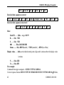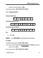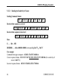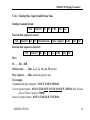
1
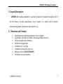
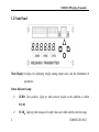
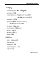
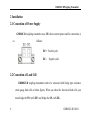
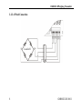
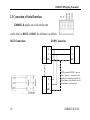
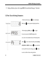
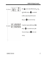
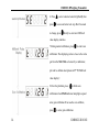
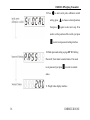
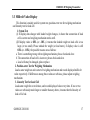
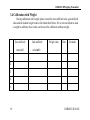
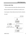
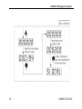
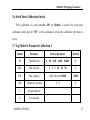
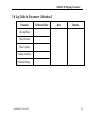
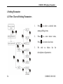
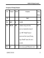
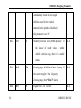
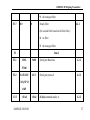
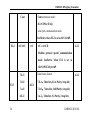
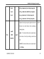
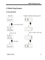
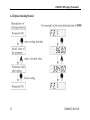
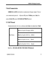
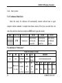
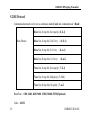
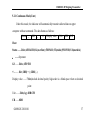
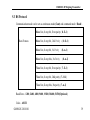
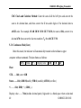
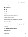
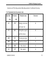
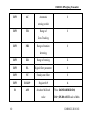
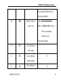
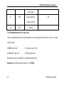
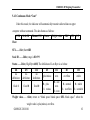
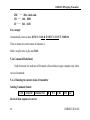
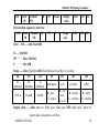
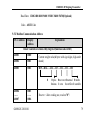
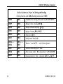
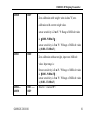
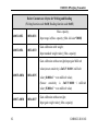
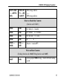
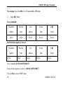
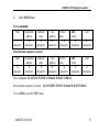
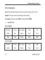
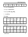
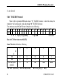
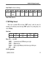
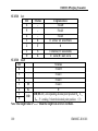
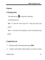
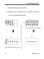
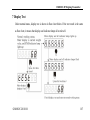
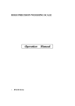
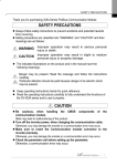
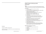
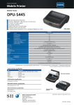
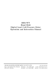
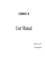
GM8802C-D User Manual GM8802C-D110101 48010224231000 CONTENTS 1 General Description .................................................................................................. 1 1.1 Functions and Features....................................................................................... 1 1.2 Front Panel ......................................................................................................... 2 1.3 Technical Specifications..................................................................................... 3 1.4 Dimensions ........................................................................................................ 5 2 Installation ................................................................................................................ 6 2.1 Connection of Power Supply ............................................................................. 6 2.2 Connection of Load Cell .................................................................................... 6 2.3 Connection of Serial Interface........................................................................ 100 3 Calibration .............................................................................................................. 11 3.1 Descriptions of Calibration .............................................................................. 61 3.2 Flow Chart of Setting Parameters .................................................................. 122 3.3 Millivolt Value Display .................................................................................... 17 3.4 Calibration with Weight ................................................................................... 18 3.5 Calibration without Weight .............................................................................. 19 3.6 Serial Ports Calibration Switch ...................................................................... 211 3.7 Log Table for Parameter Calibration 1 ........................................................... 231 3.8 Log Table for Parameter Calibration 2 ........................................................... 233 4 Setting Parameter ..............................................................................................244 4.1 Flow Chart of Setting Parameters ...............................................................244 4.2 Method of Setting Parameters ....................................................................311 5 Serial Communication .......................................................................................333 5.1 EASY Protocol .............................................................................................33 5.2 RE Protocol ..................................................................................................36 5.3 RS Protocol ..................................................................................................39 5.4 SP1 Protocol .................................................................................................58 5.5 Modbus Protocol ..........................................................................................77 5.6 tt TOLEDO Protocol ....................................................................................98 5.7 RDP Philips Protocol....................................................................................99 6 Operation ...........................................................................................................101 6.1 Zeroing Operation .....................................................................................101 6.2 Inputting Password ....................................................................................101 6.3 Setting Password .......................................................................................103 6.4 Recover Initial Settings .............................................................................103 7 Display Test .......................................................................................................107 8 Errors and Alarm Messages ...............................................................................108 GM8802C-D Weighing Transmitter 1 General Description GM8802C-D weighing transmitter is specially designed for industrial weighing field. It has the features of steady characteristics, easy to operate. It is widely used in concrete, bitumen mixing plants, blast furnace and converter, etc.. 1.1 Functions and Features Small dimension, handsome appearance, easy to operate. Applicable to all kinds of resistance strain gauge bridge load cell. Front panel numerical calibration Multilevel of digital filter Automatic zero –tracking Automatic zeroing when power up Bothway serial port(RS-232/RS-485) Calibration via serial interface GM8802C-D110101 1 GM8802C-DWeighing Transmitter 1.2 Front Panel Main Display: 6 digits, for displaying weight, analog output value, and the information of parameters. Status Indicator Lamp: ZERO: Zero position. Light up when present weight on the platform is within 0±1/4d. 2 STAB:Light up when changes of weight values are within stability criterion range. GM8802C-D110101 GM8802C-D Weighing Transmitter DATA: Light up when data transmission. Keypad: key to zeroing and exit from the current function status. key to choose the parameter items. key to choose the functions of parameter setting. key to enter items (when setting parameters or calibration) or confirm the current function. 1.3 Technical Specifications 1.3.1 General Specifications: Power supply :DC24V ± 5% Working temperatures :-10~40℃ Humidity :90% R.H without dew Power :about 4W Dimension :82×92×45(mm) GM8802C-D110101 3 GM8802C-DWeighing Transmitter 1.3.2 Analog Part: Load cell exciting voltage :DC5V 200mA(MAX) Input resistance :10MΩ Zero point adjustment range:0.2~8mV when the sensor is 2mV/V; 0.02~12mV when the sensor is 3mV/V; Input sensitivity :0.1uV/d Input range:0.2~10.5mV (when the sensor is 2mV/V) 0.02~15mV(when the sensor is 3mV/V) A/D conversion: Sigma - Delta A/D conversion speed:120times/second Non-linear :0.01% F.S Gain drifting :10PPM/℃ Precision:1/30000 1.3.3 Digital Part: Display :6 high light red LEDs Negative data display :“-” Overflow display:“OFL” Position of decimal point :5 options Keypad:4 beep keys 4 GM8802C-D110101 GM8802C-D Weighing Transmitter 1.4 Dimensions Dimension of front panel: Length:82mm Width:92mm Hight:45mm GM8802C-D110101 5 GM8802C-DWeighing Transmitter 2 Installation 2.1 Connection of Power Supply GM880C-D weighing transmitter uses 24V direct-current power and the connection is as follows: DC+: Positive pole DC-: Negative pole 2.2 Connection of Load Cell GM8802C-D weighing transmitter need to be connected with bridge type resistance strain gauge load cells as below figures. When you chose the four-wired load cells, you must bridge the SN+ with EX+ and bridge the SN- with EX-. 6 GM8802C-D110101 GM8802C-D Weighing Transmitter The signal definition of each port of the load cell connector as follows: Port EX+ SN+ EX- SN- SIG+ SIG- AGI Connection Excitation+ Sense+ Excitation- Sense- Signal+ Signal- Shield 2.2.1 6-Wired Connection Load cell GM8802C-D110101 7 GM8802C-DWeighing Transmitter 2.2.2 4-Wired Connection Load cell 8 GM8802C-D110101 GM8802C-D Weighing Transmitter 1. The signals from the load cells are low voltage analog signals, which are easily affected by electro-noise, so the cables connecting load cells to indicator should use shielded cables, and not bind with other cables, especially power supply cables. 2. For the application of short-transporting-distance and lower precision, 4-wired connection can be used; otherwise, 6-wired should be used. 3. For the application of multi-load cell in parallel connection, the sensitivity of each load cell (mV/V) must be same. GM8802C-D110101 9 GM8802C-DWeighing Transmitter 2.3 Connection of Serial Interface GM8802C-D supplies one serial interface that can be chosen as RS232 or RS485. The definition is as follows: RS232 Connection:: re ll o rt n o C RS485 Connection: A 1 n re ll o rt n o C A B B GND GND . . . A B ert u p m o C GND is ground of RS485, it can very much improve communication quality via connecting with GND by low-resistance wire when there is a lot of disturbance in working field. GND 10 GM8802C-D110101 GM8802C-D Weighing Transmitter 3 Calibration 3.1 Descriptions of Calibration (1)Calibration procedure must be executed when a GM8802C-D weighing transmitter is put in use at the first time, the preset parameters may no longer meet the user’s needs, and any part of the weighing system was changed. Position of decimal point, minimum division, maximum capacity, zero, and gain can be set and confirmed through calibration. (2)If you want to skip one parameter to next one, press one parameter, please press directly; If you want to set only to save your desired value and then press to return normal working status. (3)Please refer to page 21“3.7 Log Table for Parameter Calibration 1” for details. (4)During calibration, please make record in page 23 “3.8 Log Table for Parameter Calibration 2” for later urgent situation. GM8802C-D110101 11 GM8802C-DWeighing Transmitter (5)During calibration, please refer to page108“8. Error and Alarm Messages” for details. 3.2 Flow Chart of Setting Parameters 1.Under normal status, press CAL, press twice, then display to enter password inputting interface. 2.When displaying PASS, press , then input the correct password, CAL ON displayed for one second , then automatically enter Decimal position 3.Press to select a desired decimal position(0、0.0、 0.00、0.000 or 0.0000), then press to save and enter next step. But if no need to change, press directly to enter next Min. division setting interface. 12 GM8802C-D110101 GM8802C-D Weighing Transmitter 4.Press to select a desired Min. division (1、2、5、 10、20 or 50), then press to save and enter next Max. capacity setting. But if no need to change, press directly to enter next step. 5. Input Max. Capacity(≤Min.Division×30000), then press to save and enter next step. But if no need to change, press directly to enter next step. GM8802C-D110101 13 GM8802C-DWeighing Transmitter 6. Press press to select a desired sensitivity(2 or3), then to save and enter next step. But if no need to change, press directly to enter next Millivolt value display interface. 7.During normal calibration, press to enter zero calibration. The displaying value is close to the value got from the SIG+/SIG- of sensor by a multimeter, pls refer to definite descriptions in 17 “3.3 Millivolt value display”. 8.Clear the platform, press to finish zero calibration when STAB indicator lamp lights up and enter gain calibration.If no need to zero calibrate, press 14 to enter gain calibration. GM8802C-D110101 GM8802C-D Weighing Transmitter Follow the below flow chart, then you can finish gain calibration and enter password setting. If no need to gain calibrate, just press GM8802C-D110101 to enter next password setting interface. 15 GM8802C-DWeighing Transmitter 9.Press to enter serial ports calibration switch setting, press then press to choose a desired position, again to enter next step. If no need to set the position of the switch ,just press to enter next password setting interface. 10.Finish password setting as page103 “6.3 Setting Password”, then return to normal status. If no need to set password, just press to return to normal status.. 11. Weight value display interface. 16 GM8802C-D110101 GM8802C-D Weighing Transmitter 3.3 Millivolt Value Display This function is mainly used for system test, position-error test for weighing mechanism and linearity test for load cell. 1. System Test (1) If display data changes with loaded weight changes, it shows that connection of load cell is correct and weighing mechanism works well. (2)If display value is OFL (or –OFL), it means that loaded weight on load cells is too large (or too small). Please unload the weight (or load more), if display value is still OFL (or –OFL), the possible reasons are as follows: a. There is something wrong with weighing mechanism, please check and clear. b. The connection of load cell is incorrect, please check and clear. c. Load cells may be damaged, please replace. 2. Position-error Test for Weighing Mechanism Load a same weight on each corner of weighing mechanism and record displayed millivolt value respectively. If differences among these values are obvious, please adjust weighing mechanism. 3. Linearity Test for Load Cell Load same weight for several times, and record displayed value every time. If one or two values are obviously much larger or smaller than any others, it means that the linearity of load cell is bad. GM8802C-D110101 17 GM8802C-DWeighing Transmitter 3.4 Calibration with Weight During calibration with weight, please record the zero millivolt value, gain millivolt value and the loaded weight value in the blank table below. If it is not convenient to load a weight to calibrate, these values can be used for calibration without weight. Zero millivolt Gain millivolt value(mV) value(mV) Weight value Date Remarks 1 2 3 4 5 18 GM8802C-D110101 GM8802C-D Weighing Transmitter 3.5 Calibration without Weight When it is not convenient to load a weight to calibrate, calibration can be done without weight using recorded data in the table in section 3.8. However, this method is just used for some emergencies, it will make calibration result incorrect if load cells, or indicator has been replaced. GM8802C-D110101 19 GM8802C-DWeighing Transmitter 20 GM8802C-D110101 GM8802C-D Weighing Transmitter 3.6 Serial Ports Calibration Switch When calibration via serial ports(rS、SP1 or Modbus) is needed, the serial ports calibration switch must be “ON”, or the command of serial ports calibration will return to errors. 3.7 Log Table for Parameter Calibration 1 Symbol Parameter Value of parameter Default Pt Decimal Point 0 0.0 0.00 0.000 0.0000 0 1d= Min. Division 1 2 5 10 20 50 1 CP Max. Capacity ≤Min. Division*30000 10000 SE Sensitivity of sensor 2 3 2 t System millivolt o Zero position GM8802C-D110101 21 GM8802C-DWeighing Transmitter C Gain SIOCAL Serial ports calibration switch PASS 22 Password Setting 000000 GM8802C-D110101 GM8802C-D Weighing Transmitter 3.8 Log Table for Parameter Calibration 2 Parameter Calibrated Value Data Remarks Decimal Point Min. Division Max. Capacity Sensor sensitivity Password Setting GM8802C-D110101 23 GM8802C-DWeighing Transmitter 4 Setting Parameter 4.1 Flow Chart of Setting Parameters 1. Press to select a desired item among sibling items; 2. Press Press 3. Pls to enter minor terms, to return to last item; refer to below list for descriptions of parameters. 24 GM8802C-D110101 GM8802C-D Weighing Transmitter Descriptions of Working Parameters NO. Parameter Default Descriptions Setting Method F1 Item 1 F1.1 00~99 01 Scale ID 4.2.1 F1.2 OFF/ON OFF Automatic zeroing switch when 4.2.2 power up. Automatically zeroing if it is set “ON”. “Error2” Alarms if current value>Max. Capacity*Zeroing range; “Error3” Alarms if the scale is not stable. F1.3 0-9 GM8802C-D110101 0 Zero-tracking range(0~9d optional): used to 4.2.1 25 GM8802C-DWeighing Transmitter automatically check the zero slight drifting caused by the residual material on the platform. Disabled if this parameter is set “0”. F1.4 1-9 1 Stability criterion range(1~9d optional):: If 4.2.1 the change of weight value is within stability criterion rang, then it is a stable status. F1.5 0-99 50 Zeroing range: 0%-99% of Max. Capacity. If 4.2.1 the current weight > Max. Capacity* Zeroing range, then“Error2” alarms. F1.6 26 0-9 5 Digital filter:0:no filter; 4.2.1 GM8802C-D110101 GM8802C-D Weighing Transmitter 9:the strongest filter F1.7 0-9 Steady filter 0 4.2.1 (the second filter based on the first filter): 0:no filter; 9:the strongest filter F2 F2.1 Item 2 1200~ 9600 Serial port Baud rate 4.2.2 bUS Serial port protocol 4.2.2 rEAd rEAd(command mode) or 4.2.2 57600 F2.2 rS/rE/bUS/ EASy/SP1/t t/rdP F2.3 rEAd/ GM8802C-D110101 27 GM8802C-DWeighing Transmitter Cont continuous mode) Cont rE(rS/SP1or EASy) serial port communication mode. Ineffective when F2.2 is set as bUS /tt/rdP. F2.4 rtU/ASC rtU rtU or ASCII; 4.2.2 Modbus protocol special communication mode. Ineffective when F2.2 is set as rE/rS/SP1/EASy/tt/rdP. Data frames format: 7-E-1/ 7-E-1:7data bits, Even Parity, 1stop bit; 7-O-1/ 8-E-1 F2.5 28 4.2.2 7-n-2/ 7-O-1:7 data bits, Odd Parity, 1stop bit; 8-E-1/ 7-n-2:7data bits, No Parity, 2 stop bits; GM8802C-D110101 GM8802C-D Weighing Transmitter 8-O-1/ 8-E-1:8data bits, Even Parity,1stop bit; 8-n-1/ 8-O-1:8data bits, Odd Parity,1stop bit; 8-n-2 8-n-1:8data bits, No Parity,1stop bit; 8-n-2:8 data bits, No Parity,2stop bits; Option of serial port speed, adjust the interval 4.2.2 between two data frames when continuous sending datas. nonE/ nonE:The interval between two data frames F2.6 10/20/ nonE is the time of next byte during current baud 30/40/50 rate. 10~50:The interval between two data frames is 10~50ms. GM8802C-D110101 29 GM8802C-DWeighing Transmitter F3 Item 3 9 registers available for users,use system F3.1~ 000000~ F3.9 999999 000000 4.2.1 decimal point to display. Read-write through keys or serial ports(ModBus/RS/SP1). F4 F4.1 F4.2 Item 4 OFF/ON OFF Switch for parameter password setting 4.2.2 000000 Setting parameter password:Effective when 6.3 F4.1=ON 30 GM8802C-D110101 GM8802C-D Weighing Transmitter 4.2 Method of Setting Parameters 4.2.1 Data Input Method GM8802C-D110101 31 GM8802C-DWeighing Transmitter 4.2.2Option Selecting Method 32 GM8802C-D110101 GM8802C-D Weighing Transmitter 5 Serial Communication GM8802C-D has RS232 serial interface to communicate with upper computer. There are seven communication protocols: :rS protocol /rE protocol /Modbus protocol (bus)/ fast protocol (EASy)/SP1 protocol /tt TOLEDO/rdP PHILIPS protocol. 5.1 EASY Protocol Communication mode can be set as continuous mode(Cont) and command mode(Read). 8data bits, 1 stop bit, Even parity ( 8- E-1) Data Frames: 8data bits, 1 stop bit, Odd Parity ( 8- O-1) 8data bits, 1 stop bit, No Parity 8data bits, 2 stop bits, No Parity (8- n-1) (8- n-2) Baud Rate:1200, 2400, 4800, 9600, 19200, 38400, 56700(Optional) GM8802C-D110101 33 GM8802C-DWeighing Transmitter Code:binary system 5.1.1 Continuous Mode(Cont) Under this mode, the indicator will automatically transmit collected data to upper computer without command. A complete data frame consists of five bytes: one mark byte; one status byte and three data bytes(compressed BCD code, high-order ahead). Data Mark byte Status byte Description FFH Status byte BCD1 Main display: the first and second bit BCD2 Main display: the third and fourth bit BCD3 Main display: the fifth and sixth bit The definition of “Status byte”: D7 no Fixed:0 34 Status byte(binary system) D4 D3 D2D1D0 Plus/ zero overflow stable current decimal position minus 100 011 010 001 000 0: 0: 0: 0:not zero normal stable plus 4bits 3bits 2bits 1bit 0bit 1:zero 1: 1: 1: overflow unstable minus GM8802C-D110101 D6 D5 GM8802C-D Weighing Transmitter For example: When the transmitter sends out a hexadecimal data as below: Data frames: FF 03 00 12 34 Refer to above data frame form, we know the data of main display is 1234, the status byte is 03( refer to “The definition of “Status byte”, the corresponding hexadecimal data is 00000011), then we know current status is: not zero, normal , stable, plus, current decimal point is the third bit. 5.1.2 Command Mode(Read) Under this mode, the indicator will transmit collected data to upper computer only when received command. Data Description R 52H CR 0DH CF 0AH Response from the indicator: The data frame is just the same as that when Continuous Mode . GM8802C-D110101 35 GM8802C-DWeighing Transmitter 5.2 RE Protocol Communication mode can be set as continuous mode(Cont) and command mode(Read). 8data bits, 1 stop bit, Even parity ( 8- E-1) Data Frames: 8data bits, 1 stop bit, Odd Parity ( 8- O-1) 8data bits, 1 stop bit, No Parity 8data bits, 2 stop bits, No Parity (8- n-1) (8- n-2) 7data bits, 1 stop bit, Even parity ( 7- E-1) 7data bits, 1 stop bit, Odd parity ( 7- O-1) 7data bits, 2 stop bits, No parity ( 7- n-2) Baud Rate:1200, 2400, 4800, 9600, 19200, 38400, 56700(Optional) Code:ASCII 36 GM8802C-D110101 GM8802C-D Weighing Transmitter 5.2.1 Continuous Mode(Cont) Under this mode, the indicator will automatically transmit collected data to upper computer without command. The data frames as follows: Status , GS , +/- Display value Unit CR LF Here: Status ——2bits; 4FH 4CH;OL(overflow);53H 54H; ST(stable);55H 53H; US(unstable) , ——Separator GS ——2bits; 47H 53H +/- ——1bit; 2BH( + ) ; 2DH( - ) Display value ——7 bits(include decimal point); high-order is a blank space when no decimal point Unit ——2bits; kg; 4BH 67H CR ——0DH GM8802C-D110101 37 GM8802C-DWeighing Transmitter LF ——0AH For example: When the transmitter sends out a date sequence as below: 53 54 2C 47 53 2C 2B 30 31 31 2E 31 32 30 4B 67 0D 0A Then we know the current status of indicator is: Stable; data is positive number; current weight value is11.120kg 5.2.2 Command Mode(Read) Under this mode, the indicator will transmit collected data to upper computer only when received command. Data Description R 52H E 45H A 41H D 44H CR 0DH LF 0AH Response from the indicator: The data frame is just the same as that of RE protocol’s Continuous Mode . 38 GM8802C-D110101 GM8802C-D Weighing Transmitter 5.3 RS Protocol Communication mode can be set as continuous mode(Cont) and command mode(Read). 8data bits, 1 stop bit, Even parity ( 8- E-1) Data Frames: 8data bits, 1 stop bit, Odd Parity ( 8- O-1) 8data bits, 1 stop bit, No Parity 8data bits, 2 stop bits, No Parity (8- n-1) (8- n-2) 7data bits, 1 stop bit, Even parity ( 7- E-1) 7data bits, 1 stop bit, Odd parity ( 7- O-1) 7data bits, 2 stop bits, No parity ( 7- n-2) Baud Rate:1200, 2400, 4800, 9600, 19200, 38400, 56700(Optional) Code:ASCII GM8802C-D110101 39 GM8802C-DWeighing Transmitter CRC Check and Calculate Method: Count the sum of all the left bytes and convert the sum to be decimal date, and then convert the 2 low-order digits of the decimal date to ASCII code. For example, 02 4D 2B 30 31 30 2E 37 36 30, the sum is 1D6, convert it to decimal 470, then convert the last two numbers 7、0 to ASCII 37 30. 5.3.1 Continuous Mode(Cont) Under this mode, the indicator will automatically transmit collected data to upper computer without command. The data frames as follows: STX Status +/- Display value CRC CR LF Here: STX——1 bit; start : 02H Status ——1bit; 4DH:M(stable); 53H:S(unstable); 4FH:O(overflow) +/- ——1bit; 2BH( + ) ; 2DH( - ) Display value ——7 bits(include decimal point); high-order is a blank space when no decimal 40 GM8802C-D110101 GM8802C-D Weighing Transmitter point CRC ——2 bits, check sum CR ——0DH LF ——0AH For example: When the transmitter automatically returns to the below data: 02 4D 2B 30 31 30 2E 37 36 30 37 30 0D 0A Then we know current status is: stable, plus, and current weight value is 10.760. 5.3.2 Command Mode(Read) Under this mode, the indicator will transmit collected data to upper computer only when received command. 5.3.2.1 Reading the Current Status of GM8802C-D Sending Command format: GM8802C-D110101 41 GM8802C-DWeighing Transmitter STX Scale ID R S CRC CR LF Received data sequence is correct: STX Scale ID R S 000 Status Display value CRC CR LF Received data sequence is incorrect: STX Scale ID R S N O CRC CR LF Here: Scale ID —— 2bits,range: 00~99 R —— 1bit,52H S —— 1bit,53H 000 —— 3bits, 30H 30H 30H Status —— 1bit, 4DH:M(stable);53H:S(unstable);4FH:O(overflow) Display value—— 6bits, not include decimal point, high-order is minus when the display value is minus. N —— 1bit, 4EH O—— 1bit, 4FH For example: Command from upper computer:02 30 31 52 53 36 34 0D 0A Correct response format:02 30 31 52 53 30 30 30 4D 2D 30 32 32 35 35 38 34 0D 0A(1# Scale, 42 GM8802C-D110101 GM8802C-D Weighing Transmitter stable status, current main display is -2.255) Incorrect response format:02 30 31 52 53 4E 4F 32 31 0D 0A 5.3.2.2 Reading Decimal Point Sending Command format: STX Scale ID R P CRC CR LF CRC CR Received data sequence is correct: STX Scale ID R P DDDDDD LF Received data sequence is incorrect: STX Scale ID R P N O CRC CR LF Here: P —— 1bit,50H DDDDDD—— 6bits, 000000~000004 corresponding 0~4 decimal point positions. For example: Command from upper computer:02 30 31 52 50 36 31 0D 0A Correct response format:02 30 31 52 50 30 30 30 30 30 33 35 32 0D 0A (decimal point position is 3, that is 0.000 ) Incorrect response format:02 30 31 52 50 4E 4F 31 38 0D 0A GM8802C-D110101 43 GM8802C-DWeighing Transmitter 5.3.2.3 Reading the Sensitivity of Sensor Sending Command format: STX Scale ID R E CRC CR LF CRC CR Received data sequence is correct: STX Scale ID R E DDDDDD LF Received data sequence is incorrect: STX Scale ID R E N O CRC CR LF Here: E—— 1bit,45H DDDDDD—— 6bits, 000000~000001 corresponding 2mV/V、3mV/V. For example: Command from upper computer:02 30 31 52 45 35 30 0D 0A Correct response format:02 30 31 52 45 30 30 30 30 30 30 33 38 0D 0A (the sensitivity of sensor is 2mV/V ) Incorrect response format:02 30 31 52 45 4E 4F 30 37 0D 0A 44 GM8802C-D110101 GM8802C-D Weighing Transmitter 5.3.2.4 Reading Max. Capacity and Division Value Sending Command format: STX Scale ID R M CRC CR LF Received data sequence is correct: STX Scale ID R M Division value Max. Capacity CRC CR LF Received data sequence is incorrect: STX Scale ID R M N O CRC CR LF Here: M —— 1bit,4DH Division value —— 2bits, 1、2、5、10、20、50 optional Max. Capacity—— 6bits, maximum capacity value For example: Command from upper computer:02 30 31 52 4D 35 38 0D 0A Correct response format:02 30 31 52 4D 30 35 30 35 30 30 30 30 35 32 0D 0A (Min. division value is 5, Max. Capacity is 50000) Incorrect response format:02 30 31 52 4D 4E 4F 31 35 0D 0A GM8802C-D110101 45 GM8802C-DWeighing Transmitter 5.3.2.5 Reading the Working Parameters Sending Command format: STX Scale ID R F Working parameter 0 CRC CR LF CRC CR Received data sequence is correct: STX Scale ID R F Working parameter 0 DDDDDD LF Received data sequence is incorrect: STX Scale ID R F N O CRC CR LF Here: F —— 1bit,46H Working parameter —— 2 bits, confirm the working parameter according to current data DDDDDD—— 6bits, current working parameter value For example: Command from upper computer:02 30 31 52 46 31 34 30 30 30 0D 0A Correct response format:02 30 31 52 46 31 34 30 30 30 30 30 30 35 39 33 0D 0A (Working parameter 1.4: range of motion detecting is 5) Incorrect response format:02 30 31 52 46 4E 4F 30 38 0D 0A 46 GM8802C-D110101 GM8802C-D Weighing Transmitter 5.3.2.6 Serial Zeroing Function Sending Command format: STX Scale ID C C CRC C O K CR LF Received data sequence is correct: STX Scale ID C CRC CR LF STX Scale ID C C N O CRC Here: C —— 1bit, 43H K —— 1bit, 4BH For example: Command from upper computer:02 30 31 43 43 33 33 0D 0A Correct response format:02 30 31 43 43 4F 4B 38 37 0D 0A Incorrect response format:02 30 31 43 43 4E 4F 39 30 0D 0A CR LF Received data sequence is incorrect: 5.3.2.7 Calibration 1 . Calibration the Decimal Point Position Sending Command format: GM8802C-D110101 47 GM8802C-DWeighing Transmitter STX Scale ID C P Decimal point position CRC CR LF Received data sequence is correct: STX Scale ID C P O K CRC CR LF STX Scale ID C P N O CRC Here: P —— 1bit, 50H Decimal point position —— 1bit, range 0~4 For example: Command from upper computer:02 30 31 43 43 33 33 0D 0A Correct response format:02 30 31 43 43 4F 4B 38 37 0D 0A Incorrect response format:02 30 31 43 43 4E 4F 39 30 0D 0A CR LF Received data sequence is incorrect: 2 . Calibration the Division value and Max. Capacity Sending Command format: STX Scale ID C M Division value Max. Capacity CRC CR LF Received data sequence is correct: STX 48 Scale ID C M O K CRC CR LF GM8802C-D110101 GM8802C-D Weighing Transmitter Received data sequence is incorrect: STX Scale ID C M N O CRC CR LF Here: M —— 1bit, 4DH Division value —— 2bits, writing Min. division value (1、2、5、10、20、50) Max. Capacity —— 6bits, writing Max. Capacity For example: Command from upper computer:02 30 31 43 4D 30 35 30 31 34 30 30 30 33 37 0D 0A (Writing data:division value is 5,Max. capacity is 14000) Correct response format:02 30 31 43 4D 4F 4B 39 37 0D 0A Incorrect response format:02 30 31 43 4D 4E 4F 30 30 0D 0A 3 . Calibration the Sensitivity of Sensor Sending Command format: STX Scale ID C E Sensitivity of Sensor CRC CR CR LF LF Received data sequence is correct: STX Scale ID C E O K CRC Received data sequence is incorrect: GM8802C-D110101 49 GM8802C-DWeighing Transmitter STX Scale ID C E N O CRC CR LF Here: E —— 1bit, 45H Sensitivity of Sensor —— 1bit, range 0~1 For example: Command from upper computer:02 30 31 43 45 30 38 33 0D 0A(Writing data:sensitivity of sensor is 0, that is 2mV/V) Correct response format:02 30 31 43 45 4F 4B 38 39 0D 0A Incorrect response format:02 30 31 43 45 4E 4F 39 32 0D 0A 4 . Zero Calibration 1) Zero Calibration with Standard Weight Sending Command format: STX Scale ID C Z CRC CR LF Z O K CRC CR Z N O CRC CR Received data sequence is correct: STX Scale ID C LF Received data sequence is incorrect: STX 50 Scale ID C LF GM8802C-D110101 GM8802C-D Weighing Transmitter Here: Z —— 1bit, 5AH For example: Command from upper computer:02 30 31 43 5A 35 36 0D 0A Correct response format:02 30 31 43 5A 4F 4B 31 30 0D 0A Incorrect response format:02 30 31 43 5A 4E 4F 31 33 0D 0A 2) Zero Calibration without Standard Weight Sending Command format: STX Scale ID C Y Zero millivolt value CRC CR LF Received data sequence is correct: STX Scale ID C Y O K CRC CR LF Y N O CRC CR LF Received data sequence is incorrect: STX Scale ID C Here: Y —— 1bit, 59H Zero millivolt value —— 6bits; For example: GM8802C-D110101 51 GM8802C-DWeighing Transmitter Command from upper computer:02 30 31 43 59 30 30 31 32 36 31 35 33 0D 0A(Writing data: zero millivolt value is 1.261) Correct response format:02 30 31 43 59 4F 4B 30 39 0D 0A Incorrect response format:02 30 31 43 59 4E 4F 31 32 0D 0A 5. Gain Calibration 1) Zero Calibration with Standard Weight Add a standard weight approaching 80% of the Max. capacity ,then write in the current value of the standard weight to finish gain calibration. Sending Command format: STX Scale ID C G Weight value CRC CR LF Received data sequence is correct: STX Scale ID C G O K CRC CR LF G N O CRC CR LF Received data sequence is incorrect: STX Scale ID C Here: G —— 1bit, 47H 52 GM8802C-D110101 GM8802C-D Weighing Transmitter Weight value —— 6bits; write in the standard weight value For example: Command from upper computer:02 30 31 43 47 30 30 30 32 30 30 32 37 0D 0A(writing data: the weight value is 200) Correct response format:02 30 31 43 47 4F 4B 39 31 0D 0A Incorrect response format:02 30 31 43 47 4E 4F 39 34 0D 0A 2) Zero Calibration without Standard Weight Input the standard weight value in Appendix and the corresponding gain Millivolt value to finish gain calibration. Sending Command format: STX Scale ID C L Millivolt value Weight value CRC CR LF Received data sequence is correct: STX Scale ID C L O K CRC CR LF L N O CRC CR LF Received data sequence is incorrect: STX Scale ID C Here: GM8802C-D110101 53 GM8802C-DWeighing Transmitter L —— 1bit, 4CH Millivolt value —— 6bits; corresponding gain millivolt value of current weight value Weight value —— 6bits; standard weight value For example: Command from upper computer:02 30 31 43 4C 30 30 30 31 39 34 30 30 30 32 30 30 33 34 0D 0A(writing data: the weight value is 200, corresponding gain millivolt value is 0.194) Correct response format:02 30 31 43 4C 4F 4B 39 36 0D 0A Incorrect response format:02 30 31 43 4C 4E 4F 39 39 0D 0A 5.3.2.8 Writing Working Parameter Sending Command format: STX Scale ID W F Working parameter item 0 Parameter value CRC CR LF Received data sequence is correct: STX Scale ID W F O K CRC CR LF F N O CRC CR LF Received data sequence is incorrect: STX Scale ID W Here: W —— 1bit, 57H 54 GM8802C-D110101 GM8802C-D Weighing Transmitter F —— 1bit, 46H Working parameter value —— 2bits; confirm the working parameter item according to current data Parameter value —— 6bits; write-in the parameter value For example: Command from upper computer:02 30 31 57 46 31 34 30 30 30 30 30 30 35 39 38 0D 0A (write-in range of motion detecting F1.4 is 5) Correct response format:02 30 31 57 46 4F 4B 31 30 0D 0A Incorrect response format:02 30 31 57 46 4E 4F 31 33 0D 0A 5.3.2.9 Reading Register 1-9 Sending Command format: STX Scale ID R R Parameter 0 CRC CR LF CRC CR Received data sequence is correct: STX Scale ID R R Parameter 0 DDDDDD LF Received data sequence is incorrect: STX Here: GM8802C-D110101 Scale ID R R N O CRC CR LF 55 GM8802C-DWeighing Transmitter Parameter —— 2bits; 33H 31H--33H 39H(represents reading F3.1--F3.9) DDDDDD —— 6bits; parameter value of register For example: Command from upper computer:02 30 31 52 52 33 31 30 31 31 0D 0A(reading F3.1) Correct response format:02 30 31 52 52 33 31 30 30 30 30 35 30 30 30 34 0D 0A Incorrect response format:02 30 31 52 52 4E 4F 32 30 0D 0A 5.3.2.10 Writing Register 1-9 Sending Command format: STX Scale ID W R Parameter 0 DDDDDD CRC CR LF Received data sequence is correct: STX Scale ID W R O K CRC CR LF Received data sequence is incorrect: STX Scale ID W R N O CRC CR LF Here: Parameter —— 2bits; 33H 31H--33H 39H(represents reading F3.1--F3.9) DDDDDD —— 6bits; parameter value of register For example: 56 GM8802C-D110101 GM8802C-D Weighing Transmitter Command from upper computer:02 30 31 57 52 33 31 30 30 30 30 35 30 30 30 39 0D 0A (writing F3.1 “500”) Correct response format:02 30 31 57 52 4F 4B 32 32 0D 0A Incorrect response format:02 30 31 57 52 4E 4F 32 35 0D 0A 5.3.3 CRC (Check sum) Count of RS Protocol Count the sum of all the left bytes and convert the sum to a decimal data, and then convert the last 2 low-order digits of the decimal date to ASCII code.. For example: See below data frame: 02 30 31 43 47 4F 4B 39 31 0D 0A Check bit The sum:187(Hex) 391(decimal data) ※Then work out: the check code of the above data frame is :39 31 GM8802C-D110101 57 GM8802C-DWeighing Transmitter 5.4 SP1 Protocol Communication mode can be set as continuous mode(Cont) and command mode(Read). 8data bits, 1 stop bit, Even parity ( 8- E-1) Data Frames: 8data bits, 1 stop bit, Odd Parity ( 8- O-1) 8data bits, 1 stop bit, No Parity 8data bits, 2 stop bits, No Parity (8- n-1) (8- n-2) 7data bits, 1 stop bit, Even parity ( 7- E-1) 7data bits, 1 stop bit, Odd parity ( 7- O-1) 7data bits, 2 stop bits, No parity ( 7- n-2) Baud Rate:1200, 2400, 4800, 9600, 19200, 38400, 56700(Optional) Code:ASCII 58 GM8802C-D110101 GM8802C-D Weighing Transmitter Operation code: W, writing operation; R, reading operation; C, calibration; O, zeroing 5.4.1 Explanation form for parameter code Operation Parameter code R Parameter name Characters Reading current status 8 code WT and weight value W DC Writing Max. capacity 8 and Min. division R/W PT Decimal point digits 1 R/W SE Sensitivity of sensor 1 R DD Min. division 2 R CP Max. capacity 6 GM8802C-D110101 59 GM8802C-DWeighing Transmitter R/W AC Automatic 1 zeroing switch R/W TR Range of 1 Zero-Tracking R/W MR Range of motion 1 detecting R/W ZR Range of zeroing 2 R/W FL Digital filter parameter 1 R/W VC Steady state filter 1 R/W R 1-R 9 Register 1-9 6 R AM Absolute Millivolt value 60 7bits: D6D5D4D3D2D1D0; D6:+;D5-D0:ASCII code of 6bits GM8802C-D110101 GM8802C-D Weighing Transmitter corresponding Millivolt value Decimal point:4bits R RM Millivolt value of relative zero 7bits: D6D5D4D3D2D1D0; D6:+/ - ;D5-D0: ASCII code of 6bits corresponding Millivolt value; Decimal point:4bits C ZY Zero calibration with weight C ZN Zero calibration 6 without weight C GY GM8802C-D110101 Gain calibration 6 61 GM8802C-DWeighing Transmitter with weight C GN Gain calibration 12 without weight O CZ Zeroing 5.4.2 Explanation form for wrong code Under communication mode, if the transmitter received wrong data frame, there will be a wrong code as below: 1.CRC check error 2. Operation code error 3.Parameter code error 4.Writing data error 5.Operation can’t be performed 6.channel number error Remark: the default channel number is: 1(31H) 62 GM8802C-D110101 GM8802C-D Weighing Transmitter 5.4.3 Continuous Mode “Cont” Under this mode, the indicator will automatically transmit collected data to upper computer without command. The data frames as follows: STX Scale ID Channel NO Status Weight value CRC CR LF Here: STX——1bit; Start:02H Scale ID ——2bits; range is 00~99 Status ——2bits; High Byte:40H; The definition of Low Byte is as below: D6 no definition D5 no definition D4 no definition fixed:1 fixed:0 fixed:0 D3 D2 D1 D0 plus/minus zero overflow stable 0:plus 1:minus 0:not zero 1:zero 0:normal 1:overflow 0:stable 1:unstable Weight value—— 6bits; return to “blank space blank space OFL blank space” when the weight value is plus(minus) overflow. GM8802C-D110101 63 GM8802C-DWeighing Transmitter CRC —— 2bits, check sum CR —— 1bit,0DH LF —— 1bit,0AH For example: Automatically return to data: 02 30 31 31 40 40 30 30 32 31 36 35 37 38 0D 0A Then we know the current status of indicator is: Stable; weight value is plus and 2.165. 5.4.4 Command Mode(Read) Under this mode, the indicator will transmit collected data to upper computer only when received command. 5.4..4.1 Reading the current status of transmitter Sending Command format: STX Scale ID Channel NO. R WT CRC CR LF Received data sequence is correct: 64 GM8802C-D110101 GM8802C-D Weighing Transmitter STX Scale ID Channel NO. R WT Status Display value CRC CR LF Received data sequence is incorrect: STX Scale ID Channel NO. R WT E Wrong code CRC CR LF Here: STX——1bit; Start:02H R ——1bit;52H WT —— 2bits; 57H 54H E —— 1bit; 45H Status ——2bits; High Byte:40H; The definition of Low Byte is as below: D6 no definition D5 no definition D4 no definition fixed:1 fixed:0 fixed:0 D3 D2 D1 D0 plus/minus zero overflow stable 0:plus 1:minus 0:not zero 1:zero 0:normal 1:overflow 0:stable 1:unstable Display value—— 6bits; return to “blank space blank space OFL blank space” when the weight value is plus(minus) overflow. GM8802C-D110101 65 GM8802C-DWeighing Transmitter Wrong code —— 2bits; refer to the explanation for wrong code For example: Command from upper computer:02 30 31 31 52 57 54 30 31 0D 0A Correct response format:02 30 31 31 52 57 54 40 40 30 30 30 31 33 32 32 33 0D 0A(stable status, current main display is 0.132) Incorrect response format:02 30 31 31 52 57 54 45 31 31 39 0D 0A 5.4.4.2 Reading other Parameter Sending Command format: STX Scale ID Channel NO. R Parameter code CRC CR LF Received data sequence is correct: STX Scale ID Channel NO. R Parameter code Parameter value Parameter code E CRC CR LF Received data sequence is incorrect: STX Scale ID Channel NO. R Wrong code CRC CR LF Parameter value——1 bit; Parameter code——2 bits, refer to the explanations of parameters, input corresponding codes, 66 GM8802C-D110101 GM8802C-D Weighing Transmitter for example, if need to read range of motion detecting, then input corresponding parameter code MR(4DH 52H). For example: Command from upper computer:02 30 31 31 52 4D 52 38 39 0D 0A Correct response format:02 30 31 31 52 4D 52 35 34 32 0D 0A (range of motion detecting: 5) Incorrect response format:02 30 31 31 52 4D 52 45 31 30 37 0D 0A 5.4.4.3 Writing Max. Capacity and Min. Division Sending Command format: STX Scale ID Channel NO. W DC Division value Max. capacity CRC CR LF Received data sequence is correct: STX Scale ID Channel NO. W DC O K CRC CR LF Received data sequence is incorrect: STX Scale ID Channel NO. Here: DC —— 2bits, 44H 43H GM8802C-D110101 W DC E Wrong code CRC CR LF 67 GM8802C-DWeighing Transmitter O —— 1bit, 4FH K —— 1bit, 4BH Division value——2bits, 1/2/5/10/20/50 Max. capacity——6bits, write-in Max. capacity value For example: Command from upper computer:02 30 31 31 57 44 43 30 35 30 31 30 30 30 30 36 30 0D 0A (division value is 5;Max. capacity is 10000) Correct response format:02 30 31 31 57 44 43 4F 4B 32 34 0D 0A Incorrect response format:02 30 31 31 57 44 43 45 35 39 32 0D 0A 5.4.4.4 Writing Max. Capacity and Min. Division Sending Command format: STX Scale ID Channel NO. W Parameter code Parameter value CRC CR LF Received data sequence is correct: STX Scale ID Channel NO. W Parameter code O K CRC CR LF CRC CR LF Received data sequence is incorrect: STX 68 Scale ID Channel NO. W Parameter code E Wrong code GM8802C-D110101 GM8802C-D Weighing Transmitter For example: Command from upper computer:02 30 31 31 57 5A 52 35 30 30 38 0D 0A(write-in zeroing range “50”) Correct response format:02 30 31 31 57 5A 52 4F 4B 36 31 0D 0A Incorrect response format:02 30 31 31 57 5A 52 45 31 32 35 0D 0A 5.4.4.5 Zero Calibration 1) Zero Calibration with Standard Weight Sending Command format: STX Scale ID Channel NO. C ZY CRC CR LF Received data sequence is correct: STX Scale ID Channel NO. C ZY O K CRC CR LF Received data sequence is incorrect: STX Scale ID Channel NO. Here: Z —— 1bit, 5AH Y —— 1bit, 59H For example: GM8802C-D110101 C ZY E Wrong code CRC CR LF 69 GM8802C-DWeighing Transmitter Command from upper computer:02 30 31 31 43 5A 59 39 34 0D 0A Correct response format:02 30 31 31 43 5A 59 4F 4B 34 38 0D 0A Incorrect response format:02 30 31 31 43 5A 59 45 35 31 36 0D 0A 2) Zero Calibration without Standard Weight Sending Command format: STX Scale ID Channel NO. C ZN Zero millivolt CRC CR LF Received data sequence is correct: STX Scale ID Channel NO. C ZN O K CRC CR LF Received data sequence is incorrect: STX Scale ID Channel NO. C ZN E Wrong code Here: ZN —— 2bits, 5AH 4EH Zero millivolt —— 6bits, decimal point fixed: 4. CRC CR LF For example: Command from upper computer:02 30 31 31 43 5A 4E 30 31 32 36 31 30 38 31 0D 0A Correct response format:02 30 31 31 43 5A 4E 4F 4B 33 37 0D 0A Incorrect response format:02 30 31 31 4D 5A 4E 45 32 31 32 0D 0A 70 GM8802C-D110101 GM8802C-D Weighing Transmitter 5.4.4.6 Gain Calibration 1) Gain Calibration with Standard Weight Add a standard weight approaching 80% of the Max. capacity ,then write in the current value of the standard weight to finish gain calibration. Sending Command format: STX Scale ID Channel NO. C GY Weight value CRC CR LF Received data sequence is correct: STX Scale ID Channel NO. C GY O K CRC CR LF Received data sequence is incorrect: STX Scale ID Channel NO. C GY E Wrong code Here: GY —— 2bits, 47H 59H Weight value —— 6bits:write-in the standard weight value CRC CR LF For example: Command from upper computer:02 30 31 31 43 47 59 30 30 30 32 30 30 36 35 0D 0A(writing data: weight value is 200) GM8802C-D110101 71 GM8802C-DWeighing Transmitter Correct response format:02 30 31 31 43 47 59 4F 4B 32 39 0D 0A Incorrect response format:02 30 31 32 43 47 59 45 36 39 39 0D 0A 2) Gain Calibration without Standard Weight Input the standard weight value in Appendix and the corresponding gain Millivolt value to finish gain calibration. Sending Command format: STX Scale ID Channel NO. C GN Gain millivolt Weight value CRC CR LF Received data sequence is correct: STX Scale ID Channel NO. C GN O K CRC CR LF Received data sequence is incorrect: STX Scale ID Channel NO. C GN E Wrong code CRC CR LF Here: Gain millivolt —— 6bits, corresponding gain millivolt value of standard weight (decimal point fixed:4) Weight value—— 6bits, the standard weight value For example: 72 GM8802C-D110101 GM8802C-D Weighing Transmitter Command from upper computer:02 30 31 31 43 47 4E 30 30 31 39 34 30 30 30 30 32 30 30 35 36 0D 0A(Writing data:weight value is 200,corresponding gain millivolt is 0.194) Correct response format:02 30 31 31 43 47 4E 4F 4B 31 38 0D 0A Incorrect response format:02 30 31 31 43 5A 52 45 33 30 37 0D 0A 5.4.4.7 Zeroing Operation Sending Command format: STX Scale ID Channel NO. O CZ CRC CR LF Received data sequence is correct: STX Scale ID Channel NO. O CZ O K CRC CR LF Wrong code CRC CR LF Received data sequence is incorrect: STX Scale ID Channel NO. O CZ E For example: Command from upper computer:02 30 31 31 4F 43 5A 38 34 0D 0A Correct response format:02 30 31 31 4F 43 5A 4F 4B 33 38 0D 0A Incorrect response format:02 30 31 31 4F 43 5A 45 35 30 36 0D 0A GM8802C-D110101 73 GM8802C-DWeighing Transmitter 5.4.4.8 Reading Register 1-9 Sending Command format: STX Scale ID R Parameter code CRC CR LF CRC CR Received data sequence is correct: STX Scale ID R Parameter code DDDDDD LF Received data sequence is incorrect: STX Scale ID R Parameter code N O CRC CR LF Here: Parameter code —— 2bits, R1—R9,refer to parameter address of registers to write-in parameter codes, for example, write-in register F3.3, then the parameter code is R3(52H 33H) For example: Command from upper computer:02 30 31 52 52 31 31 32 0D 0A(reading register F3.1) Correct response format:02 30 31 52 52 31 30 30 30 35 30 30 30 35 0D 0A Incorrect response format:02 30 31 52 52 31 4E 4F 36 39 0D 0A 74 GM8802C-D110101 GM8802C-D Weighing Transmitter 5.4.4.9 Writing Register 1-9 Sending Command format: STX Scale ID W Parameter code DDDDDD CRC CR LF Received data sequence is correct: STX Scale ID W Parameter code O K CRC CR LF Received data sequence is incorrect: STX Scale ID W Parameter code N O CRC CR LF Here: Parameter code —— 2bits, R1—R9,refer to parameter address of registers to write-in parameter codes, for example, write-in register F3.3, then the parameter code is R3(52H 33H) For example: Command from upper computer:02 30 31 57 52 31 30 30 30 35 30 30 30 31 0D 0A (writing register F3.1:500) Correct response format:02 30 31 57 52 31 4F 4B 37 31 0D 0A Incorrect response format:02 30 31 57 52 31 4E 4F 37 34 0D 0A GM8802C-D110101 75 GM8802C-DWeighing Transmitter 5.4.4.10 CRC Count Count the sum of all the left bytes and convert the sum to be a decimal data, and then convert the last 2 low-order digits of the decimal date to ASCII code. For example: See below data frame: 02 30 31 31 4F 43 5A 38 34 0D 0A Check bit The sum:180(Hex) 384(decimal data) ※Then w ork out:the check code of the above data fram e is :38 34 76 GM8802C-D110101 GM8802C-D Weighing Transmitter ■5.5 Modbus Protocol 5.5.1 Modbus Communication Mode RTU Mode Under this mode, every 8-bit byte of the message are divided into 2pcs of 4-bit hexadecimal characters to transmit at binary code. The data frame as below: 8data bits, 1 stop bit, Even parity ( 8- E-1) Data Frames: 8data bits, 1 stop bit, Odd Parity ( 8- O-1) 8data bits, 1 stop bit, No Parity (8- n-1) 8data bits, 2 stop bit, No Parity (8- n-2) Baud Rate:1200/2400/4800/ 9600/ 19200/ 38400/ 56700(Optional) GM8802C-D110101 77 GM8802C-DWeighing Transmitter Code:binary system ASCII Mode Under this mode, every 8-bit byte is transmitted as 2 pcs of ASCII characters. The data frame: 8data bits, 1 stop bit, Even parity ( 8- E-1) 8data bits, 1 stop bit, Odd Parity ( 8- O-1) Data 8data bits, 1 stop bit, No Parity (8- n-1) 8data bits, 2 stop bit, No Parity (8- n-2) Frames: 7 data bits, 1 stop bit, Even parity ( 7- E-1) 7 data bits, 1 stop bit, Odd parity ( 7 - O-1) 7 data bits, 2 stop bit, No Parity 78 (7- n-2) GM8802C-D110101 GM8802C-D Weighing Transmitter Baud Rate:1200/2400/4800/ 9600/ 19200/ 38400/ 56700(Optional) Code:ASCII Code 5.5.2 Modbus Communication Address PLC address Display Explanation address Below Contents are Read-Only Register(function code is0x03) 40001 0000 40002 0001 Current weight value(4 bytes with sign digits, high-order ahead) 40003 0002 D15—D14……D4 — D3 — D2 — D1 — D0 0 40004 …... 40007 0003 …… 0006 GM8802C-D110101 0:plus 0:not zero 0:normal 0:stable 1:minus 1:zero 1:overflow 1:unstable Reserve(allow reading out, read out”0”) 79 GM8802C-DWeighing Transmitter Below Contents are 2 bytes for Writing and Reading (Writing function code: 0x06) Reading function code: 0x03) 80 40008 40009 0007 0008 Automatically zeroing when power on ( 0: OFF;1:ON) ( ) Range of Zero-Tracking(0-9) 40010 40011 0009 0010 Range of motion detecting(1-9) 40012 40013 0011 0012 40014…… 40016 40017 40018 0013…… 0015 0016 0017 40019 0018 Range of zeroing(0%-99%) Filter Level (0-9) Steady status filter (0-9) Reserve(read out”0”, only for later update) Position of decimal point(0- 4) Min. division value( 0-5;represents: 1/ 2/ 5/ 10/ 20/ 50) Sensor sensitivity(0-1;represents: 2mV/V、3mV/V) GM8802C-D110101 GM8802C-D Weighing Transmitter 40020 0019 Zero calibration with weight: write-in data”1”,zero calibration with current weight value. sensor sensitivity is 2 m V / V: Range of Millivolt value is(0.000- 9.000mV); sensor sensitivity is 3 m V / V:Range of Millivolt value is (0.000- 13.000mV); 40021 0020 Zero calibration without weight, input zero Millivolt value. Input range is: Sensor sensitivity is 2 m V / V:Range of Millivolt value is(0.001- 9.000mV); sensor sensitivity is 3 m V / V:Range of Millivolt value is (0.001- 13.000mV) 40022… 40030 0021…… 0029 GM8802C-D110101 Reserve(read out”0”) 81 GM8802C-DWeighing Transmitter Below Contents are 4 bytes for Writing and Reading (Writing function code: 0x10; Reading function code: 0x03) 40031-0032 0030-0031 40033-0034 0032-0033 Max. capacity; Input range is(Max. capacity ≤Min. division*30000) Gain calibration with weight; Input standard weight value(≤ Max. capacity) Gain calibration without weight;Input gain Millivolt value(sensor sensitivity is 2mV/V:0.000<millivolt 40035-40036 0034-0035 value≤10.000mV-zero millivolt value); (Sensor sensitivity is 3mV/V:0.000 < millivolt value≤15.000mV-zero millivolt value) 40037-40038 82 0036-0037 Gain calibration without weight; Input gain weight value(≤ Max. capacity) GM8802C-D110101 GM8802C-D Weighing Transmitter 40039-40040 ……40055-4 0056 00038-000 39……000 54-00055 F3.1 storage address …… F3.9 storage address Below are Read-Only Contents (function code: 0 x 0 1 ) 00041 0040 0:Stable; 1:Unstable 00042 0041 0:Normal; 1:Overflow 00043 00044 0042 0043 0:Not zero; 1:Zero; 0:‘ + ’;; 1:‘ - ’ 00045….. 00056 0044….. 0055 Reserve(read out”0”) Write and Read Contents (Reading function code: 0x01;Writing function code: 0x05) 00057 0056 GM8802C-D110101 Zeroing.(input FF00:zeroing) ; return to 0 when reading coil 0 83 GM8802C-DWeighing Transmitter 5.5.3 Explanation of Function Code There are 5 function codes in above Modbus communication protocol:01 Reading the status of the coil;03 Reading holding register; 05 Force single coil;;06 Preset single holding register; 16 (10 Hex) preset multiple holding registers. 01 Reading the Status of the Coil Query: Query information assigns the starting coil and the quantity of coil. Response: (1) Each status of the coil corresponds to each data: 1=ON;0=OFF. The LSB(Least Significant Bit)of the first byte is the start address during query, the other coils are arranged from low bit to high bit till the eighth coil, the next byte is also arranged from low bit to high bit. (2) If the return coil is not the multiple of 8,then set “0”for the bits from the rest bits of the last bits to the highest bit ,the byte district represents all the byte number. 84 GM8802C-D110101 GM8802C-D Weighing Transmitter For example: Request to read 40 43 coil from Transmitter 01 1) Under RTU Mode for communication: Query command: Transmitter Function Start The Number Address Code Address of Coils 1 byte 1 byte 2 bytes 2 bytes CRC Check 2 bytes Received data sequence is correct: Transmitter Function Counting Data Address Code Byte District 1 byte 1 byte 1 byte 1 byte CRC Check 2 bytes Query command: 01 01 00 28 00 04 BD C1 Received data sequence is correct: 01 01 01 02 D0 49 The corresponding status of coil 43 40: 0 0 1 0 GM8802C-D110101 85 GM8802C-DWeighing Transmitter 2) Under ASCII Mode for communication: Query command: Start Transmitter Function Start TheNumber LRC Address Code Address of Coils Check End 1 2 2 4 4 2 2 character characters characters characters characters characters characters End Received data sequence is correct: Start Transmitter Function Counting Data LRC Address Code Byte District Check 1 2 2 2 2 2 2 character characters characters characters characters characters characters Query command: 3A 30 31 30 31 30 30 32 38 30 30 30 34 44 32 0D 0A Received data sequence is correct: 3A 30 31 30 31 30 31 30 32 46 42 0D 0A 86 GM8802C-D110101 GM8802C-D Weighing Transmitter The corresponding status of coil 43 40: 0 0 1 0 03 Reading Register Status Query: uery information assigns the start address and number of the registers. Response:Response information assigns the byte number of the reading register, each register corresponds to 2 bytes; there is also the data value of each reading register in the response information. For example: Reading register 0007、0008 1) Under RTU Mode: Query command: Transmitter Function Start Address Code Address 1 byte 1 byte GM8802C-D110101 2 bytes Query the number of CRC Check Registers 2 bytes 2 bytes 87 GM8802C-DWeighing Transmitter Received data sequence is correct: Transmitter Function Counting Register0007 Register0008 CRC Address Code Byte Data Data Check 1byte 1byte 1byte 2bytes 2bytes 2bytes Query command:01 03 00 07 00 02 75 CA Received data sequence is correct:01 03 04 00 00 00 05 3A 30 The data for Register 0007and Register 0008:0(Hex:0000H)、5(Hex:0005H) 2) Under ASCII Mode: Query command: Start Transmitter Function Start Query the LRC Address Address Code Address number of Check End Registers 88 GM8802C-D110101 GM8802C-D Weighing Transmitter 1 2 2 4 4 2 2 character characters characters characters characters characters characters Received data sequence is correct: Start 1 character Transmitter address 2 characters Function code 2 characters Counting byte 4 characters Register 0007 4 characters Register 0008 2 characters LRC Check 2 characters End 2 characters Query command:3A 30 31 30 33 30 30 30 37 30 30 30 32 46 33 0D 0A Received data sequence is correct:3A 30 31 30 33 30 34 30 30 30 30 30 30 30 35 46 33 0D 0A The data for Register 0007and Register 0008: :0(Hex:0000H)、5(Hex:0005H) 05 Force single coil Query: Query information assigns the address of the coil that need to be forced;A constant in query data district the ON/OFF status for the requested coil: FF00 value for ON status,0000H value for OFF status. Other value is ineffective to the coils. Response: The coil being force status returns to normal response. GM8802C-D110101 89 GM8802C-DWeighing Transmitter For example: Force the 0056 coil of Transmitter01 is ON status 1) Under RTU Mode: Force command: Transmitter Function Coil Forced CRC Address Code Address Data Check 1 byte 1 byte 2 bytes 2 bytes 2 bytes Received data sequence is correct: Transmitter Function Coil Forced CRC Address Code Address Data Check 1 byte 1 byte 2 bytes 2 bytes 2 bytes Force command: 01 05 00 38 FF 00 0D F7 Received data sequence is correct:01 05 00 38 FF 00 0D F7 The coil 056 is set to be “ON” status. 90 GM8802C-D110101 GM8802C-D Weighing Transmitter 2) Under ASCII Mode: Force command: Start 1 character Transmitter address 2 characters Function code 2 characters Coil address 4 characters Forced data 4 characters LRC check 2 characters Coil address 4 characters Forced data 4 characters LRC check 2 characters End 2 characters Received data sequence is correct: Start 1 character Transmitter address 2 characters Function code 2 characters End 2 characters Force command: 3A 30 31 30 35 30 30 33 38 46 46 30 30 43 33 0D 0A Received data sequence is correct:3A 30 31 30 35 30 30 33 38 46 46 30 30 43 33 0D 0A The coil 056 is set to be “ON” status. GM8802C-D110101 91 GM8802C-DWeighing Transmitter 06 Preset Single Register Preset: Preset information assigns the address and value of the register need to be preset. Response: The register returns to normal response after presetting. For example: Please preset register 0009 of transmitter NO.1 to 0005H. 1) Under RTU Mode: Preset command: Transmitter Function Preset Register Preset CRC Address Code Address Value Check 1 byte 1 byte 2 bytes 2 bytes 2 bytes Transmitter Function Preset Register Preset CRC Address Code Address Value Check Correct response: 92 GM8802C-D110101 GM8802C-D Weighing Transmitter 1 byte 1 byte 2 bytes 2 bytes 2 bytes Preset command:01 06 00 09 00 05 99 CB Correct response:01 06 00 09 00 05 99 CB The value of register 0009 is 5(Hex:0005H) 2) Under ASCII Mode: Preset command: Start Transmitter address Function code 1 character 2 characters 2 characters Preset register address 4 characters Preset value LRC check 4 characters 2 characters Preset register address 4 characters Forced data LRC check 4 characters 2 characters End 2 characters Correct response: Start Transmitter address Function code 1 character 2 characters 2 characters GM8802C-D110101 End 2 characters 93 GM8802C-DWeighing Transmitter Preset command:3A 30 31 30 36 30 30 30 39 30 30 30 35 45 42 0D 0A Correct response:3A 30 31 30 36 30 30 30 39 30 30 30 35 45 42 0D 0A The value of register 0009 is 5(Hex:0005H) 16(10 hex) Preset Multiple Registers Preset: Preset information assigns the start address and value of the register need to be preset. Response: Normal response and return to the transmitter address、function code、start address and the number of preset registers. For example: Put preset value into 2 registers of Transmitter NO.1,the start register is 0030, preset values are 0001H and 7318H. 1) Under RTU Mode: Transmitter address 1byte Function code 1byte Start address 2bytes The number of registers 2bytes Counting byte 1byte Preset value 4bytes CRC check 2bytes Correct response: 94 GM8802C-D110101 GM8802C-D Weighing Transmitter Transmitter address 1byte Function code 1byte Start address 2bytes The number of registers 2bytes CRC check 2bytes Preset command:01 10 00 1E 00 02 04 00 01 73 18 07 D5 Correct response:01 10 00 1E 00 02 21 CE 2) Under ASCII Mode: Start 1 characte r Transmitter address 2 Character s Function code 2 Character s Start address 4 charact ers The number of registers 4 character s Counting byte 2 character s Preset value 8 character s LRC check 2 character s END 2 character s Correct response: Start Transmitter Function Start The number END LRC address code address of registers check 1 2 2 4 4 2 2 character characters characters characters characters characters characters Preset command:3A 30 31 31 30 30 30 31 45 30 30 30 32 30 34 30 30 30 31 31 43 39 36 31 38 0D 0A GM8802C-D110101 95 GM8802C-DWeighing Transmitter Correct response:3A 30 31 31 30 30 30 31 45 30 30 30 32 43 46 0D 0A 5.5.4 Error Message under Modbus Communication The transmitter sends message back to the host when detected error except check code (CRC or LRC) . The highest bit of function code is “1”, It means that the function code which is sent by transmitter is 128 more than the function code which is sent by host(for example: reading register command,03H will be changed to 83H) Abnormal code: 02: illegal data address; the received data address is the unallowed address of transmitter. 03: illegal data; the value of query data field is the unallowed value of transmitter. For example: The upper computer reads coil (0040)using function code 03. The data frame of error message: 1) 96 Under RTU mode: GM8802C-D110101 GM8802C-D Weighing Transmitter Transmitter address 1byte 2) Function code 1byte Abnormal code 1byte CRC check 2bytes Under ASCII mode: Start 1byte Transmitter address 2bytes Function code 2bytes Abnormal code 2bytes LRC check 2bytes END 2bytes For example: The upper computer reads coil (0040)using function code 03. 1) Under RTU mode: Query command: 01 03 00 28 00 01 04 02 The response of receiving data incorrectly: 01 83 02 C0 F1 2) Under ASCII mode: Query command: 3A 30 31 30 33 30 30 32 38 30 30 30 31 44 33 0D 0A The response of receiving data incorrectly: 3A 30 31 38 33 30 32 37 41 0D 0A Refer to the data frames, the current wrong code is 02. The current data address is illegal means GM8802C-D110101 97 GM8802C-DWeighing Transmitter it’s not allowed. 5.6 tt TOLEDO Protocol Please refer to parameter F2.2 and choose “tt” TOLEDO protocol,under this status, the transmitter will continuously sends data trough “tt” TOLEDO protocol. The continuous mode “Cont” format of tt protocol as following: 1 2 3 4 5 6 7 8 9 10 11 12 13 14 15 16 17 18 STX CR ︸ A B C Display weight(6bits) 6 pcs 30H check sum Here: ASCII Start character:02(STX) Status Word A is defined as following: 0 1 0 1 0 1 0 .x 0 1 .xx 0 1 .xxx 1 1 .xxxx D 0 D1 1 D2 0 Decimal point x position D3 D5 : 1(invariant) D4 98 D6: 0(invariant) D7: Even parity ( 7 E-1) GM8802C-D110101 GM8802C-D Weighing Transmitter Status Word B is defined as following: D7 D6 Even parity Transmitter status D5 D4 Unit D3 Stable D2 Overflow D1 Sign D0 G/N.W Status Word C(Reserve) 5.7 RDP Philips Protocol Please refer to parameter F2.2 and choose “RDP” protocol,under this status, the transmitter will continuously sends data trough “RDP” protocol. Every sending delay is the value of F2.6(ms). Data frame: STX 1 MODE 1 STATU 1+1 Weight 6 ETX 1 Here:STX —— Start: 02H MODE —— Communication mode, 31H means gross weight. STATU —— 2Byte status byte. Weight —— Display weight: 6 bits, may include minus sign or blank space. ETX —— 03H STATUS explanation: GM8802C-D110101 99 GM8802C-DWeighing Transmitter STATUS 1 st: Bit 6 5 4 3 2 1 0 Status E T S Z E xpl a na ti on Fixed 0 Fixed 1 Fixed 1 1: error or overflow 0 1:stable;0: unstable 1: zero;0: not zero STATUS 2 nd: Bit Status Fixed 0 6 Fixed 1 5 Fixed 1 4 Fixed 1 3 M 2 K 0 1 D D (0 0 - 11 ) corresponding decimal point position: 0 、 1 、 DD 0 2 、 3 (sending 3 when the decimal point position ﹥3 ) Note: The weight value is“------” when the weight is in error or overflows . 100 GM8802C-D110101 GM8802C-D Weighing Transmitter 6 Operation 6.1 Zeroing Operation Under normal status, press to zeroing the data on main-display . Errors alarm during zeroing: "Error 2": alarms when “current weight value”> “zeroing range” during zeroing operation; "Error 3":alarms when current weight display or system is not stable during zeroing operation. 6.2 Inputting Password (1) The initial password for calibration and parameter setting is 000000. (2) According to relevant standard, calibrated parameters are protected by password, GM8802C-D110101 101 GM8802C-DWeighing Transmitter calibration password must be input before calibration. (3)During parameter setting, if F4.1(password switch is set as“ON”,.password must be input when entering parameter setting interface. 102 GM8802C-D110101 GM8802C-D Weighing Transmitter Note: (1)During inputting password, if the password your entered for the first time is incorrect, GM8802C-D weighing transmitter will return to the second inputting password interface, but the display will turn to from . (2)If the password your entered for the second time is incorrect, GM8802C-D weighing transmitter will return to the third inputting password interface, but the display will turn to from . (3)If the password your entered for the third time is still incorrect, GM8802C-D will display "Error 4" and enter self-locking status, then you must power up again to operation. 6.3 Setting Password (1)There are “setting parameter” items both during calibration and working parameters, if need to set password during working parameters, the F4.1(password switch) must be “ON”. (2)During setting password, password can be set successfully only when the new password is GM8802C-D110101 103 GM8802C-DWeighing Transmitter input twice and the two inputting passwords are same; If the two inputting passwords are not same, the GM8802C-D will display "Error" for one second, then return to password setting interface(PASS). 104 GM8802C-D110101 GM8802C-D Weighing Transmitter 6.4 Recover Initial Settings Note: Recover initial settings means that recover all parameters’ settings to initial value, this operation may leads to abnormal working of GM8802C-D transmitter, so please don’t operate except professional person! For example( recover all parameter settings): 1.Under normal working status, press one time to display SET UP, then meanwhile press and to display‘PASS’on the main-display. 2.When displaying“PASS”, press to enter password setting status. 3. Input the special password“ 880202”for recovering initial settings. Press and to set values, then press to save password and enter recovering working parameters interface. 4. On this interface, press to switchover the content need to be recovered. 5. Calibrate the interface of parameter recovering: ; Press on the interface of parameter recovering, then return to normal working interface. GM8802C-D110101 105 GM8802C-DWeighing Transmitter ※After recovering operation, all parameter values will turn to initial values. ※Press if you want to abandon recovering operation and return to weighing status. Note: 1) Under “F SET”interface, press to recover working parameter settings. start recovering initial settings. 2) Under “F CAL” interface, press 3) Under “F ALL” interface, press 106 to recover parameter calibration. to recover all parameter settings. GM8802C-D110101 GM8802C-D Weighing Transmitter 7 Display Test Under normal status, display test is shown in flow chart below. If the test result is the same as flow chart, it means that display and indicator lamps all work well. GM8802C-D110101 107 GM8802C-DWeighing Transmitter 8 Errors and Alarm Messages Error ①Input error. ②Incorrect data input, please check the corresponding parameter range. Error 2 The current weight is not within the zeroing range when zeroing. Error 3 The current weight value display (system) is not stable when zeroing. Error 4 Password input is incorrect for 3 times. OFL Weighing result is positive overflow. -OFL Weighing result is negative overflow. OVER The output signal of load cell is too large while doing zero calibration. UNDER The output signal of load cell is too small while doing zero calibration. 108 GM8802C-D110101