1
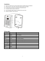
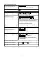
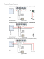
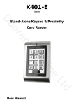
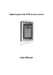
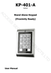
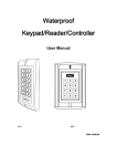
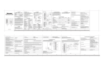
KP-KR3 Stand-Alone Keypad & Proximity Card Reader User Manual INTRODUCTION The KP-KR3 is a two relay multifunction standalone access control keypad suitable for either indoor or outdoor use It is housed in a strong, sturdy and vandal resistant Zinc Alloy electroplated case. The electronics are fully potted making it extremely weather resistant and conforming to IP68 It supports up to 1200 users in a Card, PIN, or a Card + PIN option. The inbuilt card reader supports 125KHZ EM frequency card or key fob, and the Pin length is 4-8 digits Both of the two relays can operate in Pulse Mode (suitable for access control) or Toggle Mode (suitable for arming/disarming alarms, switching lights, machines….etc) The R3K has many extra features including block enrollment, backlit keypad. These features make the R3K an ideal choice for door access not only for small shops and domestic households but also for commercial and industrial applications such as factories, warehouses, laboratories, banks and prisons Features Weather resistant to IP68 Strong Zinc Alloy Electroplated anti-vandal case Two relay operation Both relays can be programmed for 3 modes: Card, PIN, Card + PIN 1200 user capacity Zone 1: up to 1100 Pin & Card holders, Zone 2: up to 100 Pin & Card holders Pin length: 4-8 digits; card type: 125KHZ EM card/key fob Can be used as a standalone keypad Pulse mode, Toggle mode Block enrollment, can enroll 1100 consecutive cards within 2 minutes Backlit keypad Adjustable Door Relay Output time, Alarm time, Door Open time Built in light dependent resistor (LDR) for anti-tamper Built in buzzer Dual relay outputs for door opening, door status detecting, open door by button Red, Yellow and Green LEDS display the working status Supports door bell connection (For relay 2) 12-24V AC/DC power input 2 Specifications Operating Voltage 12-24V AC/DC User Capacity 1200 Keypad 12 keys, 3 x 4 digits Card Type EM card/key fob Card Reading Distance 3-6 cm Pin length 4-8 digits Active Current <60mA Idle Current 25±5 mA Lock Output Load Max 2A Alarm Output Load Max 20A Operating Temperature -25-60℃ Operating Humidity 5%- 95% RH Environment Conforms to IP68 Adjustable Door Relay time 1 -99 seconds Adjustable Alarm Time 0- 3 minutes Wiring Connections Electric Lock, Exit Button, DOTL, External Alarm Dimensions H: 128 x W: 82 x D: 28 mm Net Weight 650g Gross Weight 800g Packing List Name Quantity Remarks Digital Keypad-R3K 1 User manual 1 Screw driver 1 Rubber bungs 4 6*27mm, used for fixing Self tapping screws 4 3.5*27mm, used for fixing Please ensure that all the above contents are correct. If any are missing please notify the supplier of the KP-KR3 3 Installation Remove the back cover from the keypad using the supplied security screwdriver Drill four holes on the wall for the screws and one hole for the cable Fix the back cover firmly on the wall with 4 flat head screws Thread the cable through the cable hole Use the supplied rubber bungs to waterproof the screw holes Attach the keypad to the back cover Wiring cable Color Function Description Grey & Black GND Negative pole Grey Alarm - Alarm Negative Yellow & Black OPEN2 Request to Exit Button of Zone 2 Yellow OPEN1 Request to Exit Button of Zone 1 Brown D_IN Door status detecting Red AC & DC AC & DC 12-24V power input Black AC & DC AC & DC 12-24V power input Blue & Black NO 2 Black & White COM2 Green & Black NC 2 Blue NO1 White COM1 Green NC1 4 Quick Programming Guide To enter the programming mode * Master code # 888888 is the default factory master code To exit from the programming mode * Note that to undertake the following programming the master user must be logged in To change the master code 0 New code # New code # The master code must be 6 digits To add a PIN user for Zone 1 1 User ID number (1-1100) # To add a Pin user for Zone 2 1 User ID number (1101-1200) # PIN # PIN # The ID number is any number between 1 & 1100 for Zone 1 and any number between 1101 & 1200 for Zone 2 The PIN is any 4-8 digits between 0000 & 99999999 with the exception of 1234 which is reserved Users can be added continuously without exiting programming mode To add a card user for Zone 1 1 Read Card # To add a card User for Zone 2 5 Read Card # Cards can be added continuously without exiting programming mode To delete a PIN or a card user 2 User ID number 2 Read Card # # for a PIN user or for a card user Users can be deleted continuously without exiting programming mode To Unlock the door for Zone 1 or Zone 2 To unlock the door for a PIN user Enter the PIN then press # To unlock the door for a card user Present the card 5 Connection Diagram Examples Common power supply for magnetic lock (Fail open – power to lock) Common power supply for lock release (Fail secure – power to unlock) Common power supply for auto gate controller (using Normally Open contact) 6 Remarks: the Zone 2, it can be used to operate a doorbell if there is no need to operate a second door. The wiring to connect the doorbell is via NO2 and COM2. Press #, the R3K will send out a switching signal to the doorbell, as long as you press the” #”, the doorbell will operate, it will stop when you release the ” #” Relay operation (Pulse mode and Toggle mode) Both of the two relays can operate in Pulse Mode (suitable for access control) or Toggle Mode (suitable for arming/disarming alarms, switching lights, machines….etc) Every time a valid fob/card or Pin is read/input in Pulse Mode, the relay will operate for the pre-set relay pulse time Every time a valid fob/card or Pin is read/input in Toggle Mode, the relay changes state and will not turn back until the fob/card is presented or the PIN used Anti-Tamper Alarm The R3K uses an LDR (light dependent resistor) as an anti tamper alarm. If the keypad is removed from the cover then the tamper alarm will operate Sound and LED indication Operation Status Red LED Green LED Blue LED Buzzer Zone 1, unlock - Bright - Short Ring Zone 2, unlock - - Bright Short Ring Power on Bright - Stand by Shines slowly Off - - Press keypad - - - Short Ring Operation successful - Bright - Long Ring Operation failed - - - 3 Short Rings Enter into programming mode Bright off - Long Ring In the programming mode Bright Bright - - Exit from the programming mode Shines slowly - - Long Ring Alarm Shines quickly - - Alarm 7 Long Ring KP-KR3 Detailed Programming Guide User Settings To enter the programming * mode Master code # 888888 is the default factory master code To exit from the programming * mode Note that to undertake the following programming, the master user must be logged in To change the master code 0 New code # Repeat new code # The master code could be any 6 digits number Setting the working mode: 3 Set valid Card or PIN users 1 3 2 2 # 2 , Zone 1 # , Zone 2 Entry is by either Card or PIN (Factory default setting) 3 Set valid Card and PIN users 1 3 1 2 # 1 , Zone 1 # , Zone 2 Entry is by Card and PIN together Note: When adding users, if the Card or Pin user has been enrolled already, you can not add it again. The R3K will give a bleep as error Factory default setting: Card or PIN mode To set users for Zone 1. ( To add PIN users 3 1 1 2 #) User ID number # PIN # The ID number is any number among 1 - 1100 The PIN is any 4-8 digits between 0000 - 99999999 with the exception of 1234 which is reserved. Users can be added continuously without exiting programming mode as follows: To delete PIN users 1 User ID no 1 # 2 User ID number PIN # User ID no 2 # PIN # # Users can be deleted continuously without exiting programming mode To change the PIN of a PIN * ID number # Old PIN # user (Note: This step must be done out of programming mode) 8 New PIN # Repeat new PIN # To add Card Users. (Method 1 Read card # 1) Card can be added continuously without exiting programming mode This is an easy way to enter cards with auto-generated ID numbers The ID number will start from 1 if no user has been programmed To add Card Users. (Method 1 2) ID number # Card # The ID number can be any number among 1 - 1100 This is the alternative way to enter cards using User ID Allocation. In this method a User ID is allocated to a card Only one user ID can be allocated to a single card To add a series cards users 5 – Block Enrollment ID number # 8 digits Card number # Card quantity # Card quantity is between 1-1100 The card number must be Of the 8 digits card number, it is the last 8 digits on the card consecutive (This operation is only for Zone 1) To delete Card users by 2 Read Card # cards The device can automatically identify the card of Zone 1 or Zone 2 Note: Users can be deleted continuously without exiting programming mode To delete Card users by user 2 User ID # ID This option can be used when a user has lost their card To delete card users by card 9 number Input 8 digits Card number # Cards can be deleted continuously without exiting from programming mode To set users for Zone 2. ( 3 2 2 #) To set Pin user for Zone 2 is the same as Zone 1, only the ID number is 1101-1200 for Zone 2. To set Card user for Zone 2 is the same as Zone 1, with the exception of adding Card users with auto-generated ID numbers (Method 1) as below 9 To add Card Users. (Method 5 Read Card # 1) Card can be added continuously without exiting programming mode Auto-generated ID numbers Card and PIN Mode To set users for Zone 1. ( 3 1 1 #) To Add a card and Pin user Add the card as for a card user (The PIN is any four digits Press between 0000 & 99999999 Then allocate the card a PIN as follows: with the exception of 1234 which is reserved.) To change a PIN in card and * to exit from the programming mode * Read card 1234 # PIN # PIN # * Read Card * ID number # 2 Read Card Old PIN # New PIN # New PIN # PIN mode (Method 1) Note that this is done outside programming mode so the user can undertake this themselves To change a PIN in card and Old PIN # New PIN # PIN mode (Method 2) Note that this is done outside programming mode so the user can undertake this themselves To delete a Card and PIN # or 2 User ID user just delete the card To set users for Zone 2. ( 3 1 2 #) The operation is the same as Zone 1. To set Card user only.(in this mode, users can only be valid by card) To set Card user only 3 3 1 2 0 0 # # , Zone 1 , Zone 2 Entry is by Card only 10 # New PIN # To delete ALL users Note: This is a dangerous Delete all users of Zone 1: 2 0000 # option, so use with care Delete all users of Zone 2: 9 0000 # To unlock the door (or change relay state) For a PIN user Enter the PIN then press # For a card User Read card For a card and PIN user Read card then enter PIN # Relay Setting (Pulse mode, Toggle mode) Pulse mode (Factory default) Pulse mode - Door relay time For Zone 1: 4 1 1-99 # setting For Zone 2: 4 2 1-99 # The door relay time is between 1~99 seconds, the factory default setting is 5 seconds. 1 means Zone 1. 2 means Zone 2 Toggle mode Toggle mode For Zone 1: 4 1 0 # For Zone 2: 4 2 0 # Door, Alarm, Acoustic Signal, Door Bell Settings Door Open Detection Door Open Too Long (DOTL) warning. When used with an optional magnetic contact or built-in magnetic contact of the lock, if the door is opened normally, but not closed after 1 minute, the inside buzzer will bleep automatically to remind people to close the door and continue for 1 minute before switching off automatically Door Forced Open warning. When used with an optional magnetic contact or built-in magnetic contact of the lock, if the door is forced open, or if the door is opened after 20 seconds of the electro-mechanical lock not closed properly, the inside buzzer and alarm output will both operate To disable door open 6 0 # detection. (Factory default setting) To enable door open detection For Zone 1: 6 1 # For Zone 2: 6 2 # You can enable the door open detection of only one Zone 11 Keypad Lockout & Alarm Output options. If there are 10 invalid cards or 10 incorrect PIN numbers in a 10 minute period either the keypad will lockout for 10 minutes or the alarm will operate for 10 minutes, depending on the option selected below Normal status: No keypad 7 0 # (Factory default setting) Keypad Lockout 7 1 # Alarm Output 7 2 # 8 1~3 lockout or alarm Alarm output time To set the alarm output time # (1-3 minutes) Factory default is 1 minute Acoustic Signal The acoustic signal can be set on or off. When on, the R3K will bleep when buttons are pressed; when off, the R3K will be in silent mode Normal status: On 8 6 # (Factory default setting) Acoustic signal Off 8 7 # Change Zone 2 to Door Bell (When no need to operate a second door, Zone 2 can be set to operate the Door Bell. The wiring is connecting the door bell to COM2 and NO2. Press #, the keypad will send the signal to the doorbell Zone 2 8 8 # Doorbell 8 9 # Factory default. To remove the alarm To reset the Door Forced Open Read valid card or Master Code # warning To reset the Door Open Too Close the door or Long warning 12 Read valid card or Master Code # Reset Procedure Reset Alarm: The alarm will sound for 3 minutes. To reset, present a valid user card or enter * (Master Code) # via the keypad Reset to Factory Default: To reset to factory default, power off, then press and hold the * button and power on, release it after you hear two bleeps, the LED will turn orange. After 10 seconds, it will turn red and bleep once to confirm factory default is successful Note: Reset to factory default, the user’s card/key fob information is still retained Delete all users: Delete all users of Zone 1: * (Master Code) # 2 0000 # Delete all users of Zone 2: * (Master Code) # 9 0000 # 13