1
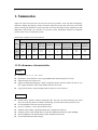
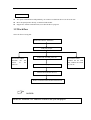
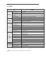
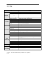
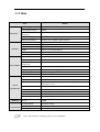
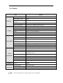
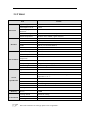
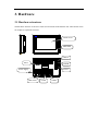
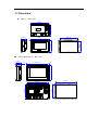
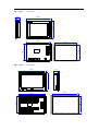
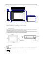
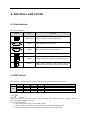
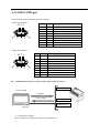
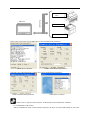
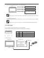
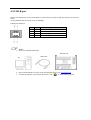
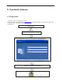
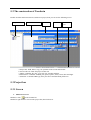
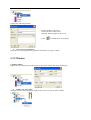
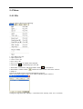
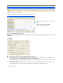
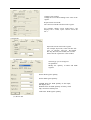
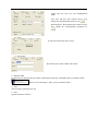
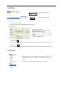
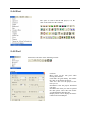
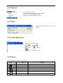
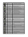
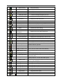
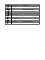
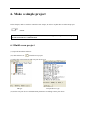
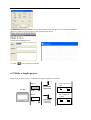
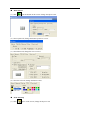
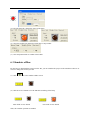
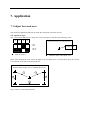
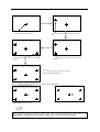
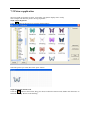
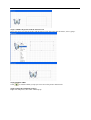
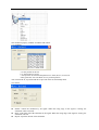
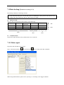
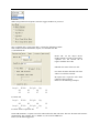
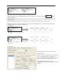
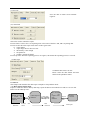
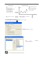
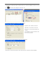
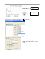
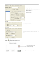
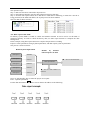
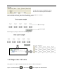
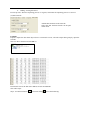
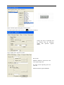
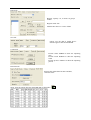
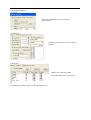
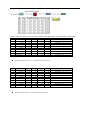
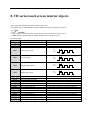
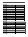
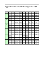
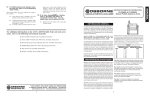
TH series HMI User’s manual Xinje Electronic Co., Ltd. Preface Thank you for buying TH series touch screen made by Xinje Electronic Co., Ltd, this manual should be read and understood before doing relative operation. Purpose This manual will guide readers in the correct operating and maintaining TH series touch screen. Also, this manual refers to the application situations, operations, transportation, storage, set up, installation, maintaining and so on. This manual mainly contains three parts: hardware, software, application. Hardware Part: contain the characteristics, specifications, dimensions, installations and communication connecting of TH series. Software Part: introduce how to use the edit software. Application Part: illustrate the examples; make users to know TH better. Personnel This manual is fit for following personnel: 下面的内容只针对 TP 系列产品。 End Users Please read this manual very carefully before operation and please do the correct operations whileEngineers paying close attention to all the safty points.The following contents only used for TP Technicians series touch screen. Please read the safety notes carefully before using the products. Contact us If you have any questions, please contact us use the following methods: Tel: 86 510 85129136-221 Fax: 86 510 85111290 Address: 4th Floor, Building 7, Original Industrial Park, No.100 Dicui Road, Wuxi, Jiangsu province, China Safety caution Please read the manual carefully before using. Make sure your operation is correct and safety. The following contents are only aimed at TH series products. Please keep the manual properly, put in the location easy to get and read, hand the manual to the end users. NOTICE Please do not bundle power line with communication cable or let them too close, keep at least 10cm. Please do not install module or change the wire. Otherwise it may cause malfunction, error action, damage or fire. Please shut off the power when there is abnormal smell or voice in TH products. (The short sound made by buzzer after power on is normal) Do not strike the touch panel with a hard or sharp object, or press on the touch panel with too much force or with pen, screw, since it may damage the touch panel and cause damage. Please tighten the screws when install the products to prevent from falling off. Please transport, store, set up, install and maintain the products correctly, otherwise the touch panel may be damaged. DANGERS Confirm the rated voltage of TH and connect correct before power on. Please do not touch the terminals after power on to avoid electric shock. Please do not open the cover board. Please cut off all the power when installing or disassembling the products, or it may cause error action and malfunction. Please use TH touch screen in suitable environment conditions according to instructions, otherwise it may cause accident. Please do not use the products where there is high frequency radiate, high magnetic field or other interferences. Catalog Preface............................................................................................................................................... 3 Safety caution.................................................................................................................................... 4 1. Summarize .................................................................................................................................... 7 1.1 Performance characteristics ................................................................................................ 7 1.2 Work flow............................................................................................................................ 8 2. General specification..................................................................................................................... 9 2.1 TH465 ............................................................................................................................... 10 2.2 TH765 ............................................................................................................................... 11 2.3 TH865 ............................................................................................................................... 12 2.4 THA62 .............................................................................................................................. 13 2.5 THA65 .............................................................................................................................. 14 3. Hardware ..................................................................................................................................... 15 3.1 Hardware structure ............................................................................................................ 15 3.2 Dimension ......................................................................................................................... 16 3.3 Installation and using environment ................................................................................... 18 4. Interface and switch ...................................................................................................................... 1 4.1 Introduction ......................................................................................................................... 1 4.2 DIP switch ........................................................................................................................... 1 4.3 COM1/COM2 port .............................................................................................................. 2 4.4 USB-A port ......................................................................................................................... 4 4.5 USB-B port ......................................................................................................................... 5 5. Touchwin software ........................................................................................................................ 6 5.1 Preparation .......................................................................................................................... 6 5.2 The construction of Touchwin............................................................................................. 7 5.3 Project bar ........................................................................................................................... 7 5.3.1 Screen ....................................................................................................................... 7 5.3.2 Window .................................................................................................................... 8 5.4 Menu ................................................................................................................................... 9 5.4.1 File ........................................................................................................................... 9 5.4.2 Edit ......................................................................................................................... 13 5.4.3 View ....................................................................................................................... 13 5.4.4 Part ......................................................................................................................... 14 5.4.5 Tool ........................................................................................................................ 14 5.4.6 Window .................................................................................................................. 15 5.4.7 Help ........................................................................................................................ 15 5.5 Screen editing area ............................................................................................................ 15 5.6 Tool bar ............................................................................................................................. 15 6. Make a simple project ................................................................................................................. 19 6.1 Build a new project ........................................................................................................... 19 6.2 Make a simple project ....................................................................................................... 20 6.3 Simulate offline ................................................................................................................. 22 6.4 Simulate online ................................................................................................................. 23 6.5 Download the project ........................................................................................................ 24 7. Application .................................................................................................................................. 25 7.1 Adjust the touch area ......................................................................................................... 25 7.2 Picture application............................................................................................................. 27 7.3 Debug download ............................................................................................................... 30 7.4 Data backup (Touchwin version≥2.C.3) .......................................................................... 31 7.4.1 Data export ............................................................................................................. 31 7.4.2 Import the CSV data ............................................................................................... 41 8. TH series touch screen interior objects ....................................................................................... 49 Appendix 1 TH series HMI configuration table .............................................................................. 52 1. Summarize Xinje new touch screen TH series are based on TP series products. It not only has the language, characters editing, data display, monitor and alarm functions but also has 65536 true color LCD which can bring you brand-new vision enjoyment. It has the advantage of large capability for data duplication and friendly user interface. It provides perfect humanized solution for industrial system, make it easy to control the system. The function compare between TP and TH: Function compare Series Colors Font setting 3D picture library Adjust the touch area Two ports Animation Password communication independently USB data USB data download duplication TP 256 √ 〇 〇 √ √ √ 〇 〇 TH 65536 √ √ √ √ √ √ √ √ 1.1 Performance characteristics Display LCD size: 4.7”, 7”, 8”, 10.1”, 10.4”. Rich colors: 65536 TFT true color, support BMP, JPG format, display more lively. Adjust function for touch screen. Support multinational language: Chinese, English, Japanese, Korean. Define the font as you like, support underline, italic, bold, shadow and other art words. Large picture library, with preloading mode, no delay for screen motion. Control Switch control, dynamic monitor and display data, bar map, real time trend map, time trend map, XY trend map, discrete/continue column map, real time alarm, history alarm record… User-defined data collection and saving function Set user’s authority, 9 levels password protection Simulate online/offline, upload/download data, configuration function USB port inside, connect flash disk to realize data duplication function, speed 480Mbps Special USB-B port for data download, make the data transfer faster User-defined animation track design Communication Two ports communication independently, can connect two different devices at the same time Drive the panel printer directly, economical and flexible Support free format communication, user edits the driver program 1.2 Work flow The work flow of using TH: Install edit software TouchWin Edit your project Connect PC and TH, power on Do simulate offline Simulate the TH action in the software. Download project in TH Connect TH with other devices Realize communication and data transmission NOTICE: Please use Touchwin V2.C and later version to edit your TH project. Do simulate online Connect the PC with TH, simulate the action in your PC 2. General specification This chapter will introduce the specification of TH series touch screen. TH series touch screen contains TH465, TH765, TH865, THA62 and THA65. Series Type TH465 TH765-M TH765-N TH865 THA65 THA62 TH465-MT TH765-MT TH765-NT TH865-MT THA65-MT THA62-MT TH465-UT TH765-UT TH765-NU TH865-UT THA65-UT THA62-UT TH465-ET TH765-ET TH765-NE TH865-ET THA65-ET THA62-ET 2.1 TH465 Item Electrical Interface Environment Screen specification Memory Construction TH465 Input voltage Consumption current Momentary power off allowance DC20-DC28V 130mA Less than 10ms Withstand voltage Insulated impedance AC1000V-10mA 1 minute ( signal and time ) DC500V- about 10MΩ ( signal and time ) COM2 Support RS-232/RS422/RS485 USB1 USB2 USB-A ( accord with USB2.0 ) USB-B ( accord with USB2.0 ) Ethernet port RJ-45 Environment temperature Operation temperature 20-85% ( no condensation ) Reserve temperature Withstand oscillation Anti-jamming -20-60℃ 10-25Hz ( X, Y, Z each direction 30 minutes 2G ) Voltage noise: 1000Vp-p, pulse 1us, 1 minute Surrounding air Protection construction No corrosive gas IP65 Use life More than 50000 hours, 24 hours running when surrounding temperature is 25 ℃ Type 65536 true colors Screen size Resolution Contrast Character Character size Touch panel 4.3 inch 480*272 Non-adjustable Chinese, English, Korean, Japanese… Any size and font 4-wire resistance mode Screen 8MB Mounting dimension Exterior dimension Cooling method 144.0*94.0mm 152.0*102.0*41.8mm Natural air cooling 0-50℃ Notes: The interfaces of each type please refer to appendix 1. 2.2 TH765 Item Electrical Interface Environment Screen specification Memory Construction TH765 Input voltage DC20-DC28V Consumption current 250mA Momentary power off allowance Withstand voltage Less than 10ms Insulated impedance DC500V- about 10MΩ ( signal and time ) COM1 Support RS-232/RS-485 COM2 USB1 Support RS-232/RS422/RS485 USB-A ( accord with USB2.0 ) USB2 Ethernet port USB-B ( accord with USB2.0 ) RJ-45 Operation temperature Reserve temperature 0-50℃ -20-60℃ Environment temperature Withstand oscillation 20-85% ( no condensation ) Anti-jamming Surrounding air Protection construction Voltage noise: 1000Vp-p, pulse 1us, 1 minute No corrosive gas IP65 Type Screen size 65536 true colors 7 inch Use life Resolution Contrast Character Character size Touch panel More than 50000 hours, 24 hours running when surrounding temperature is 25 ℃ 800*480 Non-adjustable Chinese, English, Korean, Japanese… Any size and font 4-wire resistance mode Screen 128MB Cooling method Exterior dimension Mounting dimension Natural air cooling 204.0*150.5*43.9mm 192.0*138.5mm AC1000V-10mA 1 minute ( signal and time ) 10-25Hz ( X, Y, Z each direction 30 minutes 2G ) Notes: The interfaces of each type please refer to appendix 1. 2.3 TH865 Item Electrical Interface Environment Screen specification Memory Construction TH865 Input voltage DC20-DC28V Consumption current 260mA Momentary power off allowance Withstand voltage Less than 10ms Insulated impedance DC500V- about 10MΩ ( signal and time ) COM1 Support RS-232/RS-485 COM2 USB1 Support RS-232/RS422/RS485 USB-A ( accord with USB2.0 ) USB2 USB3 USB-A ( accord with USB2.0 ) USB-B ( accord with USB2.0 ) Ethernet port Operation temperature RJ-45 0-50℃ Reserve temperature -20-60℃ Environment temperature 20-85% ( no condensation ) Withstand oscillation Anti-jamming Surrounding air 10-25Hz ( X, Y, Z each direction 30 minutes 2G ) Voltage noise: 1000Vp-p, pulse 1us, 1 minute No corrosive gas Protection construction Type IP65 65536 true colors Screen size Use life Resolution Contrast Character Character size Touch panel 8 inch More than 50000 hours, 24 hours running when surrounding temperature is 25 ℃ 800*600 Non-adjustable Chinese, English, Korean, Japanese… Any size and font 4-wire resistance mode Screen 128MB Cooling method Exterior dimension Mounting dimension Natural air cooling 224.4*170.8*45.5mm 211.4*157.8mm AC1000V-10mA 1 minute ( signal and time ) Notes: The interfaces of each type please refer to appendix 1. 2.4 THA62 Item Electrical Interface Environment Screen specification Memory Construction THA62 Input voltage DC20-DC28V Consumption current 230mA Momentary power off allowance Withstand voltage Less than 10ms Insulated impedance DC500V- about 10MΩ ( signal and time ) COM1 Support RS-232/RS-485 COM2 USB1 Support RS-232/RS422/RS485 USB-A ( accord with USB2.0 ) USB2 USB3 USB-A ( accord with USB2.0 ) USB-B ( accord with USB2.0 ) Ethernet port Operation temperature RJ-45 0-50℃ Reserve temperature -20-60℃ Environment temperature 20-85% ( no condensation ) Withstand oscillation Anti-jamming Surrounding air 10-25Hz ( X, Y, Z each direction 30 minutes 2G ) Voltage noise: 1000Vp-p, pulse 1us, 1 minute No corrosive gas Protection construction Type IP65 65536 true colors Screen size Use life Resolution Contrast Character Character size Touch panel 10.1 inch More than 50000 hours, 24 hours running when surrounding temperature is 25 ℃ 800*480 Non-adjustable Chinese, English, Korean, Japanese… Any size and font 4-wire resistance mode Screen 128MB Cooling method Exterior dimension Mounting dimension Natural air cooling 272.2*191.7*51.2mm 260.2*179.7mm AC1000V-10mA 1 minute ( signal and time ) Notes: The interfaces of each type please refer to appendix 1. 2.5 THA65 Item Electrical Interface Environment Screen specification Memory Construction THA65 Input voltage DC20-DC28V Consumption current 630mA Momentary power off allowance Withstand voltage Less than 10ms Insulated impedance DC500V- about 10MΩ ( signal and time ) COM1 Support RS-232/RS-485 COM2 USB1 Support RS-232/RS422/RS485 USB-A ( accord with USB2.0 ) USB2 USB3 USB-A ( accord with USB2.0 ) USB-B ( accord with USB2.0 ) Ethernet port Operation temperature RJ-45 0-50℃ Reserve temperature -20-60℃ Environment temperature 20-85% ( no condensation ) Withstand oscillation Anti-jamming Surrounding air 10-25Hz ( X, Y, Z each direction 30 minutes 2G ) Voltage noise: 1000Vp-p, pulse 1us, 1 minute No corrosive gas Protection construction Type IP65 65536 true colors Screen size Use life Resolution Contrast Character Character size Touch panel 10.4 inch More than 50000 hours, 24 hours running when surrounding temperature is 25 ℃ 800*600 Non-adjustable Chinese, English, Korean, Japanese… Any size and font 4-wire resistance mode Screen 128MB Cooling method Exterior dimension Mounting dimension Natural air cooling 311.0*234.0*48.0mm 302.0*225.0mm AC1000V-10mA 1 minute ( signal and time ) Notes: The interfaces of each type please refer to appendix 1. 3. Hardware 3.1 Hardware structure The hardware structure of TH series touch screen includes front and back side. Take TH765-ET as an example to explain the structure. Touch screen PWR LED USB-A Label USB-B THINGET Xinje Electronic Co.,Ltd Power supply RJ-45 24V 0V FG 1 2 34 COM1 COM2 1 2 3 4 DIP switch COM1 COM2 3.2 Dimension TH465 (unit: mm) 92.0 142.0 24V 0V FG 1 2 3 4 PLC 41.8 1 2 3 4 144.0 TH765-M/TH765-N (unit: mm) 7.0 150.5 204.0 192.0 190.0 THINGET 138.5 43.9 136.5 94.0 102.0 152.0 MODE: TW760T S/ N: N20081028028 Xinje Electronic Co.,Ltd 24V 0V FG 1234 1 2 3 4 COM1 COM2 TH865 (unit: mm) 45.5 38.0 170.8 224.4 209.4 157.8 155.8 211.4 1234 24V 0V FG 1 2 3 4 Download THA62 PLC (unit: mm) 272.2 191.7 51.2 260.2 179.7 177.7 258.2 24V 0V FG 1 2 3 4 Download PLC THA65 (unit: mm) 1 23 4 48.0 43.1 +24V 0V FG 302.0 225.0 234.0 223.0 300.0 311.0 3.3 Installation and using environment 1. Install requirements: TH has four ferric mounting racks when out of factory, there are two square holes on the up, down side of TH, use mounting rack to fix the TH with control cabinet. In order to avoid TH temperature too high after long time working, please keep 10cm space on the up/down and 5cm on the left/right side of the TH when installing. Install panel 2. Fixed bracket Install steps Step1 Refer to the dimension in the former chapter to open a rectangle mounting hole in the control cabinet Step2 Add airproof circles in the airproof slot when installing Step3 Insert the bottom of TH into the mounting hole of control cabinet Step4 Insert the install rack into the fix hole of TH then tighten the screw Step5 Connect TH and PLC with communication cable NOTICE: The communication cable can be offered by the supplier or made by user according to the connection diagram, input +24V DC power to start working 3. Environment Please use TH series touch screen indoor. Do not use TH in below environment: Inflammable gas, steam, dust, fast vary temperature, high humidity (it may cause moisture inside TH). 4. Power supply requirements: TH series touch screen use DC +24V power supply only. The permitted voltage range is 20V~28V. The connection is as below: +24V 0 V +DCBesides, if connect high voltage or AC power supply with TH, the TH may be damaged and cause electric shock to human body. NOTE: if use the DC +24V output of PLC to drive the TH, make sure the PLC has enough current to drive the TH. 5. Maintenance and cleaning Maintenance Caution Please do not open the back cover by yourself. Please do not analyze or change TH by yourself Please cut off all the power supply while observing the TH. Please do not touch terminals after power on, otherwise it may cause electric shock. Do not hot plug the cable or pull the cable when communicating, it may destroy the cable. Please periodic check installation and screws to avoid falling off. Please use TH series touch screen in the certain conditions according to instructions. Keep the cleanness of touch area, in order to keep touch sensitivity. Clean Caution Please use clean cloths with little detergent or alcohol to clean the screen. Neutral detergent, without acid, alkali is recommended. Keep the TH away from thrill or strong corrosive gas Never use spray detergent. Avoid damage to the screen, please do not touch the screen too hard while wiping. Disposal Caution ● Please dispose the TH as industry waste. 4. Interface and switch 4.1 Introduction TH series HMI ports: Outline Name Function 1 2 3 4 DIP switch Force-download, touch area adjustment 1 2 3 4 COM1 RS232/RS485 communication COM2 RS232/RS485/RS422 communication USB-A Connect to U disk USB-B Connect USB cable to download/upload program RJ-45 HMI remote assistance, make network between HMI and controller, data exchange between HMIs Download PLC 4.2 DIP switch TH series has 4-bit DIP switch at the back side; they can set the function of COM1 port. Switch State Switch1 ON OFF OFF OFF Switch2 OFF ON OFF OFF Switch3 OFF OFF ON OFF Switch4 OFF OFF OFF ON Function Undefined Force-download mode of USB-B port Adjust mode of touch area Interior check mode ( not recommended to users) Notes: Force-download: if the screen cannot show normally after downloading the program, please use force-download to update the system. Force-download method: (1) Cut off the power of TH, turn ON DIP switch 2. (2) Power on TH, connect the download cable to PC to download the program. (3) Turn OFF DIP switch 2 after finishing the download, repower on the TH. 4.3 COM1/COM2 port TH series HMI COM1/COM2 port has these functions: COM1 pins definition Pin 1 2 3 4 5 6 7 8 9 9 87 6 5 4 3 2 1 Name NC RXD TXD A GND NC B NC NC Meaning Unused terminal RS232 receive RS232 send RS485 + signal Signal ground Unused terminal RS485 – signal Unused terminal Unused terminal COM2 pins definition: 9 87 6 5 4 3 2 1 pins 1 2 3 4 5 6 7 8 9 Name TD+ RXD TXD A GND TDB RDDRDD+ Meaning RS422 send + RS232 receive RS232 send RS485 + Signal ground RS422 send RS485 RS422 receive RS422 receive + Communication function: connect to PLC, printer, inverter, meter… PLC TH series HMI Send data Receive data Inverter Other devices Com port (1) Communicate with PLC TH series HMI can communicate with most of popular PLCs SIEMENS PLC COM port Data transfer TH series Panasonic PLC Other PLCs… Please select correct PLC port (COM2) device and communication parameters: COM2 device selection COM2 communication parameters Select the correct download port (COM1) device and communication parameters: COM1 communication parameters COM1 device selection Please refer to “TP series basic manual” for the details of TH communicate with PLC. (2) Communicate with inverter TH can communicate with various brands of frequency inverters. For the brands which are not in the list, user can select Modbus protocol or user-defined protocol. TH Mitsubishi FR series inverter Inovance MD series inverter Bosch Rexroth Indracontrol L40 COM port Please refer to “TP series basic manual” for the details of TH communicating with frequency inverter. (3) Communicate with meters About the communication between TH and meters, users can select user-defined protocol or Modbus protocol. Please refer to “TP series basic manual” for the details of TH communicating with meters. 4.4 USB-A port TH series USB-A port has below functions: (accord with USB2.0) Realize backup management, data export/import, the speed can up to 480 Mbps. USB-A port definition Pins 1 2 3 4 Name +5V DATA+ DATA-5V Meaning +5V voltage signal Data signal + Data signal -5V voltage signal Connect to U-disk TH front side TH back side USB-A port USB-A 4.5 USB-B port TH has one USB-B port (accord with USB2.0), located at the back side of TH, the functions are shown as below: To download the data, the speed can up to 480Mbps. USB-B port definition: Pins 1 2 3 4 Name +5V DATADATA+ GND Meaning +5V voltage signal Data signal Data signal + Ground signal Notes: 1. Please use shielded USB cables. TH back side USB cable PC 2. Please install USB driver before using. Download the driver from www.xinje.com . 3. Connect TH with PC, open Touchwin software, click to download the program. 5. Touchwin software 5.1 Preparation 1. Software version: V2.C and later versions. 2. Software source: visit Xinje website www.xinje.com to obtain the software or get from the products CD. 3. OS requirements: Windows98/2000/XP/ME/7 4. Install steps: Open setup.exe Click “next” until show below window Enter the information in the space: serial number is ThingetTouchWin. Click “next” to finish your installation. click to use the software. 5.2 The construction of Touchwin Double click the Touchwin software, build a new project, then you can see the following screen: Project bar Screen edit area Menu Tool bar Status bar a. Project bar: build, delete, copy, cut operation of the screen and window b. Screen edit area: make the project in this area c. Menu: it includes file, edit, view, tool, part, window and help. d. Element bar: it includes standard, part, panel, operate, status, zoom, draw and align. e. Status bar: it includes HMI type, PLC port device and download port device. 5.3 Project bar 5.3.1 Screen 1. build a new screen Method 1: click in the element bar. Method 2: right click the screen in the project bar, then click insert. It shows the following window: ID: the number of the screen Name: the name of the screen Message: the description of the screen Click to modify the screen property. 2. screen cut, copy and delete Select the screen in the project bar, right click and choose cut, copy or delete. 5.3.2 Window 1. build a window Right click the window/insert in the project bar. Input the window ID, name and message. 2. window cut, copy, delete Select the window in the project bar, right click to select cut, copy or delete window. 5.4 Menu 5.4.1 File The file menu is shown as the following: 1. New: Build a new file 2. Open: Open a file 3. Close: Close a file 4. Save: Save a file 5. Save as: Save a file as another name and path 6. Download: to download project into TH 7. Run-online: connect PLC and TH, Simulate online in TH software. 8. Run-offline: simulate offline , simulate the touch screen action in the software. 9. PFW set: Initialize the PFW registers when downloading the program. Step1: set the PFW register range, click “Add” to add the register in the list. Change the range then click “Modify”, it will show below message, click ‘Yes” to confirm. Step2: set the value in the range Double click the PFW range, it will show data setting window: Display number can select decimal or hex. Set FF: set all the data to FFFF. Reset 0: set all the data to 0. Step3: download the project into TH. Please note PFW0~PFW256 are occupied by the TH system, please select register start from PFW257. 10. Setting: (1) Para tab: Screen: select the start screen number when TH is power on. Password: there are 9 levels passwords; the level 9 password has the highest priority. The higher level password can be used to all the elements of lower level password. The password is used to protect the element or screen, when input the correct password, the button or screen can be used. Screen save: to protect the LCD. After certain time, the background light will be off or jump to certain screen. Please note “close LCD” and “show screen” only can be selected one of them. (2) Alternation tab: Change screen control: Change the screen ID according to the value of the register. Report current screen ID: The current screen ID will show in the register. For example, change screen control D0=1, TH displays No.1 screen, report current screen ID D1=1. (3)Clock tab: Export the current time to the register. For example, object D0, so the real time will save in D0~D5. D0=year, D1=month, D2=day, D3=hour, D4=minute, D5=second. Please note the export time is hex number. (4) Panel tab: The TH type you are using now. Set parameter: Modify the quantity of PFW and PSW registers. Set the PFW register quantity Set the PSB register quantity VisPSW Num: the PSW quantity in data input, data display area. PriPSW Num: the PSW quantity in history trend map, real time trend map area. Cache num: PFW register quantity (5) Device tab: Single, host net, slave net: TH communication mode. PLC port: TH PLC port connects device type, change the communication parameters by Download port: TH download port connects device type, change the communication parameters by (6) Font: Set the font of the letter in the screen. (7) Project tab: Record the project name, author and remark. 11. Build SCADA It realizes the SCADA function in windows. Build the SCADA file, and double click it to simulate online. Please refer to the chapter “make a project/simulate online “. 12. Last The latest files operated by the user. 13. Exit Quit the Touchwin software. 5.4.2 Edit Cut, copy, paste, undo Public unit, private unit 1. cut, copy, paste, undo These operations are used to the elements in the screen. 2. replace Replace register or coil Find what: the object you want to replace Replace with: the new object Object num: the quantity you want to replace Replace in: replace the object in current screen or all the screens. 3. public unit Select one element in the screen, click public unit, this element will be added in all the screens. 4. private unit After select one element as public unit, click private unit to delete this element in other screens. 5.4.3 View Display all the tool bars. Advance and advance2 is gray color. Only when open the advance function of software, these items can be used. All the items with tick are displayed in the software menu. 5.4.4 Part The “part” is used to edit the TH project, it is the same as the tool bar in the software. 5.4.5 Tool Tool menu is the same as the following tool bar. Option: Grid size: Move Grid: set the min pixel when moving the element. Grid radio: the grid density, the smaller the value is, the denser the grid is. Auto save: auto save the project at the time you set. Download: select the project download com port. Download all: when you want to upload the data, please select this item before you download the data into TH. Display mouse cursor: display the mouse connected to TH USB port. 5.4.6 Window New: build a new window Cascade: show all the window in cascade mode. Tile: show all the window in tiled mode. Arrange icon: arrange all the icons again. 5.4.7 Help Show the Touchwin software version and copyright. 5.5 Screen editing area Edit the project in the screen. Zoom in, zoom out the screen: zoom out, zoom in show the grid in the screen. 5.6 Tool bar Tool bars functions are shown as the following: Icon Name Function New Open Save Cut Copy Paste Build a new project Open the file Save the file Cut the element Copy the element Paste the element Undo Undo the operation Help Check the software version information Text Dynamic text Variational text Lamp Input static text Display the text according to the value of register, support 16 texts, set register value as 0~15 Display the text according to the value of register, set register value as user need Display the ON/OFF state of switch Button ON/OFF the bit element Lamp button Combine the function of lamp and button Screen jump Jump to object screen Digital display Alarm display Text display Display the register value Set the upper/lower limit of register value, when exceeding the range, twinkle display Display characters in multi-registers Digital input Input the data in the register Text input Input characters in the register Set data Set data and used in arithmetic Digital keyboard Digital input keyboard ASCII keyboard Character input keyboard User input One input button of keyboard Bar Dynamic map Call window Window button Display the register value in bar picture Display the map according to the register value, support 16 maps, the register value is 0~15 Call window according to the value in the coil or register Control the open, close of the window Download recipe Download the recipe into object device Upload recipe Upload the recipe into TH register Function button Function field Discrete column map Continue column map Line Arc Realize multi-functions with this button Similar to function button, but the trigger condition is different. Display the data in discrete column map Display the data in continue column map Draw lines Draw arc Rectangle Draw rectangle Ellipse Draw ellipse Fold/polygon Draw fold and polygon Polygon block Similar to container Frame Draw 3D rectangle Map Add jpg or bmp format pictures Move animation make the movement animation of object Rotate animation Switch the picture Material library The picture library Date Display the date Clock Display the time Buzzer Control the buzzer by the coil LCD light control Control the background light by the coil Scale Display the value in scale Instrument Display the value in the meter Valve Simulate the state of valve Pipe Pump Simulate the liquid state in the pipe Simulate the pump running Auto wind Simulate the auto wind Motor Simulate the motor running Retort Inverter alarm information Scroll text Real time map Simulate the retort running Display the inverter alarm information Display the text in scroll mode Display the current value in curve History data map Display the current and history value in curve XY curve Display two curve in X, Y direction XY curve Ex Display the value in line, point and line-point. Time trend control Data moving button Alarm list Display real time event Display history event Common grid control Data grid control Sample save Sample export Align left Display value in certain time space Use with event, curve, alarm event, realize flip, confirm and clear operation Show the inverter alarm information in the list Display real time alarm information, when the alarm is free, the event will be deleted automatically Display many alarm information and event happen time Display a group of register in the table Display a group of register in the table, support time information table To collect the object data, no limit for the sample quantity and time, save the data in TH registers Save the data in TH register and export to object device as CSV format file Align left the objects Align center Align center the objects Align right Align right the objects Align top Align top the objects Align middle Align middle the objects Align bottom Align bottom the objects Zoom out Zoom out the screen Zoom percent Zoom percent Zoom in Zoom in the screen Grid Display grid in the screen State change Dynamic picture state selection Public unit Switch button state display Switch dynamic picture state display Use the unit in all the screens Private unit Use the unit in appointed screen New Build a new screen Property Screen name, author, remark… delete Delete the current screen Simulate offline Simulate online Download Simulate the project in the TH Connect PLC and TH, simulate the project in TH online Download the project in the TH Upload Upload the project from TH to PC Debug download Debug download 6. Make a simple project In this chapter, make a switch to control the PLC output, in order to explain how to make TH project. NOTE: Please make sure the TH type and communication device type; it is important for the project download and device communication. 6.1 Build a new project (1) Open the Touchwin software. (2) Click File/New or to build a new project. (3) Select the correct TH type and com port device type TH type com port device type (4) Set the com port device communication parameters according to PLC port device (5) When download port (COM1) is not used as communication port, please select unuse download port. When use COM1 as com port, please select communication device. (6) Finish the building process. (7) Click to save the project in the PC. 6.2 Make a simple project Make a button on the screen, to control the Y0 output of Xinje XC series PLC. Button Set ON TH HMI Y0 Y1 Lamp Button Set OFF PLC COM port PLC output Y0 is ON Lamp PLC output Y0 is OFF Y0 Y1 ● Make button (1) click , put the button on the screen. Change the object to Y0. (2) select operate tab, change the button operate to reverse. (3) select button tab, change the text to reverse (4) select the color tab, change the button colors ● make the lamp (1) click , put it on the screen, change the object to Y0. (2) select the lamp tab, change the aspect of the lamp. (2) select the twinkle tab, change the lamp state to stop twinkle. (3) color and position tab are similar to the button. 6.3 Simulate offline Do not have to download the project into the TH, you can simulate the project in the Touchwin software. It can save debug time and easy to edit. (1) click to enter simulate offline screen. (2) click the reverse button to see the ON/OFF switching of the lamp. Turn off the reverse button Thus, the simulate operation is finished. turn on the reverse button 6.4 Simulate online By connecting the PLC and PC, it can read the data from PLC, simulate the operate of TH in touchwin software. Do not have to download the project into TH, you can control the PLC in your PC. Make sure the connection is correct between PLC and PC, the com port setting is right. NOTE: only Xinje PLC support the simulate online function with TH. (1) connect Xinje PLC with the PC via serial port. (2) click the to enter simulate online. It will show below message: It means the simulate online is not registered, you only can use it for 2 hours. If you want to use it longer, please contact Xinje company to get register number. (3) click ok to enter simulate online screen. Right click the screen to show below menu: Log: log on time and history record About: the version information of autowin Com port: the serial port number of your PC which is connected with PLC. Register: register to get user right. Exit: exit the autowin. If showing the following message, it means the connection between PLC and PC is not good, or the serial port number is wrong. In this example, we use TH PLC port and PC serial com port3, so select PLC port com 3. (4) click the button to see the lamp ON/OFF. Turn off the reverse button turn on the reverse button When click the reverse button, the PLC output Y0 will switch ON/OFF at the same time. 6.5 Download the project 1. Install the USB driver, users can get it on www.xinje.com . 2. Connect TH USB-B port and PC with USB cable, power on the TH, click project. to download the 7. Application 7.1 Adjust the touch area The touch area adjustment function can make the component touch more precise. The adjustment steps: Step 1: turn on the DIP switch 3, then power on the TH again, it will show the following screen: 1 2 3 4 Calibrate the touch panel Repeat as the target moves around the screen ON Adjust cross OFF ● Turn on switch 3 ● Click the center of the adjust cross Step2: After clicking the cross center, the adjust cross will jump to the second position. Keep on click the cross until the cross jump to the last position 5. Calibrate the touch panel Repeat as the target moves around the screen 1 5 2 4 3 Step 3: Please see the detailed motion: Calibrate the touch panel Repeat as the target moves around the screen (1)click the center of the cross Calibrate the touch panel Repeat as the target moves around the screen (2)click the center of the cross on the top left Calibrate the touch panel Repeat as the target moves around the screen Calibrate the touch panel Repeat as the target moves around the screen (4)click the center of the cross on the right bottom (3)click the center of the cross on the left bottom Calibrate the touch panel Repeat as the target moves around the screen (5)click the center of the cross on the top left to finish the adjust process. Step 4: When finished the adjustment, the result is as the following; Calibrate the touch panel Repeat as the target moves around the screen Calibrate the touch panel Repeat as the target moves around the screen Adjustment process is failed. Please do again. Adjustment process is end. If the adjustment process is end, please turn off the power of TH, then turn off the DIP switch 3, then turn on the power again. Now you can use TH normally. 7.2 Picture application TH series LCD are 65536 true colors, it can make your picture display more vividly. This example will make the picture moving in parallel. Step1: select the picture Click button in the tool bar to open the material library: Select the picture you want, then click “open” button Step2: design the motion track Click the button in the tool bar, drag your mouse to draw the motion track, double click the mouse to finish the drawing. Please see the drawing: Step3: combine the picture with the motion track Drag your mouse to select the picture and the motion track, then right click the mouse, select “group”. Step4: Simulate offline Click to simulate offline your project. You can see the picture motion track. Step5: Change the animation property Right click the picture, then select “animal prop”. The animation property includes coordinate and control. (1) Coordinate a. X: the position on X axis b. Y: the position on Y axis c. Escape time: the time that the photo moves from (X1,Y1) to (X2,Y2) d. Key point X,Y: the coordinate of every motion position You can click the X, Y position and the escape time in the list and modify them. (2) Control Enable: control the animation by bit signal. When the rising edge of the signal is coming, the animation will be activated. Reset: control the end of the animation by bit signal. When the rising edge of the signal is coming, the animation will end. Repeat: repeat the motion of the animation. 7.3 Debug download TH series touch screen support debug download function. This function can be used when you are debugging your project in order to save your time. Compared with normal download function, this function has the following advantages: (1) This function only can be used when debugging the project. (2) The data transfer speed is faster than normal download, save time and cost. Click button in the tool bar to debug download the project into your TH. 7.4 Data backup (Touchwin version≥2.C.3) Data backup includes the following contents: (1) Data collection and export, store the data of TH series HMI into U disk, produce CSV data base file. (2) Import CSV data, transfer the data of U disk to TH series HMI. About CSV file: The CSV file is based on Excel, the format is as the following: Temperature Pressure 30 40 50 35 45 55 Hydraulic pressure 40 50 60 Data Date 2009-8-10 2009-8-12 2009-8-14 Date Time 12:10:10 12:10:45 12:10:23 Time To build CSV file Open Excel, input the data as the up format, then save as CSV file. 7.4.1 Data export Export the data from TH to other device. Step1: click function button or function field , select “export CSV data” and add it. When using function button, please select “pressing” or “releasing” as the trigger condition. Title Data When using function field, please select the trigger condition as you need. Step 2: Double click “export CSV data”, it shows the following window: This window includes destination, import, save and date time tab. (1) Destination tab Device ID: set the object device number which you want to export data, “dynamic set” can connect the D register with the device ID. Path/File: the name of the CSV file Fix name: the data collected each time will be saved in the same file. Re-export title: export the title when collect the data each time Please see the following examples. Length Width 20 32 Height 30 41 Qty 40 37 12 13 Fix name file Length Width 20 Length Height 30 Width 32 Qty 40 Height 41 12 Qty 37 13 Fix name and re-export title file Name add automatic: it exports a new file when collect the data each time. The new file name will increase automatically. For example, file 1 is TH001.csv, file 2 will be TH002.csv. Please see the following picture: Add number after name: add the number after the file name. For example, input 001 , the file name is TH001.csv. Dynamic set: set the number in D register. For example, If D0=20, the file name is TH020, D0=23, the file name is TH023. When “add number after name” and “dynamic set” are both selected, “dynamic set” has priority. Named by date: the file name is added the date. When exporting the data several times at the same day, it will add the data title in the file automatically. For example: ● Export the data the first time on 8/18/2009 Length Width 20 Length ● Export the data the second time on 8/18/2009 Height 30 Width 32 Qty 40 Height 41 12 Qty 37 13 (2) Data tab Register capacity: import register quantity Register mode: Loop: use with “real trend map”, “history data map”, “time trend control”, “sample save”… Line: export the data in the registers to CSV file. It is used to the recipe and data arrays. Add, delete, move up, move down: Add the data titles, select the export data format and type. (3) Save tab Save the data in touch screen internal registers. (4) Control tab This tab is used to control the export. Execute status: to show if it is in exporting state via bit state. If the bit is ON, TH is exporting data. Execute result: show the export result state via the register state. 0- export failed 1- export target device does not exist 2- the memory is not enough 3- file path error 4- reading / writing file failed Execute process: show the exporting process via register, 100 means the exporting process is succeed. (5) Date time To add the date in the CSV file. Please select the data format and time format in the pull down menu. EXAMPLE: This chapter will introduce the data export examples in loop and line mode. <A> Data export in loop mode Purpose: collect the data via history data map, export the data to moveable device and save as CSV file. Please see the whole process: PSW300 value increase 10 every 1 second, use function field to realize it. Process: Produce source Collect object is PSW300 data Collect data by history data map Data collection Save the data in the registers start from PSW400 Export the data Produce CSV file Data export Function filed ● Data change every 1 second PSW300=PSW300+10 ● PSW data change process: 1 second:PSW300=0; 2 second: PSW300=10; 3 second:PSW300=20; 4 second:PSW300=30; History data map ● Collect data in loop mode ● Data source: PSW300 ● Save object: registers start from PSW400 Value Time ● Produce CSV format file ● Data export to the registers start from PSW400 Next, we will introduce the each process: (1) produce the data source: PSW300=PSW300+10 every 1 second: Open the Touchwin software, click Select time: 1 second Add the PSW300=PSW300+10 Please see the TP touch screen manual for this content. arithmetic (2) data collect: use history data map to collect the data every 1 second, use PSB300 to control if it is need to collect. Click ,add it in the screen, change the “trend source” tab. Next, change the display tab: page data is 5, control is PSB300. Page data:5, show 5 numbers each screen Total data:10, it can collect 2 screens data Pick period: 1 second, collect the data every 1 second. Control:PSB300, control the ON/OFF of the data collection by PSB300 Change the save tab: save the data in the registers start from PSW400. Add a button, to control the stop and start of the collection process. The button is related to PSB300. PSW300+10 every second PSB300, to control the ON/OFF of data collection (2) Data export Realize the data export function by function button. Click Add it on the screen, set the button as the following: in the tool bar. Double click the “export CSV file” to continue the setting: Device ID: 1, there is one U disk device. Path/File: name the file to SJDC.csv, re-export the title. Data tab Register capacity: 10 Register mode: loop, to correspond to the history trend map Format: decimal Save tab Save the data in PSW400 Date time tab Date time: export the date and time to the .csv file. Now the data export has been done. Via the simulate offline, you can monitor the data change and operate the button. Turn on the button to start the history data map Click the button to export the data into U disk The operation steps: Step 1: make sure the TH is connected to object device. Step 2: click ON/OFF button to start the data collection in history data map Step 3: click the data export button, the U disk device LED starts to flickering, it means the CSV file is being produced, if the LED ends flicker, the export process has been finished. The CSV data is shown as below: <B> Data export in line mode In industry system, HMI is seemed as control and monitor terminal. It can be used to set all kinds of parameters directly. In order to check the history data, use data export function to complete the data management. In this example, using data export function to complete the parameters recording. Purpose: realize parameters setting by data input button, and data export by data export button. The process is shown as below: Realize by data input button Data input 1 PSW500 Data input 2 PSW501 Realize by function button/export CSV data ● Data export button Data input 3 PSW502 Data input 4 PSW503 Data input 5 ● Set the head address to PSW500. PSW504 Next, we will introduce how to make the project in two parts: Part 1: input the parameters Put the data input button PSW500 on the screen, change the address as the following: PSW501 PSW502 PSW503 PSW504 Save in CSV format file About the data input button, please refer to TP series HMI manual. Part 2: about data export button Click function button, then set as the following: Double click the export CSV data to change the parameters: Destination tab: Device ID: 1 is the U disk number Change the file name to SJDX.csv, export the data to this file. Data tab: Each group of parameters includes 5 values, export 1 group parameter each time, so the register capacity is 1. Register mode is line. Add the title, make it correspond to the parameters. Save tab Set the export object to PSW500, make it the same as the data input button address. In this example, it has not referred to date and time, so do not have to set them. The screen has been done, please see the following picture: Data input Data export Run the project, and you will see the following result: Excel file: SJDX.csv 7.4.2 Import the CSV data The purpose is to import the data from the SD card or U disk to TH register. Step1: use function button or function field , select import CSV data function. Step2: double click import CSV data, change the parameters as the following: (1) Source path tab Device ID: the device number of import device Dynamic set: set the device ID in D register. Import control: control the import process by M coil, when M is ON, the import process starts. Path/File: the CSV file name Fix name: the import data are from the same source file Add ID after name: set the import file name by the input value or the value in D register. Start ID: the import data head number. Dynamic set: can set the head address in D register. Please see the following picture: the import data when select start ID to 5 and 10. When start ID is 5, import these data. When start ID is 10, import these data. When the start ID is 0 or 1, the import data is the first group. (2) Data tab Register capacity: the import data group quantity Register mode: Loop: the data will be stored in the object registers in loop mode, so the original data will be covered. Line: the data import to the object register one after another. Add, delete, move up, move down, title….: Add the data title in the list, and select the data format, type, bit length,etc. Please note the title list items must be the same as the CSV file items. There are 4 items in the title list. There are four items in the CSV file. (3) Save tab The import registers address. (4) Control tab Execute status: to show if it is in importing state via bit state. If the bit is ON, TH is importing data. Execute result: show the import result state via the register state. 0import failed 1- import target device does not exist 2- the memory is not enough 3- file path error 4- reading / writing file failed Execute process: show the importing process via register, 100 means the importing process is succeed. (5) Date time tab Add the date and time in the CSV file. Select the date and time format via the pull down menu. Example: Purpose: import the data from object device to TH touch screen, select the import data group by input the start ID. The CSV file in the SD card is SJDR.csv. In TH touch screen, the data store address starts from PSW400. The realize steps: Step1: use function button or function field . Set as the following: Step2: build the import data group selection button. Put a data input button on the screen----- , change the parameters: Change the object to PSW500 and be constant with the following import data dynamic appoint address. Step3: double click “import CSV data”. Device ID: 1 Path/File: SJDR.csv, must be the same as the object import file. Fix name means importing from the same file. Start ID: dynamic appoint PSW500. Import tab: Register capacity: 10, it means 10 groups of data Register mode: line Add the title: there are 4 rows of data. Save tab: Object: save the data of mobile device into TH register starts from PSW400. Control tab: Execute status: PSB300 to show the importing state Execute result: PSW256 to show the importing result Execute process: PSW257 to show the importing process Date/time tab: Because the import data has time and date, select this item. Step4: show the import data start from PSW400 in “data table” . Change the parameters: Object tab: The object is PSW400, the same to the data import address. Common tab: Set the all records, page records as the left window. Column tab: Add the text as the left window. Set the date time item to time format. The data table is finished, please see the following screen: Step5: connect the mobile device and TH, click the import data button, monitor the data in “data table”. NO 0 1 2 3 4 5 6 7 8 9 ● Length 40 40 40 45 45 50 55 55 55 60 Width 8 10 15 8 10 10 12 14 20 12 Height 10 10 10 6 8 8 10 10 8 10 Qty 15 18 30 25 20 20 15 30 20 25 Date time 2009-08-10 12:10:10 2009-08-10 13:10:10 2009-08-10 14:10:10 2009-08-10 15:10:10 2009-08-10 16:10:10 2009-08-10 17:10:10 2009-08-10 18:10:10 2009-08-10 19:10:10 2009-08-10 20:10:10 2009-08-10 21:10:10 When the import data No = 0 or 1, the data table is shown as up. NO 0 1 2 3 4 5 6 7 8 9 ● Name Group 1 Group 2 Group 3 Group 4 Group 5 Group 6 Group 7 Group 8 Group 9 Group 10 Name Group 1 Group 2 Group 3 Group 4 Group 5 Group 6 Group 7 Group 8 Group 9 Group 10 Length 60 60 65 65 65 65 70 70 55 60 Width 12 20 10 12 18 20 8 16 20 12 Height 10 8 10 5 15 8 8 10 8 10 Qty 25 35 20 15 15 30 18 18 20 25 When the import data No = 10, the data table is shown as up. Date time 2009-08-10 21:10:10 2009-08-10 22:10:10 2009-08-10 23:10:10 2009-08-10 00:10:10 2009-08-10 10:10:10 2009-08-10 00:10:10 2009-08-10 03:10:10 2009-08-10 04:10:10 2009-08-10 20:10:10 2009-08-10 21:10:10 8. TH series touch screen interior objects This chapter will introduce the interior objects of the TH. The interior objects contain PSB(bit register), PSW(word register), PFW(word register). NOTICE 1. Only when the advanced function is opened, the special interior objects can be used. 2. PSB0~PSB255, PSW0~PSW255, PFW0~PFW255 are occupied by system. Bit register PSB Register Function PSB0 Normally closed coil PSB1 Normally open coil PSB2 Turn on during the first scan period Remark 50m s PSB3 100ms pulse signal ON O FF 50m s 500m s PSB4 1s pulse signal ON OFF 500m s 30s PSB5 1minute pulse signal ON OFF 30 s 1 50 m s PSB6 300ms pulse signal PSB15 PSB16 PSB30 PSB31 PSB39 PSB60 PSB61 PSB62 PSB63 PSB64 PSB65 PSB66 PSB67 PSB68 Communication failure Succeed to scan the screen once First scan after download First scan after power on Turn off the touch screen Level 1 password flag Level 2 password flag Level 3 password flag Level 4 password flag Level 5 password flag Level 6 password flag Level 7 password flag Level 8 password flag Level 9 password flag ON OFF 15 0 m s 0: successful 1: failed (1: password is opened, 0: password is closed ) (1: password is opened, 0: password is closed ) (1: password is opened, 0: password is closed ) (1: password is opened, 0: password is closed ) (1: password is opened, 0: password is closed ) (1: password is opened, 0: password is closed ) (1: password is opened, 0: password is closed ) (1: password is opened, 0: password is closed ) (1: password is opened, 0: password is closed ) Word registers PSW Register Function PSW0 Start screen No. PSW1 Current screen No. PSW20 Screen width PSW21 Screen height PSW26 PSB amounts PSW27 PSW amounts PSW28 PFW amounts PSW30 Year PSW31 Month PSW32 Day PSW33 Hour PSW34 Minute PSW35 Second PSW36 Week PSW40 Recipe index PSW54 The device quantity PSW60 COM1 communicate successful time PSW61 COM1 communicate failure time PSW62 COM1 communicate overtime time PSW63 COM1 communicate data error time PSW64 COM1 device version PSW65 COM1 device type PSW70 COM2 communicate successful time PSW71 COM2 communicate failure time PSW72 COM2 communicate overtime time PSW73 COM2 communicate data error time PSW74 COM2 device version PSW75 COM2 device type Word registers PFW Register PFW1 PFW2 PFW10 PFW11 PFW20 PFW21 PFW22 PFW23 PFW24 PFW25 PFW30 PFW31 PFW32 PFW33 PFW34 PFW35 PFW60 PFW62 PFW64 PFW66 Function The screen No. after power on Background color setting Screen saver start time the screen number of screen saver COM1 baud rate COM1 data bit COM1 stop bit COM1 CRC COM1 station NO. COM2 send delay COM2 baud rate COM2 data bit COM2 stop bit COM2 CRC COM2 station NO. COM2 send delay Level 1 password Level 2 password Level 3 password Level 4 password Remark ( read only ) ( read only ) ( read only ) ( read only ) Occupy PSW28、PSW29 ( read only ) ( Hex) ( read only ) ( Hex) ( read only ) ( Hex) ( read only ) ( Hex) ( read only ) ( Hex) ( read only ) ( Hex) ( read only ) ( Hex) ( read only ) Remark 4800、9600、19200、38400、115200、187500 7、8 0-1 bit, 1-1.5 bits, 2-2 bits 0-None, 1-Odd, 2-Even Unit : ms 4800、9600、19200、38400、115200、187500 7、8 0-1 bit, 1-1.5 bits, 2-2 bits 0-None, 1-Odd, 2-Even Unit: ms PFW60、PFW61 PFW62、PFW63 PFW64、PFW65 PFW66、PFW67 PFW68 PFW70 PFW72 PFW74 PFW76 Level 5 password Level 6 password Level 7 password Level 8 password Level 9 password PFW68、PFW69 PFW70、PFW71 PFW72、PFW73 PFW74、PFW75 PFW76、PFW77 Appendix 1 TH series HMI configuration table Series Type TH465 TH465MT TH465UT TH465ET TH765MT TH765UT TH765ET TH765NT TH765NU TH765NE TH865MT TH865UT TH865ET THA62MT THA62UT THA62ET THA65MT THA65UT THA65ET TH765M TH765N TH865 THA62 THA65 LCD size Resolution Screen capacity COM1 4.3’ 480*272 8MB - 4.3’ 480*272 8MB - 4.3’ 480*272 8MB - 7' 800*480 128MB 7' 800*480 128MB 7' 800*480 128MB 7' 800*480 128MB 7' 800*480 128MB 7' 800*480 128MB 8' 800*600 128MB 8' 800*600 128MB 8' 800*600 128MB 10.1' 800*480 128MB 10.1' 800*480 128MB 10.1' 800*480 128MB 10.4' 800*600 128MB 10.4' 800*600 128MB 10.4' 800*600 128MB 232/48 5 232/48 5 232/48 5 232/48 5 232/48 5 232/48 5 232/48 5 232/48 5 232/48 5 232/48 5 232/48 5 232/48 5 232/48 5 232/48 5 232/48 5 COM2 485/42 2/232 485/42 2/232 485/42 2/232 485/42 2/232 485/42 2/232 485/42 2/232 485/42 2/232 485/42 2/232 485/42 2/232 485/42 2/232 485/42 2/232 485/42 2/232 485/42 2/232 485/42 2/232 485/42 2/232 485/42 2/232 485/42 2/232 485/42 2/232 RJ-45 USB-A Download mode - - USB - One USB One One USB - - USB - One USB One One USB - - USB - One USB One One USB - - USB - Two USB One Two USB - - USB - Two USB One Two USB - - USB - Two USB One Two USB Xinje Electronic Co., Ltd. 4th Floor Building 7,Orignality Industry park, Liyuan Development Zone, Wuxi City, Jiangsu Province 214072 Tel: (510)85134136 Fax: (510)85111290 www.xinje.com