1
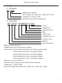
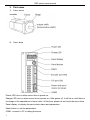
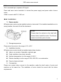
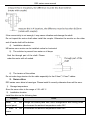
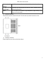
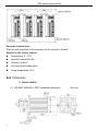
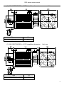
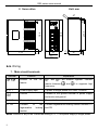
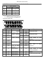
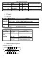
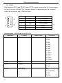
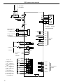
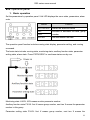
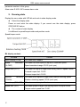
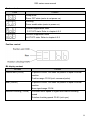
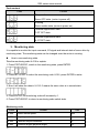
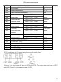
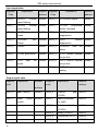
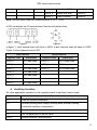
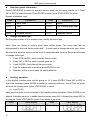
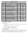
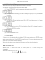
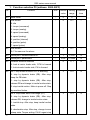
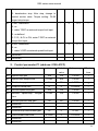
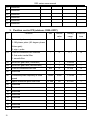
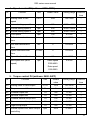
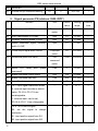
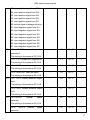
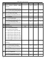
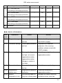
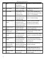
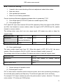
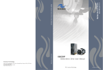
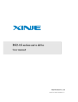
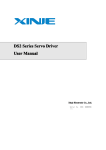
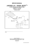
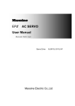
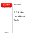
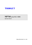
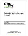
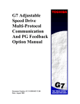
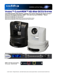
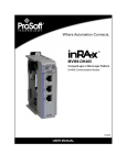
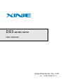
DS3 series servo User manual Xinje Electronic Co., Ltd. No. SC309 20090706 1.0 DS3 series servo manual ►► Safety notes Confirmation after get the products Installation If servo drive is missing parts, broken, type wrong, please do not install it. Cut off all the power before installation. Wiring Cut off all the power before wiring. Connect the AC power to the power terminals on the servo drive. Do not connect output terminal U, V, W of servo drive to 3-phase power. Ground the servo drive with 2mm cables. 2 Running and maintenance Please install the panel guard when power on. Do not touch the terminals within 5 minutes after power off. Do not connect servo drive with loader when test-running. After connect to the loader, please set suitable parameters before running. Do not change the wiring when power on. Do not touch the radiator when running. ►► Product arrival confirmation 1. Confirm the product as the following items. Item The product type is accord with the Remark Please confirm the label of servo drive and motor ordered one Servo motor rotation axis is turning well Can turn by manual. Cannot turn with brake Is the product broken? Please check if there is broken because of transportation Is the screw loose? Motor code Check the screw with screw driver Check the motor code on servo drive and motor, if they are the same If there is inconsistent item, please contact XINJE sales department. 1 DS3 series servo manual 2. Type 1) Servo drive DS3 – 2 1P8 Suitable motor capacity 0P7: 0.75KW, 1P5: 1.5KW, 1P8: 1.8KW, 2P7: 2.7KW Voltage level: 2: 220V, 4: 380V Servo series name: DS3: standard type 2) Servo motor MS -110 ST - M 06030 A Z- 2 1P8 Power Voltage level Power-loss brake Shaft Feature code Feedback part code Sine drive motor Base No. Motor series name Base No.: 60, 80, 110, 130; Feedback part code: M (optical pulse encoder) Feature code: first 3-bit means rated torque; last 2-bit means rated speed 00630: rated torque 0.6N·m, rate speed: 3000rpm 02430: rated torque 2.4N·m, rate speed: 3000rpm 06030: rated torque 6.0N·m, rate speed: 3000rpm 10015: rated torque 10.0N·m, rate speed: 1500rpm Shaft type: A-no key, B-with key Power-loss brake: vacant-no, Z-with DC99V power-loss brake Voltage level: 2-220V, 4-380V Power: 0P2-0.2KW; 0P4-0.4KW; 0P7-0.75KW; 1P5-1.5KW; 1P8-1.8KW 2 DS3 series servo manual 3. Part name 1) Servo motor 2) Servo drive Power LED: turn on when servo drive is power on. Charge LED: turn on when servo drive is power on. After power off, it will be on until there is no charge in the capacitance of servo drive. At this time, please do not touch the servo drive. Panel display: to display the servo state, alarm and parameters. Panel button: to set the parameters. COM1: connect to PC to debug the servo. 3 DS3 series servo manual CN2: connect the encoder. CN1: command input, sequence I/O signal Power and servo motor terminals: to connect the power supply and power cable of servo motor. COM2: connect with PLC, HMI, ect. ►► Installation 1. Servo motor MS series servo motor can be installed vertical or horizontal. If it is installed unsuitable or is in wrong location, the motor life will be shortened. Notes: Please clear the antirust on the shaft with thinner before install the motor. The thinner cannot touch other parts of motor. 1) Storage temperature Please store the motor in the range of -20~+60℃ 2) Installation location MS series servo motor should be installed under below location: Indoor, no corrosive, flammable, explosive gas Good ventilation, less dusts, humidity Ambient temperature is in the range of 0~50 ℃ Relative humidity is in the range of 20%~90% RH, no condensation Easy to clean and check 3) Concentricity Please use coupler when connect to the machine, make the shaft center of motor and machine on the same line. The installation of motor should be accord with the below requirements. 4 DS3 series servo manual If the concentricity is not enough, it may cause vibration and damage the shaft. Do not impact the motor shaft when install the coupler. Otherwise the monitor on the other end of loader shaft will be broken. 4) Installation direction MS series servo motor can be installed vertical or horizontal. 5) The solution to prevent from water or oil drops Seal the through part of the shaft. Please order the motor with oil sealed. 6) The tension of the cables 2 2 Do not make large tension for the cable especially for the 0.2mm , 0.3mm cables. 2. Servo drive DS3 series servo drive is base-type. Please install it correctly otherwise there will be error. 1) Storage temperature Store the servo drive in the range of -20~+85 ℃. 2) Installation location Install the drive as the following item: Location Install in Notes the control panel If close heater 5 to Design the control panel size, servo configuration and cooling mode, to decrease the ambient temperature under 50℃ the to decrease the ambient temperature under 50℃ DS3 series servo manual If close to the Install the shockproof device on the installation side of servo drive to the To prevent the corrosive gas from the servo drive, otherwise there will vibration If close corrosive gas be error for the circuit. Others Do not install in the location of high temperature, high humidity, full of dusty and metal powder. 3) Installation direction The direction must be vertical to the wall. Cool the servo by natural convection or fan. 4) Installation standard Please install the servo drive as the below figure. 6 DS3 series servo manual Direction of servo drive The front side must face to the operator, and be vertical to the wall. Ambient in the control cabinet: Temperature: 0~50 ℃ Humidity: below 90% RH Vibration: 4.9m/s No freeze and condensation Using temperature: 50 ℃ 2 ►► Dimension 1. Servo motor (1) MS-80ST-M02430□□-20P7 installation dimension 7 Unit: mm DS3 series servo manual (2) MS-110ST-M06030□□-21P8 installation dimension Type LA MS-110ST-M06030□□-21P8 219 (3) MS-130ST-M10015□□-21P5 installation dimension Type LA MS-130ST-M10015□□-21P5 213 Unit: mm Unit: mm 8 DS3 series servo manual 2. Servo drive Unit: mm .5 67 4 67 152 177.7 186 53 75 4.2 12 186 12 4.1 R2 ►► Wiring 1. Main circuit terminals Terminal 1, 2 Function connect to Explanation the DC reactor 1 and 2 are shorted together. Connect reactor between 1 and 2 to suppress high harmonics R, S, T Power supply input 3-phase or single phase 200~240V, 50/60Hz Ground Connect to the ground terminal of power supply and motor and ground U, V, W Connect to the motor Connect to the motor P+, PB Connect Connect regenerative braking resistor between P+ regenerative to the braking and PB resistor Notes: connect to any of the 2 terminals among R, S, T if the power supply is single phase. 9 DS3 series servo manual 2. Servo motor winding connector terminals Signal Motor terminal 80 series 110, 130 series PE 4 1 U 1 2 V 3 3 W 2 4 3. CN1 terminal arrangement Look at the solder side: No. Terminal 1 GND 2 CZ 3 Explanation No. Terminal 19 V-REF transistor output 20 GND SO3- Output terminal 21 T-REF 4 SO3+ 3 22 GND 5 SO2- Output terminal 23 PL1 Z phase 2 6 SO2+ 7 SO1- 8 9 Explanation Analog set, speed Analog set, torque Power supply for open collector 24 PULS- Input pulse A (pulse signal) Output terminal 25 PULS+ SO1+ 1 26 SIGN- Input +24V +24V for input 27 SIGN + direction) 28 PL2 pulse B (pulse terminal 10 SI7 Input terminal 7 Power supply for open collector command 11 SI6 Input terminal 6 29 NC Vacant 12 SI5 Input terminal 5 30 ZO+ Z phase differential output 13 SI4 Input terminal 4 31 ZO10 DS3 series servo manual 14 NC Vacant 32 BO+ 15 SI3 Input terminal 3 33 BO- 16 SI2 Input terminal 2 34 AO+ 17 SI1 Input terminal 1 35 AO- 18 GND Ground 36 GND B phase differential output A phase differential output Ground 4. I/O signal (1) Input signal Type Input terminal Function Digital input SI1~SI7 Multi-functional input Pulse input PULS+, PULS- P2-00=1: A phase pulse; P2-00=2: pulse SIGN+, SIGN- P2-00=1: B phase pulse; P2-00=2: direction Analog V-REF Set speed or limit speed input T-REF Set torque or limit torque (2) Output signal Type Output terminal Function Optical output SO1~SO3 Multi-functional output Transistor CZ, GND Z phase transistor output Differential AO+, AO- A phase differential output output BO+, BO- B phase differential output ZO+, ZO- Z phase differential output output 5. CN2 terminal arrangement Look at the solder side: 11 DS3 series servo manual Drive port Motor encoder port Name Drive Motor encoder port port 80 Name 80 110/130 series series 1 9 4 A+ 2 13 7 A- 3 4 5 B+ 4 14 8 B- 5 7 6 Z+ 6 5 9 Z- 7 2 2 +5V 8 +5V +5V 10 +5V 9 110/130 series series 11 6 10 U+ 12 8 13 U- 13 10 11 V+ 14 12 14 V- 15 11 12 W+ 16 15 15 W- 17 3 3 GND 18 GND GND 20 GND 19 Cover 1 1 SHIELD 6. Communication port (1) COM1 COM1 support RS232 mode, connect with PC to debug the servo. When communicate with PC, set F5-00 to C-OUT mode, the panel operation is invalid. If exits C-OUT, the communication between PC and servo will be invalid. The communication parameter of COM1 cannot be modified: Baud rate: 19200bps, data bit: 8, stop bit: 1, even checking, Modbus station 1. Look at the servo drive side, COM1 pin figure: Pin Name Explanation 4 RXD RS232 receive 5 TXD RS232 send 8 GND RS232 ground 12 DS3 series servo manual (2) COM2 COM2 supports RS232 and RS485, Modbus-RTU protocol. It can realize 1:N communication. It is used to connect with HMI, PLC and other devices. Its parameters can be configured. Look at the servo drive side, COM2 pin figure: Pin Name Explanation 2 RXD RS232 receive 3 TXD RS232 send 5 GND RS232 ground 7 B RS485- 4 A RS485+ The parameters of COM2 can be set in P0-04: Parameter P0-04.0 Function Baud rate Default value 6 Set range 0~9 0: 300 1: 600 2: 1200 3: 2400 4: 4800 5: 9600 6: 19200 7: 38400 8: 57600 9: 115200 P0-04.1 Data bit 0 0: 8 P0-04.2 Stop bit 2 0: 2-bit 2: 1-bit P0-04.3 Checking bit 2 0~2 0: no checking 1: odd 2: even 13 DS3 series servo manual Modbus station No. can be set in P0-03. Parameter P0-03 Function Modbus station No. Unit - Default value 1 Set range 1~255 7. Connection example 14 DS3 series servo manual AC 220V (50/60Hz) 1 2 R S T P+ PB FIL U V M W PE U V W CN2 PG Properly Speed command Speed limit Rated speed ±10 Torque command Torque limit Rated torque ±10 the shield thread V-REF SG 19 20 10Ω 34 A/D T-REF SG 35 21 22 10Ω 32 33 10Ω 30 PULS PULS+ PULS- Position SIGN handle 31 25 2 24 SIGN+ 27 SIGN- 26 command 1 AO+ AOBO+ BOZO+ Encoder Output ZOCZ GND +5V Power for Open PL1 23 150 Ω PL2 28 Collector +24VIN Enable ON ( ON Effective) P action ( ON Effective) Forward suppression ( OFF Effective ) Reverse suppression ( OFF Effective ) Alarm reset ( ON Effective ) Forward torque limit ( ON Effective ) Reverse torque limit ( ON effective ) 15 9 3.3K Ω /S-ON 17 /P-CON 16 8 COIN+ 15 7 6 COINALM+ /N-OT 13 5 /ALM-RST 12 4 ALMS-RDY+ /P-CL 3 /P-OT 11 /N-CL 10 S-RDY- Self-defined Output DS3 series servo manual ►► Operation panel 1. Basic operation Set the parameters by operation panel. 5-bit LED displays the servo state, parameters, alarm code. Button Function STATUS/ESC Switch the state and return INC Increase or decrease the data, group DEC number ENTER Set and monitor the data The operation panel function includes running state display, parameter setting, and running command. The basic state includes running state, monitoring state, auxiliary function state, parameter setting state, alarm state. Press STATUS/ESC to see these states one by one. Monitoring state U-XXX: XXX means monitor parameter number Auxiliary function state FX-XX: first X means group number, next two X means the parameter number in this group Parameter setting state PX-XX: first X means group number, next two X means the 16 DS3 series servo manual parameter number in this group Alarm state E-XXX: XXX means alarm code 2. Running state Display the servo state with LED bit and code in state display mode. Select the display state Power on and enter the state display. If you cannot see the state display, press STATUS/ESC button. The content of state display It is different in speed/torque mode and position mode. Speed/torque mode: Bit display content: Bit data Content Servo enable (S-ON) ON when servo enable Speed ON when the motor speed is equal to command speed. consistent (/V-CMP) Speed consistent range: P5-03 (unit: rpm) Torque limit (/CLT) ON when the torque is larger than setting value in speed control Forward torque limit: P4-02 Reverse torque limit: P4-03 Rotation checking ON when motor speed is larger than rotation checking speed (/TGON) Rotation checking speed: P5-02 (unit: rpm) Zero clamp (/ZCLAMP) ON when zero clamp is effective Speed limit (/VLT) ON when speed is larger than setting value in torque control Torque control speed limit: P4-07 17 DS3 series servo manual Code content Code Content Sleep mode Servo OFF state (motor is not power on) Running Servo enable state (motor is power on) Forward suppression state P-OT OFF state. Refer to chapter 4-2-2 Reverse suppression state N-OT OFF state. Refer to chapter 4-2-2 Position control Bit display content Bit data Position end (/COIN) Content In position control, ON when set position is equal to actual position Position range: P5-00 (unit: command pulse) Near (/NEAR) In position control, ON when set position is equal to actual position Near signal range: P5-04 Rotation checking (/TGON) ON when motor speed is higher than rotation checking speed Rotation checking speed: P5-02 (unit: rpm) 18 DS3 series servo manual Code content Code Content Sleep mode Servo OFF state. (motor is power off) Running Servo enable state. (motor is power on) Forward suppression state P-OT OFF state Reverse suppression state N-OT OFF state 3. Monitoring state It is capable to monitor the input command, I/O signal and internal state of servo drive by monitoring state. The monitoring state can be changed even the motor is running. How to use monitoring state Take the monitoring code U-016 to explain. 1. Press STATUS/ESC, switch to the monitoring state, press ENTER. 2. Press INC or DEC to select the monitoring code U-016, press ENTER to enter. 3. Now it will show the data in U-016. 0 means the servo drive is in normal state. 4. Press ENTER, the monitoring code will increase by 1. 5. Press STATUS/ESC to return to monitoring code switch state. Monitoring code Code Content Unit U-000 Motor actual speed rpm U-001 Input speed command rpm U-002 Internal torque command % U-003 Rotation angle (physical angle) 0.1° 19 DS3 series servo manual U-004 Rotation angle (electricity angle) 0.1° U-005 Bus voltage V U-006 Module temperature 0.1 ℃ U-007 Input command pulse speed rpm U-008 Shift command (0000~FFFF)*1 Command U-009 pulse value (0000~FFFF)*9999 pulse U-010 Rotation angle (0000~FFFF)*1 Encoder U-011 (encoder value) (0000~FFFF)*9999 pulse U-012 Input command (0000~FFFF)*1 Command U-013 pulse quantity (0000~FFFF)*9999 pulse U-014 Feedback (0000~FFFF)*1 Command U-015 command pulse (0000~FFFF)*9999 pulse quantity U-016 Current position (0000~FFFF)*1 Encoder U-017 (accumulative) (0000~FFFF)*9999 pulse U-018 Present current (precision=0.1) 0.1A U-019 Analog input V-REF 0.01V U-020 Analog input T-REF 0.01V U-021 I/O signal state U-022 I/O terminal state U-021 can display the I/O signal state. Next we will explain them. Figure 1 Figure 2 In figure 1, the input state will show in LED4 and LED5. The output state will show in LED1 and LED2. Figure 2 is the segment code of LED. 20 DS3 series servo manual Input signal state Segment Explanation Code LED4_0 /SPD-A internal Modbus Segment Explanation Modbus address Code 0x0808 LED5_0 /S-ON servo signal 0x0800 0x0809 LED5_1 /P-CON 0x0801 address speed setting LED4_1 /SPD-B internal speed setting LED4_2 /C-SEL action command control 0x080A LED5_2 mode LED4_3 /P-OT forward 0x0802 reverse 0x0803 suppression /ZCLAMP zero 0x080B LED5_3 clamp LED4_4 proportional /N-OT suppression Vacant 0x080C LED5_4 /ALM-RST clear the 0x0804 /P-CL forward external 0x0805 alarm LED4_5 /G-SEL gain switch 0x080D LED5_5 torque limit LED4_6 /CLR clear the 0x080E LED5_6 pulse /N-CL reverse external 0x0806 torque limit LED5_7 /SPD-D internal speed 0x0807 setting Output signal state Segment Explanation Modbus code Segment Explanation Modbus code address address LED1_0 Near (/NEAR) 0x081A LED2_0 Position end 0x0812 (/COIN) LED1_1 Alarm output 0x081B LED2_1 (/ALM) Speed consistent 0x0813 (/V-CMP) LED2_2 Rotation checking 0x0814 (/TGON) 21 LED2_3 Ready (/S-RDY) 0x0815 LED2_4 Torque limit (/CLT) 0x0816 LED2_5 Speed 0x0817 limit DS3 series servo manual checking (/VLT) LED2_6 Brake lock (/BK) 0x0818 LED2_7 Warn (/WARN) 0x0819 Note: the state value read from communication: 0=OFF, 1=ON. U-022 can display the I/O terminal state. Next we will explain them. Figure 1 Figure 2 In figure 1, input terminal state will show in LED5, output terminal state will show in LED2. Figure 2 is the segment code of LED. Input terminal Segment code Explanation Output terminal Segment code Explanation LED5_0 SI1 input state LED2_0 SO1 output state LED5_1 SI2 input state LED2_1 SO2 output state LED5_2 SI3 input state LED2_2 SO3 output state LED5_3 SI4 input state LED5_4 SI5 input state LED5_5 SI6 input state LED5_6 SI7 input state 4. Auxiliary function Do some application operation on the operation panel in auxiliary function state. Function code Content F0-** View the system information F1-** Auxiliary running state, display running state, auxiliary running command, auxiliary running result F3-** View the alarm message, clear the alarm message F4-** Set the parameter to default value F5-00 Monitor external communication 22 DS3 series servo manual View the system information Press STATUS/ESC to switch to auxiliary function state, set the group number to 0. Press INC or DEC to select the code. Press ENTER to enter, press STATUS/ESC to return. System information code: Code Explanation Code Explanation F0-00 Motor code F0-01 Series F0-02 Type F0-03 Out of factory date: year F0-04 Out of factory date: month day F0-05 Software version 1 F0-06 Software version 2 F0-07 Hardware version Change the motor type Set the group number to 2 in auxiliary state, modify the motor type. Servo drive can match to motors which have similar power. The motor type can be distinguished by the code on the motor label. If users need to change the motor type, check the manual in advance, make sure the motor is compatible with the drive. Below are the steps of change motor type. 1. Press STATUS/ESC, select auxiliary function state. 2. Press INC or DEC to select function group no. 2. 3. Press ENTER, it will show all the motor code. 4. Find the code match to the drive, press ENTER to exit. 5. Repower on the drive to make the setting effective. Auxiliary operation In the auxiliary function state, set the group no. to 1, press ENTER. Press INC or DEC to select the command, press ENTER to make the command effective. The LED on the panel will show the running state, press STATUS/ESC to return. (1) Jog (F1-00) Make sure the motor is not connected to the machine before operation. Press ENTER to set whether to enable the drive. In enable the drive mode, press INC to forward jog, press DEC to reverse jog. Press STATUS/ESC to exit. Four states in jog mode: State Idle 23 Panel display State Forward jog Panel display DS3 series servo manual Enable Reverse jog (2) Test run (F1-01) Make sure the motor is not connected to the machine before test run. When servo drive connects to non-original encoder or power cables, please enter test run state to ensure the encoder or power cables connect correctly. In test run mode, the panel LED shows 0 and twinkles which means user must modify the voltage (unit: %). The suggested value for voltage is 20. Press ENTER to make the motor power on. The motor will forward run at certain speed. If the motor doesn’t run, increase the voltage until the motor can run stable. If the connection is error, the motor will reverse run or lock at certain angle whatever how big is the voltage. Please cut the power at this time and check the connection carefully. Press STATUS/ESC to exit. (3) Current checking offset auto-adjustment When servo drive finished self-update or the motor run unstable for long time, it needs to run current checking offset auto-adjustment. Select F1-02 to enter this function, the LED displays rEF. Press ENTER, the rEF is twinkling. After about 5s, the current checking offset auto-adjustment ends, the LED displays donE. Press STATUS/ESC to exit. (4) Speed offset auto-adjustment Select F1-03 to enter this function, LED displays rEF_o. Press ENTER, the rEF_o is twinkling. After about 1s, the speed offset auto-adjustment ends, the LED displays donE. Press STATUS/ESC to exit. (5) Torque offset auto-adjustment Select F1-04 to enter this function, the LED displays rEF_o. Press ENTER, rEF_o is twinkling. After about 1s, the torque offset auto-adjustment ends, the LED displays donE. Press STATUS/ESC to exit. (6) Forced function (F1-05) 0: cancel this function 1: forced function enables View the alarm information In auxiliary function state, set the group no. to 3 to enter alarm information. Below is the steps: (1) Press STSTUS/ESC, select auxiliary function state. (2) Press INC or DEC, set the function code to 3. 24 DS3 series servo manual (3) Press ENTER, it will display the latest alarm code. Alarm code Content F3-00 ※1 0x0716 ※2 0x0717 Current alarm code Unit Modbus address F3-01 Current alarm code F3-02 Alarm/warn code 1 when alarming F3-03 U-phase current when alarming A 0x0719 F3-04 V-phase current when alarming A 0x071A F3-05 DC bus-voltage when alarming V 0x071B F3-06 IGBT module temperature when alarming ℃ 0x071C F3-07 The speed when alarming rpm 0x071D F3-08 Internal torque command when alarming % 0x071E F3-09 V-REF value when alarming V 0x071F F3-10 T-REF value when alarming V 0x0720 F3-11 Alarm/warn code 2 when alarming 0x0728 F3-12 Alarm/warn code 3 when alarming 0x0729 F3-13 Alarm/warn code 4 when alarming 0x072A F3-14 Alarm/warn code 5 when alarming 0x072B F3-15 Alarm/warn code 6 when alarming 0x072C F3-16 Alarm/warn code 7 when alarming 0x072D 0x0718 ※1: F3-00=0, means no alarm state. ※2: F3-01=0, means no warn state. Factory reset (1) close the servo enable signal (set OFF the S-ON signal or make the enable ineffective) (2) Press STATUS/ESC to enter auxiliary function state. (3) Press INC or DEC to set the group no. to 4. (4) Select F4-00. Set it to 1, press ENTER to confirm. External monitoring In auxiliary function state, select parameter F5-00, it shows C-OUT (in external monitoring state, serial port 1 is effective, panel monitoring is ineffective). User can debug the servo drive in the PC at this time. Press STATUS/ESC to exit and return to panel monitoring. 25 DS3 series servo manual 5. Parameter setting Select the function by setting the parameters. Below are the steps: For example: change the P3-09 value from 2000 to 3000. (1) Press STATUS/ESC, switch to parameter setting state, press ENTER. (2) The second LED is twinkling, press INC to change the group no. to 3, press ENTER to confirm. (3) The last two LEDs are twinkling, press INC or DEC to set the group no. to 9, press ENTER to confirm. (4) Now it displays the value in P3-09 and twinkling. Press INC to change the value to 3000, press ENTER to confirm. (5) Press STATUS/ESC to exit. 6. Error alarm If there is error, the alarming will auto-display. E-XXX means system error. EEEEE means panel communication error. Press ENTER to reset the error. If the servo alarming causes the power off, it is no need to clear the alarming. Note: when the alarm occurs, please find the reason, and then clear the alarming. ►► Parameter list Effective time: “○” means servo OFF; “●” means power on; “√” means running and changeable. Parameter construction: PX-XX=×× ×× PX-XX. H PX-XX.L 26 DS3 series servo manual 1. Function selection P0 (address: 0000~00FF) P0- Function Unit Default Setting Effective value range time 00 Main mode - 0 0 01 Sub mode 1 - 0 0~7 ○ - 0 0~7 ○ 0: idle 1: torque (command) 2: torque (analog) 3: speed (command) 4: speed (analog) 5: position (internal) 6: position (pulse) 7: speed (pulse) 02 Sub mode 2 0~7 the same as the above 03 Serial port 2 Modbus station no. - 1 1~255 ● 04 Serial port 2 parameters - 2206 0~2209 ● 05 Rotation direction selection - 0 0, 1 ● - 2 0~2 ● - 2 0~3 ● 0: look at motor loader side, CCW is forward 1: look at motor loader side, CW is forward 06 06.L: stop mode for servo OFF or alarming 0: stop by dynamic brake (DB). After stop, keep the DB state. 1: stop by dynamic brake (DB). After stop, release DB and change to inertial motion state. 2: stop inertial motion. Motor is power off. Stop by machine friction. 06.H: stop mode when over-range (OT) 0: stop by dynamic brake (DB). After stop, release DB, change to inertial motion state. 1: inertial stop. After stop, keep inertial motion state. 2: deceleration stop. After stop, change to zero clamp state. Torque setting: P4-06 urgent stop 27 DS3 series servo manual torque. 3: deceleration stop. After stop, change to inertial motion state. Torque setting: P4-06 urgent stop torque. 07 T-REF distribution - 0 0~3 ○ - 0 0, 1 ○ 0: no 1: make T-REF as external torque limit input 2: un-defined 3: P-CL, N-CL is ON, make T-REF as external torque limit input. 08 V-REF distribution 0: no 1: make V-REF as external speed limit input. 09 Reserved 10 Reserved 2. Control parameter P1 (address: 0100~01FF) P1- Function Unit Default Setting range value Effective time 1Hz 100 1~5000 √ 0.1ms 400 1~5000 √ Position-loop gain 1/s 30 1~2000 √ 03 Rotation inertia ratio % 0 0~20000 √ 04 Second speed-loop gain 1Hz 150 1~5000 √ 05 Second 0.1ms 100 1~5000 √ 1/s 80 1~2000 √ 1% 0 0~100 √ 0.01ms 0 0~65535 √ 00 Speed-loop gain 01 Speed-loop integral time 02 speed-loop integral time 06 Second position-loop gain 07 Reserved 08 Reserved 09 Position-loop feed-forward gain 10 Feed-forward filter time 11 Reserved 12 Reserved 28 DS3 series servo manual 13 Reserved 14 Reserved 15 Reserved 16 Reserved 17 Reserved 18 Reserved 3. Position control P2 (address: 0200~02FF) P2- 00 Function Command pulse mode Unit Default Setting Effective value range time - 2 1, 2 ● - 0 0, 1 ● 1: AB-phase pulse (90 degree phase, 4-time gain). 2: sign + pulse 01 Position command filter selection 0: first-order inertial filter. 1: smooth filter. 02 Electronic gear ratio (numerator) - 1 1~65535 ○ 03 Electronic gear ratio (denominator) - 1 1~65535 ○ 04 Position command filter time ms 0 0~100 ● 05 Reserved 06 Command pulse frequency at rated 100Hz 5000 1~10000 ○ 0.1ms 20 0~1000 √ speed 07 Speed command pulse filter time 08 Reserved 09 Reserved 10 Reserved 11 Reserved 12 Reserved 13 Reserved 14 Reserved 15 Reserved 29 DS3 series servo manual 4. Speed control P3 (address:0300~03FF) P3- Function Unit Default value Setting range Effective time 00 Analog value of rate 0.01V 1000 150~3000 ○ speed 01 Internal setting speed 1 rpm 100 -5000~+5000 √ 02 Internal setting speed 2 rpm 200 -5000~+5000 √ 03 Internal setting speed 3 rpm 300 -5000~+5000 √ 04 JOG speed rpm 100 0~1000 √ 05 Soft start acceleration ms 0 0~65535 ○ ms 0 0~65535 ○ 0.01ms 0 0~65535 ○ 0.01ms 20 0~65535 ○ rpm Rated speed 0~5000 ○ Setting range Effective time 06 Soft start deceleration time 07 Speed command filter time 08 Speed feedback filter time 09 Max speed limit (MAX speed) 3000:4000 Rate speed 1500:2000 5. Torque control P4 (address: 0400~04FF) P4- Function Unit Default value time 00 Analog value of rated torque 0.01V 1000 150~3000 ○ 01 Torque command filter time 0.01ms 0 0~65535 ○ 02 Forward torque limit 1% 300 0~300 √ 03 Reverse torque limit 1% 300 0~300 √ 04 Forward external torque limit 1% 100 0~300 √ 05 Reverse external torque limit 1% 100 0~300 √ 06 Urgent stop torque 1% 300 0~300 ○ 07 Internal speed limit when torque rpm 2000 0~5000 ○ controlling 30 DS3 series servo manual 08 Reserved 09 Internal torque command setting 1% 0 -300~300 √ 6. Signal parameter P5 (address: 0500~05FF) P5- 00 Function Unit Positioning width /COIN Command Default Setting Effective value range time 7 0~250 ○ pulse 01 Zero clamp speed /ZCLAMP rpm 10 0~300 ○ 02 Rotation checking speed /TGON rpm 20 1~1000 ○ 03 Speed consistent signal checking rpm 10 1~250 ○ Command 50 0~10000 ○ 1000 0~65535 ○ 1ms 0 0~500 ○ width /V-CMP 04 Close output signal width /NEAR pulse 05 Differential pulse limit value 256 command pulse 06 Servo OFF delay time (brake command) 07 Brake command output speed rpm 100 0~5000 ○ 08 Brake command wait time 1ms 500 10~1000 ○ 09 Input filter time 5ms 0 0~100 √ 10 10.L: input signal distribution mode - 0 0, 1 √ - 01 00~17 √ 0: external input accords to default value, P5-10.H~P5-17.H are unchangeable. 1: external input, can be set, P5-10.H~P5-17.H are changeable. 10.H: /S-ON servo signal 00: set the signal to always ineffective. 01: input positive signal from SI1. 02: input positive signal from SI2. 31 DS3 series servo manual 03: input positive signal from SI3. 04: input positive signal from SI4. 05: input positive signal from SI5. 06: input positive signal from SI6. 07: input positive signal from SI7. 80: set the signal to always effective. 81: input negative signal from SI1. 82: input negative signal from SI2. 83: input negative signal from SI3. 84: input negative signal from SI4. 85: input negative signal from SI5. 86: input negative signal from SI6. 87: input negative signal from SI7. 11 11.L: /P-CON proportion action - 02 00~17 √ - 13 00~17 √ - 14 00~17 √ - 05 00~17 √ - 06 00~17 √ - 07 00~17 √ - 00 00~17 √ - 00 00~17 √ command The setting is the same as P5-10.H 11.H: P-OT forward run suppression The setting is the same as P5-10.H 12 12.L: N-OT reverse run suppression The setting is the same as P5-10.H 12.H: /ALM-RST clear the alarm The setting is the same as P5-10.H 13 13.L: /P-CL forward external torque limit The setting is the same as P5-10.H 13.H: /N-CL reverse external torque limit The setting is the same as P5-10.H 14 14.L:/SPD-D internal speed selection The setting is the same as P5-10.H 14.H: /SPD-A internal speed selection 32 DS3 series servo manual The setting is the same as P5-10.H 15 15.L: /SPD-B internal speed - 00 00~17 √ - 00 00~17 √ - 00 00~17 √ - 00 00~17 √ - 00 00~17 √ 5ms 4 0~100 √ - 01 00~13 √ - 00 00~13 √ - 00 00~13 √ - 03 00~13 √ - 00 00~13 √ - 00 00~13 √ selection The setting is the same as P5-10.H 15.H: /C-SEL control mode selection The setting is the same as P5-10.H 16 16.L: /ZCLAMP zero clamp The setting is the same as P5-10.H 16.H: reserved 17 17.L: /G-SEL gain switch The setting is the same as P5-10.H 17.H: /CLR clear pulse offset The setting is the same as P5-10.H 18 Reserved 19 Input filter time 20 20.L: /COIN positioning end 00: not output to the terminal 01: output positive signal from SO1 02: output positive signal from SO2 03: output positive signal from SO3 81: output negative signal from SO1 82: output negative signal from SO2 83: output negative signal from SO3 20.H: /V-CMP speed consistent checking The setting is the same as P5-20.L 21 21.L: /TGON rotation checking The setting is the same as P5-20.L 21.H: /S-RDY ready The setting is the same as P5-20.L 22 22.L: /CLT torque limit The setting is the same as P5-20.L 22.H: /VLT speed limit checking 33 DS3 series servo manual The setting is the same as P5-20.L 23 23.L: /BK brake lock - 00 00~13 √ - 00 00~13 √ - 00 00~13 √ - 02 00~13 √ The setting is the same as P5-20.L 23.H: /WARN warn The setting is the same as P5-20.L 24 24.L: /NEAR near The setting is the same as P5-20.L 24.H: /ALM alarm The setting is the same as P5-20.L 25 Reserved ►► Alarm information Alarm Explanation Reason Solution code E-001 E-002 Program damage Parameter damage Cannot pass program Re-download the program, contact self-test with XINJE company Cannot pass parameter Re-power on to reset the self-test parameter, if the recurring problems, please contact with XINJE company E-003 Bus over-voltage Power grid voltage is Check the power grid and too high, not connect regenerative resistor regenerative resistor, regenerative resistor damage or resistor is too large E-004 Bus under-voltage Power grid voltage is Check the power grid voltage too low E-005 E-006 Regenerative Regenerative resistor is Check the connection of resistor error ineffective regenerative resistor Module Run with big loader for decrease the loader, check the temperature is too long time, causes power ventilation device, servo fan, 34 DS3 series servo manual high module temperature too decrease the ambient temperature high, ambient temperature too high E-007 E-008 E-009 Over current Over speed Analog input error Drive U, V, W output Change motor, check motor U, V, short or motor error W connection Motor speed too fast, Check if there is external force motor U, V, W make the motor run too fast, check connection error motor U, V, W connection Input voltage is error Input correct voltage when adjust when adjust zero for zero for 2-channel analog 2-channel analog E-010 Position offset too The difference between Check if the motor is blocked, large setting and actual decrease the setting speed, position is over the limit increase the value of P5-05 when position control E-011 E-012 E-013 E-014 E-015 E-016 Motor U, W, W External short after Check the connection of U, V, W, short power on self-test change damage motor Motor U, V, W Current collection circuit Check the motor wiring, change current error error the servo unit Encoder U, V, W Not connect encoder, Check the encoder wiring, change break encoder wiring error, encoder or reconnect it after power encoder damage off Encoder A, B, Z Not connect encoder, Check the encoder connection, break encoder wiring error, change the encoder or reconnect it encoder damage after power off Speed changes too Encoder wiring error, Add shield layer and check the large (encoder encoder is influenced by encoder connection feedback error) serious interference Over load Over load for long time Change higher power motor or decrease run-time of over load E-017 35 Power off when The power grid cut off Re-power on and wait until the bus running when running voltage is stable DS3 series servo manual ►► Common setting 1. It needs to do current checking offset auto-adjustment under below states: New servo drive After updated the hardware Reset to out of factory parameters Current checking offset auto-adjustment please refers to parameter F1-02. 2. Over range signal (P-OT/N-OT) and servo enable signal (S-ON) (1) Over range signal P-OT and N-OT input from terminal SI3 and SI4 separately. When the signal is ON (SI3/SI4 are 24V), ban forward or reverse rotation; when the signal is OFF (SI3/SI4 are 0V), enable forward or reverse rotation. The settings when users don’t use over range signal: (XX means any value or keep the original value) Parameter code P5-10 Explanation Enable to change P5-11 P5-12 P-OT N-OT 00XX XX00 terminal distribution Setting value (HEX) XX01 (2) Servo enable signal The servo enable signal input from SI1. When the signal is OFF (SI1 is 0V), the servo enables. When the signal is ON (SI1 is 24V), the servo doesn’t enable, power off. The settings when the servo enables (XX means any value or keep the original value) Parameter code P5-10 Explanation S-ON and enable to change terminal distribution Setting value (HEX) 3. 8001 Simple settings of operation mode (1) External pulse control PLC or other motion controller sends continuous pulse, servo drive positioning according to the received pulse quantity and frequency. The electronic gear ratio can be set freely. For example: PLC output continuous pulse, the pulse mode is “pulse + direction”. The servo motor rotates 1.75 circles per 15000 pulses. 36 DS3 series servo manual Wiring: (a) “pulse + direction” signal: “pulse” connects CN1-24/CN1-25, “direction” connects CN1-26/CN1-27. (b) “AB-phase” signal: A-phase connects CN1-24/CN1-25, B-phase connects CN1-26/CN1-27. (c) The shield layer connects to COM terminal of PLC. The details please refer to DS series servo manual Parameters: Calculate the electronic gear ratio: 15000 × gear ratio = 1.75 × pulse quantity per rotation of servo motor Pulse quantity per rotation of servo motor = 2500 × 4 = 10000, so gear ratio = 7/6. Parameter P0-00 P0-01/P0-02 P2-00 P2-02 P2-03 Explanatio Main Sub mode Pulse mode Numerator Denominator n mode of electronic of electronic gear ratio gear ratio 7 6 code Setting 0 6 “AB phase” signal: 1 value “pulse+direction” (HEX) signal: 2 (2) Segment speed control (internal setting speed) For example: SPD-D, SPD-A, SPD-B connects to SI2, SI6, and SI7 separately which are all positive signal input, uses software filter. Three segments of speed are 100rpm, 500 rpm, 1500 rpm, soft start acceleration/deceleration time is 200ms. Wiring: SPD-D connects to CN1-16, SPD-A connects to CN1-11, SPD-B connects to CN1-10, external 24V power supply connects to CN1-9. Terminal parameter setting: Parameter code P5-10 P5-14 P5-15 Explanation Enables to change SPD-A、SPD-D SPD-B 0602 XX07 terminal distribution Setting value (HEX) 37 XX01 DS3 series servo manual Mode parameters: Parameter P0-00 code Explanation Setting value P0-01/ P3-01 P3-02 P3-03 P3-05 P3-06 P0-02 Main Sub Speed Speed Speed Soft mode mode 1 2 3 acceleration deceleration time time 200 200 0 3 100 500 1500 start Soft start (decimal) (3) Mode switch The servo drive can switch to any modes seamlessly. Users only need to set the parameter in single mode: Parameter code P5-10 Explanation Enables P5-15 to change the C-SEL terminal distribution Setting value XX01 00XX At this time, it is ineffective to set P0-02 to sub mode 2. If user wants to switch between two modes, please follow below steps: For example: C-SEL signal inputs from terminal SI2, positive signal, uses software filter. Wiring: C-SEL connects to CN1-16; external 24V power supply connects to CN1-9. Parameters: Parameter code P5-10 Explanation Enables P5-15 to change the C-SEL terminal distribution Setting value XX01 02XX 38 Xinje Electronic Co., Ltd. 4th Floor Building 7,Originality Industry park, Liyuan Development Zone, Province, China 214072 Tel: 86-510-85166657-221 Fax: 86-510-85111290 www.xinje.com Wuxi, Jiangsu