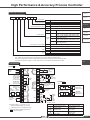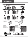
1
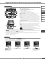
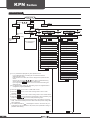
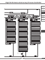
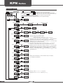
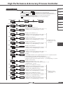
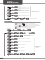
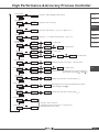
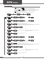
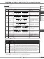
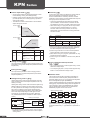
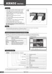
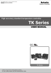
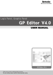
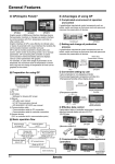
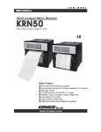
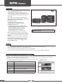
KPN
Series
Features
• Super high-speed sampling cycle
(10 times faster compared to existing models) : 50 ms sampling cycle and ±0.3% display accuracy
• Improved visibility with wide display and high luminance LED
• Easy check control output MV with Bar graph
• High performance control with heating/cooling control
and automatic/manual control modes
• PC parameter setting
(via USB and RS485 communication)
: Integrated device management program (DAQMaster) supported
※ Communication converter, sold separately:
SCM-WF48 (Wi-Fi to RS485, USB converter)
SCM-US48I (USB to RS485 converter),
SCM-38I (RS232C to RS485 converter),
SCM-US (USB to Serial converter),
• Selectable SSR output or current output
Please read “Caution for your safety” in operation manual
before using this unit.
• Heater disconnection alarm (CT input) function
※ CT, sold separately: CSTC-E80LN, CSTC-E200LN
• Multi-SV (up to 4) setting (selectable by digital input
terminal)
• Space saving with compact design: downsized by
38% depth-based (panel rear length: 60 mm)
• Terminal cover, sold separately: R A-COVER
• Multi-input/Multi-range
Manual
• For more information and instructions, refer to the user manual and the user manual for communication. Visit our web site (www.autonics.com) to download the manuals.
• The user manual includes product specifications, functions, and operations.
• The user manual for communication includes information about Modbus RTU protocol, and Modbus mapping table.
Integrated device management program(DAQMaster)
DAQMaster is the integrated device management program to set parameters and manage monitoring data and user group,
parameter mask which are the dedicated function of KPN.
Visit our website (www.autonics.com) to download user manual and integrated device management program.
< Computer specification for using software >
Item
Minimum requirements
System
IBM PC compatible computer with Intel Pentium Ⅲ or above
Operating system Microsoft Windows 98/NT/XP/Vista/7
D-2
Memory
256MB or more
Hard disk
More than 1GB of free hard disk space
VGA
1024×768 or higher resolution display
Others
RS-232 serial port(9-pin), USB port
< DAQMaster screen >
High Performance & Accuracy Process Controller
Ordering information
KPN5
5
0
0
A. Recorder
0
0
0
B. Indicator
Power supply
0
100-240 VAC 50/60 Hz
0
None
3
Transmission output + Remote SV
0
None
2
RS485
1 output
type
0
Option input/output
Option communication output
7
9
The number of control outputs
Size
Item
E. Thyristor
unit
OUT1: Current, SSR drive voltage selection output
OUT2: Current, SSR drive voltage selection output
OUT1: Current, SSR drive voltage selection output
OUT2: Relay output
OUT1: Relay output
OUT2: Current, SSR drive voltage selection output
OUT1: Relay output
OUT2: Relay output
3
2 output
type
D. Controller
Relay, Current, SSR drive voltage selection output
1
Control output※1
C. Converter
0
1 output type (Heating or Cooling type)
1
2 output type (Heating&Cooling type)
2
DIN W96×H48 mm
3
DIN W48×H96 mm
5
DIN W96×H96 mm
KPN5
F. Pressure
transmitter
G. Temp.
transmitter
H. Accessories
Temperature / Process Controller
※1: The 1 output type is heating or cooling output type and the 2 output type is heating & cooling output type.
The 1 output type is able to use only one output among relay, current, SSR drive voltage outputs.
OUT1 of the 2 output type is fixed as heating output and OUT2 of the 2 output type is fixed as cooling output.
If you select the SSR drive voltage or current output model, you can select the appropriate control output.
KPN
Connections
٧٧KPN5 00
AL3 OUT Relay
250VAC 3A 1a
RESISTIVE LOAD
※1
OUT1 Relay
250VAC 5A 1a
RESISTIVE LOAD
Current
SSR
DC0/4-20mA
11VDC±2V
Load 500ΩMax. 20mA Max.
mA
V
2
RS485
Circuit
ADC
3
15
4
16
Control
Circuit
5
6
8
11
12
Remote SV
1-5V
4-20mA
mA
17
Output
Circuit
7
9
V
14
Output
Circuit
ADC
10
SOURCE
100-240VAC,
50/60Hz
13
ADC
mA
19
Current
0.0-50.0A
mA
A
B
mA
V
B'
RTD
Sensor
TC
7
V
Current
SSR
DC0/4-20mA
11VDC±2V
Load 500ΩMax. 20mA Max.
CT Transformer
21
24
※2
Analog Output
DC4-20mA(Trans. output)/
24VDC(LPS)
mA
20
23
Digital
Input
Non-contact,
contact input
٧٧KPN5 1
18
22
Power
Circuit
DI-2
AL1 OUT Relay
250VAC 3A 1a
RESISTIVE LOAD
AL2 OUT Relay
250VAC 3A 1a
RESISTIVE LOAD
1
DI-1
Communication
RS485(A+)
Output
RS485
RS485(B-)
8
9
V
Analog
0-100mV
0-5V
1-5V
0-10V
0-20mA
4-20mA
10
OUT2 Relay
250VAC 5A 1a
RESISTIVE LOAD
OUT1 Relay
250VAC 5A 1a
RESISTIVE LOAD
※2: OUT1, OUT2
※1:Set relay output [ RLY], current [ CUR], or
SSR drive voltage output [ SSR] at OUT1
control output [ OUT1] in parameter 3 group.
Model
※Standard model has shaded terminals only.
is option specification.
KPN5 13
KPN5 11
OUT1 control output
Current, SSR drive voltage
selection output
Current, SSR drive voltage
selection output
KPN5 17
Relay output
KPN5 19
Relay output
OUT2 control output
Current, SSR drive voltage
selection output
Relay output
Current, SSR drive voltage
selection output
Relay output
D-3
KPN
Series
Dimensions
٧٧KPN52
6
Terminal
cover
Min. 115
6
96
64.5
44.8
48
Min. 65
1.5
45 +0.6
0
Bracket
(unit:mm)
● Panel cut-out
92 +0.8
0
٧٧KPN53
6
48
● Panel cut-out
64.5
Min. 65
6
1.5
Min. 115
91.5
96
٧٧KPN55
6
□96
45 +0.6
0
● Panel cut-out
64.5
6
1.5
Bracket
92 +0.8
0
Terminal
cover
Bracket
Min. 115
Min. 115
91.5
٧٧Terminal cover (sold separately)
92+0.8
0
94
● RLA-COVER
(96×96 mm size)
91.5
● RHA-COVER
(48×96 mm size)
92 +0.8
0
Terminal
cover
13
٧٧Current transformer (CT, sold separately)
● CSTC-E80LN
● CSTC-E200LN
Max. load current: 200A (50/60Hz)
※Max. load current for
KPN Series is 50A.
Current ratio: 1/1000
Wire round resistance: 20Ω±10%
Max. load current: 80A (50/60Hz)
※Max. load current for
KPN Series is 50A.
Current ratio: 1/1000
Wire round resistance: 31Ω±10%
A
B
K(Black)
D
L(White)
C
F
D-4
150
(unit:mm)
3
E
Model
A
B
C
D
E
F
CSTC-E80N
Ø23.3
Ø7
26.5
7
3.8
10.5
CSTC-E200N
Ø37.1
Ø13
40.8
10
4.5
13.5
※When using a CT, do not apply primary current when opening CT output.
Or high voltage occurs at CT output.
High Performance & Accuracy Process Controller
Sold Separately
A. Recorder
٧٧Communication converter
SCM-WF48 (available soon)
(Wi-Fi to RS485/USB
communication
converter)
SCM-38
(RS232C to RS485 converter)
SCM-US48
(USB to RS485 converter)
SCM-US
(USB to Serial converter)
B. Indicator
C. Converter
D. Controller
E. Thyristor
unit
F. Pressure
transmitter
Input type and range
G. Temp.
transmitter
Input type
K(CA)
Input range (℉)
-200 to 1350
-328 to 2463
-199.9 to 999.9
TcK2
-199.9 to 999.9
TcJ1
-200 to 800
-328 to 1472
0.1
TcJ2
-199.9 to 800.0
-199.9 to 999.9
1
TcE1
-200 to 800
-328 to 1472
0.1
TcE2
-199.9 to 800.0
-199.9 to 999.9
1
TcT1
-200 to 400
-328 to 752
0.1
TcT2
-199.9 to 400.0
-199.9 to 752.0
B(PR)
1
TC-B
0 to 1800
32 to 3272
R(PR)
1
TC-R
0 to 1750
32 to 3182
S(PR)
1
TC-S
0 to 1750
32 to 3182
N(NN)
1
TC-N
-200 to 1300
-328 to 2372
C(TT)※1
1
TC-C
0 to 2300
32 to 4172
G(TT)※2
1
TC-G
0 to 2300
32 to 4172
1
TcL1
-200 to 900
-328 to 1652
0.1
TcL2
-199.9 to 900.0
-199.9 to 999.9
1
TcU1
-200 to 400
-328 to 752
0.1
TcU2
-199.9 to 400.0
-199.9 to 752.0
T(CC)
L(IC)
U(CC)
Platinel II
1
TC-P
0 to 1390
32 to 2534
Cu50Ω
0.1
Cu50
-199.9 to 200.0
-199.9 to 392.0
Cu100Ω
0.1
Cu10
-199.9 to 200.0
-199.9 to 392.0
1
JPt1
-200 to 650
-328 to 1202
0.1
JPt2
-199.9 to 650.0
-199.9 to 999.9
0.1
DPt5
-199.9 to 650.0
-199.9 to 999.9
1
DPt1
-200 to 650
-328 to 1202
0.1
DPt2
-199.9 to 650.0
-199.9 to 999.9
1
Ni12
-80 to 200
-112 to 392
JPt100Ω
DPt50Ω
DPt100Ω
Nickel120Ω
Analog
Input range (℃)
TcK1
0.1
E(CR)
RTD
Dot
1
J(IC)
Thermocouple
Parameter
1
0-10 V
A-V1
0-5 V
A-V2
1-5 V
A-V3
0-100 mV
aMV1
0-20 mA
aMA1
4-20 mA
aMA2
H. Accessories
KPN
-1999 to 9999
(display range depends on the decimal point position )
※1: C(TT) : Same as existing W5(TT) type sensor.
※2: G(TT) : Sane as existing W(TT) type sensor.
D-5
KPN
Series
Specifications
Series
KPN52
Power supply
100-240 VAC 50/60 Hz
Allowable voltage range
90 to 110% of rated voltage
Power consumption
Max. 15 VA
Display method
7Segment(red, green), control Bar graph: red, green
Character PV(W×H)
size
SV(W×H)
8.5×17.0 mm
7.0×14.6 mm
11.0×22.0 mm
6.0×12.0 mm
6.0×12.0 mm
6.0×12.0 mm
RTD
Input type TC
KPN53
KPN55
JPt100Ω, DPt100Ω, DPt50Ω, Cu100Ω, Cu50Ω, Nikel120Ω(6 types)
K, J, E, T, L, N, U, R, S, B, C, G, PLII(13 types)
Analog
ㆍVoltage: 0-100 mV, 0-5 V, 1-5 V, 0-10 V(4 types) ㆍCurrent: 0-20 mA, 4-20 mA(2 types)
RTD
TC
ㆍAt room temperature (23±5 ℃): (PV ±0.3% or ±1 ℃, select the higher one) ±1digit ※1
ㆍOut of room temperature range: (PV ±0.5% or ±2 ℃, select the higher one) ±1digit
Analog
At room temperature (23±5 ℃): ±0.3% F.S.±1digit, Out of room temperature range: ±0.5% F.S.±1digit
CT input
±5% F.S.±1digit
Control
output
Relay
OUT1, OUT2 : 250 VAC 5 A 1 a
SSR
Max. 11 VDC±2 V 20 mA
Current
0-20 mA or 4-20 mA selectable (max. load 500 Ω)
Alarm
output
Relay
AL1, AL2, AL3 Relay contact capacity 250 VAC 3 A 1 a
Display
accuracy
Transmission
4-20 mA (Load max. 600 Ω, output accuracy: ±0.3% F.S.±1digit)
Communication
RS485 communication output (Modbus RTU method)
CT
0.0-50.0 A(primary heater current value measuring range) ※CT ratio is 1/1000
Option
input
Remote SV
1-5 VDC or 4-20 mA(current input: using external resistance 250 Ω)
Digital input
ㆍContact input: Max. 2 kΩ in ON, Min. 90 kΩ in ON
ㆍNon-contact input: Residual voltage max. 1.0 V in ON, leakage current max. 0.1 mA in OFF
Control
type
Heating, Cooling
Option
output
Heating&Cooling
ON/OFF control, P, PI, PD, PID control
Hysteresis
ㆍThermocouple/RTD: 1 to 100 ℃/℉(0.1 to 100.0 ℃/℉) variable ㆍAnalog: 1 to 100 digit
Proportional band (P)
0.1 to 999.9 ℃(0.1 to 999.9%)
Integral time(I)
0 to 9999 sec.
Derivative time (D)
0 to 9999 sec.
Control period(T)
0.1 to 120.0 sec.(relay output, SSR drive voltage output only)
Manual reset value
0.0 to 100.0%
Sampling period
50 ms
Dielectric strength
2000 VAC 50/60 Hz for 1 min. (between input terminal and power source terminal)
Vibration
0.75 mm amplitude at frequency of 5 to 55 Hz (for 1 min.) in each X, Y, Z direction for 2 hours
Relay
life cycle
Mechanical
Over 10,000,000 operations
Electrical
Over 100,000 operations (250 VAC 3 A resistance load)
Insulation resistance
Over 100 MΩ at 500 VDC megger)
Noise resistance
Square shaped noise by noise simulator (pulse width 1㎲) ±2 kV R-phase, S-phase
Memory retention
Approx. 10 years (when using non-volatile semiconductor memory type)
Environment
Ambient temperature
-10 to 50 ℃, storage: -20 to 60 ℃
Ambient humidity
35 to 85%RH, storage: 35 to 85%RH
Protection
IP65(front part)
Insulation type
Double insulation or reinforced insulation
(mark:
, dielectric strength between the measuring input part and the power part: 1kV)
Unit weight
Approx. 160 g
Approx. 220 g
※1. ◎ At room temperature (23 ℃±5 ℃)
ㆍTC K, J, T, N, E type, below -100 ℃ / L, U, PLⅡ, RTD Cu50, DPt50: (PV ±0.3% or ±2 ℃, select the higher one) ±1digit
ㆍTC C, G and R, S type, below 200 ℃: (PV ±0.3% or ±3 ℃, select the higher one) ±1digit
ㆍTC B type, below 400 ℃, there is no accuracy standards.
◎ Out of room temperature range
ㆍRTD Cu50, DPt50: (PV 0.5% or ±3 ℃, select the higher one) ±1digit
ㆍRTD R, S, B, C, G: (PV ±0.5% or ±10 ℃, select the higher one) ±1digit
ㆍOther sensors: Below -100 ℃, within ±5 ℃
※Environment resistance is rated at no freezing or condensation.
D-6
High Performance & Accuracy Process Controller
Part descriptions
A. Recorder
① Measured value(PV) display part ㆍRUN mode: Displays currently measured value (PV).
ㆍSet mode: Displays the parameters.
ㆍRUN mode: Displays the set value (SV).
ㆍSet mode: Displays the set value of the parameter.
③
④
②
③ Unit(℃/℉/%) indicator: Displays the unit set at display unit [ dUNT] in
parameter 3 group.
⑨
④ Manual control indicator : Turns ON during manual controlling.
⑭
⑩
⑪
⑫
C. Converter
② Set value (SV) display part
①
⑤
⑥
⑦
⑧
⑤ Remote SV control indicator : Turns ON during remote SV controlling.
⑥ Control output (OUT1, OUT2) indicator: Turns ON when the control output
is ON.
※Using current output, in case that for manual control MV is 0.0%, the
control output indicator turns OFF but the other cases it turns ON always.
In case that for auto control MV is over 3.0%, it turns ON and the MV is
below 2.0%, it turns OFF.
⑬
B. Indicator
D. Controller
E. Thyristor
unit
F. Pressure
transmitter
G. Temp.
transmitter
H. Accessories
⑦ Auto tuning indicator: Flashes by 1 sec. when executing auto tuning.
⑧ Alarm output (AL1, AL2, AL3) indicator: Turns ON when the alarm output is
ON.
⑨ Multi SV indicator: The SV 1 to 3 indicator turns ON when using multi SV
function.
⑩ Bar graph for control output: Displays control output MV as bar graph.
KPN5 00 as 1 output type has one bar graph (OUT1), and the KPN5 1
as 2 output type has two bar graphs (OUT1, OUT2).
⑮
⑪
⑫
⑬
key: Used when switching auto control to manual control.
key: Used when entering parameter setting group, returning to RUN
mode, moving parameter, saving the set value.
key: Used when entering the set value changing mode and moving or changing up/down digit.
⑭ Digital input key : When pressing the
+
keys for 3 sec. at the same time, it operates the function (RUN/STOP, alarm clear,
auto-tuning) set at digital input key [ DI-K ] in parameter 5 group. ⑮ PC loader port: It is the PC loader port for serial communication to set and monitor parameters by PC. Use this port for
connection SCM-US (USB to serial convertor).
※ Display part is different by options.
KPN
SV settings
You can set the temperature to control with the
,
,
keys.
Set range is within SV low-limit value [ L-SV] to SV high-limit value [ H-SV].
※ Ex) In case of changing set temperature from 210 ℃ to 250 ℃
①
Press any key among the
, ,
in RUN mode to
enter into SV setting mode.
Last digit (100 digit) on SV
display part flashes.
②
Press the key to move digit.
(100→101→102→103→100)
③
④
Press the
or
key to raise
or lower the setting value.
(1 → 5)
Press the MODE key to save
the setting value. If there is
no additional key operations
in 3 sec., the changed SV is
automatically saved.
D-7
KPN
Series
Parameter groups
RUN mode
Press any key among the
PASS
※1
MODE
MODE 2 sec.
PASS
※1
PASS
MODE ※1
MODE
When PW is valid.
PAR1
PARU※2
When PW is
valid.
SV
Automatically
saves after
5 sec.
MODE
PAR2
MODE
SV setting
Control output RUN/STOP(R-S)
MODE 1.5 sec.
User parameter set
in DAQMaster
MODE
MODE
Auto-tuning RUN/STOP(AT)
MODE 1.5 sec.
MODE
Multi SV number (SV-N)
Heating proportional band (H-P)
Heater current monitoring (CT-A)
Cooling proportional band (C-P)
Alarm output 1 low-limit (AL!L)
Heating integral time (H-I)
Alarm output 1 high-limit (AL!H)
Cooling integral time (C-I)
Alarm output 2 low-limit (AL@L)
Heating derivative time (H-D)
Alarm output 2 high-limit (AL@H)
Cooling derivative time (C-D)
Alarm output 3 low-limit (AL#L)
Dead band (DB)
Alarm output 1 high-limit (AL#H)
Manual reset (REST)
SV-0 set value (SV-0)
Heating hysteresis (hHYS)
SV-1 set value (SV-1)
Heating OFF offset (hOST)
SV-2 set value (SV-2)
Cooling hysteresis (cHYS)
SV-3 set value (SV-3)
Cooling OFF offset (cOST)
MODE
MV low-limit (L-MV)
MV high-limit (H-MV)
※1: PASS parameter is displayed only when password is set.
It is not displayed when purchasing the unit because the default
password is set to 0000.
If the password is not valid, the screen is changed to the password code
screen. Press any key among the
key to return to password entering
window. Press the MODE key to return to RUN mode.
If you forget the password, contact our service center after checking the
password code.
※2: It is displayed when setting user parameter group in the integrated device
management program (DAQMaster).
RAMP-Up change rate (RAMU)
RAMP-Down change rate (RAMD)
RAMP unit (rUNT)
MODE
※Press the MODE key over 2 sec. in RUN mode to enter.
※Press the MODE key for 1.5 sec. while in setting mode to move to other
parameter group.
※Press the MODE key over 3 sec. while in setting mode to return to RUN mode.
※Press the MODE key at the lowest level of parameter to move parameter group
screen. Press the
keys to move other parameter groups.
※If there is no additional key operation within 30 sec. after entering into setting
mode, it will be automatically returned to RUN mode and previous setting value
will be remained.
※The shaded parameters(
) are displayed in common. The others may not
be displayed by the specifications of the product, other parameter’s setting, or
parameter mask setting.
MODE 3 sec.
D-8
MODE 3 sec.
High Performance & Accuracy Process Controller
A. Recorder
B. Indicator
MODE 3 sec.
C. Converter
H-MV
Heating MV monitoring
Cooling MV monitoring
PAR3
MODE 1.5 sec.
PAR5
MODE
Alarm output 1 operation mode(AL-1)
MODE
E. Thyristor
unit
PAR4
MODE
Input type(IN-T)
D. Controller
C-MV
MODE
MODE 1.5 sec.
MODE
G. Temp.
transmitter
Multi SV (MtSV)
MODE
MODE 1.5 sec.
Sensor temperature unit (UNIT)
Alarm output 1 option (AL!T)
Digital input key (DI-K)
Analog low-limit input (L-RG)
Alarm output 1 hysteresis (A!HY)
DI-1 input terminal function (DI-1)
Analog high-limit input (H-RG)
Alarm output 1 N.O./N.C. (A!N)
DI-2 input terminal function (DI-2)
Scale value decimal point (DOT)
Alarm output 1 ON delay time (A!ON)
Remote SV (ReSV)
Low-limit scale value (L-SC)
Alarm output 1 OFF delay time (A!OF)
Remote SV low-limit correction (RInB)
High-limit scale value (H-SC)
Alarm output 2 operation mode (AL-2)
Display unit (dUNT)
Alarm output 2 option (AL@T)
Remote SV high-limit gradient
correction (RSPN)
Input correction (IN-B)
Alarm output 2 hysteresis (A@HY)
Input digital filter (MAvF)
Alarm output 2 N.O./N.C. (A@N)
SV low-limit value (L-SV)
Alarm output 2 ON delay time (A@ON)
SV high-limit value (H-SV)
Alarm output 2 OFF delay time (A@OF)
Control output operation mode (O-FT)
Alarm output 3 operation mode (AL-2)
Control type (C-MD)
Alarm output 3 option (AL#T)
Auto-tuning mode (ATT)
Alarm output 3 hysteresis (A#HY)
OUT1 control output (OUT1)
Alarm output 3 N.O./N.C. (A#N)
OUT1 current output range (O!MA)
Alarm output 3 ON delay time (A#ON)
OUT2 control output (OUT2)
Alarm output 3 OFF delay time (A#OF)
OUT2 current output range (O@MA)
LBA monitoring time (LBaT)
Heating control time (H-T)
LBA detection band (LBaB)
Cooling control time (C-T)
Analog trans. output value (AoM1)
MODE
PV trans. output low-limit (FsL1)
PV trans. output high-limit (FsH1)
F. Pressure
transmitter
H. Accessories
Bar graph (BAR)
Manual control, initial MV (ItMV)
Manual control, preset MV (PrMV)
KPN
Sensor error, MV (ErMV)
Control stop, MV (StMV)
Control stop, alarm output (StAL)
User level (USER)
SV group lock (LcSV)
Parameter group 1 lock (LcP1)
Parameter group 2 lock (LcP2)
Parameter group 3 lock (LcP3)
Parameter group 4 lock (LcP4)
Parameter group 5 lock (LcP5)
Password (PWD)
MODE
Comm. address (ADRS)
Comm. speed (BPS)
Comm. parity bit (PRTY)
Comm. stop bit (STP)
Comm. response waiting time (RSwT)
Comm. write (COMW)
MODE
MODE 3 sec.
MODE 3 sec.
MODE 3 sec.
D-9
KPN
Series
Parameter 1 group
MODE 3 sec.
MODE
PASS
RUN mode
S ※1
When password is
invalid, SV display part
displays password code
MODE
When PW
is invalid
Enter password
PASS
※1: S : Press any key among , ,
※After entering setting mode, press
key anytime for 3 sec. to return to Run mode.
※After entering setting mode, press
key anytime for 1.5 sec. to go to the concerned group name.
※If you press the
key after changing the setting value of the parameter the setting value will be stored.
※
Shaded parameters are for standard-level users, the others are for high-level users.
(You can set the user level in parameter 5 group)
※
This parameter might not be displayed depending on other parameter settings.
S
0001
MODE
When PV is valid
Parameter 1 group
Parameter 2 group
Parameter 3 group
PAR1
PAR2
PAR3
MODE
Control output
RUN/STOP
MODE
R-S
S
RUN
STOP
SV-0
SV-1
MODE
Multi SV numbers
SV-N
S
MODE
Heater current monitoring
CT-A
AL!L
)0
S
1550
MODE
Alarm output 1 high-limit
AL!H
S
1550
MODE
Alarm output 2 low-limit
AL@L
SV-3
※Displays the set SV0 to SV3 at multi SV[ MtSV].
S
MODE
Alarm output 1 low-limit
SV-2
S
1550
• Set range : 00.0 to 50.0 A(display range)
• Set range: deviation alarm (-F.S. to F.S.), absolute value alarm (within display range), unit (℃/℉)
※Displayed only when alarm output 1 operation mode [ AL-1] is set as deviation/
absolute value low-limit alarm or deviation high/low-limit reserve alarm.
※Displayed only when alarm output 1 operation mode [ AL-1] is set as heater
break alarm [ HBA], set heater break SV.
※Not displayed when alarm output 1 operation mode [ AL-1] is no alarm
output [ OFF], sensor break alarm [SBA], or loop break alarm [ LBA].
※Displayed only when alarm output 1 operation mode [ AL-1] is set as deviation/absolute value high-limit alarm or deviation high/low-limit reserve alarm.
※Not displayed when alarm output 1 operation mode [ AL-1] is no alarm
output [ OFF], sensor break alarm [ SBA], loop break alarm [ LBA], or heater
break alarm [ HBA].
MODE
Alarm output 2 high-limit
AL@H
S
1550
MODE
Alarm output 3 low-limit
AL#L
S
1550
※Except heater break alarm, it is same as alarm output 1 for display
or not display the parameters.
MODE
Alarm output 3 high-limit
AL#H
S
1550
MODE
SV-0 set value
SV-0
S
0000
MODE
SV-1 set value
SV-1
S
0000
MODE
SV-2 set value
SV-2
S
0000
MODE
SV-3 set value
SV-3
D-10
S
0000
• Set range : within L-S V to H-S V, unit (℃/℉)
※Displays the set S V 0 to S V3 at multi SV [ MtS V ].
High Performance & Accuracy Process Controller
Parameter 2 group
A. Recorder
※1: S : Press any key among , ,
※After entering setting mode, press
key anytime for 3 sec. to return to Run mode.
※After entering setting mode, press
key anytime for 1.5 sec. to go to the concerned group name.
※If you press the
key after changing the setting value of the parameter the setting value will be stored.
※
Shaded parameters are for standard-level users, the others are for high-level users.
(You can set the user level in parameter 5 group)
※
This parameter might not be displayed depending on other parameter settings.
Parameter 2 group
Parameter 3 group
Parameter 4 group
PAR2
PAR3
PAR4
MODE
AT
H-P
D. Controller
F. Pressure
transmitter
S
※1
OFF
ON
G. Temp.
transmitter
MODE
Heating, proportional band
C. Converter
E. Thyristor
unit
MODE
Auto-tuning RUN/STOP
B. Indicator
S
01)0
• Set range : 000.1 to 999.9℃ / ℉, %
※Displayed only when control output operation mode [ O-FT]
is heating [ HEAT] or heating&cooling [ H-C] control.
H. Accessories
MODE
Cooling, proportional band
C-P
S
01)0
MODE
Heating, integral time
H-1
S
0000
MODE
Cooling, integral time
C-1
S
0000
MODE
Heating, derivative time
H-D
S
C-D
S
DB
S
0000
• Set range : 0001 to 9999 sec.
※Displayed only when control output operation mode [ O-FT]
is cooling [ COOL] or heating&cooling [ H-C] control.
0000
MODE
Manual reset
REST
hHYS
S
05)0
hOST
S
cHYS
cOST
MODE
►P/P, P/ONOFF, ONOFF/P control: -significant proportion to 0.0 to + significant proportion
• Set range : 000.0 to 100.0%
※Displays proportional control [ H-P or C-P= )0].
• Set range : 001 to 100digit (000.1 to 100.0)
※Displayed only when control output operation mode [ O-FT]
is heating [ HEAT] or heating&cooling [ H-C] control.
S
000
• Set range : 000 to 100digit (000.0 to 100.0)
※Displayed only when control output operation mode [ O-FT]
is heating [ HEAT] or heating&cooling [ H-C] control.
S
002
• Set range : 001 to 100digit (000.1 to 100.0)
※Displayed only when control output operation mode [ O-FT]
is cooling [ COOL] or heating&cooling [ H-C] control.
000
• Set range : 000 to 100digit (000.0 to 100.0)
※Displayed only when control output operation mode [ O-FT]
is cooling [ COOL] is heating&cooling [ H-C] control.
MODE
Cooling, OFF offset
• Set range :
002
MODE
Cooling, hysteresis
KPN
※Not displayed only when control output operation mode [ O-FT ] is
heating&cooling [ H-C] control.
MODE
Heating, OFF offset
※Displayed only when
control type [ C-MD] is
PID control.
►ONOFF/ONOFF control:-999 to 0999 digit (temperature H),
-199.9 to 999.9digit (temperature L), -99.9 to 099.9% F.S. (analog) sec.
※Displayed only when control output operation mode [ O-FT] is heating&cooling [ H-C] control.
MODE
Heating, hysteresis
• Set range : 0001 to 9999 sec.
※Displayed only when control output operation mode [ O-FT]
is cooling [ COOL] or heating&cooling [ H-C] control.
• Set range : 0001 to 9999 sec.
※Displayed only when control output operation mode [ O-FT]
is heating [ HEAT] or heating&cooling [ H-C] control.
MODE
Dead band
• Set range : 0001 to 9999 sec.
※Displayed only when control output operation mode [ O-FT]
is heating [ HEAT] or heating&cooling [ H-C] control.
0000
MODE
Cooling, derivative time
• Set range : 000.1 to 999.9℃ / ℉, %
※Displayed only when control output operation mode [ O-FT]
is cooling [ COOL] or heating&cooling [ H-C] control.
S
※Displays only when
control type [C-MD] is
ONOF or OnON.
D-11
KPN
MV low-limit
L-MV
Series
S
00)0
MODE
MV high-limit
H-MV
S
10)0
MODE
RAMP-Up change rate
LAMU
S
• Set range :
► Standard control : 000.0 to (H-MV-0.1%)
► Heating/Cooling control : -100.0 to 000.0%
• Set range :
► Standard control : (L-MV+0.1) to 100.0%
► Heating/Cooling control : 000.0 to 100.0%
0000
• Set range : 000 to 999digit (000.0 to 999.9)
0000
• Set range : 000 to 999digit (000.0 to 999.9)
※Displays only when control
type [C-MD] is ONOF or OnON.
MODE
RAMP-Down change rate
LAMD
S
MODE
RAMP unit
rUNT
S
MIN
HOUR
SEC
• Set range : SEC / MIN / HOUR
Parameter 3 group
※1: S : Press any key among , ,
※After entering setting mode, press
key anytime for 3 sec. to return to Run mode.
※After entering setting mode, press
key anytime for 1.5 sec. to go to the concerned group name.
※If you press the
key after changing the setting value of the parameter the setting value will be stored.
※
Shaded parameters are for standard-level users, the others are for high-level users.
(You can set the user level in parameter 5 group)
※
This parameter might not be displayed depending on other parameter settings.
Parameter 3 group
Parameter 4 group
Parameter 5 group
PAR3
PAR4
PAR5
MODE
Input type
MODE
IN-T
S
※1
KCaH
KCaL
'?C
?F
••••••
NI12
MODE
Temperature unit
UNIT
S
MODE
Analog low-limit input
L-RG
S
※Displayed only when input type [ IN-T] is
temperature sensor input.
0)00
• Set range : Min. range to (H-RG-F.S.10% digit)
1)00
• Set range : (L-RG + F.S.10% digit) to Max. range
MODE
Analog high-limit input
H-RG
S
MODE
Decimal point
DOT
S
)0
• Set range : 0 / 0.0 / 0.00 / 0.000
MODE
Low-limit scale value
L-SC
S
00)0
• Set range : -1999 to 9999
10)0
• Set range : -1999 to 9999
※Displayed only when
input type [ IN-T] is
analog input.
MODE
High-limit scale value
H-SC
S
MODE
Display unit
dUNT
D-12
S
?/O
OFF
?C
?F
High Performance & Accuracy Process Controller
Input correction
IN-B
S
000
A. Recorder
• Set range : -999 to 0999digit [-199.9 to 999.9]
MODE
B. Indicator
Input digital filter
MAvF
S
00)1
• Set range : 000.1 to 120.0 sec.
C. Converter
MODE
SV low-limit
L-SV
D. Controller
S
-200
• Set range : input low-limit [ L-SC] to H-SV-1digit ℃ / ℉ / %
E. Thyristor
unit
MODE
SV high-limit
H-SV
S
1350
F. Pressure
transmitter
• Set range : L-SC+1digit to input high-limit [ H-SV] ℃ / ℉ / %
G. Temp.
transmitter
MODE
Control output operation mode
O-FT
S
MODE
Control type
C-MD
S
MODE
Auto-tuning mode
AtT
S
※1 output model
HEAT
COOL
H-C
HEAT
PID
ONOF
pP
pON
TUN1
TUN2
RLY
SSR
SSR
CURR
※2output model ※Not displayed for the 2 output type and fixed
relay model for OUT1 (KPN5 17, KPN5 19).
4-20
0-20
※Displays only when OUT1 is current output [ CURR].
SSR
CURR
※Not displayed for the 2 output type and fixed relay model for
OUT2 (KPN5 13, KPN5 19).
4-20
0-20
※Displays only when OUT2 is current output [ CURR].
COOL
H. Accessories
※2 output model
※1 output model
OnP
OnON
※2 output model
※Displayed only when control type [ C-MD] is PID control.
MODE
OUT1 control output
OUT1
S
MODE
OUT1 current output range
O!MA
S
CURR
※1 output model
KPN
MODE
OUT2 control output
OUT2
S
MODE
OUT2 current output range
O@MA
S
MODE
Heating control time
H-T
S
02)0
MODE
Cooling control time
C-T
S
• Set range : 000.1 to 120.0 sec.
※Displayed only when control type [ C-MD] is PID control.
02)0
※Not displayed for current output.
D-13
KPN
Series
Parameter 4 group
※1: S : Press any key among , ,
※After entering setting mode, press
key anytime for 3 sec. to return to Run mode.
※After entering setting mode, press
key anytime for 1.5 sec. to go to the concerned group name.
※If you press the
key after changing the setting value of the parameter the setting value will be stored.
※
Shaded parameters are for standard-level users, the others are for high-level users.
(You can set the user level in parameter 5 group)
※
This parameter might not be displayed depending on other parameter settings.
Parameter 4 group
Parameter 5 group
Parameter 1 group
PAR4
PAR5
PAR1
MODE
Alarm output 1
operation mode
MODE
AL-1
S
※1
DVCC
]]DV
••••••
OFF
AL-A
AL-B
••••••
AL-F
MODE
Alarm output 1 option
AL!T
S
MODE
Alarm output 1 hysteresis
A!HY
※Displayed except when alarm output 1 operation mode (AL-1) is OFF.
S
001
MODE
Alarm 1 N.O./N.C.
A!N
S
NO
• Set range : 001 to 100digit (000.1 to 100.0)
※Displayed only when alarm output 1 operation mode [ AL-1] is set as deviation/absolute
value high-limit, low-limit, high/low limit alarm or reserve alarm.
NC
MODE
Alarm 1 ON delay time
A!ON
S
0000
• Set range : 0000 to 3600 sec.
0000
• Set range : 0000 to 3600 sec.
]]DV
]DV[
••••••
DVCC
AL-A
AL-B
••••••
AL-F
MODE
Alarm 1 OFF delay time
A!OF
S
※Displayed except when alarm output 1 operation
mode [ AL-1] is OFF.
MODE
Alarm output 2
operation mode
AL-2
S
MODE
Alarm output 2 option
AL@T
S
MODE
Alarm output 2 hysteresis
A@HY
※Displayed except when alarm output 2 operation mode (AL-2) is OFF.
S
001
MODE
Alarm 2 N.O./N.C.
A@N
S
NO
• Set range : 001 to 100digit (000.1 to 100.0)
※Displayed only when alarm output 2 operation mode [ AL-2] is set as deviation/absolute
value high-limit, low-limit, high/low limit alarm or reserve alarm.
NC
MODE
Alarm 2 ON delay time
A@ON
S
0000
• Set range : 0000 to 3600 sec.
0000
• Set range : 0000 to 3600 sec.
MODE
Alarm 2 OFF delay time
A@OF
MODE
D-14
S
※Displayed except when alarm output 2 operation
mode [ AL-2] is OFF.
High Performance & Accuracy Process Controller
Alarm output 3 operation mode
AL-3
S
]]DV
]DV[
••••••
A. Recorder
DVCC
MODE
Alarm output 3 option
AL#T
B. Indicator
S
MODE
Alarm output 3 hysteresis
A#HY
AL-A
A#N
••••••
AL-F
C. Converter
※Displayed except when alarm output 3 operation mode[ AL-3] is OFF.
S
001
MODE
Alarm 3 N.O./N.C.
AL-B
S
NO
D. Controller
• Set range : 001 to 100digit (000.1 to 100.0)
※Displayed except when alarm output 3 operation mode [ AL-2] is set as deviation/
absolute value high-limit, low-limit, high/low limit alarm or reserve alarm.
NC
F. Pressure
transmitter
MODE
Alarm 3 ON delay time
A#ON
S
0000
• Set range : 0000 to 3600 sec.
※Displayed except when alarm output 3 operation
mode [ AL-3] is OFF.
MODE
Alarm 3 OFF delay time
A#OF
E. Thyristor
unit
G. Temp.
transmitter
H. Accessories
S
0000
• Set range : 0000 to 3600 sec.
0000
• Set range : 0000 to 9999 sec.
MODE
LBA monitoring time
LBaT
S
MODE
LBA detection band
LBaB
S
003
MODE
Analog trans. output
AO-M
S
PV
• Set range : 000 to 999 (H), 000.0 to 999.9 (L),
000.0 to 99.99 (analog)℃/℉/%
SV
H-MV
※Displayed only when alarm output
1/2/3 operation mode [ AL-1/2/3]
is loop break alarm [ LBA].
C-MV
MODE
PV trans. output low-limit
FS-L
S
-200
• Set range : F.S.
1350
• Set range : F.S.
※Displayed only
for transmission
output model
(KPN5
30).
MODE
PV trans. output
high-limit value
FS-H
S
KPN
MODE
Com. address
ADRS
S
01
• Set range : 01 to 127
MODE
Com. speed
BPS
S
96
192
NONE
EVEN
2
1
••••••
48
MODE
Com. parity bit
PRTY
S
ODD
MODE
Com. stop bit
STP
S
MODE
Com. response
waitting time
RSwT
S
20
MODE
Com. write
COMW
S
EnA
DIsA
MODE
D-15
KPN
Series
Parameter 5 group
※1: S : Press any key among , ,
※After entering setting mode, press
key anytime for 3 sec. to return to Run mode.
※After entering setting mode, press
key anytime for 1.5 sec. to go to the concerned group name.
※If you press the
key after changing the setting value of the parameter the setting value will be stored.
※
Shaded parameters are for standard-level users, the others are for high-level users.
(You can set the user level in parameter 5 group)
※
This parameter might not be displayed depending on other parameter settings.
Parameter 5 group
Parameter 1 group
Parameter 2 group
PAR5
PAR1
PAR2
MODE
Multi SV
MODE
MtSV
S
※1
1
2
STOP
AlRE
STOP
AlRE
••••••
OFF
AlRE
MAN
••••••
STOP
OFF
ON
4
MODE
Digital input key
DI-K
S
MODE
DI-1 input terminal function
DI-1
S
MODE
DI-2 input terminal function
DI-2
S
MODE
Remote SV
ㄲRESV
S
MODE
Remote SV low-limit correction
ㄲR1NB
S
※Displayed only for remote SV model (KPN5
0
MODE
Remote SV high-limit gradient correction
RSPN
S
!00
MODE
Bar graph
BAR
S
OUT1
OUT2
AUTO
PrMV
ALL
MODE
Manual control, initial MV
ItMV
S
MODE
Manual control, preset MV
PrMV
S
00)0
MODE
Sensor error, MV
ErMV
S
00)0
MODE
Control stop, MV
StMV
MODE
D-16
S
00)0
• Set range :
► Standard control : 000.0 to 100.0%
► Heating / Cooling control : -100.0 to 100.0%
30).
High Performance & Accuracy Process Controller
Control stop, alarm output
StAL
A. Recorder
S
CONT
OFF
B. Indicator
MODE
User level
USER
C. Converter
S
STND
HIGH
OFF
ON
MODE
SV setting lock
LcSV
S
LcP1
E. Thyristor
unit
F. Pressure
transmitter
MODE
Parameter 1 group lock
D. Controller
S
OFF
ON
G. Temp.
transmitter
MODE
H. Accessories
Parameter 2 group lock
LcP2
S
OFF
ON
OFF
ON
OFF
ON
OFF
ON
MODE
Parameter 3 group lock
LcP3
S
MODE
Parameter 4 group lock
LcP4
S
MODE
Parameter 5 group lock
LcP5
S
KPN
MODE
Password setting
PWD
S
0000
• Set range : 0000 (password function Off), 0002 to 9999
D-17
KPN
Series
Factory default
SV setting [ SV ]
Parameter
Password input parameter
Default
SVㅓㅓㅓ
0
Parameter
Default
PASSㅓㅓㅓ
0001
Parameter 1 group [ PAR1 ]
Parameter
Default
Parameter
Default
Parameter
Default
Parameter
Default
R-Sㅓㅓㅓ
SV-N
CT-A
AL!L
RUN
SV-0
)0
1550
AL!L
AL!H
AL@L
AL@H
1550
1550
1550
1550
AL#L
AL#H
SV-0
SV-1
0000
0000
0000
0000
SV-2
SV-3
0000
0000
Default
Parameter
Default
Parameter
Default
Parameter
Default
OFF
01)0
01)0
0000
0000
H-D
C-D
DB
REST
hHYS
0000
0000
0000
05)0
002
hOST
cHYS
cOST
L-MV
H-MV
000
002
000
`0)0
10)0
RAMU
RAMD
rUNT
Parameter
Default
Parameter
Default
HEAT
H-C
PID
pP
TUN1
RLY
O!MA
OUT2
O@MA
H-T
C-T
SSR
4-20
SSR
4-20
02)0(Relay)
00)0(SSR drive)
Parameter 2 group [ PAR2 ]
Parameter
AT
H-P
C-P
H-1
C-1
000
000
MIN
Parameter 3 group [ PAR3 ]
Parameter
Default
Parameter
Default
IN-T
UNIT
L-RG
H-RG
DOT
L-SC
KCaH
'?C
0)00
1)00
)0
00)0
H-SC
dUNT
IN-B
MAvF
L-SV
H-SV
10)0
?/O
0000
00)1
-200
1350
O-FT
C-MD
AtT
OUT1
Parameter 4 group [ PAR4 ]
Parameter
Default
Parameter
Default
Parameter
Default
Parameter
Default
Parameter
Default
AL-1
AL!T
A!HY
A!N
A!ON
A!OF
DVCC
AL-A
001
NO
0000
0000
AL-2
AL@T
A@HY
A@N
A@ON
A@OF
]]DV
AL-A
001
NO
0000
0000
AL-3
AL#T
A#HY
A#N
A#ON
A#OF
LBA
AL-A
001
NO
0000
0000
LBaT
LBaB
AoM
FsL
FsH
ADRS
0000
002
PV
-200
1350
01
BPS
PRTY
STP
RSWT
COMW
96
NONE
2
20
EnA
Parameter 5 group [ PAR5 ]
※
D-18
Parameter
Default
Parameter
Default
Parameter
Default
Parameter
Default
MtSV
DI-K
DI-1
DI-2
ReSV
R1nB
1
STOP
OFF
OFF
OFF
0000
RSPN
!000
OUT1
ALL
AUTO
00)0
00)0
StMV
StAL
USER
LcSV
LcP1
LcP2
00)0
CONT
STND
OFF
OFF
OFF
LcP3
LcP4
LcP5
PWD
OFF
OFF
OFF
0000
BAR
ItMV
PrMV
ErMV
Shaded parameters are factory defaults for the heating & cooling model.
High Performance & Accuracy Process Controller
Functions
A. Recorder
Alarm operation
Mode
OFF
DVCC
B. Indicator
Name
Operation
Description
-
-
No alarm output
C. Converter
If deviation between PV and SV as highlimit is higher than set value of deviation
temperature, the alarm output will be
ON.
D. Controller
If deviation between PV and SV as lowlimit is higher than set value of deviation
temperature, the alarm output will be
ON.
F. Pressure
transmitter
If deviation between PV and SV as
high/low-limit is higher than set value of
deviation temperature, the alarm output
will be ON.
H. Accessories
Deviation high-limit
alarm
SV 100℃
PV
110℃
PV
90℃
High deviation : Set as 10℃ ]]DV
Deviation low-limit
alarm
PV
90℃
SV
100℃
]DV[
Deviation high/lowlimit alarm
PV
90℃
High deviation : Set as -10℃
SV
100℃
Low deviation : Set as 10℃
SV
100℃
SV
100℃
PV
110℃
Low deviation : Set as -10℃
PV
120℃
Low deviation : Set as 10℃ , High deviation : Set as 20℃
CDV]
Deviation high/lowlimit reserve alarm
PV
90℃
SV
100℃
PV
120℃
Low deviation : Set as 10℃ , High deviation : Set as 20℃ PVCC
Absolute value high
limit alarm
PV
90℃
SV
100℃
Absolute value alarm : Set as 90℃
SV
100℃
PV
110℃
E. Thyristor
unit
G. Temp.
transmitter
If deviation between PV and SV as
high/low-limit is higher than set value of
deviation temperature, the alarm output
will be OFF.
If PV is higher than the absolute value,
the output will be ON.
Absolute value alarm : Set as 110℃
KPN
]]PV
Absolute value low
limit alarm
PV
90℃
SV
100℃
Absolute value alarm : Set as 90℃
SV
100℃
PV
110℃
If PV is lower than the absolute value,
the output will be ON.
Absolute value alarm : Set as 110℃
LBA
Loop break alarm
SBA
Sensor break alarm -
It will be ON when it detects sensor
disconnection.
HBA
Heater break alarm
It will be ON when CT detects heater
break.
※H : alarm output
-
-
It will be ON when it detects loop break.
hysteresis [ A .HY]
Alarm option
Mode
Name
Description
AL-A
Standard alarm
If it is an alarm condition, alarm output is ON. If it is a clear alarm condition, alarm output is OFF.
AL-B
Alarm latch
If it is an alarm condition, alarm output is ON and maintains ON status.
AL-C
Standby sequence 1
First alarm condition is ignored and from second alarm condition, standard alarm operates. When
power is supplied and it is an alarm condition, this first alarm condition is ignored and from the
second alarm condition, standard alarm operates.
AL-D
Alarm latch and
standby sequence 1
If it is an alarm condition, it operates both alarm latch and standby sequence. When power is
supplied and it is an alarm condition, this first alarm condition is ignored and from the second alarm
condition, alarm latch operates.
AL-E
Standby sequence 2
First alarm condition is ignored and from second alarm condition, standard alarm operates. When
re-applied standby sequence and if it is alarm condition, alarm output does not turn ON. After
clearing alarm condition, standard alarm operates.
AL-F
Basic operation is same as alarm latch and standby sequence 1. If it operates not only by power
Alarm latch and standby ON/OFF, but also alarm setting value, or alarm option changing. When re-applied standby
sequence 2
sequence and if it is alarm condition, alarm output does not turn ON.
After clearing alarm condition, alarm latch operates.
※Condition of re-applied standby sequence for standby sequence 1, alarm latch and standby sequence 1: Power ON
Condition of re-applied standby sequence for standby sequence 2, alarm latch and standby sequence 2: Power ON, changing set temperature,
alarm temperature[ AL1, AL2] or alarm operation [ AL-1, AL-2] ), switching STOP mode to RUN mode.
D-19
KPN
Series
Control output mode [ O-FT]
Auto-tuning [ AT]
• Control output modes for general temperature control
include heating, cooling, and heating/cooling.
In PID control, auto-tuning processes the control subject's
thermal characteristics and thermal response rate,
and then determines the necessary PID time constant.
Application of the PID time constant realizes fast response
and high precision temperature control.
• Heating control (reverse operation) and cooling control
(normal operation) are mutually opposing operations
with inverse outputs.
• The PID time constant varies based on the controlled
objects during PID control.
Control output
(MV)
• When auto-tuning is in progress, the AT lamp located
on the front of the controller flashes in 1 second
intervals. When auto-tuning finishes, the AT lamp
automatically goes off and the auto-tuning parameter
will return to OFF.
100%
Heating
0%
Control output
(MV)
PV
Heating (reverse)
100%
Cooling
0%
PV
Cooling (normal)
Group
Parameter
PAR3 O-FT
Set range
Default
Unit
Standard model
HEAT/ COOL
HEAT
ㅡ
H-C
ㅡ
Heating & Cooling
mode
HEAT/ COOL/ H-C
Heating control [ HEAT]
The output will be provided in order to supply power to the
load (heater) if PV(present temperature) falls below SV(set
temperature).
SV
Description
OFF
ON
Auto-tuning stops
Auto-tuning starts
Group
Parameter
Set range
Default
Unit
PAR2
AT
OFF/ ON
OFF
ㅡ
※Manual interruption or a sensor break error when autotuning is in progress restores the PID time constant to
the value used prior to the auto-tuning session.
※Auto-tuning continues to run even if the temperature
reading exceeds or falls below the input range.
※When auto-turning is in progress, parameters can only
be referenced and not altered.
※Auto-tuning is not available in manual control. (Manual
Control).
Control output(OUT1/OUT2) selection
[ OUT1 / OUT2 ]
• The 1 output type (OUT1) model supports relay, current,
SSR drive voltage output.
Cooling control [ COOL]
• The 2 output type (OUT1, OUT2) model supports relay
fixed or current, SSR drive voltage output. The output will be provided in order to supply power to
the load (cooler) if PV(present temperature) rises above
SV(set temperature)
Parameter mask
Heating/Cooling control [ H-C]
Heating and Cooling with a single temperature controller
when it is difficult to control subject temperature with only
heating or cooling.
Heating and cooling control mode controls the object using
different PID time constants for each heating and cooling.
It is also possible to set heating and cooling control in both
PID control or ON/OFF control mode. Heating/cooling
output can be selected among Relay output, SSR output
and current output depending on model types chosen
according to your application environment. (Note that
only standard SSR control is available for SSR output in
OUT2.)
Cooling load
Temperature
drop
Temperature
rise
Heating load
Cooling control output
Temperature
sensor input
(Feedback)
Cooling
Temperature control
controller
Heating
(Controller)
control
Heating control output
※For heating and cooling control, OUT1 control output is
dedicated to heating control and OUT2 control output to
cooling control.
D-20
• Auto-tuning automatically stores PID time constants
upon termination. These PID time constants can then
be modified by the user to suit their usage environment.
This function is able to hide unnecessary parameters to
user environment or less frequently used parameters in
parameter setting group. You can set this in the integrated
device management program (DAQMaster).
Though masked parameters are not displayed in parameter
setting group, the parameter setting values are applied. For
more information, refer to the DAQMaster user manual.
Visit our website (www.autonics.com) to download the
DAQMaster program and the user manual.
<Before applying mask>
PAR2
AT
H-P
C-P
H-1
C-1
H-D
C-D
H-1
H-D
<After applying mask>
PAR2
H-P
The above is masking auto tuning [ A T], cooling
proportional band [ C-P], cooling integral time [ C-I],
cooling derivative time [ C-D] parameters in parameter 2
group.
High Performance & Accuracy Process Controller
User parameter group [ PARU]
This function is able to set the frequently used parameters
to the user parameter group.
You can quickly and easily set par Visit our website (www.
autonics.com) to download the DAQMaster program and
the user manual.
RUN mode
PARU
AT
•••
PARS
AL!L
AL!H
SV-0
hHYS
cHYS
IN-B
A!HY
A@HY
Bar graph
MV of control output (OUT1, OUT2) is displayed as the bar
graph in real-time. According to bar graph setting [ BA R] in
parameter 5 group, it displays bar graph by control output
or does not display it.
OUT2
100
(red LED)
(green LED)
One LED is 10% (total 10 LEDs: 100%). If control output
MV is 0.1 to 10%, one LED turns ON. If MV is 90.1 to
100%, 10 LEDs turn ON.
The 1 output type (heating or cooling control) model has
one OUT1 bar graph (red).
The 2 output type (heating & cooling control) model has
two bar graphs; OUT1 bar graph (red), OUT2 bar graph
(green). OUT1 is for heating MV and OUT2 is for cooling
MV.
Remote SV setting
This function is to set SV by inputting analog (DC4-20
mA, 1-5 VDC) signal to no. 13 and 14 terminals. (Set that
remote SV [ ReSV] is ON in parameter 5 group)
Input analog signal is changed to between SV low-limit
value [ L-SV] to SV high-limit value [ H-SV].
※When using remote SV, you cannot select SV setting by
front keys and multi SV setting by digital input.
Parameter initialization
It initializes all parameters to factory default values. Press
the front 1+4+3 keys for 5 sec. at the same time and
[ INIT] parameter is displayed. Select ‘YES’ to initialize all
parameters.
If the password is set, you must enter the password. After
initialing the parameters, the password parameter is also
initialized.
※ A. Recorder
B. Indicator
● When the load (Heater etc) is not operated
Please check operation of the out indicator located in
front panel of the unit. If the indicator does not operate,
please check the parameter of all programmed mode.
If the indicator is operating, please check the output
(Relay, SSR drive voltage, DC4-20 mA current) after
separating output line from the unit.
This is a warning that external sensor is cut off (open).
input correction [ IN-B], parameter of parameter 3 group,
alarm output 1 hysteresis [ A!HY], alarm output 2
hysteresis [ A@HY] parameters of parameter 4 group.
50
Simple troubleshooting for process controller
● When it displays OPEN during operation
The above is setting user parameter group in the
DAQMaster with alarm output 1 low-limit value [ AL!!L],
alarm output 1 high-limit value [ AL!H], SV-0 set value
[ SV-0] parameters of parameter 1 group, heating
hysteresis [ hHYS], cooling hysteresis [ cHYS] parameters
of parameter 2 group,
OUT1
Proper usage
Please turn off power and check the state of sensor.
If sensor is not cut off (open), disconnect sensor line
from terminal block and +, - together. When you turn
on power it can check room temperature.
If this unit cannot indicate room temperature, this unit
itself is faulty. Please remove this unit from equipment
and service or replace.
C. Converter
D. Controller
E. Thyristor
unit
F. Pressure
transmitter
G. Temp.
transmitter
H. Accessories
(When the input mode is thermocouple, it is available to
indicate room temperature.)
● In case of indicating "Error" in display
This Error message is indicated in case of damaging
inner chip program data by outer strong noise.
In this case, please send the unit to our after service
center after removing the unit from system.
Noise protection is designed in this unit, but it does not
stand up strong noise continuously.
If bigger noise than specified(Max. 2 kV) flows in the
unit, it can be damaged.
KPN
Caution for using
• The connection of this unit should be separated from
the power line and high voltage line in order to prevent
inductive noise.
• Install a power switch or a circuit breaker to supply or
cut off the power.
• Switch or circuit breaker should be installed nearby
users for convenient control.
• This unit is designed for temperature controlling only.
Do not apply this unit as a voltage meter or a current
meter.
• In case of using RTD sensor, 3-wire type must be
used. If you need to extend the line, use 3-wire with the
same thickness as the line. It might cause temperature
difference if the resistance of line is different.
• In case of making power line and input signal line
closely, line filter for noise protection should be installed
at power line and input signal line should be shielded.
• Do not use this unit near the high frequency instruments
(high frequency welding machine & sewing machine,
large capacity SCR controller).
• Installation environment
① It shall be used indoors. ② Altitude max. 2,000 m ③ Pollution degree 2 ④ Installation category II
• It may cause malfunction if above instructions are not
followed.
Refer to the KPN user manual for more functions.
D-21