1
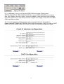
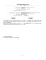
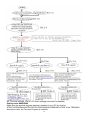
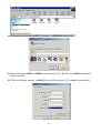
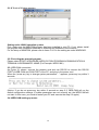
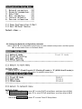
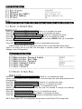
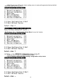
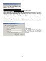
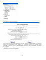
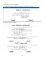
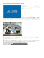
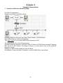
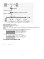
TVCWEB4 Web Server based camera with 3 auxiliary inputs User Manual 1 Contents 1 Overview of WEB-CAM ......................................................2 1. Product and accessories ........................................................................ 2 2. About your WEB-CAM............................................................................2 3. Description of WEB-CA ............................................................................ 4. System requirements ............................................................................. 5 5. Specifications ......................................................................................... 5 6. Service and support ............................................................................... 6 2 Installation...........................................................................7 1.Browser settings...................................................................................... 7 2.Terminal settings ................................................................................... 10 3 Watch Real-time Images ..................................................23 4 Various Settings and Their Functions............................25 5 Network Connections.......................................................35 1.WAN ...................................................................................................... 35 2.LAN ....................................................................................................... 36 6 Video Recording Software...............................................38 2 Chapter 1 Overview of WEB-CAM 1. Product and accessories The WEB-CAM package contains following items: A. WEB-CAM ...………………………………………….…………..…… 1 piece B. RS-232 connection cord (cross cable DB9 female)………….……. 1 piece C. Power adapter (DC 12V/1A)………….………………..…..…..……. 1 piece D. AC power cord………………….……………………………………… 1 piece E. User’s manual…………………………….…………….……………… 1 copy F. RJ45 cross link cable………………………………………………….. 1 piece G. Bracket…………………………………………………………………. 1 piece H. Remote/local recording/surveillance program CD-ROM………….. 1 copy 2. About your WEB-CAM WEB - CAM is a combination of Web Server and CCD camera that transmits compressed image to the URLs specified by customers. Users need a PC with a built-in browser (such as I.E. or Netscape) to link the WEB-CAM via the Internet. Once the connection is complete, users can immediately watch the real-time image on the far end. There is no need to install any other software for this application. The WEB-CAM can be used in an office, hospital, school, kindergarten, freeway, warehouse, factory, ATM machine, household security, airport, power plant, traffic control, etc., for remote watching and surveillance. By installing the remote/local recording/surveillance program CD-ROM (supports Windows OS only) included in this package, users can immediately watch and record images from up to 4 sets of WEB-CAMs or up to 16 sets of video cameras. 3 3. Description of WEB-CAM 4 1. DC input DC 12V IEEE 802.3 Standard Ethernet 10/100M bps base port for 2. RJ45 port Network connection. DB9 PIN cord connects to the PC monitor 3-1.RS232 DB9 connector 2 : RX 3 : TX 5 : GND PIN1 ON: update program mode 3-2.DIP switch OFF: normal mode PIN2~4 NO CONNECT 3-3. RESET switch Reset WEB-CAM system 4.Built-in Camera CCD camera with manual focusing 5. Image output 1 BNC connector video out, for the built- in CCD camera 6. Image input 2 BNC connector video in, for the external camera (CHANNEL 2) 7. Image input 3 BNC connector video in, for the external camera (CHANNEL 3) 8. Image input 4 BNC connector video in, for the external camera (CHANNEL 4) 9. Alarm input Photo couple GPIO input 1,2 (Sensor input) Normal: N.O. (NORMAL OPEN) Active: N.C. (NORMAL CLOSE) Power on: left LED (red) lit 10.Power/status indicator CPU operating: right LED (green) flashing Sending/receiving data: left LED (yellow) flashing 11. Network indicator Network connect: right LED (green) lit 4. System requirements WEB-CAM requirements: Ethernet system, like ADSL MODEM, CABLE MODEM, BRIDGE/ROUTER, etc., which is capable of providing, fixed IP, floating IP or DHCP. 5 Browser requirements: PC compatible system with 10 / 100M bps base Ethernet Port High/True Colour minimum 800x600 resolution Display Adapter Windows IE 5.0(above) or Netscape Navigator 4.0 (above) or Linux system browser. For the systems that are incompatible with a PC browser, please contact your local system distributor. 5. Specifications Hardware CPU: 32 bits RISC embedded processor Flash ROM: 512K Byte flash ROM Flash memory: 8M Byte RAM: 32M Byte SDRAM 1 piece of RS-232 with serial ports 1 piece of RJ-45 for 10/100M bps Ethernet 2 sets of GPIO ALARM to input connection Embedded O/S Video input 4CH(1built-in,3 external),1.0 Vp-p,75Ω,Composite,BNC,NTSC/PAL for automatic detection. Video output 1 CH 1.0Vp-p, 75Ω,Composite, BNC Built-in camera module CCD sensor NTSC: 537(H) x505 (V) PAL: 537(H) x597 (V) 1 LUX Auto Electronic shutter Auto White Balance Lens Manual focus 6mm/F2.0 Image compression JPEG 320 x 240, 176 x 144 Image adjustment Adjustment of brightness, contrast, saturation and hue; and 640x480 Zoom-in Communication protocol TCP/UDP/IP, ICMP, HTTP, FTP, SMTP, PPP, PPPoE, DHCP, NTP LAN interface RJ-45 for 10 /100M bps Ethernet Frame rate Max. 30 frame/second (@320x240,LAN, single channel) Event triggering & Response method Triggering: 2 sets, triggered externally Response method: e-mail images to specified URL or upload to FTP. “ALARM” displayed on screen. Installation IP setting: Browser setting or via RS-232 terminal equipment setting. System requirements Standard browser, such as Microsoft IE4.x above or Netscape Navigator 4.x above; can be executed on Win95/98/Me/2000/XP/NT, LINUX, MAC operation system. 6 Security Security password set by administrator. Operation temperature 5 ~50 (40 ~ 125 ) Humidity 20 ~80 % Power supply DC 12V, 1A Power consumption Less 8 watts Dimensions 167mm (length) x101mm (width) x 50mm (height) Weight 0.4kg (without power adapter & bracket) 6. Service and support Please contact the local distributor about any problems with your WEB-CAM or for the latest product information. 7 Chapter 2 Installation Before installation Connect the LAN and PC as Figure 2-1 for WEB-CAM setting. (Figure2-1) Use RJ-45 twisted-pair cord (attached in WEB-CAM package) or standard CAT-5 cable to connect PC and WEB-CAM. z Recommend to use attached power adaptor (output DC 12V / 1A, in package). z Prepare 3 external color-cameras (BNC connector) if you need to connect them to WEBCAM. If use terminal to executive WEB-CAM setting, the following additional preparation is required: z Be sure the RS-232 cables are on hand. (Attached in package) z Install the “Terminal Program” (MINICOM for LINUX OS) in your PC. z Connect the WEB-CAM to either the COM1 or COM2 port on your PC. 1. Browser settings z Please complete the following setting-up for initial use. 1-1. Setting-up IP address for your PC For Windows 98 Click START Æ SETTINGS Æ CONTROLL PANEL Æ NETWORK Æ Select TCP/IP Æ Select SPECIFIED IP ADDRESS. Set IP Address=192.168.1.2, Subnet Mask=255.255.255.0 and press OK For Windows 2000/XP Click START Æ SETTINGS Æ NETWORK AND CONNECTIONS Æ LOCAL AREA CONNECTION Æ Select INTERNET PROTOCOL (TCP/IP) Æ PROPERTIES Æ Select SPECIFIED IP ADDRESS and Set IP Address=192.168.1.2, Subnet Mask=255.255.255.0 and press OK (Notice: Upon the completion of setting, please resume your original PC-network parameters) 1-2. WEB-CAM quick browsing Refer to figure 2-1, after connecting your PC to the Internet, turn the power on and wait for about 30 seconds, type WEB-CAM IP address (default IP 192.168.1.1) in your web browser 8 (I.E. or Netscape), then you will see the WEB-CAM home page. Please select SETTINGSÆDATE & TIME CONFIGURATIONÆ select SYNCHRONIZE with computer time, click “Submit” and click “Home” to see the images. If there are other video cameras connected, please try to view those channels’ images. If the image is clear, then the WEBCAM is working normally. 1-3. Network parameters setting (please refer to chapter 5 Network Connections) Please select SETTINGSÆNETWORK CONFIGURATIONÆselect FIXED IP mode or DHCP MODE or PPPoE MODE, then click “Submit” to enter the following configuration page. 9 Click “Submit” to send out the setting and wait for about 15 seconds, then remove the power cord and the setting is complete. Upon the completion of the setting, please resume your PC original parameters. (Notice: WEB-CAM is unable to get on line if network parameter is not correctly setup. Please follow “the terminal settings” to conduct re-set). 2. Terminal settings The flowchart of terminal quick setting 10 2-1. Terminal settings: (Go to 2-2 if these settings have been completed) Setting under WINDOWS Make sure the terminal program has been installed in your PC by clicking STARTÆPROGRAMÆAPPLICATION PROGRAMÆCOMMUNICATION. If the TERMINAL shows the menu, the Terminal Program is installed. 11 z z If the Terminal Program is not installed, please click CONTROLÆADD/DELETE PROGRAM; select WINDOWS INSTALLATION PROGRAMÆCOMMUNICATION >DETAILS->; select TERMINAL; press OK; and then insert Windows CD for Terminal Program installation. Check the available COM ports by clicking CONTROLÆSYSTEMÆ ADMINISTRATORÆ CONNECTION PORTS (COM & LPT). If COMMUNICATION PORT (COM1) and/or COMMUNICATION PORT (COM2) shown, there is COM port available. If there are no COM ports available, please restart your PC and set up BIOS to activate COM port (COM1 & COM2). (Notice: If COM ports are occupied by mouse or modem, you have to find other available COM ports for your WEB-CAM setting) 2-1-1. Click the STARTÆPROGRAMÆAPPLICATION PROGRAMÆCOMMUNICATIONS and then click HYPER TERMINAL. 2-1-2.When LOCATION appears, then type ”Country/Area” and ”Area Code”; and then press ”Close”. (Notice You need to go through this installation procedure when you setup your terminal for the first time. If you provide sufficient information, this procedure will not appear again.) 2-1-3.If you use a modem, please choose “YES” and install the modem according to the installation procedure. 2-1-4.Please choose “Hypertrm.exe”. 12 2-1-5.Select icon and input name (For example web-cam) and press OK. 2-1-6.Choose either COM1 or COM2 for connection to PC. (Be sure the COM port selected works normally). 2-1-7.Set the “Bits per second” at 38,400 ;(B) and “Flow Control “(F) for none; and press OK. 13 2-1-8.Terminal Window appears. Setting under LINUX operation system First, make sure the MINICOM program has been installed in your PC. If not, please install the program from installation software or download the software via the Internet. For the setup of MINICOM, please refer to items F & G in the setting as under WINDOWS. 2-2. Executing the terminal program: Please select STARTÆPROGRAMÆAPPLICATION PROGRAMÆCOMMUNICATIONÆ TERMINALÆDIGRAMMATIC NAME (For Example: WEB-CAM.) 2-3. WEB-CAM connection: As Figure 2-1 shown, connect the network cord and use RS-232 to connect the RS-232 PORT of WEB-CAM and COM PORT of the PC, and plug in the power cord. When the “press any key to change system parameters….” appears, press any key within 3 seconds. (Notice: If you do not press any key within 3 seconds on step 2-3, WEB-CAM will run the default configuration settings. If system parameters are not correctly set, the WEB-CAM will not start. In this case, you need to restart your PC and execute the step 2-3 again). 2-4. WEB-CAM setting-up menu: 14 2-5. Setting-up Network configuration parameter 2-5-1. Press ”N” at configuration setup menu to enter network setup menu and then press “M” to enter select menu on Network Mode. 2-5-2. Press “F” (Fixed IP mode),“D” (Floating IP mode) or “P” (ADSL float IP mode) to continue the set up ; or press “Q” to return to network setup menu. For DHCP dynamic IP mode , press “D” to enter DHCP setup Menu, and then skip to 2-5-4 For ADSL dynamic IP mode , press “P” to enter PPPoE setup Menu, and then skip to 2-5-5 2-5-3. For Fixed IP mode , press “F” to enter Fixed IP Setup Menu . 15 Press ”H”, Enter the name of mainframe, and press “enter“ to complete the setup. Press ”I”, Enter fixed IP address. Press “y“ to complete the setup. Press ”P”, Enter IP port number, default is 80,max. can set to 65535,Press “y“ to complete the setup. Press “N”, Enter network mask. Press “y“ to complete the setup. Press “G“, Enter default gateway. Press “y“ to complete the setup. Press “D“,Enter DNS Server 1. Press “y“ to complete the setup. Press “S“, Enter DNS Server 2. Press “y“ to complete the setup. Press “Q“, Quit fixed IP setup menu. Return to configuration setup menu. 2-5-4. DHCP setup menu Press ″O″, Enter the name of the DHCP mail Server . Press “y“ to complete the Setup. Press ″M″, Enter the e-mail account No. of DHCP . Press “y“ to complete the setup. Press ″P″, Enter IP port number, default is 80, max. can set to 65535,Press “y“ to complete the setup. Press ″Q″, Quit DHCP setup menu. Return to configuration setup menu. 2-5-5. PPPoE setup menu 16 Press ″U″, Enter user’s ADSL account No. Press “y“ to complete the setup. Press ″P″, Enter user’s ADSL password. Press “y“ to complete the setup. Press ″O″, Enter user’s ADSL mail Server name. Press “y“ to complete the setup. Press ″M″, Enter user’s ADSL e-mail address. Press “y“ to complete the setup. Press ″I″, Enter IP port number, default is 80, max. can set to 65535,Press “y” to complete the setup. Press ″Q″, Quit PPPoE setup menu. Return to configuration setup menu. 2-5-6. Please enter ″P″ at configuration setup menu to enter password setup menu. (Notice: the setup can be set after the web page is opened, please refer to Chapter 4 Settings->User Configuration ) • Press ″A ″, Administrator password enable. Press ″y ″ to complete the setup. (Notice: administrators own all authority without limit including view and setup channels and all arguments) Press ″U ″, Enter administrator user name. Press ″y ″ to complete the setup. Press ″P ″, Enter administrator password. Press ″y ″ to complete the setup. Press ″G ″, Guest password enable. Press ″y ″ to complete the setup. (Notice: quests own the viewing authority only and not allowed to change any settings arguments) Press ″N ″, Enter guest user name. Press ″y ″ to complete the setup. Press ″S ″, Enter guest password. Press ″enter ″ to complete the setup. Press ″Q ″, Quit password setup menu. Return to configuration setup menu. 2-5-7. Please press ″D ″ at configuration setup menu to enter Date & Time setup menu. 17 (Notice: the setup can be set after the web page is opened. Please refer to Chapter 4 Settings->Date & Time Configuration) Press ″D ″, Enter current date. Press “enter“ to complete the setup. Press ″T ″, Enter current time. Press “enter“ to complete the setup. Press ″Z ″, Enter WEB-CAM time zone. Press “enter“ to complete the setup. Press ″S ″, Enter NTP Server’s IP address. Press “enter“ to complete the setup. (Note: defaulted at 210.59.157.10. If you cannot connect to that address within 10 seconds, you can change it to another NTP address such as 129.67.1.2 or 163.1.2.1 or 129.67.1.180 or 163.1.2.33) Press ″Q ″, Quit date & time setup menu. Return to configuration setup menu. 2-5-8. Please enter ″M″ at configuration setup menu and enter mail setup menu. (Notice: the setup can be set after the web page is opened, please refer to Chapter 4 Application->Notification) Press ″O″, Enter WEB-CAM e-mail Server. Press ″y″ to complete the setup. Press ″M″, Enter WEB-CAM owner’s e-mail address. Press ″y″ to complete the setup. Press “S“, Enter the recipient’s e-mail address to receive real-time static images. Maximum 5 e-mail addresses are allowed. Press ″y″ to complete the setup. Press ″0″, Send out the recipient’s e-mail addresses to receive real-time images when alarm 1 is triggered. Maximum 5 e-mail addresses are allowed. Press ″y″ as soon as to complete the setup. Press ″1″, Send out the recipient’s e-mail addresses to receive real-time images when alarm 2 is triggered. Maximum 5 e-mail addresses are allowed. Enter ″y″ as soon as to complete the setup. Press ″Q″, Quit mail setup menu. Return to the configuration setup menu. 18 2-5-9. Please input ″F″ on the status setting menu to setup all arguments that are default value then input ″y″ to confirm it. 2-5-10. Select “V“ in ‘Configuration Setup Menu’ to see the Version. Press any key to leave configuration setup menu. 2-5-11. Saving, setting-up and quitting configuration setup menu 19 Press ”Q”, Quit setup without saving data and then “y”. Press ”S″, Save data and quit and then “y”. 2-6. Initialize of Fixed IP mode: 20 2-7. Initialize of DHCP mode: WEB-CAM gets this IP 2-8. Initialize of PPPoE mode: 21 address WEB-CAM gets this IP address Chapter 3 Watch Real-time Images Connect WEB-CAM to PC to watch real-time images. 1. Enter IP address For fixed IP users Type in your WEB-CAM IP address in order to see the WEB-CAM homepage as shown in the following picture: 22 For dynamic IP (DHCP or ADSL) users Check your PC to find out WEB-CAM notification from WEB-CAM. Type in the IP address to access home page . (Notice: whenever you restart the WEB-CAM, a new IP address is required. The new IP address can be obtained from WEB-CAM notification in new e-mail. Furthermore, the user’s ADSL floating IP might be shut off by the network ISP after certain hours of connection. In this case, you have to re-link your WEB-CAM to new IP). 2. Input password If the “Guest Password Enable”(ref. Sect 2-5-6) is set, you have to type in the user’s name and password after you enter onto the main picture. You will be able to watch images after the verification processed. 3. Main menu Press “HOME” command on the left of the homepage. If you see the picture below, the installation is successfully completed. 23 Chapter 4 Various Settings and Their Functions The menu is on the left side of the homepage as follows: 24 1.Settings: 1-1. Setting-up User Configuration: You can set the user’s name, password and other functions for administrator or guests as well as the administrator’s e-mail address. After completing the input and selection, press “Submit” on either the upper or lower area of the homepage. If the picture blinks, the setting is completed. 1-2.Setting -up Camera Configuration: 25 You can set the image output size, image channel, image mode, and adjust the image parameter of various image channels for the camera. If you use the automatic switching, you can select the output channel and adjustment the time interval. Please input the new number and press “Submit” on either the upper or lower areas of the homepage. After completing the input and selection, press “Submit” on either the upper or lower area of the homepage. If the picture blinks, the setting is completed. 26 1-3. Setting-up Network Configuration: Network argument setup configuration (Network Configuration) as follows: To change any of the Network setting models above, please press “ Submit “ on the bottom to enter the next step as follows: 27 Setup any other parameter please press the button “Submit “ and wait for 15 seconds, then pull out the power cord to finish changing of the network configuration. (Notice: once network parameter setup has been changed, the web page you linked will be null. Please pull out the power cord and chang the network environment and reset the computer. If the new network parameter is wrong,the WEB-CAM will not be connected. Please refer to chapter 2: Terminal settings to do resetting. 1-4. Setting-up Date and Time Configuration: 28 The system has a built-in RTC function so you can set the system time of WEB CAM in three different ways (Synchronize with computer time, Synchronize with NTP server or set manually). After finishing the change, please press the button “ Submit “and click ”Home“ to get the home picture. (Reference NTP server time: 129.67.1.2, 163.1.2.1, 129.67.1.180 or 163.1.2.33,… ) 2. Applications: capable of taking the real-time image or sending the image out immediately to FTP or via email to notify the alarms are triggered. 2-1. Setting-up E-mail notification: 29 The alarm notification has to be set at ‘ enable’ for sending e-mail out. Both the maximum transmission time and the maximum interval of transmission of alarm notification are 60 minutes. Alarm 1 and Alarm 2 can be set at ch1 ~ ch4. A maximum of 5 e-mail boxes can be set for receiving real-time images generated by snapshots and alarms. 2-2. Setting-up Uploading Images to FTP: Enter FTP address and upload path to transmit continuous images or alarm triggered images to FTP. If FTP is in non-anonymous mode, please enter the user’s name and password. You can set the file name and select the file format such as overwrite, date & time, continual type (transmitting 1,024 graphic files), or continual type (transmitting 30 65,535 graphic files at most) to generate continuous files. After all files have been transmitted, the function of upload to FTP will be disabled. This function will be resumed by setting ‘enable’ again. (Notice: Uploading overwrite and date & time will not stop automatically. You have to manually disable it to stop uploading.) 2-3. Layout: This function allows users to setup their own logo and title: 2-3-1. Upload graph (The best format is JPEG and the limit size of the graph is 50K Byte) as the logo and description the use. It is acceptable to link the logo or background color of the website (please refer to the description as above picture) 2-3-2. Setup the title, color and background is acceptable (please refer to the description as above picture). 2-3-3. Setup the color and word and background is acceptable (please refer to the description as above picture). Input the new value please press “ Submit “and refresh the browser to finish the change. 3.Support: 31 Press Support → Log Report , you will see the folioing message. 4.Home: Press “ Home“ to watch the real-time image immediately. 5.Other software functions and cautions: 5-1. There are two standard image specifications– 320X240 and 176X144. 5-2. The single channel browser allows snapshots(to E-mail or window) and scaling up to 640X480. 5-3. Auto switch browsing allows scale up to 640X480. 5-4.When the administrator changes channels, the other users will receive the following message: Please press “Home“ in the left area of the homepage. The image will be cleared and then automatically switch to another picture. 5-5. If Alarm‘s Auto Switch is triggered, all users can see the following message. After the 32 alarm event is solved, the original picture will resume. (Notice: After the alarm is triggered, the WEB-CAM will not accept any other trigger signals unless the previous event is solved and the system is reset.) 5-6. In case the ‘all channel input’ or ‘single channel input’ is used, either “Alarm 1” or “Alarm 2” will be triggered, “ALARM” (in red) will appear in the upper-left corner. After the alarm event is solved, the original picture will resume. 5-7. Any thing such as freezing or motionless picture occurred, please press the “Reorganize” button or execute “Delete file” at Temporary Internet Files in your PC. Then your WEB-CAM will work normally. 5-8. If all functions of WEB-CAM run normally, but there are no images present, it might be due to your browser does not support JAVA script. In this case, you may download Microsoft JAVA VM from http://windowsupdate.microsoft.com/ , or SUN JAVA VM from http://java.sun.com/j2se/1.4/download.html (Notice: Firewall may block images.) . 33 Chapter 5 Network Connections 1. Connect to Wide Area Network (WAN) 1-1. Multi-IP Applications: Suitable for Fixed IP and ADSL clients. All WEB-CAMs are allowed to use either Fixed IP Mode or PPPoE Mode. Each WEB-CAM use individual IP address. Type http://<real IP> to connect WEB-CAM to remote/local PC. 1-2. Actual Single IP or Multi-IP Applications: All WEB-CAMs are allowed to use either Fixed IP Mode or PPPoE Mode through IP Sharing, NAT Server or NAT Router. The setup of server or router please refer to the suppliers’ operation manual . Settings for WEB-CAMs please use Fixed IP Mode. An example of using an actual IP address to several WEB-CAMs is as follows: 34 Actual IP address is 61.35.20.53 WAN Port of IP Sharing is 61.35.20.53 LAN Port is 192.168.0.1 (Notice: The TCP/IP Port number of each WEB-CAM is not allowed to be the same with others) All remote/local PCs (PC-A,B,C)can be linked to WEB-CAM by typing: http://61.35.20.53:3000 to get the first WEB-CAM http://61.35.20.53:3001 to get the second WEB-CAM http://61.35.20.53:3002 to get the third WEB-CAM …… Local PC-C can be linked to WEB-CAM by typing: http://192.168.0.2:3000 to get the first WEB-CAM http://192.168.0.3:3001 to get the second WEB-CAM http://192.168.0.4:3002 to get the third WEB-CAM …… . 2 Connect to Local Area Network (LAN) 2-1. Obtain DHCP Via Server 35 All WEB-CAMs are allowed to use DHCP Mode. All WEB-CAM share a virtual IP address(This IP address is provided by WEB-CAM Via Email) Local PC can be linked to WEB-CAM by typing http://<virtual IP> to get the WEB-CAM. 2-2.Connecting PC and WEB-CAM Via HUB: All WEB-CAM must be set up with Fixed IP Mode. Each WEB-CAM uses individual virtual IP address (under the same LAN) As shown above figure: Pc virtual IP address is 192.168.0.2 The local PC can be linked to WEB-CAM by typing: http://192.168.0.1 to get the first WEB-CAM http://192.168.0.3 to get the second WEB-CAM http://192.168.0.4 to get the third WEB-CAM …… 2-3. Connecting PC Straight to WEB-CAM: Please type http://192.168.0.1 in the local browser to link with WEB-CAM. 36 Chapter 6 Video Recording Software 1. System Requirements 1-1. Operation System: Windows 2000 or above 1-2. PC: CPU 800 MHZ or faster, SDRAM 256M or more. 1-3. Ethernet Card: 10/100M bps 1-4. VGA Card :1024x768 pixels or more 2. Function 2-1. Support 1 to 4 WEB-CAMs (up to a maximum of 16 video input) 2-2. Variable Multi-screen Display - 1, 4, 16; capable of zooming in/out for each picture 2-3. Recording and Playback 2-3-1 Independent recording for individual camera z Continuance Recording. zSchedule Recording: set start/end time, frequency of recording (frame/sec), period of recording (max. 1 week; min. 1 hour) 2-3-2 Save Record; setting the path and the files name for record saving 2-3-3 Search Record: use time range of recording to retrieve individual camera’s record (under same saving path). 2-3-4 Playback zPlayback and recording can be executed simultaneously zAdjustable playback speed (playback, quick forward, still) zRecorded record can be deleted. 2-3-5 Warning notification can be sent out via E-mail to the administrator. If ignore the warning, the new record will over-write the oldest record automatically. 2-3-6 Others Automatically record the system on/off, user name, time of login, start/stop time of recording. 2-4.Other Setup 2-4-1 WEB-CAM parameters ( Password, camera title, etc.) 2-4-2 Users Window Protection: Set personal password to lock the window to avoid the settings being changed or shifted. 2-4-3 Motion Detect z Area to be detected. z Preset the time period to be detected. z Alarm transmission via E-mail when the motion detection is set enable. 2-5.MgrViewer Software: for the record playback and convert the record to AVI mode. 2-6. MgrWatch: for main program eDogMgr auto run function. Please read the detail of content of “Help” in the CD. 3. Others A WEB-CAM’s image or images can be browsed (such as WINDOWS IE5.0), or recorded (use our e-Dog Manager recording program) by many users simultaneously, however, the following noticed should be taken. 37 3-1. The e-Dog Manager Recording Program has higher installation priority. In other words, the original WEB-CAM settings, including all "Camera Configuration" setting items, can be changed or influenced by e-Dog Manager Program. 3-2. Only one "Camera setting" parameter of the e-Dog Manager Program is allowed to use in a WEB-CAM or WEB-CAMs that share with one IP address and port number. For example, if one user is selecting “single mode”, other user should not change it. Otherwise, it might cause unexpected malfunction. 38