1
SecureLinx Spider™
User Guide
Part Number 900-495
Revision B November 2007
Copyright & Trademark
© 2007, Lantronix. All rights reserved. No part of the contents of this book may be
transmitted or reproduced in any form or by any means without the written permission of
Lantronix. Printed in the United States of America.
Ethernet is a trademark of XEROX Corporation. UNIX is a registered trademark of The
Open Group. Windows 95, Windows 98, Windows 2000, Windows XP are trademarks of
Microsoft Corp. Netscape is a trademark of Netscape Communications Corporation.
LINUX GPL Compliance
Certain portions of source code for the software supporting the SLS family are licensed
under the GNU General Public License (GPL) as published by the Free Software
Foundation and may be redistributed and modified under the terms of the GNU GPL. A
machine readable copy of the corresponding portions of GPL licensed source code is
available at the cost of distribution.
Such source code is distributed WITHOUT ANY WARRANTY, INCLUDING ANY
IMPLIED WARRANTY OF MERCHANTABILITY OR FITNESS FOR A PARTICULAR
PURPOSE. See the GNU General Public License for more details.
A copy of the GNU General Public License is available on the Lantronix Web Site at
http://www.lantronix.com/ or by visiting http://www.gnu.org/copyleft/gpl.html. You can also
obtain it by writing to the Free Software Foundation, Inc. 59 Temple Place, Suite 330,
Boston, MA 02111-1307 USA.
Contacts
Lantronix Corporate Headquarters
15353 Barranca Parkway
Irvine, CA 92618, USA
Phone: 949-453-3990
Fax:
949-453-3995
Technical Support
Online: www.lantronix.com/support
Sales Offices
For a current list of our domestic and international sales offices, go to the Lantronix web
site at www.lantronix.com/about/contact .
Disclaimer & Revisions
Operation of this equipment in a residential area is likely to cause interference, in which
case the user, at his or her own expense, will be required to take whatever measures
may be required to correct the interference.
Note: This equipment has been tested and found to comply with the limits for
Class A digital device pursuant to Part 15 of the FCC Rules. These limits are
designed to provide reasonable protection against harmful interference when the
equipment is operated in a commercial environment. This equipment generates,
uses, and can radiate radio frequency energy and, if not installed and used in
SecureLinx Spider User Guide
2
Contents
accordance with this User Guide, may clause interference to radio
communications. Operation of this equipment in a residential area is likely to
cause interference, in which case the user will be required to correct the
interference at his own expense.
The user is cautioned that changes and modifications made to the equipment
without approval of the manufacturer could void the user’s authority to operate
this equipment.
Changes or modifications to this device not explicitly approved by Lantronix will void the
user's authority to operate this device.
The information in this guide may change without notice. The manufacturer assumes no
responsibility for any errors that may appear in this guide.
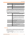
Date
Rev. Comments
3/07
11/07
A
B
Initial Document
Changed baud rate default to 9600; added Detector utility for assigning
IP address; added ability to enable drive redirection, configure
backup/restore, and reset factory defaults; introduced a CLI and
commands.
Contents
1: Preface
6
Purpose and Audience________________________________________________ 6
Additional Documentation _____________________________________________ 6
2: Introduction
7
Features___________________________________________________________ 7
Functionality________________________________________________________ 8
Technical Specifications ______________________________________________ 8
3: Installation
11
Package Contents __________________________________________________ 11
Configuration Planning_______________________________________________ 11
Batch vs. Individual Setup ____________________________________________ 12
Installation and Network Settings_______________________________________ 13
Target Computer Setup ______________________________________________ 16
Client Setup _______________________________________________________ 18
Network Environment________________________________________________ 19
Power____________________________________________________________ 19
4: Web Browser Access
20
5: Remote System Control
22
KVM Console ______________________________________________________ 22
Telnet/SSH________________________________________________________ 29
6: Virtual Media
31
Floppy Image ______________________________________________________ 31
CD-ROM Image ____________________________________________________ 32
Drive Redirection ___________________________________________________ 33
Virtual Media Options________________________________________________ 36
7: User Management
37
Local vs. Remote Authentication _______________________________________ 37
Local User Management _____________________________________________ 37
User Permissions___________________________________________________ 39
8: KVM Settings
40
User Console ______________________________________________________ 40
SecureLinx Spider User Guide
4
Contents
Keyboard/Mouse ___________________________________________________ 42
Video ____________________________________________________________ 44
9: Device Settings
46
Network Settings ___________________________________________________ 46
Security __________________________________________________________ 47
Certificate_________________________________________________________ 49
Serial Port ________________________________________________________ 51
Date/Time ________________________________________________________ 52
Remote Authentication_______________________________________________ 54
Event Log_________________________________________________________ 55
SNMP____________________________________________________________ 57
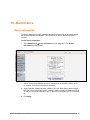
10: Maintenance
58
Device Information __________________________________________________ 58
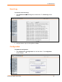
Event Log_________________________________________________________ 59
Configuration ______________________________________________________ 59
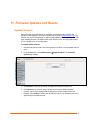
11: Firmware Updates and Resets
61
Update Firmware ___________________________________________________ 61
Reset ____________________________________________________________ 62
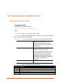
12: Command Line Interface (CLI)
63
Introduction to Commands____________________________________________ 63
Configuration Commands ____________________________________________ 65
Connect Commands ________________________________________________ 65
SSH Key Commands ________________________________________________ 65
History Commands _________________________________________________ 67
Version Command __________________________________________________ 67
A: Troubleshooting
68
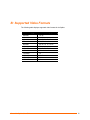
B: Supported Video Formats
70
C: Technical Support
71
D: Compliance
72
E: Warranty
73
SecureLinx Spider User Guide
5
1: Preface
Purpose and Audience
This guide describes how to install, configure, use, and update the SecureLinx Spider
device. It is for users remotely and securely monitoring and control of one target
computer system by one or more remote users.
Additional Documentation
The following guide is available on the product CD or the Lantronix Web site:
www.lantronix.com.
Document
Description
Spider View User Guide
Details instructions on using the Spider View utility.
SecureLinx Spider Quick Start Guide
Provides an overview of using the Spider.
SecureLinx Spider User Guide
6
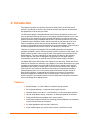
2: Introduction
This chapter introduces the Lantronix SecureLinx Spider (SLS) line of KVM-over-IP
devices. It provides an overview of the products, lists their key features, and describes
the applications for which they are suited.
The SecureLinx Spider is a distributed KVM-over-IP device designed to remotely and
securely provide monitoring and control of one (target) computer system by one or more
remote users. The remote user (client) accesses the Spider over a local or wide area
network connection using a standard web browser. The Spider provides secure, remote
IP-based access to Keyboard, Video, and Mouse (KVM) on the attached server, and
makes it available to anyone who can access the Spider’s IP address. Spider is an
evolution of the traditional remote KVM switch into a compact package, is light enough to
be cable supported from the back of a server, and takes up no rack space.
There are four models: one with both PS/2 and USB keyboard/mouse interfaces
(software selectable), one for USB-only systems, and two variations of cable length. The
Spider is unique in that it is low-enough in power consumption to be powered from the
attached server. The color-coded plugs on the ends of the cables for the keyboard,
mouse, USB port and video are designed to plug directly into the target system’s
corresponding connectors. An optional external AC/DC power supply is available.
The Spider differs from other KVM-over-IP switches in several ways. Unlike rack mount
KVM-over-IP switches, the allocation of one Spider per computer allows add-as-you grow
scalability and guarantees non-blocked BIOS-level access to mission-critical servers
regardless of the number of remote users or servers that need access. Also, Spider is
unique in that it uses Lantronix SwitchPort+ technology to incorporate two hardwareswitched Ethernet ports, one for the primary network connection and the second for
daisy-chaining Spiders, or aggregating other Ethernet connections (for example, a
dedicated management LAN port on the controlled system). This provides a costeffective solution in environments where numerous cable drops and distance limitations
can be a challenge when adding servers.
Features
Browser based – no client software or special licensing required
Server-powered design – no external power supply required
Attaches directly to the server – zero footprint (no vertical rack space required)
Ideal for small branch offices, campuses, or distributed systems environment
Totally non-blocking and scalable (add 1 host at a time)
Incorporates Lantronix SwitchPort+ technology allowing Spiders to be cascaded
or share a host’s Ethernet connection
No video degradation with long Cat-5 cable runs
Virtual media support (use remote source to boot / install files on host)
SecureLinx Spider User Guide
7
2: Introduction
Built-in serial RS-232 port can be configured for serial console access or remote dial
in access
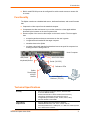
Functionality
The Spider contains an embedded web server, dedicated hardware, and control firmware
that:
Captures the video output from the attached computer
Compresses the video and serves it up over the network to a Java applet window
launched by the browser on the user’s system which
Draws a replica of the server’s video output on the user’s monitor. The Java applet
then
accepts keystrokes and mouse movements on the user’s system
recognizes those intended for the target computer
transmits those to the Spider
emulates a physically attached keyboard and mouse to spoof the computer into
thinking the user is sitting next to it
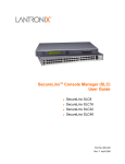
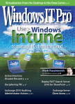
Host Computer
HD15 VGA Video
USB/Power
Keyboard/Mouse
Serial (RS-232)
Indicator LEDs
Spider
Distributed
KVM/IP
Module
10/100Base-T
Ethernet (TCP/IP)
Technical Specifications
Security
−
−
−
−
−
−
Secure encryption of keyboard, mouse, and video data
IP Source Address Filtering
Remote Authentication: LDAP, RADIUS, Active Directory
User/Group management with permissions control
Configurable port numbers (HTTP, HTTPS, Telnet, SSH)
Selective disable of Telnet/SSH
Target Server
Requirements
−
Supports Multiple Operating Systems: Windows
98/2000/2003/XP/Vista, Unix, Linux, or MAC OSX 10
Power/keyboard/mouse: 2 USB ports; or 1 USB and 1 PS/2 keyboard
and 1 PS/2 mouse connector
−
SecureLinx Spider User Guide
8
2: Introduction
Client System
Requirements
−
Video Interface: HD15 VGA video output (up to 1280x1024@60Hz)
−
Internet Explorer 6.0+, Netscape 5.0+, Mozilla 1.0+, FireFox 1.0+,
Safari 2.0+
PIII Processor equivalent or better (recommended)
Sun Java 2 Runtime Environment
Telnet/SSH client for command line (CLI) access
−
−
−
Optional Items
−
Optional DC power supply with international adapters (100-240VAC,
50-60 Hz; 5 VDC @ 1A; USB “Mini-B” Type jack)
Interfaces
−
−
−
−
Network: One 10/100Base-T Ethernet Port with activity indicators
(RJ45)
Cascade: One 10/100Base-T Ethernet Port with activity indicators
(RJ45)
Serial: RS-232, up to 115,200 bps
Keyboard/Mouse: PS/2 or USB
Video: HD15 VGA
Environmental
−
−
−
−
Operating: 0º to 45º C (32º to 115º F)
Storage: -20º to 70º C (-4º to 158º F)
Humidity: 0 to 95% RH (non-condensing)
Heat Dissipation: 4 Watts (14 BTU/hr)
Power Requirements
−
−
Input: 5 VDC @ .8A max. (server powered)
Optional Auxiliary DC power supply available for redundancy
Dimensions (H x W x D)
−
−
13.2 x 5.8 x 3.1 cm (5.2 x 2.3 x 1.2 in)
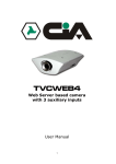
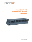
Refer to Figure 2-1 for cable dimensions
Weight
−
185g (6.6 oz)
Shipping Weight
−
.5 kg (1.0 lbs)
−
SecureLinx Spider User Guide
9
2: Introduction
Figure 2-1 Spider Cable Dimensions
SecureLinx Spider User Guide
10
3: Installation
This chapter describes how to install the SecureLinx Spider.
Package Contents
In addition to the Spider distributed KVM/IP module, the box contains the following items:
Null modem DB9F to RJ45 serial cable
Mounting kit
Quick Start Guide
CD-ROM containing documentation and utilities
An optional external AC/DC power supply is available.
Configuration Planning
Factors to consider when determining how the Spider will be used in an environment:
Keyboard/Mouse Interface
The USB interface is typically preferred as it provides better remote cursor tracking.
Some older systems do not have BIOS supporting USB human interface devices or there
may not be two available USB ports. In these cases, the PS/2-interface model may be
required; note that for this model the USB or PS/2 interface keyboard/mouse may be
selected via software.
Spider Serial Port
The RS-232 port on the Spider is used for initial configuration of setup parameters, but it
can subsequently be used to connect to a target’s COM port. The Spider allows remote
users to Telnet or SSH to that port, eliminating the need for a separate box to perform
serial command line management. Alternatively, the serial port can be used for PPP
connection to the Spider’s user interface so that remote users can access the Spider via
a modem or other serial interface. This could be either the primary network connection or
a backup in case the primary LAN connection is unavailable.
Redundant Power
The Spider draws all of its power from the attached server, eliminating the need for
external power supplies. Note that if the server loses power, the Spider loses power as
well. With an optional auxiliary DC supply fed from an independent AC power source, the
Spider will always have power regardless of the state of the server.
SecureLinx Spider User Guide
11
3: Installation
Second Ethernet Port
The Spider incorporates a hardware Ethernet switch connecting the external two ports
and the internal CPU for many possible configurations. The first port is required for
connection to the network.
Potential uses for the second Ethernet port:
Tying all the Spiders in a rack together so that only one external network connection is
required. While this configuration physically is a chain, logically each Spider is
addressed directly from the outside network. Because the data from the Spider at the
end of the chain does need to traverse the entire series of switches, latency increases
and hence responsiveness degrades with the number of devices. A maximum of 16
Spiders in a chain is recommended, though this is a function of the type of application
and acceptable level of response. If the switch to which the Spider chain is networked
supports Spanning Tree, the first and last devices in the chain may both be connected
to the same switch to provide resilience against a single point failure.
Connecting to the attached server’s LAN management port; an external management
network can then interface to both the Spider and the server via one cable.
Connecting to the attached computer’s main LAN port. If physical isolation of
management data and user data is not a concern, a single LAN cable can provide
connectivity to both Spider and computer, conserving a switch or router port.
Aggregating any other Ethernet connection as a general-purpose switch port.
Batch vs. Individual Setup
It may be necessary to deploy a batch of Spider devices at once. In that case, stage them
on a bench for pre-configuration before attaching them to their respective computers.
Some tips for configuring a batch of Spiders:
The keyboard/video/mouse connections are not required for setup. All you need are a
source of power and a serial connection to set up the network parameters, and an
Ethernet connection to access the administration user interface.
The quickest and easiest source of power is the auxiliary DC input. DC supplies are
available from Lantronix under order number 520-085-R. If using a third party charger
with mini-USB connector, make sure it is 5V@1A regulated (“Efficiency level III” or “IV”
is an indicator that it is a switching supply and hence well regulated) with an adequate
cable.
Tag each Spider with its IP address or write it on the serial number label on the
bottom.
SecureLinx Spider User Guide
12
3: Installation
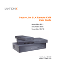
Installation and Network Settings
Figure 3-1Serial and Auxiliary Power Port
RS-232 Pinouts
1
2
3
4
5
6
7
Auxiliary Power
Connector (for
optional power cable)
RTS (out)
DTR (out)
TX (out)
GND
GND
RX (in)
DSR (in)
RS-232 Serial Port
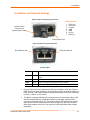
Figure 3-2 Ethernet and Cascade Ports
RJ45 Ethernet Port
RJ45 Cascade Port
Indicator LEDs
Pwr1
Blue
Power Good indicates adequate power from source 1 (USB1)
Pwr2
Blue
Power Good indicates adequate power from source 2 (USB2 or
PS/2)
SysOK
Green
Blinks upon bootup. Steady when up and healthy
Video
Green
Video is coming from target server (Vsync present)
Unit ID
Orange
Optionally lit to assist in finding unit
1. Plug the RJ45 end of the included serial cable into the Spider’s serial port. Plug the
DB9F end into the serial (COM) port of a PC/laptop running a terminal emulation (e.g.
HyperTerminal). The default serial port settings are 9600 bits per second, 8 data bits,
no parity, 1 stop bit, no flow control.
2. The Spider is typically powered by the attached server. Plug the Spider video, USB,
and PS/2 keyboard/mouse (if applicable) cables into the target computer (this is
required for the device to boot up). The two blue power LEDs will illuminate and the
green system OK LED flashes to indicate that it is booting up. Bootup is complete
within approximately one minute. The system OK LED stops flashing and remains
illuminated.
SecureLinx Spider User Guide
13
3: Installation
3. Upon bootup, the terminal window displays the login prompt. To change the default
IP auto configuration from DHCP to a static IP address, type config and press
Enter.
4. At the IP autoconfiguration prompt, type none and press Enter.
5. Follow the prompts to enter the unit’s IP address, subnet mask, default gateway, and
LAN interface information.
6. Type Y, following by Enter, to accept the changes. The system takes several
seconds to update the internal protocol stack and display the updated information.
7. Plug an Ethernet cable connected to your network into the Ethernet port. The Link
LED illuminates.
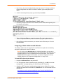
Assigning a Static Address with Detector
The Detector software is on the product CD. Use Detector to replace an automatically
assigned IP address with a static IP address.
Note: If you try to run detector2.exe on a network shared drive, you may get a
security exception. We recommend that you run the program on the CD or copy the
detector2 directory to your local hard drive and run it from there. If you must run
detector2.exe from a network shared drive, you need to change your security
settings using the" .NET Framework Configuration" or "caspol" tool.
To install .NET required by the Detector:
1. Double-click detector2.exe on the product CD.
2. If a "The application failed to initialize properly (0xc0000135), click OK to terminate
the application" message displays, you need to install .NET Framework.
3. Obtain the .NET Framework redistributable package from the Spider CD. It is also
available as a stand-alone executable file, Dotnetfx.exe. You can download this from
Microsoft at:
http://www.microsoft.com/downloads/details.aspx?FamilyID=0856EACB-43624B0D-8EDD-AAB15C5E04F5&displaylang=en
SecureLinx Spider User Guide
14
3: Installation
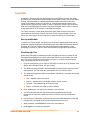
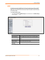
To use Detector to set the IP address:
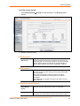
1. Open the Detector software. The Lantronix Detector window opens.
Lantronix Detector Window
2. From the Timeout drop-down menu (in the toolbar), select the number of
milliseconds before the search stops. The default is 3000.
3. Click the Search icon
displays.
. A list of Lantronix Ethernet devices on the network
Detector Device List Window
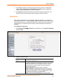
4. If the Spider has an automatically assigned IP address and you want to change it,
select the Spider and click the Network Settings icon
Settings window displays.
SecureLinx Spider User Guide
. The Enter Network
15
3: Installation
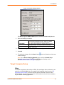
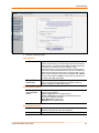
Figure 3-3. Network Settings Window
The Device Type and MAC Address (Ethernet Address) fields identify the unit.
5. Enter the following information:
IP Address
Subnet Mask
Default Gateway
An IP address that will be unique and valid on your network
and in the same subnet as your PC. There is no default.
Note: Enter all IP addresses in dot quad notation.
The subnet mask specifies the network segment on which
the Spider resides. To accept the default, leave blank.
IP address of the router for this network. To accept the
default, leave blank.
6. Click OK. A message confirms that your network configuration has been sent.
7. Click OK.
8. To confirm the change, click the Search icon
network settings.
and verify that the unit has new
Note: On the Device SettingsÆNetwork page, make sure Disable Setup
Protocol is not selected in the Network Miscellaneous Settings section.
See Miscellaneous Network Settings on page 47.
Target Computer Setup
Video
The Spider recognizes a wide variety of VESA, Sun, and Apple video resolutions up to a
maximum of 1280x1024@60 Hz; the complete list of supported video formats is in B:
Supported Video Formats. In order to minimize power consumed in the server and
attached Spider, set the monitored server’s video resolution to the minimum necessary
for your remote monitoring application.
SecureLinx Spider User Guide
16
3: Installation
1024x768 is recommended or 800x600 if connecting the Spider over a wide area network
rather than a LAN.1280x1024 may be used for applications demanding higher resolution,
however it consumes more network bandwidth. The other supported formats are
recognized by the Spider, but may offer difficulty if the timing does not comply with the
applicable standard. The Spider supports the extended display identification data (EDID)
standard for informing the attached computer of its supported video formats.
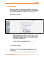
On a Windows target system, select Control PanelÆDisplayÆSettings. Modify the
screen resolution value as necessary.
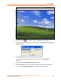
Select Control PanelÆDisplayÆSettingsÆAdvancedÆMonitor. Modify the screen
refresh rate (consult the appropriate documentation when using an atypical video card
or another operating system on the target computer). Since the server's video output
is driving the Spider and not a monitor, a refresh rate higher than 60 Hz has no effect.
For Linux systems, edit the Xfree86 file XF86Config to disable formats that are not
supported or not VESA standard timing; a reboot is required.
If you are using a special video card or another operating system on the target, consult
the appropriate documentation.
Solaris servers may need to be set to output H+V sync, not composite sync. The powerdown-monitor settings in the operating system’s power management have no effect on
the Spider’s internal operation and network interface, but if the attached server is in a
monitor power-down mode the client application displays “No Video” and the Video LED
will be out. The “Video” LED on the Spider actually monitors the vertical sync signal, not
the video data itself.
Background wallpaper and desktop appearances do not have any particular limitations,
although Microsoft Active Desktop and Linux graphical interfaces’ virtual desktop are not
supported. If bandwidth is a concern, plain backgrounds are preferred.
Mouse
Mouse to cursor synchronization has long been a troublesome issue with digital KVM
interfaces. PS/2 mice transmit incremental information about movement over a period of
time, not an absolute measurement; the driver in the operating system then translates to
distance based on the local screen resolution and applies linear or nonlinear acceleration
mappings. When a remote client system is communicating with the target system,
settings and screen resolutions on both sides of the connection must be taken into
account in order to get natural mouse-to-cursor tracking. Use the USB keyboard/mouse
when supported by the target computer. Unlike the PS/2 interface, a USB mouse uses
absolute coordinates rather than relative coordinates and hence does not present the
difficulties in translation between local and remote systems. On the PS/2 model Spider,
when the keyboard/mouse interface is set to Auto it will first attempt to use the USB
interface and only if it does not detect support in the attached OS will it fall back to PS/2.
There are no restrictions on the mouse settings of the client systems. And as a general
rule, no special care must be taken on setting mouse parameters of target systems when
using the USB mouse interface. For the PS/2 interface, performance (tracking) and
synchronization can be optimized by removing any special acceleration or nonlinear
ballistics. For several common operating systems:
On a Windows target system, select Control PanelÆMouseÆPointer Options. Set
the pointer speed to medium and disable Enhanced pointer precision.
Linux graphical interfaces. Set Mouse Acceleration to exactly 1 and threshold to
exactly 1. Also, select Other Operating Systems on the Spider mouse settings page.
SecureLinx Spider User Guide
17
3: Installation
Sun Solaris. Adjust mouse settings via the CDE control panel to “1:1, no acceleration”
or via “xset m 1”.
Mac OS X. Set Spider to Single Mouse Mode.
Serial
If you plan on using the Spider to Telnet or SSH to the target system’s serial port, set that
port to match the Spider’s equivalent settings. The Spider’s default serial settings are
9600 bps, 8 data bits, 1 stop bit, no parity, and no handshake. The pinout of the included
cable matches a standard DB9 COM port.
Cabling
Connections for video, USB, and keyboard/mouse are integrated into the Spider. Do not
use extension cables; plug the Spider directly into the appropriate ports on the host
system. If using the serial port, cable it to the appropriate COM port on the server. The
second Ethernet port (cascade) may be used to connect to the target computer’s
management LAN port or main LAN port, or to chain Spiders. When connecting the
Ethernet ports, either straight through or crossover cables may be used, as the Spider
has both auto-polarity and auto-crossover correction. Although both the port marked
Ethernet and the port marked Cascade are Ethernet interfaces, you must use the port
marked Ethernet if using only one Ethernet interface.
When chaining Spiders, bring the outside network cable in to the left Ethernet port of
the first Spider.
Connect the right Cascade port to the left port of the next Spider in the chain.
Repeat as necessary. The last Spider in the chain will have its right port unoccupied,
unless cabling in a loop for redundant connection.
The downside to chaining Spiders is that a break in the cabling or device failure results in
a loss of network connectivity for all Spiders downstream of the fault. This can be averted
if the switch or router to which the Spider chain attaches supports Spanning Tree, and
has it activated. In that case, the last Spider can have its Cascade port tied back to the
same switch so that there is a redundant outside connection. The Spanning Tree protocol
implemented in the switch will disable one of the two network connections while the loop
remains complete; data will flow in only one direction around the loop. If the loop is
broken, it activates both connections, so that data can flow in both directions. All Spiders
will be accessible except the one immediately downstream from the break or down unit.
Do not try this without Spanning Tree in place.
Client Setup
Two mechanisms are provided for monitoring Spider-connected targets at client systems.
Spider View is a standalone Windows application that can locate, manage, and access
multiple Spiders from an integrated view. Spider View requires a client to be running
Windows XP or later and have ActiveX controls enabled. Please refer to the separate
Spider View User Guide for instructions on installation and operation of Spider View.
For platform-independent management, each Spider contains an embedded web server
that delivers web pages and Java applets. The client system must have a web browser
(Spider supports browsers such as Internet Explorer 6.0+, Netscape 5.0+, FireFox 1.0+,
and Safari 2.0+) in order to access and administer the Spider. To run the actual Remote
Console window and manage the target system, a Java plug-in is also required. The
SecureLinx Spider User Guide
18
3: Installation
Microsoft Java Runtime Environment version 1.1 or later is supported, but the Sun JRE
1.4 or later is preferred.
Network Environment
The connection between client and Spider must be open to IP traffic and have TCP ports
80 (HTTP) and 443 (HTTPS) open. Firewalls and NAT devices may need to be
configured to support this; consult your system administrator. The TCP ports used by the
Spider may be changed at Device Settings ÆNetwork.
When idle, the Spider generates minimal network traffic but when images are rapidly
changing on the host system and image quality is set to the maximum there can be
bursts of traffic exceeding 10 mbps; fast Ethernet connections are recommended. In a
local area network, the responsiveness of the Remote Console window will be affected
by traffic; a switched network environment is advised.
Power
The Spider is low enough in power consumption (under 4 watts) to draw its power from
the attached computer. However, it requires all cables to be plugged in to receive
sufficient power. Plug in both USB cables or USB plus PS/2 cables. The Pwr1 LED
indicates that power is available on the first USB port. The Pwr2 LED indicates that
power is available the second USB port, or the PS/2 ports. The Spider will not start up
until both Pwr1 and Pwr2 LEDs are on. It then begins to blink the SysOK LED, which will
continue to blink while the boot process continues. The Spider is Linux-based, and takes
about a minute to boot. When the SysOK LED is on steady, the Spider is up and ready to
communicate.
The Spider can also derive power from an external DC supply. DC supplies are available
from Lantronix under order number 520-085-R. The DC supply is most useful as a
backup, as the Spider will otherwise lose power if the attached computer does.
In addition to power-on reset, the Spider can also be rebooted from the user interface,
from the serial port, or by clicking the reset switch through the pinhole on the back of the
body.
SecureLinx Spider User Guide
19
4: Web Browser Access
The SecureLinx Spider controls a target computer by redirecting its human interface
peripherals of keyboard, mouse, and video screen to one or more other (client)
computers. The Spider achieves this by serving up web pages and launching a Java
applet across the network connection to the client using standard protocols (such as IP,
TCP, and HTTP/HTTPS). The Java applet window running on the client system appears
as a copy of the target computer’s screen. This replica is the Remote Console (or
Remote Console).
Note: The Spider supports browsers such as Internet Explorer 6.0+, Netscape
5.0+, FireFox 1.0+, and Safari 2.0+.
When using the Spider View application on Windows, refer to the Spider View User
Guide. This section refers to the Spider connection via a web browser.
1. Access the Spider over the network using a web browser by entering:
https:// (for a secure SSL connection) or http:// (for an insecure connection)
and its IP address in the address bar. The browser must accept cookies for login.
2. Enter your user name (default is sysadmin) and password (default is PASS) at the
prompt. The Spider home page displays.
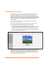
After passing authentication, the Spider opens the home page, from which the Remote
Console or Telnet Console may be launched. The home page contains a snapshot of the
target system’s video in the Remote Console Preview window, various pieces of
information in the Session Info box, and a menu bar along the left side. The top frame,
visible on all pages, includes a Logout button.
SecureLinx Spider User Guide
20
4: Web Browser Access
At this point, you are logged in with all permissions to make changes to configuration and
user database. You may then set the unit up for either local or remote authentication for
other users, and define their permission level. As sysadmin, you may also make changes
to the hardware settings, establish configuration parameters, and perform maintenance
operations.
SecureLinx Spider User Guide
21
5: Remote System Control
The Spider’s primary function is running the Remote Console (Remote Console). The
Remote Console window has settings that apply each time a user launches it. Other
settings may be applied within the window itself. By scaling the window down in size, it is
possible to have multiple Remote Console windows open, allowing interaction with
multiple target systems.
KVM Console
To launch the Remote Console window:
1. From the Main Menu, select Remote Console Æ KVM Console to launch the
Lantronix Spider Remote Console. The Remote Console window may open in the
foreground or in the background. If it launches in the background, click on the icon to
bring the window to the front.
2. Alternatively, launch the Remote Console from the Home page by clicking the link
above Remote Console Preview.
The Remote Console window shows a real-time replica of the video output from the
target system (mimicking a monitor plugged directly into the remote computer). When the
local computer’s focus is within the Remote Console window, mouse movements and
keystrokes are transmitted to the remote computer. The title bar of the window shows the
SecureLinx Spider User Guide
22
5: Remote System Control
IP address of the Spider providing this view (Useful when multiple windows are open on
the client system).
The Remote Console window is like any other window on the client system. It may be
minimized, maximized, or scaled in either direction.
Console Window Components
Title bar and IP
address
Toolbar
Button keys
Main viewport
Information Bar
Main Viewport and Scroll Bars
When first launched, the full virtual screen of the target computer is mapped pixel-forpixel to the console window’s main viewport. As a result, if the target is running at a
resolution less than that of the client, the entire screen is visible in the Remote Console
window. If the resolution is such that the screen does not fit, scroll bars are available in
the Remote Console window to move the viewport around within the target’s screen. The
virtual screen size of the target may also be scaled down to match the Remote Console
window.
Button Keys
Along the top there are Button Keys that have been defined to send special keycodes
directly to the target computer.
Toolbar
The top toolbar has a number of buttons for one-click access to functions, and a pulldown menu where other options may be reached. The icons vary depending on which
keyboard interface is active.
SecureLinx Spider User Guide
23
5: Remote System Control
Access Virtual Media
The leftmost diskette icon is used to activate the Virtual Media toolbar.
Auto Adjust Video
This button activates the Auto Adjust Video function. When first opening the
Remote Console window, it is recommended to click this button to ensure the
Spider has locked on to the video format on the attached computer. Also, click
this button if there is an offset from the proper horizontal or vertical start position
relative to the target screen (black bars to the right, left, top, or bottom of the
main viewport, or a distorted video).
Sync Mouse, Single/Double Cursor
These icons appear when the PS/2 mouse interface is active.
Options
The pull-down menu provides access to a number of options and features.
Information Bar - Connection
The left side of the information bar indicates whether the connection is encrypted
(Console(SSL)) or unencrypted (Console(Norm)).
Information Bar - Resolution
Displays the horizontal by vertical resolution of the target system’s video.
Information Bar - Network Traffic
Displays the approximate number of bytes per second incoming and outgoing to the
window. An indication of the number of frames per second (fps) updated is also
displayed. Incoming data is generally comprised of video updates. Outgoing data is
generally comprised of keystrokes and mouse movements. When the target screen is not
changing, In should be low or zero. If not, click the auto-adjust button. The amount of
network traffic is a function of the detail in the captured screen, the rate at which the
screen is changing, and the video encoding settings.
Concurrent Access State
One user is connected to the Remote Console
Multiple users are connected to the Remote Console
This user has exclusive access to the Remote Console. No other clients may access
the target system until exclusive access is disabled.
Another user has exclusive access to the Remote Console. No other clients may
access the target system until exclusive access is disabled by that user, or until that
user closes their Remote Console window.
Monitor Only State
The far right icon shows whether this client may interact or simply view the target
computer.
Monitor Only is disabled; keyboard and mouse may interact with the target.
Monitor Only is enabled; this client is view-only.
SecureLinx Spider User Guide
24
5: Remote System Control
Basic Remote Console Operation
The “focus” of the client computer is the location of where the cursor is pointed. When the
Remote Console window is open, there are three zones where the focus may be pointed:
1. Outside the Remote Console window, interaction is with the local computer’s
operating system or applications.
2. Inside the Remote Console window’s viewport, interaction is with the target
computer.
3. Inside the Remote Console window but outside the viewport, interaction is with the
Remote Console control functions such as the toolbar or scroll bars.
Within the Remote Console viewport, interaction with the remote computer is generally
the same as if there were a direct connection (with a minor lag due to network latency).
Windows may be opened, applications run, settings changed, maintenance functions
performed, even system reboots performed. Powering down the target computer results
in powering down the Spider as well (unless the redundant supply is used).
Mouse/Cursor Synchronization and Operation
Typically, mouse to cursor synchronization is an issue with digital KVM interfaces. Use of
the USB mouse interface solves the problem, however many systems rely on a PS/2
interface. Spider provides several methods to fix the de-synchronization of local and
remote cursors.
Auto Video Adjustment
The left side of the target computer’s screen must be aligned with the left side of the
Remote Console viewport and that the tops align as well. If not, the local and remote
cursors will always have a fixed offset of that amount, even if the USB interface is used.
Clicking the Auto Video Adjustment one or more times typically cures any offset.
Fast Sync and Intelligent Sync
The Spider uses two different algorithms for re-synchronizing local and remote cursors.
Use the Fast Sync button on the toolbar to correct a fixed skew.
Intelligent Sync uses a different algorithm and is useful when the mouse settings have
changed on the remote system or when Fast Sync does not work. It is accessed through
the OptionsÆMouse Handling pull-down menu. The Sync button on the toolbar usually
performs a Fast Sync, but will perform an Intelligent Sync if the video format has recently
changed.
Single and Double Mouse Modes
Continuous synchronization of local and remote cursors may not be feasible. The Spider
provides a mode where only one cursor is visible when operating in the active Remote
Console viewport. Click on the Single/Double button on the toolbar to activate Single
Mouse Mode. This is indicated by a single arrow in the Single/Double button. When in
this mode, the Java applet “grabs” the local cursor after clicking within the viewport and
will not release it until a “release-cursor” hot key sequence is given, Alt+F12 by default.
As there is only one cursor, and that one is confined to the active viewport, there is no
issue with local to remote cursor tracking. There also is no local cursor; Alt+F12 is
required to free the cursor to move the focus from the active viewport. Clicking when the
SecureLinx Spider User Guide
25
5: Remote System Control
local cursor is within the viewport will re-grab the cursor. Single Mouse Mode may be
exited by clicking on the Single/Double button.
If at some point the cursor seems to disappear, click Alt+F12 or check the Single/Double
Button as Single Mouse Mode may have been entered in error.
Note: Single Mouse Mode requires Sun Java 1.4 or higher
Local Cursor
The Spider has an option to change the appearance of the local cursor when the focus is
on the remote computer. Select Options Æ Local Cursor and select one of the following
cursor options:
Default: the local cursor maintains its appearance regardless of the focus location
Transparent: the local cursor is invisible when the focus is on the remote computer.
This is similar to Single Mouse Mode except the cursor is not “grabbed” and will
reappear when moved outside of the active viewport.
The other selections provide a change of appearance for a visual clue that the focus is
on the remote computer; the cursor changes back when the focus is back at the client
system (including those areas of the Remote Console window outside the main
viewport.)
Selections made in the Local Cursor submenu are associated with the current user and
will be saved for the next Remote Console session.
Optimizing video
Auto and Manual Video Adjustment
The Spider automatically recognizes and adapts to many standard video formats, with
the complete list in B: Supported Video Formats. When it first enters the Remote Console
window, it recognizes and locks onto the video in order to provide a picture as soon as
possible. Once within the window, click the Auto Video Adjustment button once or twice
to provide a greater degree of optimization. The Auto Adjustment process analyzes the
timing of the incoming video’s horizontal and vertical sync signals then adjusts the
digitizing hardware parameters. If there is slightly nonstandard timing, these parameters
may be manually fine-tuned.
If it is necessary to adjust video hardware parameters, this may be done from Options Æ
Video Settings. This brings up a window with a number of slider bars.
Adjust the brightness and contrast of the Remote Client window as presented by the Auto
Adjustment. This is a hardware parameter and applies to all Spider users. Overall
brightness and the contrast levels of each of the red, green, and blue primaries may be
modified up or down. The Remote Console window immediately reflects the change.
Once there is a satisfactory color-mapping, click Save Changes to retain those colors
permanently for that video format. To discard the changes made, click Undo Changes.
To return a particular setting or all settings to the original factory defaults, click Reset this
Mode or Reset All Modes.
Clock and Phase are low-level settings that the A/D converter uses in the digitization
process. Adjustment should not be required unless advised by Lantronix Tech Support.
SecureLinx Spider User Guide
26
5: Remote System Control
If the timing of the video signal is slightly off, the Auto Adjustment may not capture the
frame at the right point. This will result in black bars along left, right, top, or bottom of the
Remote Console viewport, and cutting off the opposite side of the captured image. The
Offset sliders can be used to properly align the sides. Once there is correct alignment,
click Save Changes to retain those settings permanently. To discard the changes made,
click Undo Changes. To return a particular setting or all settings to the original factory
defaults, click Reset this Mode or Reset All.
Video Encoding
Various video encoding schemes have been defined to try to tailor the bandwidth usage
to what is available. In addition to the predefined schemes, compression levels, and color
depth can be manually adjusted. The default settings for each user are established in the
KVM SettingsÆUser ConsoleÆTransmission Encoding web page. To change the
settings during a session, select OptionsÆEncodingÆPredefined,
EncodingÆCompression, EncodingÆColor Depth, and EncodingÆLossy manual
adjustments. These settings will be lost when the Remote Console window is closed; for
nonvolatile changes use the KVM SettingsÆUser ConsoleÆTransmission Encoding
web page.
Scaling Target Video to Client Resolution
In addition to the 1:1 pixel mapping mode, which is the default when the Remote Console
window is first launched, scaling factors may be applied to the captured video in order to
match various sizes of windows on the client. This scaling may be a fixed ratio or
dynamically adjustable, as selected from the OptionsÆScaling selection. 100% is the
default, which may result in a viewport smaller than the virtual screen and is moved
around with scroll bars. 25% and 50% selections are optimal for viewing several target
systems concurrently.
Keyboard Functions
The Spider provides a number of useful functions for mapping or translating between the
local keyboard/keycodes and the emulated keyboard presented to the target computer.
Soft Keyboard
With remote control of a computer, it may be that the target system and client system are
in different countries, using different languages. By using a Soft Keyboard, the local user
can have the keycodes available to send to the target that are not on the local keyboard,
without worrying about OS and application character set mappings.
Select OptionsÆSoft KeyboardÆ Mapping to get a submenu listing the languages
supported. Make the desired selection, and then verify it with Show soft keyboard.
Select OptionsÆSoft KeyboardÆShow. This provides an image of the currently
selected Soft Keyboard. The Soft Keyboard sends single keystrokes as well as
combinations of keys such as Ctrl+C. For a single keystroke, click on the button with the
desired character. Single keys such as alphanumeric characters and punctuation are
sent immediately. Special keys such as Ctrl, Shift, and F1 to F12 must be selected
twice. The first click sends the signal “key is clicked”, the second click indicated the signal
“key is released” to the remote system. After the first click the button will change its color
to indicate that the key remains clicked, and that a code has not been sent. After the
second click the button will appear as usual, showing that the keycode was sent.
Click the Close button on the title bar to close the soft keyboard.
SecureLinx Spider User Guide
27
5: Remote System Control
Local Keyboard
The Java Virtual Machine running the Remote Console applet on the client computer
determines its keyboard language mapping automatically from the operating
environment. There may be circumstances where it is unable to do so, such as when the
keyboard mapping and OS language do not match. The OptionsÆLocal Keyboard
selection allows manual designation of the language/layout of the keyboard on the client
system.
Hotkeys
Hotkeys provide an alternative method for sending keycode sequences defined in the
section on Remote Console Button Keys. Click OptionsÆHotkeys and select the Button
Key to be sent. If that Button Key has been defined with “Confirm”, a confirmation dialog
box pops up before the keycode is sent.
Other Remote Console Functions
Monitor Only
When OptionsÆMonitor Only is checked, the keyboard and mouse are disabled for this
Remote Console window. The Monitor Only state is shown in the lower right corner of the
Remote Console status bar. The user must have the appropriate permissions to change
this setting.
Exclusive Access
When Options Æ Exclusive Access is checked, no other client may open a Remote
Console window to this Spider. Any open Remote Console windows on other clients will
be disconnected. The Exclusive Access state is shown in the lower right corner of the
Remote Console status bar. The user must have the appropriate permissions to change
this setting.
Screenshot to Clipboard
OptionsÆScreenshot captures a snapshot of the entire target system’s virtual screen to
the clipboard for pasting into other applications.
Refresh Video
The entire Remote Console viewport area is redrawn when the Remote Console window
is first opened, and when the Auto Adjust Video button is clicked. As the encoding
settings and noise filter may sometimes result in visible compression artifacts, selecting
Options Æ Refresh Video can be used to redraw the entire viewport area.
SecureLinx Spider User Guide
28
5: Remote System Control
Telnet/SSH
In addition to interacting with the target system using the Remote Console, the Spider
also allows text communication with the target via the Telnet Console, also a Java applet
window. Telnet and SSH are network protocols that enable a tunnel from the client
system to the Spider’s serial port. Once set up, it may be accessed through the web
interface at the Telnet Console window, or using a Telnet/SSH client to connect directly.
Note that Telnet/SSH cannot be used to connect to the Spider itself in order to control it,
as the Spider has an HTTP and not a command line interface.
The Telnet Console is a Java applet and has the same Java Runtime Environment
requirements as the Remote Console. When the Telnet Console window is open, the
user at the client system can send and receive characters directly to the serial port.
Set up and Enable
In order to use Telnet or SSH, the serial port must be put in passthrough mode with the
appropriate connection parameters and cabling with Telnet and/or SSH access allowed.
If desired, the TCP port numbers also may be changed from their defaults. A user
attempting to connect via Telnet or SSH must also have the appropriate permissions.
Passthrough Use
When using Telnet/SSH in passthrough mode, the Spider just acts as a conduit for the
serial data traveling between the client system and whatever is connected to the serial
port. This may be a COM port on the remote computer, or a serially-controlled power
strip, or anything else with an RS-232 port.
1. From the client system, use a Telnet or SSH utility to connect to the IP address of the
Spider, at the assigned Telnet TCP port number.
2. The Spider will present LOGIN: and PASSWORD prompts. Enter a valid user name
and password. The user must have permissions set to use Telnet or SSH.
3. The Spider will reply with a Welcome and status, followed by a command line prompt.
Selections are:
Help – displays a list of commands
Version – displays the current Spider firmware version number
Terminal – enter passthrough to serial port mode
Logout – terminates the Telnet or SSH connection
4. Enter terminal or t to open the connection to the serial port.
5. You are now connected and may interact with the attached serial console.
Keystrokes are not locally echoed and must be echoed by the connected serial
device.
6. Use the SSH or Telnet ability to send and receive serial data between the client and
the serial port. The Spider does not echo this data back to the client.
7. When complete, enter Esc-Exit to return to the command line.
8. Enter logout or l to close the connection.
SecureLinx Spider User Guide
29
Telnet Console Use
When using the Telnet Console, the Spider opens a window on the client system that
provides direct access to the Telnet/SSH command line. This eliminates the need to have
a Telnet or SSH utility running on the client system.
1. From the Main Menu, select Remote ControlÆ Telnet Console. The user must
have permissions set to use Telnet or SSH. The JRE will launch, and the Telnet
Console window appears. Telnet Console and Remote KVM Console windows may
be open concurrently.
2. The Spider will present a LOGIN: and PASSWORD prompts. Enter a valid user name
and password.
3. The Spider will reply with a Welcome and status, followed by a command line prompt.
From the command line selections are:
Help – displays a list of commands
Version – displays the current Spider firmware version number
Terminal – enter passthrough to serial port mode
Logout – terminates the Telnet or SSH connection
4. Enter terminal or t to open the connection to the serial port.
5. Send and receive serial data between the Telnet Console window and the serial port.
When in terminal mode, the Spider does not echo any characters typed back to the
Telnet Console window, it simply passes them through to the serial port. Characters
coming in from the serial port are displayed in the window.
6. When through, enter Esc-Exit to return to the command line.
7. Enter logout or l to close the connection.
SecureLinx Spider User Guide
30
6: Virtual Media
The Spider provides a powerful capability called Virtual Media, or Virtual Disk. Using the
USB port, the Spider can present either a local floppy disk image or a redirected remote
CD-ROM image to the target computer. This can allow system recovery in conditions as
bad as having local disks down and no primary network connection. With Floppy Disk
Image, the user can upload an image to the Spider’s memory, which then emulates a
locally attached floppy drive. With CD-ROM Image, a Windows or other SAMBA share
can emulate a locally attached CD-ROM, for instance to update software.
Floppy Image
The Virtual Media - Floppy Disk option allows uploading a floppy disk image to the
Spider, which then appears to the attached computer as a physical floppy drive. The
desired floppy image file will be uploaded from the client system or from a network drive
accessible to the client system. The file must be structured as a floppy image. To make a
floppy image, search for and use a utility such as dd or rawwrite. The maximum image
size is 1.44 MB. For larger images, use the CD-ROM Image function.
The image file remains in Spider until the current user logs out, or the Spider is rebooted.
Other client systems logging into the Spider will also see the active image in all Virtual
Media pages.
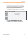
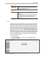
To upload a floppy image file:
1. From the Main Menu, select Virtual Media Æ Floppy Disk to open the Floppy
Image Upload window.
2. Click Browse to locate the floppy image file.
SecureLinx Spider User Guide
31
6: Virtual Media
3. Click Upload to load the image into Spider’s memory. This floppy drive is accessible
to the remote computer as a letter-name floppy drive (e.g. B:).
4. To remove the current image file, click Discard.
CD-ROM Image
The Virtual Media-CD-ROM Image option allows the Spider to access a CD-ROM image
up to 800 MB on a Windows shared folder via SAMBA. The Spider then makes that
image accessible to the target computer by emulating a USB disk drive.
Appropriate administrative permissions to access the host and file are needed, as well as
the ability to see that computer over the network from the Spider.
The connection remains mounted until the current user logs out or the Spider is rebooted.
Other client systems logging into the Spider will see the active image in all Virtual Media
pages.
To access a CD-ROM image:
1. From the Main Menu, select Virtual Media ÆCD-ROM Image to open the Image on
Windows Share page.
2. Enter the Share host name, Share name, and Path to image
3. If the file is protected, enter the User name and Password.
4. Click Set to mount the image. (The file must be structured as a CD-ROM image.) The
filename appears as the Active Image and the image is available to the target
computer as a letter drive (e.g. F:).
5. Click Discard to terminate the connection to the share drive.
SecureLinx Spider User Guide
32
6: Virtual Media
Drive Redirection
Drive Redirection allows you to share (redirect) your local drive (floppy drives, hard
disks, CD ROMs and other removable devices like USB sticks) with the remote system
over a TCP network connection. Thus, with Drive Redirection, you can use a virtual disk
drive on the remote computer instead of an image file. It is also possible to enable a
r e m o t e machine to write data to your local disc.
Note: Drive Redirection supports only Windows as the client computer since it
redirects based on a drive letter.
To redirect a drive:
1. From the Main Menu, select Virtual Media ÆDrive Redirection.
2. In the Drive Redirection section, select one or both of the following:
Disable Drive Redirection: Drive Redirection is enabled by default. Select this
checkbox to disable the ability to share the local drive with the remote system.
Force read-only connections: Select to prevent the remote drive from writing
to your local drive. Selected by default.
Warning: Clearing the Force read-only connections check box may
result in file system errors and data corruption because of drive caching
when data is written back to the Redirected local drive.
Note: An asterisk to the right of a setting indicates that the setting is the
default.
3. Click Apply to save settings.
To connect to a redirected drive:
If Drive Redirection is enabled, you can connect to the drive. Depending on the
combination of the type of and the Force read-only connections setting, different
warnings display.
1. Click the Console link at the top of the Spider web page or click the console image
that you see when you log in to the Spider. The remote console displays?
SecureLinx Spider User Guide
33
6: Virtual Media
2. Click the disk icon
in the toolbar. The Drive Redirection page displays.
3. Click the Connect Drive button at the top of the page. The Select a drive to redirect
dialog box opens.
4. From the drop-down list, select the drive you want to redirect.
Note: To refresh the list after adding or removing a drive, click the Refresh
List button.
5. If desired, select the Enable Write support check box.
6. Click OK. Depending on your selections, the following events or warnings display:
If you select Enable Write support, the following warning displays:
SecureLinx Spider User Guide
34
6: Virtual Media
Because of the danger of destroying all data on the drive, click Yes only if you
are certain of what you are doing.
If you select the hard disk from the drop-down list, the following warning may
display:
When drive redirection is enabled and a connection is made, the Spider attempts
to lock the locally shared drive. This prevents local access to the drive while it is
being shared with the remote PC. If the drive cannot be locked, and write
capability is enabled, the local computer can be exposed to file corruption if both
the local and remote computers attempt to write to the local drive at the same
time. In general, the Spider cannot lock the boot partition (typically the C: drive)
because locking would prevent the OS from accessing necessary files. We
recommend that you use drive redirection with a non-boot partition or with a
separate physical drive like a second hard drive, external storage device, or
CD/DVD drive.
If you select a drive other than the hard disk, and do not select Enable Write
support, the connection to the redirection of the drive is successful.
SecureLinx Spider User Guide
35
6: Virtual Media
Virtual Media Options
The operating system on the target computer must have a USB mass storage driver
installed in order to use Virtual Media. As the BIOS on some systems does not always
support mass storage emulation on the USB interface, the system default is to disable
USB mass storage unless an image is loaded. This option may be unselected to use
virtual media options. Only one active virtual media image is available at a time.
To configure virtual media options:
1. From the Main Menu, select Virtual Media Æ Options to open the Virtual Media
Options window.
2. Select or deselect Disable USB Mass Storage if no image is loaded.
3. Click Apply to save settings. Click Reset to Def to restore the system default.
SecureLinx Spider User Guide
36
7: User Management
Local vs. Remote Authentication
User names and groups may be administered on the Spider to allow varying levels of
access and control to different classes of users. In order to log in to the Spider, a user
must be authenticated by means of a password. This authentication may take place
locally, where the user name and associated password are stored in the Spider’s
memory. The Spider may query a centralized database using RADIUS or LDAP to
determine if a given user may log in. In both of these cases, the user name must be
defined on the Spider where it has its permissions assigned.
Local User Management
On a Spider, each user name has associated with it settings and permissions. Settings
affect how the user interfaces with the Remote Console. Permissions allow or forbid the
user from performing various actions on the Spider’s web pages. A newly assigned user
has permissions inherited from an assigned group, if any, or individual permissions if no
group is assigned.
Modifying Passwords
To change current user password:
1. Select User ManagementÆChange Password from the Main Menu. The Change
Password screen displays.
2. Enter the current password under Old Password.
SecureLinx Spider User Guide
37
7: User Management
3. Enter the new password under New Password and Confirm New Password.
4. Click Apply to save your settings.
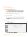
User and Group Management
You must be logged in under a user name that has permissions for User/Group
Management in order to access this page. The Spider supports a maximum of 50
configured users.
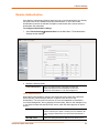
To configure users and groups:
1. Select User ManagementÆUsers from the Main Menu. The User Management
page displays.
2. Configure the following fields:
User Management
Existing users
To modify or copy an existing user, select that user from the
drop-down menu and click Lookup.
New user name
Enter the new user’s name. Minimum 1 character.
Full user name
Enter the full name of the configured user. Minimum 1
character.
Password
Enter the password for the user. Minimum 4 characters.
Confirm Password
Re-enter the password for the user.
Email address
(Optional) Enter the user’s email address.
Mobile number
(Optional) Enter the user’s mobile phone number.
Group Membership
Select the user’s group from the pull-down menu.
Enforce user to change
password on next login
Select checkbox to require the user to change their password
upon initial login.
SecureLinx Spider User Guide
38
7: User Management
3. Click Create to add the new user. Click Modify to change an existing user. Click
Copy to create a new user based on the selected existing user. Click Delete to
delete an existing user.
4. Configure the following fields:
Group Management
Existing Groups
To copy or modify a group, select the group from the pulldown menu. Click Lookup.
New Group Name
Enter the new group’s name.
5. Click Create to add the new group. Click Modify to change an existing group. Click
Copy to create a new group based on the selected existing group. Click Delete to
delete an existing group.
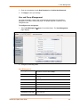
User Permissions
To modify user permissions:
1. Select User ManagementÆPermissions from the Main Menu. The User/Group
Permissions window displays.
2. From the pull-down menu, select a User or Group to configure.
3. Modify the displayed permissions as necessary for the selection.
4. Click Update to save the permission changes.
SecureLinx Spider User Guide
39
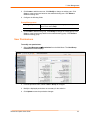
8: KVM Settings
User Console
The Remote Console window into the target system has settings that may be changed for
the way each individual user interacts with the Spider. When a user is created by copying
from an existing user, the Remote Console settings will be copied as well. These settings
may be changed on the page KVM Settings Æ User Console. Note that if you are using
the Spider View application, these settings do not apply; see the Spider View User Guide
for further information.
The way in which the Spider transmits video data back to the client system can be
tailored for the type of network connection. On a LAN where bandwidth is not an issue,
compression is not required and the speed of updates can be maximized. For other
connections, the optimum user interaction needs to trade off image quality and update
speed to fit the size of the pipe. Because various users may be accessing the Spider over
different connections, these parameters are applied on a user-by-user basis. The default
is set for maximum image quality and speed of updates, which results in high data rate
and hence is suitable for LANs where bursts of up to 2 Mbytes/second are acceptable.
To modify the user console:
1. Select KVM SettingsÆUser Console from the Main Menu. The Remote Console
Settings for User window displays.
SecureLinx Spider User Guide
40
8: KVM Settings
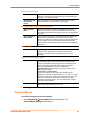
2. Configure the following settings:
Remote Console Settings for User
<User pull-down
menu>
Select the user from the pull-down menu. The settings on this page
apply only to the selected user. When a user is created by copying
from an existing user, the Remote Console settings will be copied
as well. Click the Update button.
Transmission Encoding
Automatic
Detection
This option uses an algorithm to try to determine what sort of
connection is being used, and sets up parameters to match. These
settings may change from login to login depending on the state of
the network at that point.
Preconfigured
Establishes a set of parameters optimized for each of a number of
connection types. The default transmission encoding is LAN (high
color), which is uncompressed with a 16 bit color depth. Other data
networks may be chosen from the list, and the compression and
color depth will be configured accordingly.
Manual
Allows the direct control of the compression factor and color depth.
The simplest way to reduce bandwidth is to cut the color depth
down to 8 bits; subtle color shades will be gone but the overall
image is very usable. Dialing up the compression level also makes
available even further reductions in color depth, all the way down to
black and white (1 bit.) As compression level increases and/or color
depth decreases, image quality and responsiveness to changes
deteriorates but required bandwidth is reduced
SecureLinx Spider User Guide
41
8: KVM Settings
Remote Console Type
Default Java VM
Select this option to use Java on the client system launching the
applet. If no Java environment is installed, the console window will
not launch. The default is enabled.
Sun Microsystems
Java Browser
Plugin
Force the system to use the platform-independent Sun version
instead when launching the Remote Console applet.
Miscellaneous Remote Console Settings
Start in Monitor
Mode
Results in the Remote Console window being view-only when
launched for this user. This may be changed to interactive mode
from within the Remote Console window, if the user has appropriate
permission.
Start in Exclusive
Access Mode
Upon any subsequent launch of the Remote Console applet by the
selected user, terminates any other users’ Remote Console
windows and locks out any other users trying to access the Remote
Console window. This may be changed from within the Remote
Console window to allow shared access, if the user has appropriate
permission.
Mouse Hotkey
Hotkey
When the Remote Console window is open, a key code that is not
captured by the client system is needed for certain mouse
functions. The default is Alt+F12. Change the he key code if
necessary.
Remote Console Button Keys
Key Definition
Button Keys allow simulating keystrokes at the remote system that
cannot be generated from the client keyboard. A flexible syntax
allows for combinations of keys being clicked in combination or in
sequence, with optional pauses and an optional confirmationbefore-sending dialog box. One key is predefined, for
Ctrl+Alt+Delete (with confirmation.) The syntax to define a new
Button Key is as follows:
<keycode>[+|-|>[*]<keycode>]*
Keycode is the key to be sent (see onscreen Help for a list).
Multiple key codes are concatenated with a + or a - sign. The + sign
builds key combinations, all keys will be clicked until a - sign or the
end of the combination is encountered. All clicked keys will be
released in reversed sequence. The - sign builds single, separate
key clicks and key releases.
Name
Appear on the button in the Remote Console window. Up to nine
Button Keys may be defined for each user
3. Click Apply to save changes. Click Reset to Def to reset values back to default.
Keyboard/Mouse
To modify the keyboard and mouse settings:
1. Select KVM SettingsÆKeyboard/Mouse from the Main Menu. The
Keyboard/Mouse Settings window displays.
SecureLinx Spider User Guide
42
8: KVM Settings
2. Modify the following fields:
Host Interface
Host Interface
In general, the USB interface is preferred because it provides
superior mouse tracking. The Host Interface pull-down provides for
three selections. In the default mode, Auto, the Spider will attempt
to determine if the attached computer supports a USB
keyboard/mouse. If it does, that interface will be activated, but if it
does not the Spider will fall back to PS/2. If you have a USB model
Spider and the attached computer does not support USB, you will
have a view-only system. On the PS/2 model Spider, select PS/2 to
force the PS/2 interface or USB to require USB. This selection has
no effect on the USB model Spider
Force USB Full
Speed Mode
Some older systems do not support USB high-speed mode and
may not recognize the keyboard/mouse. Enable this option for
Spider to negotiate in USB full speed mode.
PS/2 Keyboard Model
<PS/2 keyboard
model pull-down
menu>
When operating in PS/2 interface mode, key codes from several
layouts may be emulated.
Generic 104-key PC for the traditional layout
Generic 109-key PC for keyboard with added Windows keys
(Use 109 for Japanese keyboard)
Apple Macintosh for Mac layout
SUN Type 6 for Sun Solaris layout
Key Release Timeout
Key release timeout
Network delays may sometimes result in duplicated keystrokes.
Enable Key Release Timeout to fix this problem.
Timeout after
Enter time, in msec.
SecureLinx Spider User Guide
43
8: KVM Settings
USB Mouse Type
<USB mouse type
pull-down menu>
Different operating systems running on the target system require
different mouse emulation protocols. One selection is available for
newer versions of Windows and Mac OS/X, and another for Other
Operating Systems (e.g., Linux).
Mouse Speed
Mouse speed
Auto mouse speed determines the speed and acceleration settings
of the target system. It is the recommended setting for most
applications.
Fixed scaling translates a one-pixel motion on the client system to
a selectable number of pixels moved on the target system. As the 1
to n mapping is linear, this will only work when there is no
compression acceleration or other special effects turned on at the
target system.
3. Click Apply to save settings. Click Reset to Def to restore values to system defaults.
Video
The Spider works by capturing and digitizing the analog video coming from the attached
computer. This analog video may have more or less low-level electrical noise present,
depending on the nature of the video card or embedded video controller. When viewed
on a monitor, this noise (if random) is invisible as the display is being redrawn 60 to 100
times a second. Inside the Spider, however, the algorithm sees that noise as something
changing on the screen, so that requires sending off an update to the client system. This
can result in a constant stream of data even when the image on the target computer’s
screen is not moving. In order to avoid this, at KVM Settings Æ Video Æ Miscellaneous
Video Settings the Spider has a selection for Noise Filter. The larger filter openings will
filter out more of the noise, at the cost of potentially missing small incremental changes
and seeing some compression artifacts (blocky-ness.) Filter settings of Normal or Large
will work for most applications. Be sure to try the Remote Console Auto Adjust Video
button a few times before deciding that a constant stream of data represents electrical
noise requiring a larger filter setting.
To modify video settings:
1. Select KVM SettingsÆVideo from the Main Menu. The Miscellaneous Video
Setting window displays.
SecureLinx Spider User Guide
44
8: KVM Settings
2. Select the Noise Filter level from the drop-down menu.
3. Click Apply to save settings. Click Reset to Def to restore system defaults.
.
SecureLinx Spider User Guide
45
9: Device Settings
Network Settings
Network settings may be found on the web page Device Settings Æ Network. As you are
already talking to the Spider over a network, do not forget that changing the settings may
result in dropping the connection. This will happen at the point that you click the Apply
button. Take particular care to ensure your new settings are correct when making
changes from a remote site!
To modify network settings:
1. Select Device SettingsÆNetwork from the Main Menu. The Network window
displays.
2. Modify the following fields:
Basic Network Settings
IP auto
configuration
Select DHCP or BOOTP to fetch network settings from the
appropriate type of server. Select NONE for a fixed IP address.
Preferred Host
Name (DHCP only)
DHCP servers can register a name for this Spider to assist in
finding it.
IP address
If you are using a fixed IP address, enter it in the usual dot notation.
Subnet Mask
If you are using a fixed IP address, enter the subnet mask of the
local network.
SecureLinx Spider User Guide
46
9: Device Settings
Gateway IP address
(optional)
If the Spider to be accessible from outside the local subnet, enter
the IP address of the router providing access.
Primary DNS
Server IP Address
(optional)
For name resolution, enter the IP address of the primary Domain
Name Server. This is optional, but needed if names rather than
static IP addresses are used for certain Spider functions requiring
network connections.
Secondary DNS
Server IP Address
(optional)
Enter the IP address of the Domain Name Server to be used if the
Primary DNS Server cannot be reached.
Miscellaneous Network Settings
Remote Console
and HTTPS port
Port number at which the Spider’s Remote Console server and
HTTPS server are listening. The default is 443.
HTTP port
Port number at which the Spider’s HTTP server is listening. The
default is 80.
Telnet port
Port number at which the Spider’s Telnet server is listening. The
default is 23.
SSH port
Port number at which the Spider’s SSH server is listening. The
default is 22.
Bandwidth Limit
The maximum network traffic generated through the Spider’s
primary Ethernet port, in kilobits. If left blank, there is no bandwidth
limitation applied.
Enable Telnet/SSH
access
For security, the default is having Telnet and SSH disabled. Check
the appropriate box(es) and set up the serial port for Telnet/SSH to
use the Telnet console.
Disable Setup
Protocol
Spider View uses a special protocol to locate and set up Spider IP
addresses. As a security measure you may wish to disable this
protocol when Spiders are deployed.
LAN Interface Settings
LAN interface
speed
Manual setup may be required for older equipment. With
autonegotiation on, the window displays the current state of the link.
Note that the parameters of the second Ethernet port are not
configurable, they remain at autonegotiate. Select the speed from
the pull-down menu.
LAN interface
duplex mode
Select the duplex mode from the pull-down menu.
3. Click Apply to save settings. Click Reset to Def to restore system defaults.
Security
General settings for security parameters such as encryption and access control may be
found at Device Settings Æ Security. Other areas with security implications include
User Management/Permissions, Authentication, Network Settings, and the Event Log;
see the appropriate sections for information on those areas.
SecureLinx Spider User Guide
47
9: Device Settings
To modify security settings:
1. Select Device SettingsÆSecurity from the Main Menu. The Security window
displays.
2. Modify the following fields:
HTTP Encryption
Force HTTPS for
Web Access
Typically, the Spider listens on both HTTP and HTTPS ports for
incoming connections. If this box is checked, access can only be
made using SSL, and connection requests on the HTTP port will be
ignored. See the section on Certificate for further information on
how the Spider identifies itself using a cryptographic certificate.
KVM Encryption
KVM Encryption
In addition to the SSL encryption of the Spider’s web pages, the
keyboard, mouse, and video data may be encrypted. Select Off to
use no encryption.
Select Try for the Spider to attempt to make an encrypted
connection but will back off to unencrypted if one cannot be
established.
Select Force for an encrypted connection to be made or an error
will be reported.
Group Based Access Control
Enable Group
Based System
Access
When this box is checked, the rules for IP based access are
enforced. They are ignored when the box is not checked.
Default Action
If after evaluation of all rules a request for connection from a given
IP address has not had either an Accept or Drop decision made,
SecureLinx Spider User Guide
48
9: Device Settings
this selection can allow it to be either Accepted or Dropped. In other
words, this pull-down defines the default action for IP addresses
with no rules defined.
Rule creation and
editing
Spiders come from the factory with one rule defined as an example
of the rule structure: Rule 1 allows all groups access from source IP
0.0.0.0 to 255.255.255.255. Additional rules may be entered in the
edit boxes. The Rule Number defines where in the evaluation
sequence this rule is to be applied. The Starting and Ending IP
Addresses define the range over which the rule applies. The
Group defines which user group is affected by this rule. Built-in
groups include Admin, All, and Unknown (no group assigned.) As
additional groups are defined in User Management Æ Users Æ
Group Management, these will appear in the pull-down. A rule can
apply to only one group at a time. The Action selection chooses
whether this is to be a Drop or Accept rule.
After a rule has been defined, it needs to be put in the correct place
in the list. Append will put the rule at the end of the list. The rule
number will be changed to reflect the last position on the list. Insert
will put the rule in the place on the list indicated by the rule number,
renumbering and moving down the other rules to make room.
Replace deletes the previous rule of that number, and replaces it
with the new rule. Delete deletes the rule of that number, and
moves the others up. Note that for a Delete the fields other than the
rule number do not need to be filled in.
Login Limitations
Enable Single
Login Limitation
If this box is checked, each username may only have one logged in
connection at a time. If unchecked, multiple instances of username
logins are allowed.
Screenshot Access
Enable
Screenshot
Access without
Authentication
Select this option when you need to access the snapshot image
without logging in to the Spider. If enabled, the screenshot can be
read directly with http(s)://<spiderIPaddress>/screenshot.jpg. One
use of this unauthenticated screenshot is to read it from a Google
gadget
3. Click Apply to save settings. Click Reset to Def to restore system defaults.
Certificate
The Spider uses the Secure Socket Layer (SSL) protocol for any encrypted network
traffic between itself and a connected client. During the connection establishment the
Spider has to expose its identity to a client using a cryptographic certificate. Upon leaving
the factory this certificate and the underlying secret key is the same for all Spiders and
will not match the network configuration where it is installed. The certificate’s underlying
secret key is also used for securing the SSL handshake. Leaving the default certificate
unmodified is all right in most circumstances and is necessary only if the network facility
is deemed vulnerable to man-in-the-middle attack.
It is possible to generate and install a new base64 x.509 certificate that is unique for a
particular Spider. The Spider is able to generate a new cryptographic key and the
associated Certificate Signing Request (CSR) that needs to be certified by a certification
authority (CA).
SecureLinx Spider User Guide
49
9: Device Settings
To create and install an SSL certificate:
1. Select Device SettingsÆCertificate from the Main Menu. The Certificate Signing
Request window displays.
2. Modify the following fields:
Common Name
The network name of the Spider once it is installed in the user’s
network (usually the fully qualified domain name). It is identical to
the name that is used to access the Spider with a web browser
without the prefix http://. In case the name given here and the
actual network name differ, the browser will pop up a security
warning when the Spider is accessed using HTTPS.
Organizational Unit
This field specifies to the department within an organization to
which the Spider belongs.
Organization
The name of the organization to which the Spider belongs.
Locality/City
The city where the organization is located.
State/Province
The state or province where the organization is located.
Country (ISO code)
The country where the organization is located. This is the two-letter
ISO code (e.g. US for the United States).
Email
The email address of a contact person responsible for the Spider
and its security.
Challenge
password
Certain certification authorities require a challenge password to
authorize later changes on the certificate (e.g. revocation of the
certificate). The minimal length of this password is four characters.
Confirm Challenge
password
Re-enter password.
Key length (bits)
Select the key length from the pull-down menu.
SecureLinx Spider User Guide
50
9: Device Settings
3. Click Create to initiate the Certificate Signing Request generation. Download the
CSR by clicking Download. The Download button displays when a certificate is
created. Send the saved CSR to a CA for certification.
4. Click Upload to upload the certificate from the client computer to the Spider. The
Spider now has its own certificate used for identifying itself to its clients.
Serial Port
After using the serial port to set up the Spider’s network parameters, you may put the
serial port to another use. You may establish A PPP connection to use a modem or other
serial connection to log in to and operate the Spider. If you want to use the serial port to
tunnel through to the network side of the Spider, Telnet and/or SSH connections are
available.
To configure the serial port:
1. Select Device SettingsÆSerial Port from the Main Menu. The Serial Port Settings
window displays.
2. Modify the following fields:
Configuration
Login
Select this option to use the serial port locally only to set up network
parameters or reset the unit.
Modem
Connect to the Spider via a dial-up or ISDN connection, using PPP.
Essentially, the Spider acts as an ISP that you dial in to. The client
system will need to be set up accordingly, for example using the
Windows Network Connection Wizard. Change the following
parameters as necessary:
Serial Line Speed: Most modems support 115200 bps.
Modem Init String: The initialization string sent out to set up the
modem. If you have a special modem or are going through a PBX
requiring an access sequence, you may modify the string. Consult
the modem’s manual on the AT command syntax.
Modem server and client IP addresses: As part of the PPP
SecureLinx Spider User Guide
51
9: Device Settings
handshake, IP addresses are assigned to the Spider and client
system.
Passthrough
Access
The serial port may be used to connect to the target server’s COM
port for integrated access to command line functions or used to
control a serial-interfaced peripheral. Telnet and SSH are network
protocols that enable a tunnel from the client system over the
network to the Spider’s serial port. Once the port is set up, it may
be accessed through the web interface at the Telnet Console
window, or using a Telnet/SSH client to connect directly.
Set the parameters to match connected equipment.
3. Click Apply to save settings. Click Reset to Def to restore system defaults.
Date/Time
The Spider contains an internal real time clock that maintains a basic date and time after
being set. The clock, however, will reset if the unit loses power. If an accurate date and
time are critical, the Spider supports synchronization with Network Time Protocol servers.
Internally, the date and time are only used to timestamp events in the log and for the
inactivity timeout.
To configure the date and time settings:
1. Select Device SettingsÆDate/Time from the Main Menu. The Date/Time Settings
window displays.
2. Modify the following fields:
UTC Offset
Time servers deliver time as Coordinated Universal Time (UTC,
or Greenwich Mean Time). Select the appropriate offset in hours
± from the pull-down menu.
User Specified Time
Manually input the current date and time. The Spider keeps time
as long as power is applied. It has an internal calendar, but does
not know about daylight savings time and requires resetting
SecureLinx Spider User Guide
52
9: Device Settings
twice a year. The internal clock accuracy is ±30 ppm.
Synchronize with NTP
Time Server
Enter a primary and secondary time server in the respective
fields. Ensure NAT and firewalls are set up to allow the protocol
to pass. Also, provide the Spider with DNS server names.
3. Click Apply to save settings. Click Reset to Def to restore system defaults.
SecureLinx Spider User Guide
53
9: Device Settings
Remote Authentication
If the Spider’s Authentication Settings have been set to Local Authentication (the default),
the Spider uses its own database to perform authentication. If one of the remote
authentication protocols is selected, the Spider communicates with a remote server to
authenticate user passwords.
To configure authentication settings:
1. Select Device SettingsÆAuthentication from the Main Menu. The Authentication
Settings window displays.
2. Modify the following fields:
Local Authentication
When Local Authentication is selected, the Spider will
authenticate against its internal database of users and
passwords, as described in Local User Management.
LDAP Authentication
When LDAP Authentication is selected, the Spider will communicate with a Microsoft
Active Directory, Novell Directory Service, or generic LDAP server for user
authentication. The user profile must be set up in the local database as described in
Local User Management, but no password is stored locally. When a user attempts to log
in, the Spider contacts the specified LDAP server, which will either approves or denies
access.
User LDAP Server
Enter the name or IP address of the LDAP server, reachable
over the network by the Spider, containing the user database. Be
sure to configure a DNS server if a name rather that address is
used.
Base DN of User
Specify the Distinguished Name (DN) where the directory tree
SecureLinx Spider User Guide
54
9: Device Settings
LDAP Server
starts in the user LDAP server.
Type of external LDAP
Server
Sets the type of the external LDAP server. Available selections
are Generic LDAP, Novell Directory Service, and Microsoft
Active Directory. If a Generic LDAP Server is selected, edit the
LDAP scheme.
User search subfilter
Restrict the search for users.
Active Directory
Domain
This option represents the active directory domain that is
configured in the Microsoft Active Directory server. This option is
only valid if Microsoft Active Directory is the LDAP server type.
RADIUS
When RADIUS is selected, the Spider communicates with a RADIUS server for user
authentication. To access a Spider set up for RADIUS, log in with a name and password.
The Spider contacts the RADIUS server for authentication and, if approved, the Spider
uses the locally stored user profile. If there is no such profile access via RADIUS will be
refused. The RADIUS implementation also has a timeout whereby if there is no activity
for half an hour the connection to the Spider will be terminated.
Server
Enter the name or IP address of the RADIUS server, reachable
over the network by the Spider, containing the user database.
Configure a DNS server if a name rather than an address is
used.
Shared Secret
A shared secret is a text string that serves as a password
between the RADIUS client and RADIUS server. In this case the
Spider acts as a RADIUS client. A shared secret is used to verify
that RADIUS messages are sent by a RADIUS-enabled device
that is configured with the same shared secret and to verify that
the RADIUS message has not been modified in transit (message
integrity).
Enter a maximum of 128 alphanumeric characters and symbols
such as an exclamation point (“!”) or an asterisk (“*”).
Authentication Port
The port the RADIUS server listens for authentication requests.
The default value is 1812.
Accounting Port
The port the RADIUS server listens for accounting requests. The
default value is 1813.
Timeout
Sets the request time-to-live in seconds. The time-to-live is the
time to wait for the completion of the authentication request. If
the request job is not completed within this interval of time it is
cancelled. The default value is 1 second.
Retries
Sets the number of retries if a request could not be completed.
The default value is 3 times.
3. Click Apply to save settings. Click Reset to Def to restore system defaults.
Event Log
The Event Log maintains a list of significant events locally. Alternatively it can use an
NFS log file, SMTP email, or SNMP to distribute event information on the network. The
Spider monitors five classes of events with the logging of each enabled or disabled.
To configure event log settings:
1. Select Device SettingsÆEvent Log from the Main Menu. The Event Log window
displays.
SecureLinx Spider User Guide
55
9: Device Settings
2. Modify the following fields:
Event Log Targets
List logging enabled
Check this box to use the internal log list of the Spider. The
maximum number of entries is 1,000. Every entry that exceeds
this limit overrides the oldest one. The number of log entries
shown on each page may be changed in the text box. The
internal log list is cleared when power is removed from the
Spider, or when the Clear button is clicked.
NFS Logging enabled
The Spider can write log information to a file on an NFS server.
Provide the name of the server, share, and file in the boxes. The
NFS share will be mounted immediately, and an error message
will result if it cannot be found.
SMTP Logging
enabled
With this option the Spider is able to send emails to an address
given by the email address text field in the Event Log Settings.
These emails contain the same description strings as the internal
log file and the mail subject contains the event class. In order to
use this log destination, specify an SMTP Server, the Receiving
Email Address, and Sender Email Address. Enter the mail
server and SMTP port as <serverip>:<port>.
SNMP Logging
enabled
If selected, the Spider sends an SNMP trap to a specified
destination IP address every time a log event occurs. Configure
the Destination IP and Community. View the SNMP MIB
implemented in the Spider by clicking on the SLS SNMP MIB
link.
Event Log Assignments
Event Log
Assignments
Select the event classes for monitoring, local logging, and
exportation.
3. Click Apply to save settings. Click Reset to Def to restore system defaults.
SecureLinx Spider User Guide
56
9: Device Settings
SNMP
The Spider has an internal SNMP agent that has various objects accessible in its MIB. It
also can generate traps based on events. The Spider permits enabling or disabling the
SNMP agent, input read and write communities, location information, contact information,
and viewing the MIB.
To configure SNMP settings:
1. Select Device SettingsÆSNMP Settings from the Main Menu. The SNMP Settings
window displays.
2. Modify the following fields:
Enable SNMP Agent
Click the checkbox to enable the Spider SNMP agent.
Read Community
Enter the SNMP read community name. The default is public.
Write Community
Enter the SNMP read/write community name. There is no
default.
System Location
Enter the system location.
System Contact
Enter the contact name for the system.
Click here to view the
SNMP MIB
Click the link to view the SNMP MIB.
3. Click Apply to save settings. Click Reset to Def to restore system defaults.
SecureLinx Spider User Guide
57
10: Maintenance
Device Information
The Device Maintenance page contains a table with various pieces of information about
the Spider’s hardware and firmware. This information is useful if technical support is
required.
To view device information:
1. Select MaintenanceÆDevice Information from the Main Menu. The Device
Information window displays.
2. Connected Users displays the IP address of all connected users, and their level of
activity. It also shows whether the user is connected to the Remote Console, and if
so, whether exclusive access mode is activated.
3. System Identifier displays whether a Spider’s LED is lit. Each Spider has an orange
LED that can be lit by remote control, making it easier to locate. By default the LED is
off, but you can uncheck the box to turn on the LED on the Spider you are connected
to.
4. Click Apply.
SecureLinx Spider User Guide
58
10: Maintenance
Event Log
To view the current event log:
1. Select MaintenanceÆEvent Log from the Main Menu. The Event Log window
displays.
2. Navigate between logs by clicking Prev and Next.
Configuration
To update the configuration:
1. Select MaintenanceÆConfiguration from the Main Menu. The Configuration
window displays.
SecureLinx Spider User Guide
59
10: Maintenance
2. Select one of the following options:
Configuration Backup
To back up all settings to a file on the client system, click the
Browse button. The default file name is config_export.gz, but
you may save it using any name. This is the file uploaded to the
Spider upon system restore.
Configuration Restore
To return the Spider settings to a previously saved configuration,
browse to select the configuration file.
Import Configuration File: Browse to and select the backed up
configuration file.
Preserve Basic Network Settings: Select this check box to
preserve the current network basic settings on the Device
SettingsÆNetwork page and import only the remaining settings
from the configuration file.
Click the Upload/Restore button. If you select this option, the
Spider reboots after you apply the update.
Factory Default
To restore factory settings, click the Restore button. The SLM
reboots after you apply the update.
To keep basic network settings rather than restoring defaults,
select the Preserve Network Settings option in the
Configuration Restore area.
SecureLinx Spider User Guide
60
11: Firmware Updates and Resets
Update Firmware
Many of the functions and features of the Spider are implemented in firmware and
capable of field upgrades. The latest firmware may be found at www.lantronix.com. The
firmware file, when uncompressed, is approximately 4Mbytes in size and has a .bin suffix.
Upon updating firmware, the Spider resets itself. After the reset, the login page displays
(if not, manually return to the login page)
To update Spider firmware:
1. Download the firmware file to the client system’s local drive or an accessible network
drive.
2. From the Main Menu, select MaintenanceÆUpdate Firmware. The Firmware
Upload page displays.
3. Click Browse. In the pop-up window, navigate and locate the firmware file.
4. Click Upload to copy the file into the Spider’s local memory. When uploaded
correctly, the Firmware Upload window displays the version number of the new
firmware. Click Update to replace the old with the new. Do not interrupt power to the
Spider during the update process.
SecureLinx Spider User Guide
61
11: Firmware Updates and Resets
Reset
In general, the Spider requires a reset when implementing a firmware update. In the
event In the event of an abnormal operation, a number of subsystems may be reset
without resetting the entire Spider.
To reset the Spider:
1. Log into the Spider as sysadmin.
2. From the Main Menu, select MaintenanceÆUnit Reset. The Unit Reset page
displays.
3. Click Reset for Keyboard/Mouse, USB, or Video Engine button to clear and reset the
subsystem. Resetting subsystems does not terminate connected users.
4. To perform a complete reset, click Reset for Reset Device. A prompt displays,
requesting confirmation. A complete reset closes all user connections and performs a
full reboot.
SecureLinx Spider User Guide
62
12: Command Line Interface (CLI)
Introduction to Commands
Command Syntax
Commands have the following format:
<action> <category> <parameter(s)>
where
<action> is set, show, connect, diag, admin, or logout.
<category> is a group of related parameters you want to configure or view. Examples
are devicegroup, account, and network.
<parameter(s)> is one or more name-value pairs in one of the following formats:
<parameter name> <aa⏐bb>
Specify one of the values (aa or bb)
separated by a vertical line ( | ). The
values are all lowercase and must be
entered exactly as shown. Bold indicates
a default value.
<parameter name> <Value>
Specify an appropriate value, for
example, a device group name.
Square brackets [ ]
This User Guide shows parameter values
in mixed case to indicate they are case
sensitive. For example, if you saved a
device group name in mixed case, you
must enter it in mixed case; if you saved it
in lowercase, you must enter it in
lowercase.
Indicate optional parameters.
Figure 12-1. Actions and Category Options
Action
set
show
connect
admin
logout
Category
sshkey|history
sshkey|history
serial
version | config
Terminates CLI session.
SecureLinx Spider User Guide
63
12: Command Line Interface (CLI)
Command Help
For general command help, type: help
For more information about a specific command, type help followed by the command,
for example:
help set network
OR
type ? after the command:
set network ?
Tips
Type enough characters to identify the action, category, or parameter name
uniquely. For parameter values, type the entire value. For example,
set network port 1 state static ipaddr 122.3.10.1 mask
255.255.0.0
can be shortened to:
se net po 1 st static ip 122.3.10.1 ma 255.255.0.0
Use the Tab key to automatically complete action, category, or parameter
names. Type a partial name and press Tab to complete the name if only one is
possible, or to display the possible names if more than one is possible.
Should you make a mistake while typing, backspace by pressing the Backspace
key or the Delete key, depending on how you accessed the interface. Both keys
work if you use VT100 emulation in your terminal access program when
connecting to the console port. Use the left and right arrow keys to move within
a command.
Use the up and down arrows to scroll through previously entered commands. If
desired, select one and edit it. You can scroll through up to 100 previous
commands entered in the session.
When the number of lines displayed by a command exceeds the size of the
window (the default is 20), the "Type more to see the next page"
message displays. To display the next page, type more and press Enter.
You can override the number of lines (or disable the feature altogether) with the
set cli command.
To clear an IP address, type 0.0.0.0.
SecureLinx Spider User Guide
64
12: Command Line Interface (CLI)
Configuration Commands
admin config
Syntax
admin config factorydefaults
Description
Restores the SLS configuration and device database settings to factory defaults.
Note: The unit will reboot after this command. All current settings will be lost.
Connect Commands
connect serial
Syntax
connect serial
Description
Connects the Spider to a device's serial port.
Note: In order to connect to a serial port, put the serial port in passthrough mode
on the web interface. See Serial Port section on page 51.
ESC exit
Syntax
ESC exit
Description
Exits a serial port connection.
SSH Key Commands
set sshkey delete
Syntax
set sshkey delete keyuser <SSH Key User> keyhost <SSH Key Host>
Description
Deletes an imported SSH key.
SecureLinx Spider User Guide
65
12: Command Line Interface (CLI)
Example
set sshkey delete keyuser sysadmin keyhost slm-pipe
Deletes imported SSH public key on host slm-pipe for the user sysadmin.
set sshkey import
Syntax
set sshkey import <copypaste>
Imports public SSH key (OpenSSH format)
Note: RSA keys must be 1024 bits
set sshkey import <copypaste> format <openssl> keyuser <SSH Key User>
keyhost <SSH Key Host>
Imports public SSH key (OpenSSL format)
Description
Imports an SSH key.
Example
set sshkey import copypaste format openssl keyuser sysadmin keyhost
slm-pipe
Imports public key in OpenSSL format on host slm-pipe for the user sysadmin.
show sshkey import
Syntax
show sshkey import <one or more parameters>
Parameters
[keyuser <SSH Key User>]
[keyhost <SSH Key IP Address or Name>]
[viewkey <enable|disable>]
Description
Displays imported SSH keys.
Examples
show sshkey viewkey enable
Displays all imported SSH public keys with content of keys.
show sshkey keyuser sysadmin keyhost slm-pipe
Displays imported SSH public key on host slm-pipe for the user sysadmin.
SecureLinx Spider User Guide
66
12: Command Line Interface (CLI)
History Commands
set history clear
Syntax
set history clear
Description
Clears the CLI command history.
show history
Syntax
show history
Description
Displays the 100 most recent CLI commands.
Version Command
admin version
Syntax
admin version
Description
Displays Spider firmware version information.
SecureLinx Spider User Guide
67
12: Command Line Interface (CLI)
A: Troubleshooting
1. No connection can be established to the Spider
Check cabling. Are both USB cables or all of the USB and PS/2 cables plugged in?
Are both Pwr LEDs lit? Is the Ethernet cable plugged in, and the Link light lit? Is there
Activity?
Have a look on your network. Verify your network configuration (IP address, router).
Send a ping request to the Spider to find out whether the Spider is reachable via the
network. Establish a direct connection between the Spider and the client. If you use a
firewall then check the appropriate port for accepting connections. The TCP ports 80
(for HTTP) and 443 (for both HTTPS and RFB) have to be open (the server providing
the firewall has to accept incoming TCP connections on these ports). You may
restrict these connections to the IP addresses used by the Spider and your client.
2. Login on the Spider fails.
Verify both your user login and your password. By default, the user sysadmin has
the password PASS. Ensure the web browser is configured to accept cookies.
3. The Remote Console window of the Spider does not open.
A firewall may prevent access to the Remote Console (TCP port 443). If there is a
proxy server between the Spider and your host, then you may not be able to transfer
the video data using RFB. Check the settings of the Spider and choose a different
server port used for RFB transfer. A Java Runtime Environment may not be installed,
or may be disabled.
4. The video quality is bad or the picture is grainy.
Enter the Remote Console and click the Auto Adjust button to adjust the Spider’s
video input parameters to the correct values.
5. Special key combinations (e.g. ALT+F2, ALT+F3) are intercepted by the client
system and not transmitted to the remote computer.
You have to define a Button Key. This can be done in the Remote Console settings.
Alternatively, use the soft keyboard feature.
6. The Spider web pages are not displayed correctly.
Check your browser’s cache settings. Ensure the cache settings are not set to “do
not check for newer pages." Otherwise the web pages may be loaded from your
browser cache and not from the Spider.
7. Every time I open a dialog box with some buttons the mouse pointers are not
synchronous anymore.
Disable the setting Automatically move mouse pointer to the default button of
dialog boxes in the mouse settings of your operating system.
SecureLinx Spider User Guide
68
12: Command Line Interface (CLI)
8. The Remote Console does not open with Opera in Linux.
Some versions of Opera do not grant enough permission if the signature of the applet
cannot be verified. To solve the problem, add the lines grantcodeBase
"nn.pp.rc.RemoteConsoleApplet" { permission java.lang.RuntimePermission
"accessClassInPackage.sun.*"; to the java policy file of opera (e.g.
/usr/share/opera/java/opera.policy).
9. I forgot my password. How can I reset the Spider to factory defaults?
Use the serial interface with a terminal emulator program. Within 2 seconds of
booting the Spider, enter the Esc key a few times to get a Î prompt. Enter Defaults.
10. Cannot upload the signed SSL certificate in MacOS X.
If an “internal error” occurs while uploading the signed certificate either changes the
extension of the file to .txt or adds a file helper using the Internet Explorer
preferences for this type of file. Make sure that the encoding is set to “plain text” and
the checkbox “use for outgoing” is set. As an alternative, you may also use a Mozilla
based browser (Mozilla, FireFox).
SecureLinx Spider User Guide
69
B: Supported Video Formats
The following table displays supported video formats for the Spider:
Resolution (x,y)
640x340
640x400
640x480
720x400
800x600
832x624
1024x768
1152x864
1152x870
1152x900
1280x960
1280x1024
SecureLinx Spider User Guide
Refresh Rates (Hz)
70, 85
56, 85
60, 67, 72, 75, 85
70, 85
56, 60, 70, 72, 75, 85
75
60, 70, 72, 75, 85
75
75
66, 76
60
60
70
C: Technical Support
If you are unable to resolve an issue using the information in this documentation:
Technical Support US
Check our online knowledge base or send a question to Technical Support at
http://www.lantronix.com/support.
Technical Support Europe, Middle East, Africa
Phone: +33 1 39 30 41 72
Email: mailto:[email protected] or mailto:[email protected]
Firmware downloads, FAQs, and the most up-to-date documentation are available at
http://www.lantronix.com/support
When you report a problem, please provide the following information:
Your name, and your company name, address, and phone number
Lantronix model number
Lantronix serial number
Firmware version
Description of the problem
Target computer interface (PS/2 or USB) and video format
Status of the unit when the problem occurred (please try to include information on user
and network activity at the time of the problem)
SecureLinx Spider User Guide
71
D: Compliance
(according to ISO/IEC Guide 22 and EN 45014)
Manufacturer’s Name & Address:
Lantronix Inc., 15353 Barranca Parkway, Irvine, CA 92618 USA
Declares that the following product:
Product Name(s): SecureLinx Spider
Conform to the following standards or other normative documents:
UL/CUL (CSA-22.2 No. 60950-1-03 / UL-60950-1)
CE - IEC 60950-1
C-Tick
FCC Part 15, Equipment Class A
VCCI V-3/2006.04 Class A
AS/NZS CISPR 22: 2006 Class A
EN55022:1998 +A1:2000 +A2:2003 Class A
EN61000-3-2: 2000 +A2: 2005 Class A
EN61000-3-3: 1995 +A1: 2001
EN55024: 1998 +A1:2001 +A2:2003
Pb-free components
SecureLinx Spider User Guide
72
E: Warranty
Lantronix warrants each Lantronix product to be free from defects in material and
workmanship for a period of TWO YEARS after the date of shipment. During this period,
if a customer is unable to resolve a product problem with Lantronix Technical Support, a
Return Material Authorization (RMA) will be issued. Following receipt of an RMA number,
the customer shall return the product to Lantronix, freight prepaid. Upon verification of
warranty, Lantronix will -- at its option -- repair or replace the product and return it to the
customer freight prepaid. If the product is not under warranty, the customer may have
Lantronix repair the unit on a fee basis or return it. No services are handled at the
customer's site under this warranty. This warranty is voided if the customer uses the
product in an unauthorized or improper way, or in an environment for which it was not
designed.
Lantronix warrants the media containing its software product to be free from defects and
warrants that the software will operate substantially according to Lantronix specifications
for a period of 60 DAYS after the date of shipment. The customer will ship defective
media to Lantronix. Lantronix will ship the replacement media to the customer.
*
*
*
*
In no event will Lantronix be responsible to the user in contract, in tort (including
negligence), strict liability or otherwise for any special, indirect, incidental or
consequential damage or loss of equipment, plant or power system, cost of capital, loss
of profits or revenues, cost of replacement power, additional expenses in the use of
existing software, hardware, equipment or facilities, or claims against the user by its
employees or customers resulting from the use of the information, recommendations,
descriptions and safety notations supplied by Lantronix. Lantronix liability is limited (at its
election) to:
refund of buyer's purchase price for such affected products (without interest)
repair or replacement of such products, provided that the buyer follows the above
procedures.
There are no understandings, agreements, representations or warranties, express or
implied, including warranties of merchantability or fitness for a particular purpose, other
than those specifically set out above or by any existing contract between the parties. Any
such contract states the entire obligation of Lantronix. The contents of this document
shall not become part of or modify any prior or existing agreement, commitment or
relationship.
For details on the Lantronix warranty replacement policy, go to our web site at
www.lantronix.com/support/warranty.
SecureLinx Spider User Guide
73