1
MINUTEMAN
Sentry II
User’s Manual
Table of Contents
INTRODUCTION..................................................................................................................................................................... 4
INSTALLATION....................................................................................................................................................................... 4
SYSTEM REQUIREMENTS ........................................................................................................................................................ 4
INSTALLING THE UPS INTERFACE CABLE ................................................................................................................................ 4
WINDOWS.............................................................................................................................................................................. 5
Install Procedure .............................................................................................................................................................. 5
Starting Sentry II Services ............................................................................................................................................... 5
Connect to Server ............................................................................................................................................................ 6
Uninstall Procedure.......................................................................................................................................................... 7
NOVELL NETWARE ................................................................................................................................................................. 7
Install Procedure .............................................................................................................................................................. 7
Starting Sentry II Services ............................................................................................................................................... 8
Connect to Server ............................................................................................................................................................ 9
Uninstall Procedure.......................................................................................................................................................... 9
UNIX ................................................................................................................................................................................... 10
Install Procedure ............................................................................................................................................................ 10
Starting Sentry II Services ............................................................................................................................................. 11
Connect to Server .......................................................................................................................................................... 12
CONFIGURATION ................................................................................................................................................................ 12
USER MANAGEMENT ............................................................................................................................................................ 13
SERVER SETTINGS ............................................................................................................................................................... 13
UPS CONFIGURATION.......................................................................................................................................................... 14
EVENT CONFIGURATION ................................................................................................................................................... 15
EVENT ACTION .................................................................................................................................................................... 15
Paging ............................................................................................................................................................................ 16
Logging .......................................................................................................................................................................... 17
SNMP Trap .................................................................................................................................................................... 18
Broadcasting .................................................................................................................................................................. 18
Email Notification ........................................................................................................................................................... 19
UPS and/or Operating System Shutdown ..................................................................................................................... 20
Run a System Command............................................................................................................................................... 21
MONITORING ....................................................................................................................................................................... 23
METER ................................................................................................................................................................................ 23
IDENTIFICATION.................................................................................................................................................................... 23
INPUT .................................................................................................................................................................................. 24
OUTPUT .............................................................................................................................................................................. 24
BATTERY ............................................................................................................................................................................. 24
ALARM ................................................................................................................................................................................ 25
VIEW GRAPHIC .................................................................................................................................................................... 25
UPS CONTROL OPTIONS ................................................................................................................................................... 27
CONTROL ............................................................................................................................................................................ 27
SCHEDULING....................................................................................................................................................................... 27
SCHEDULE........................................................................................................................................................................... 27
DATA & EVENT LOGGING .................................................................................................................................................. 28
LOG CONFIGURATION ........................................................................................................................................................... 28
VIEW DATA LOG................................................................................................................................................................... 30
VIEW EVENT LOG ................................................................................................................................................................. 31
-2-
SENTRY II REMOTE ............................................................................................................................................................ 31
SYSTEM REQUIREMENTS ...................................................................................................................................................... 31
WINDOWS CLIENT ................................................................................................................................................................ 32
Installation ...................................................................................................................................................................... 32
Starting Sentry II Services ............................................................................................................................................. 33
NOVELL NETWARE CLIENT ................................................................................................................................................... 33
Installation ...................................................................................................................................................................... 33
Starting Sentry II Services ............................................................................................................................................. 35
UNIX CLIENT ........................................................................................................................................................................ 35
Installation ...................................................................................................................................................................... 35
Starting Sentry II Services ............................................................................................................................................. 37
-3-
INTRODUCTION
Sentry II is a UPS power monitoring application for the Windows 95/98/ME, Windows NT/2000, SCO Unixware/Open
Desktop, HP-UX, IBM AIX, Red Hat Linux, and Novell Netware 4.x, 5.x operating systems. Sentry II monitors the UPS
through a cable attached to a serial port on the computer, and the communications interface on the UPS. This connection
enables Sentry II to check the status of the UPS and to perform a graceful operating system shutdown if required.
Through Sentry II’s web browser interface, you can configure shutdown timers and event actions, view and print event
logs, and view and print power history graphs and data logs.
You can configure Sentry II to perform appropriate actions when an event is detected. The user configurable actions
include: logging, broadcasting, paging, e-mail, command file execution, and UPS and operating system shutdown. You
can set the delays and intervals of these actions. For example, if utility power fails, you may wish to log the event,
broadcast a warning message, page the system administrator, and shutdown the system after a configured time delay.
The monitoring screen displays readings and meters for the UPS. You can customize which values are displayed.
The UPS readings can be logged for later viewing. You can configure the frequency of the data logging. The event log
tracks the history of power and UPS related events. The data log can be viewed, graphed, or printed. The event log can
be viewed or printed.
You can schedule specific actions to occur, such as system shutdown and restarts. You can schedule these actions to
recur one-time, daily, every weekday, or a specific day of the week. Some actions may not be supported on all UPS
models.
INSTALLATION
System Requirements
1. To use Sentry II, your system must be running one of the following operating systems with the TCP/IP protocol:
• Windows 95/98/ME
• Windows NT/2000
• SCO Unixware/Open Desktop
• HP-UX
• IBM AIX
• Red Hat Linux
• Novell Netware 4.x, 5.x
2. Sentry II requires one dedicated RS-232 serial port on your computer, for communications with the UPS.
3. Sentry II requires an additional dedicated RS-232 serial port on your computer, for paging, if this feature is utilized.
Installing the UPS Interface Cable
Install the UPS interface cable by performing the following steps:
1. Locate the UPS interface cable that was provided with Sentry II, or the UPS. (Part # 35000003)
2. Identify the computer end of the cable. The computer end of the cable will have a part # label attached.
3. Plug the connector at the computer end of the cable into the dedicated serial communications port on your computer.
If this end of the cable does not match your serial port connector, use an RS-232 adapter.
4. Plug the connector at the other end of the cable into the interface port on the UPS. (Refer to the UPS user’s manual
for help in locating the interface port.)
NOTE: Sentry II will look for the UPS on com 1 by default. Com ports 2, 3, or 4 maybe used with minor configuration
changes.
-4-
Windows
Install Procedure
Step 1. Insert the Sentry II Installation CD and select Install Software from the menu. If the autorun feature does not
work, run setup.exe located in the {drive}:\\SentryIIServer\Win32 folder on the Sentry II Installation CD.
NOTE: Replace {drive} with the drive letter of the CDROM drive.
NOTE: When using a Windows NT/2000 server, logon as the administrator to ensure that you have full read and write
privileges.
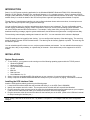
Step 2. The InstallShield Wizard will guide you through the installation process.
Step 3. The default install location is recommended.
Step 4. The default web server port address is 80. If you are running a standard web server such as IIS or Apache, you
may want to change this port address to avoid a conflict.
Starting Sentry II Services
If, at the end of the installation, you selected to start Sentry II, then Sentry II should be running. If not, to start Sentry II,
perform the following steps:
•
Windows 95/98/ME
1. From the Windows Quick Launch Toolbar:
2. Right click on the Sentry II Manager icon.
3. From the popup menu, select Start Sentry II Server.
-5-
NOTE: If the menu reads Stop Sentry II server then the server is already running. By default, the Sentry II Manager is
placed in the windows Startup folder to run at system startup.
•
Windows NT/2000
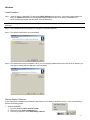
1. Start the Windows Services application.
2. From the Windows Start Menu, select the Settings menu, and then select the Control Panel menu.
3. Select the Administrative Tools folder, and then select the Services application.
4. Locate the Sentry II service in the services list.
5. Right click Sentry II and select Start from the popup menu.
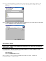
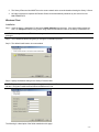
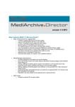
Connect to Server
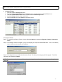
Step 1. To connect to the Sentry II Server, click the Windows Start button and select Programs / Sentry II / Connect to
Server.
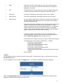
Step 2. The following windows will appear. Sentry II will display your computer’s default DNS name. If not, then manually
enter in either your server name or IP address.
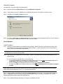
Step 3. Click Connect and your default web browser will start. The Sentry II security page will then appear. The default
User Name and Password is admin.
NOTE: The administrator User Name and Password can be changed from within the Users section once Sentry II is
connected.
-6-
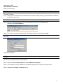
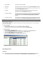
Uninstall Procedure
Uninstall Sentry II by performing the following steps:
Step 1. Open the Windows Control Panel and choose Add/Remove Programs.
Step 2. Choose Sentry II and click Add/Remove. InstallShield will guide you through the uninstall process.
Step 3. InstallShield can Repair or Remove Sentry II.
Step 4. The Sentry II Data Logs and Event Logs are NOT removed during the uninstall process. They can be located in
the C:\Program Files\Minuteman\Sentry II Data and Event folders.
Novell Netware
Install Procedure
Step 1. Sentry II must be installed from a Windows client computer. Before you begin, you will need the name of the
Novell Netware server and where the software will be installed. If you do not know the name of the netware
server, ask your Novell Netware Administrator.
NOTE: Novell Client32 is NOT required, however TCP/IP is a necessity for Sentry II.
The Novell server must be running TCP/IP.
Step 2. Map a drive to the netware server's SYS volume. (NOTE: The netware user must have administrator access
rights for SYS)
If you do not know how to map a drive, see the following:
• For Windows 95/98/ME, from Help on the Windows Start menu, see the index map network drive and To
assign (map) a drive letter to a network computer or folder.
• For NT, from Help on the Windows Start menu, see the index mapping network drives.
• For 2000, from Help on the Windows Start menu, see the index mapping drives and to network computer
or folder.
NOTE: Make a note of the drive letter selected, as this will be needed later. Also the computername is the NetWare
server name and the foldername is SYS. (i.e. \\{computername}\SYS).
Step 3. Insert the Sentry II Installation CD and select Install Software from the menu. If the autorun feature does not
work, run setup.exe located in the {drive}:\\SentryIIServer\Netware folder on the Sentry II Installation CD. NOTE:
Replace {drive} with the drive letter of the CDROM drive.
Step 4. The InstallShield Wizard will guide you through the installation process.
-7-
Step 5. When prompted for the Sentry II installation folder, select the drive letter mapped in Step 2 and enter a new
folder name, a maximum of 8 characters may be used, where the software will be installed. (For example,
F:\SentryII.)
Step 6. The default web server port address is 80. (NOTE: Novell Netware v 5.1 does have the ability to run a web server,
you may want to change this port address to avoid a conflict.)
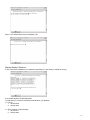
Starting Sentry II Services
NOTE: The hosts file on the Novell server may need to be altered before the Sentry II service can run properly. This can
be done by entering: LOAD EDIT SYS:ETC\HOSTS at the console prompt. The IP address of the server needs to be
referenced to the server name.
From the Novell server, start Sentry II by entering the following commands at the console prompt: (NOTE: replace
InstallFolder with the folder name entered in step 5)
LOAD AIOCOMX.NLM
LOAD NETDB.NLM
LOAD SYS:InstallFolder\SENTRYII.NLM
Sentry II should now be executing on the Novell Netware server. Within a few minutes, you should see
the following messages on the Sentry II display:
-8-
Connecting to UPS...
UPS connected successfully.
Sentry II is now running.
NOTE: To execute Sentry II Server at system startup the support NLM files may be placed in the AUTOEXEC.NCF file.
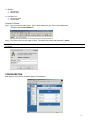
Connect to Server
Step 1. Sentry II must be configured from a Windows client computer. Before you begin, you will need the IP address of
the Novell Netware server.
NOTE: TCP/IP is a requirement for Sentry II. The Windows client must be running TCP/IP.
Step 2. Start your favorite web browser. Type in the IP address of your server in the Address bar.
(Example: http://ServerIPaddress )
Step 3. The Sentry II security web page will load. The default User Name and Password is admin.
NOTE: The administrator User Name and Password can be changed from within the Users section once Sentry II is
connected.
Uninstall Procedure
NOTE: Sentry II uninstall must be executed from the same Windows client computer that performed the original
installation.
Uninstall Sentry II by performing the following steps:
Step 1. Open the Windows Control Panel and choose Add/Remove Programs.
Step 2. Choose Sentry II and click Add/Remove. InstallShield will guide you through the uninstall process.
Step 3. InstallShield can Repair or Remove Sentry II.
-9-
Step 4. The Sentry II Data Logs and Event Logs are NOT removed during the uninstall process. They can be located in
the SYS:InstallFolder\Data and Event folders.
Unix
Install Procedure
Step 1. You must be logged in to the server as root to ensure that you have full read and write privileges.
•
Auto Install: Insert the Sentry II Installation CD into the drive. Mount the CD-ROM drive. Execute the install script
located in the \SentryIIServer\Unix folder on the Sentry II Installation CD.
KNOWN ISSUE: The KDE desktop environment running with the Konqueror web browser does NOT work properly with
install scripts. For this setup, please use the Manual Install listed below.
•
Manual Install: Insert the Sentry II Installation CD into the drive. Mount the CD-ROM drive. Open a terminal
windows and go to the mnt/cdrom/SentryIIServer/Unix folder. Type ./install at the command prompt to begin
the install process.
Step 2. The install script will begin.
Step 3. All default install locations are recommended.
- 10 -
Step 4. The default web server port address is 80.
Starting Sentry II Services
If, at the end of the installation, you selected to start Sentry II, then Sentry II should be running.
If not, please perform the following steps:
To start Sentry II, execute the following commands for your platform:
HP-UX
1. cd /sbin/init.d
2. SentryII start
SCO Unixware / Open Desktop
1. cd /etc/init.d
2. SentryII start
- 11 -
IBM AIX
1. cd /etc/init.d
2. SentryII start
Red Hat Linux
1. cd /etc/rc.d/init.d
2. SentryII start
Connect to Server
Step 1. Start your favorite web browser. Type in the IP address of your server in the Address bar.
(Example: http://ServerIPaddress )
Step 2. The Sentry II security web page will load. The default User Name and Password is admin.
NOTE: The administrator User Name and Password can be changed from within the Users section once Sentry II is
connected.
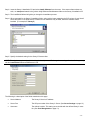
CONFIGURATION
After Sentry II is connected, the default page will be displayed.
- 12 -
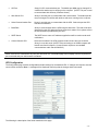
To begin the configuration, select User located in the Server section.
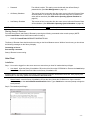
User Management
The User Management page is where the valid user accounts are set up for Sentry II. The default user is admin, which
has administrator privileges. Logging in under this account allows you to completing configure Sentry II. To add
additional users, enter the Name, Password, Confirm Password, select whether this user should have administrator
privileges, and select Save. NOTE: The information a user will be able to view is limited if an account is set up without
administrator privileges.
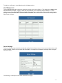
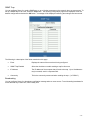
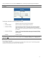
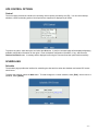
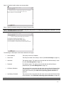
Server Settings
The Server Settings page contains the configurable settings for the Sentry II server. If your server requires values other
than the defaults, enter the correct values and select Save. A message will be displayed confirming that the changes
have been saved.
The following is a description of the fields contained on this page:
- 13 -
•
API Port
Sentry II’s API communications port. The default port 8888 may be changed if it
conflicts with another service running on the computer. (NOTE: This port is used
to communicate with all Sentry II Remote clients.)
•
Web Server Port
Sentry II uses this port to communicate with a web browser. The default port 80
may be changed if it conflicts with another web server running on the computer.
•
Serial Communications Port
Sentry II uses this port to communicate with the UPS. Select the port the UPS
has been connected to.
•
Baud Rate
Sentry II communicates with the UPS using this baud rate. This rate will be auto
detected from the UPS when the Sentry II service is started. If not, please refer to
the documentation provided with your UPS.
•
SMTP Server
The SMTP server name or IP address supplied here will be used to send email
notifications.
•
Contact Closure UPS
Select this checkbox if the UPS supports contact closure and you would like
Sentry II to use this mode. (NOTE: Units connecting to an AS400 computer will
benefit most from this feature. Contact Closure requires a non-standard
communications cable. Part # 35000015)
NOTE: If the UPS is connected to any com port other than com 1 the default page will not display until the required com
port is selected and your web browser is restarted.
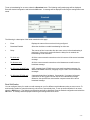
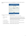
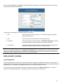
UPS Configuration
The Configuration page contains configurable and static settings for the attached UPS. If changes are required, enter the
correct values and select Save. A message will be displayed confirming that the changes have been saved.
The following is a description of the fields contained on this page:
- 14 -
•
Nominal Input Voltage
The expected input voltage.
•
Nominal Input Frequency
The input frequency provided by the UPS.
•
Nominal Output Voltage
The output voltage provided by the UPS.
•
Nominal Output Frequency
The output frequency provided by the UPS.
•
Nominal Volt-Amp Rating
The volt-amp rating provided by the UPS.
•
Nominal Output Power
The output power provided by the UPS.
•
Nominal Low Battery Time
The low battery time provided by the UPS.
•
Nominal Battery Voltage
The expected battery voltage.
•
Audible Alarm
Enable or disable the audible alarm feature of the UPS.
•
Low Voltage Transfer Point
The low voltage point at which the UPS begins to provide power.
•
Battery Installed Date
The date which the UPS first started service. (User changeable field.)
•
Nominal Battery Life
Estimated battery life of 3 years. (User changeable field.)
•
Shutdown Type
Determines the shutdown mode for the UPS. (Default of “Output” is
recommended.)
•
Auto Restart
Enable or disable the automatic restart feature of the UPS. (Default of “Enabled”
is recommended.)
NOTE: Some fields may not be supported or displayed by all UPS’s.
EVENT CONFIGURATION
Event Action
The event action page provides complete control over UPS system events. The available events vary by UPS model,
however you can configure options for Paging, Logging, SNMP Traps, Broadcast, SMTP Email, Shutdown, and System
Commands, for any available event. This allows you to take the appropriate action based on the event, such as sending a
notification of the event to the administrator.
NOTE: Some options for actions are not available for all operating systems.
- 15 -
To configure an event, select an event from the Event List. Then, select the button for the type of action to take when the
event occurs. The following sections describe how to set up each action.
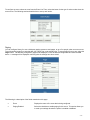
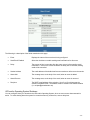
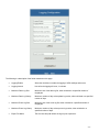
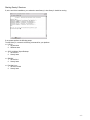
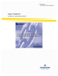
Paging
You can configure Sentry II to use a third party paging system to send pages, to up to five people, when an event occurs.
To avoid sending pages for events that last only a short time, enter a delay time. To set up paging for an event, select the
Pager button. The following configuration page will be displayed. Enter the desired configuration and select the OK
button. A message will be displayed confirming that the settings have been saved.
The following is a description of the fields contained on this page:
•
Event
Displays the name of the event that is being configured.
•
Paging Enabled
Select the checkbox to enable paging for this event. This option allows you
to retain your settings whether the option is enabled or disabled.
- 16 -
•
Delay
The amount of time in seconds, after the event occurs, before paging is
performed. If the event is removed before the delay time is reached, the
paging will be cancelled.
•
Port
The dedicated serial communications port used when paging is performed.
A modem must also be available and properly configured for this port.
•
Alarm-Add
The numeric message sent, as the page, when an event is added.
•
Alarm-Remove
The numeric message sent, as the page, when an event is removed.
•
Pager Number
Up to five separate pages may be configured. Each field must contain only
one paging phone number followed by any codes required by the paging
service to complete the page.
The phone number must contain any access numbers required for the phone
system to gain access to an outside line, such as dialing 8 or 9. Each
comma (,) represents three (3) seconds dialing pause time. This allows the
modem to pause before sending a sequence of numbers to the paging
system. There may be times, when a pause is required, before the paging
system is ready to receive the next numeric command.
It may be necessary to test the pause time until it is determined to be
functioning properly. This may require an event to be manually triggered.
See the UPS Control Options section to trigger an event.
Valid characters are limited to 0 through 9, comma (,) and the pound sign (#).
An example pager number follows: 1,8007597243,,,,,123456#,,,
The numeric 1 would be dialed.
Followed by a 3 second pause.
The numbers 8007597243 would be dialed.
Followed by a 15 second pause.
The numbers 123456 and # would be dialed.
Followed by a 9 second pause.
Then, the numeric add or remove alarm would be sent as the pager
message.
End of example.
Logging
You can configure Sentry II to log the event to the event log file. For instructions on how to view the event log, see the
View Event Log section.
To set up logging for an event, select the Logging button. The following configuration page will be displayed.
Select the Logging Enabled checkbox to enable logging for the event, and select the OK button. A message will be
displayed confirming that the settings have been saved.
- 17 -
SNMP Trap
You can configure Sentry II to send a SNMP trap, to up to 10 other computers on the network, when an event occurs. To
set up a SNMP trap for an event, select the Trap button. The following configuration page will be displayed. Enter the
desired configuration and select the OK button. A message will be displayed confirming the settings have been saved.
The following is a description of the fields contained on this page:
•
Event
Displays the name of the event that is being configured.
•
SNMP Trap Enabled
Select the checkbox to enable sending a trap for this event.
•
IP Address
The IP address of the computer that will receive the trap. Up to 10 addresses
may be entered, each in a separate field.
•
Community
This is the community name used when sending the trap. (i.e. PUBLIC)
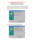
Broadcasting
You can configure Sentry II to broadcast a notification message when an event occurs. To avoid sending broadcasts for
events that last only a short time, enter a delay time.
- 18 -
To set up broadcasting for an event, select the Broadcast button. The following configuration page will be displayed.
Enter the desired configuration and select the OK button. A message will be displayed confirming the settings have been
saved.
The following is a description of the fields contained on this page:
•
Event
Displays the name of the event that is being configured.
•
Broadcast Enabled
Select the checkbox to enable broadcasting for this event.
•
Delay
The amount of time in seconds, after the event occurs, before broadcasting is
performed. If the event is removed before the delay time is reached, the
broadcasting will be cancelled.
•
For Unix only
All of the current network connections to the Unix server will be sent a broadcast
message.
•
For Netware only
All of the current network connections to the Netware server will be sent a
broadcast message.
•
For Windows 95/98/ME only
(NOT viewable) Only NT/2000 servers can send broadcast messages. On
Windows 95/98/ME machines, winpopup may be used to receive broadcast
messages.
•
For Windows NT/2000 only
A space delimited list of recipients. If an asterisk (*) is entered, all current
connections on the logged in domain will be sent a broadcast message.
Otherwise, the specified user name and/or computer name will be sent a
broadcast message.
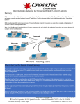
Email Notification
You can configure Sentry II to send an email message to up to five different email addresses when an event occurs. To
avoid sending emails for events that last only a short time, enter a delay time. To set up email notification for an event,
select the Email button. The following configuration page will be displayed. Enter the desired configuration and select the
OK button. A message will be displayed confirming the settings have been saved.
- 19 -
The following is a description of the fields contained on this page:
•
Event
Displays the name of the event that is being configured.
•
Send Email Enabled
Select the checkbox to enable sending email notifications for this event.
•
Delay
The amount of time in seconds, after the event occurs, before sending email
notifications. If the event is removed before the delay time is reached, sending
email will be cancelled.
•
Sender Address
The email address of the default mail account used as a reference to the sender.
•
Alarm-Add
The message sent, as the body of the email, when an event is added.
•
Alarm-Remove
The message sent, as the body of the email, when an event is removed.
•
Recipient
The SMTP email address of the recipient. Up to five (5) recipients may be
entered in separate fields. The address must be entered in the default notation
(i.e. [email protected])
UPS and/or Operating System Shutdown
You can configure Sentry II to shutdown the UPS and/or Operating System, when an event occurs that warrants this
action. To avoid shutting down the system for events that last only a short time, enter a delay time.
- 20 -
To set up shutdown for an event, select the Shutdown button. The following configuration page will be displayed.
NOTE: The Sentry II Remote client may be used to extend the system shutdown feature to multiple servers/workstations
in a network.
The following is a description of the fields contained on this page:
•
Event
Displays the name of the event that is being configured.
•
Shutdown Enabled
Select the checkbox to enable shutdown for this event.
•
Shutdown OS Delay
The amount of time in seconds, after the event occurs, before the operating
system will be shutdown. Enter –1 to disable shutting down the operating
system. If the event is removed before the delay time is reached, the action will
be cancelled.
•
Shutdown UPS Delay
The amount of time in seconds, after the event occurs, before the UPS will be
shutdown. If the event is removed before the delay time is reached, the action
will be cancelled.
•
Message
Shutdown message.
NOTE: If you are using the Sentry II Remote agent this event MUST be enabled. All Remote agents need to be configured
to shutdown before the Sentry II Server. This is accomplished with the Shutdown OS Delay and the Shutdown UPS
Delay fields.
Run a System Command
You can configure Sentry II to run an operating system command, when an event occurs. To avoid running a system
command for events that last only a short time, enter a delay time.
- 21 -
To set up a system command for an event, select the Command button. The following configuration page will be
displayed.
The following is a description of the fields contained on this page:
•
Event
Displays the name of the event that is being configured.
•
Command Enabled
Select the checkbox to enable running a system command for this event.
•
Delay
The amount of time in seconds, after the event occurs, before the system
command will be executed. If the event is removed before the delay time is
reached, the system command will be cancelled.
•
Command Path Add
The path and system command to execute when the event is added.
•
Optional Parameters Add
Parameters to pass to the system command.
•
Command Path Remove
The path and system command to execute when the event is removed.
•
Optional Parameters Remove
Parameters to pass to the system command.
- 22 -
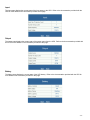
MONITORING
Meter
The meter page displays current meter readings from the UPS. This allows you to view a quick snapshot of the status of
the UPS.
Identification
The identification page displays the UPS model information. An Identification description and Attached Devices may be
entered here. To save any changes, select Save. A message will be displayed confirming that the changes have been
saved.
- 23 -
Input
The input page displays the current state of the input power to the UPS. Refer to the documentation provided with the
UPS for more details on the information provided on this page.
Output
The output page displays the current state of the output power from the UPS. Refer to the documentation provided with
the UPS for more details on the information provided on this page.
Battery
The battery page displays the current state of the UPS battery. Refer to the documentation provided with the UPS for
more details on the information provided on this page.
- 24 -
Alarm
The alarm page displays the current state of the alarms supported by the UPS.
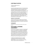
View Graphic
The view graphic page provides a current view of UPS values. The meters show nominal value ranges in green, the
thresholds in yellow, and invalid values in red.
The UPS current values and meter graphs are fully configurable and can display any values provided by the UPS.
- 25 -
If you would like to see other values, changing them is easy. To change a value or a meter, click on the title of the value
or meter and the following window will be displayed.
Select a new value from the drop-down list and select Save. The value will automatically be updated on the view graphic
page.
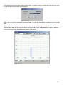
You can also view the log graph by selecting the Log Graph button. The graph is fully configurable. You can select the
UPS value, begin date, and time range to view the customized graph. Select the Refresh button to view the changes.
You can also specify the Y minimum and maximum values, whether the X and/or Y grid lines are displayed, and whether
lines or points are graphed. Select Exit to close the log graph window.
- 26 -
UPS CONTROL OPTIONS
Control
The control page provides the interface for controlling various options provided by the UPS. You can control startup,
shutdown, restart, and testing options. Not all options are supported or displayed by all UPS’s.
To perform an option, select the option and select the OK button. A perform command page will be displayed displaying
available configuration information for the option. Enter the desired configuration information, if any, and select the
Perform Command button. A message will be displayed confirming the command has been performed successfully.
SCHEDULING
Schedule
The schedule page provides the interface for scheduling the date and time when the shutdown and restart UPS events
should occur.
To add a new schedule, select the New button. To make changes to a current schedule, select [Edit]. And to remove a
schedule, select [Delete].
- 27 -
After selecting the New button or [Edit], the following page will be displayed. Select the desired shutdown and restart
configuration and select the Save button.
The following is a description of the fields contained on this page:
•
Date
The date when the event should occur. The date may easily be selected by
clicking on the date icon.
•
Time
The time when the event should occur on the specified date.
•
UPS Action
The UPS shutdown and restart settings. If Shutdown with Restart is selected,
the UPS will shutdown and then restart after n number of seconds.
•
OS Shutdown
The operating system shutdown options. If enabled, the operating system will
shutdown n number of seconds before the UPS is shutdown.
NOTE: Newer computer systems support the automatic power management feature. This feature enables the computer to
power off automatically at shutdown. If the Shutdown with Restart action is selected and your computer supports this
feature your computer will NOT power on. Please refer to the computer manufacture’s Users Manual for instructions on
changing the power management feature from within your system’s BIOS.
DATA & EVENT LOGGING
Log Configuration
The log configuration page contains the configurable settings for logging UPS readings and events on a regular basis. It
also provides options for exporting and purging the log file. To configure the logging, enter the desired settings and select
the Save button. A message will be displayed confirming that the changes have been saved.
To export the log file, enter the path and file name to exported to and select the Export Log File button. The log will
export as a comma-delimited text file. To purge the log file, select the Purge Log File button.
- 28 -
The following is a description of the fields contained on this page:
•
Logging Enable
Select the checkbox to enable the logging of UPS readings and events.
•
Logging Interval
How often the logging will occur, in minutes.
•
Maximum Data Log Size
Maximum size of the data log file, either unlimited or a specified number of
megabytes.
•
Maximum Data Log History
Maximum number of days to keep data log entries, either unlimited or a specified
number of days.
•
Maximum Event Log Size
Maximum size of the event log file, either unlimited or a specified number of
megabytes.
•
Maximum Event Log History
Maximum number of days to keep event log entries, either unlimited or a
specified number of days.
•
Export File Name
The file name and path where the log may be exported to.
- 29 -
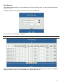
View Data Log
The view data log page allows you to select a date range of UPS log records to view. Leaving the date fields blank will
display all records.
To display the log, after selecting the desired date range, select the OK button.
A page similar to the following will be displayed.
NOTE: The data fields contained in the log may vary depending on the UPS model connected.
Select the First button to display the first page of the log. Select Previous to display the previous page. Select Next to
display the next page of the log. And select Last to view the last page of the log.
- 30 -
View Event Log
The view event log page allows you to select a date range of event log records to view. Leaving the date fields blank will
display all records.
To display the log, after selecting the desired date range, select the OK button.
A page similar to the following will be displayed.
Select the First button to display the first page of the log. Select Previous to display the previous page. Select Next to
display the next page of the log. And select Last to view the last page of the log.
SENTRY II REMOTE
Sentry II Remote was designed to extend the system shutdown capability to multiple servers/workstations in a network.
The Remote agent is available for Windows, Netware, and Unix. This gives the user cross-platform shutdown capabilities.
System Requirements
1. To use Sentry II Remote, your system must be running one of the following operating systems:
• Windows 95/98/ME
• Windows NT/2000
• SCO UnixWare/Open Desktop
• HP-UX
• IBM AIX
• Red Hat Linux
• Novell Netware 4.x, 5.x
- 31 -
2. The Sentry II Remote client MUST be on the same network as the server/workstation hosting the Sentry II Server.
3. NO other equipment is required! All Remote Clients can be automatically shutdown by one event from one
MINUTEMAN UPS.
Windows Client
Installation
Step 1. Insert the Sentry II Installation CD and select Install Software from the menu. If the autorun feature does not
work, run setup.exe located in the {cdrom drive}:\\RemoteClient\Win32 folder on the Sentry II Installation CD.
NOTE: When using a Windows NT/2000 server, logon as the administrator to ensure that you have full read and write
privileges.
Step 2. The InstallShield Wizard will guide you through the installation process.
Step 3. The default install location is recommended.
Step 4. Specify the desired setting for the Sentry II Remote client.
NOTE: This splash screen is only available during the install process. To change these settings after installation, you may
edit the C:\Program Files\Minuteman\SIIRemote\SIIRemote.ini file.
The following is a description of the fields contained on this page:
- 32 -
•
Server Address
The Sentry II Server’s IP address.
•
Server Port
The API port number of the Sentry II Server. (See Server Settings on page 13)
•
Username
The default is admin. This setting must coincide with the defined Sentry II users
list. (See User Management on page 13)
•
Password
The default is admin. This setting must coincide with the defined Sentry II
passwords list. (See User Management on page 13)
•
On Battery Shutdown
The amount of time in seconds, after the event occurs, before the Remote Client
will be shutdown. If the event is removed before the delay time is reached, the
action will be cancelled. (See UPS and/or Operating System Shutdown on
page 20)
•
Low Battery Shutdown
The amount of time in seconds, after the event occurs, before the Remote Client
will be shutdown. (See UPS and/or Operating System Shutdown on page 20)
NOTE: All Remote clients need to be configured to shutdown before the Sentry II Server.
Starting Sentry II Services
If, at the end of the installation, you selected to start Sentry II, then Sentry II should be running. If not, to start Sentry II,
perform the following steps:
•
Windows 95/98/ME
1. Click the Windows Start button and select Programs / Sentry II / SIIRemote.
2. Sentry II Remote is a hidden service and may only be seen by pressing Ctrl-Alt-Delete.
•
Windows NT/2000
1. Start the Windows Services application.
2. From the Windows Start Menu, select the Settings menu, and then select the Control Panel menu.
3. Select the Administrative Tools folder, and then select the Services application.
4. Locate the Sentry II Remote service in the services list.
5. Right click Sentry II Remote and select Start from the popup menu.
Novell Netware Client
Installation
Step 1. The Sentry II Remote must be installed from a Windows client computer. This should be done in exactly the
same manner as the Sentry II Server installation. (see Novell Netware | Install Procedure page 7)
- 33 -
Step 2. Insert the Sentry II Installation CD and select Install Software from the menu. If the autorun feature does not
work, run setup.exe located in the {cdrom drive}:\\RemoteClient\Netware folder on the Sentry II Installation CD.
Step 3. The InstallShield Wizard will guide you through the installation process.
Step 4. When prompted for the Sentry II installation folder, select a drive letter mapped to the SYS volume of your Novell
server and enter a new folder name, a maximum of 8 characters may be used, where the software will be
installed. (For example, F:\SentryII.)
Step 5. Specify the desired setting for the Sentry II Remote client.
NOTE: This splash screen is only available during the install process. To change these settings after installation, you may
edit the InstallFolder\SIIRemote\SIIRemote.ini file.
The following is a description of the fields contained on this page:
•
Server Address
The Sentry II Server’s IP address.
•
Server Port
The API port number of the Sentry II Server. (See Server Settings on page 13)
•
Username
The default is admin. This setting must coincide with the defined Sentry II users
list. (See User Management on page 13)
- 34 -
•
Password
The default is admin. This setting must coincide with the defined Sentry II
passwords list. (See User Management on page 13)
•
On Battery Shutdown
The amount of time in seconds, after the event occurs, before the Remote Client
will be shutdown. If the event is removed before the delay time is reached, the
action will be cancelled. (See UPS and/or Operating System Shutdown on
page 20)
•
Low Battery Shutdown
The amount of time in seconds, after the event occurs, before the Remote Client
will be shutdown. (See UPS and/or Operating System Shutdown on page 20)
NOTE: All Remote clients need to be configured to shutdown before the Sentry II Server.
Starting Sentry II Services
From the Novell server, start Sentry II Remote by entering the following commands at the console prompt: (NOTE:
replace InstallFolder with the folder name entered in step 4)
LOAD SYS:InstallFolder\SIIREMOTE\S2REMOTE.NLM
The Sentry II Remote client should now be executing on the Novell Netware server. Within a few minutes, you should see
the following messages on the Sentry II display:
Connecting to Server...
Successfully connected.
Sentry II Remote is now running.
Unix Client
Installation
Step 1. You must be logged in to the server as root to ensure that you have full read and write privileges.
•
Auto Install: Insert the Sentry II Installation CD into the drive. Mount the CD-ROM drive. Execute the install script
located in the \RemoteClient\Unix folder on the Sentry II Installation CD.
KNOWN ISSUE: The KDE desktop environment running with the Konqueror web browser does NOT work properly with
install scripts. For this setup, please use the Manual Install listed below.
•
Manual Install: Insert the Sentry II Installation CD into the drive. Mount the CD-ROM drive. Open a terminal
windows and go to the mnt/cdrom/RemoteClient/Unix folder. Type ./install at the command prompt to begin the
install process.
Step 2. The install script will begin.
- 35 -
Step 3. All default install locations are recommended.
Step 4. Specify the desired setting for the Sentry II Remote client.
NOTE: This splash screen is only available during the install process. To change these settings after installation, you may
edit the usr/local/sbin/SIIRemote.ini file.
The following is a description of the fields contained on this page:
•
Server Address
The Sentry II Server’s IP address.
•
Server Port
The API port number of the Sentry II Server. (See Server Settings on page 13)
•
Username
The default is admin. This setting must coincide with the defined Sentry II users
list. (See User Management on page 13)
•
Password
The default is admin. This setting must coincide with the defined Sentry II
passwords list. (See User Management on page 13)
•
On Battery Shutdown
The amount of time in seconds, after the event occurs, before the Remote Client
will be shutdown. If the event is removed before the delay time is reached, the
action will be cancelled. (See UPS and/or Operating System Shutdown on
page 20)
•
Low Battery Shutdown
The amount of time in seconds, after the event occurs, before the Remote Client
will be shutdown. (See UPS and/or Operating System Shutdown on page 20)
NOTE: All Remote clients need to be configured to shutdown before the Sentry II Server.
- 36 -
Starting Sentry II Services
If, at the end of the installation, you selected to start Sentry II, then Sentry II should be running.
If not, please perform the following steps:
To start Sentry II, execute the following commands for your platform:
HP-UX
1. cd /sbin/init.d
2. SIIRemot start
SCO UnixWare / Open Desktop
1. cd /etc/init.d
2. SentryII start
IBM AIX
1. cd /etc/init.d
2. SentryII start
Red Hat Linux
1. cd /etc/rc.d/init.d
2. SentryII start
- 37 -