1
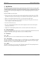
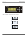
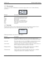
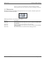
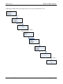
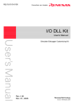
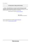
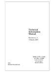
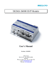
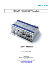
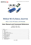
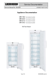
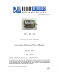
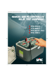
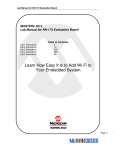
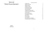
C6250 UI Module
User Manual
SELCO A/S
Betonvej 10 - DK-4000 Roskilde
Denmark
Phone: 45 7026 1122 - Fax: 45 7026 2522
e-mail: [email protected]
Web site: www.selco.com
SELCO A/S
SIGMA C6200 UI Module
Table of Contents
1
Preface .......................................................................................................................................... 3
2
Installation .................................................................................................................................... 4
2.1
Unit connections .................................................................................................................. 4
2.2
Terminals ............................................................................................................................. 4
2.2.1 Unit................................................................................................................................... 4
2.2.2 Power Supply ................................................................................................................... 4
2.2.3 RS232 ............................................................................................................................... 4
2.3
Dimensions........................................................................................................................... 5
3
4
5
6
Display ......................................................................................................................................... 6
3.1
Measurements ...................................................................................................................... 7
3.2
Protection ............................................................................................................................. 7
3.3
Plant overview...................................................................................................................... 9
Menu .......................................................................................................................................... 10
4.1
Measurements .................................................................................................................... 10
4.2
Alarm Log .......................................................................................................................... 10
4.3
Service Status ..................................................................................................................... 11
4.4
Set Date Time..................................................................................................................... 11
4.5
Config Menu/ Changing parameters .................................................................................. 12
4.6
Service Menu ..................................................................................................................... 13
4.7
Backup ............................................................................................................................... 15
4.8
Restore Config ................................................................................................................... 15
4.9
GenCtrl Info ....................................................................................................................... 15
4.10
UI Info ................................................................................................................................ 15
Upload/Download config ........................................................................................................... 16
5.1
Upload config to PC ........................................................................................................... 16
5.2
Download config to C6250 ................................................................................................ 16
Specifications ............................................................................................................................. 17
Revision: 08.09.2008
Page 2 of 17
SELCO A/S
SIGMA C6200 UI Module
1 Preface
The SELCO C6250 UI module is a display and configuration tool for the SELCO C6200
Gencontroller module. The UI module will access the configuration parameter stored in the module
and present the parameter to the operator in a user-friendly and easy accessible menu structure. The
UI module functions as a digital multi-meter, providing information about voltages, currents, load
levels, power factor etc.
Revision: 08.09.2008
Page 3 of 17
SELCO A/S
SIGMA C6200 UI Module
2 Installation
The C6200 is designed for flush mounting. Outside dimensions are H x W x D = 72 x 168 x 29mm.
A cut out with dimensions H x W = 68 x 164mm must be made in order to install the unit in the
switchboard cabinet. An installation depth of between 100 and 115mm is recommended. The C6200
is secured to the switch board plate through the use of the 4 mounting/fixing brackets included in
the package.
Install the C6200 as described below.
• Find a location in the switch board cabinet with enough installation depth to house the C6250
unit. Make sure that the selected location is also satisfactory from the operator’s point of view.
• Make a cut out with the dimensions H x W = 68 x 164 mm in the cabinet plate.
• Make sure the rubber gasket is in place behind the unit front plate. This gasket is necessary to
ensure compliance with the IP54 requirements.
• Insert the unit into the cut out.
• Place the 4 mounting/fixing brackets in the small rectangular cut outs located at the top and
bottom plates of the unit.
• Tighten the 4 mounting/fixing brackets with a screwdriver until the unit is firmly seated.
2.1 Unit connections
A serial cable (straight through cable) must be used for the communication connection between the
C6200 and C6250. Max cable length is 30meters between C6200 and C6250.
2.2 Terminals
2.2.1 Unit
The UNIT connection is used for communication between the C6200 and C6250.
2.2.2 Power Supply
The power supply works on a nominal voltage of +24 VDC. When used with C6200 Gencontroller,
the supply of C6250 is taken through the DB9 cable from C6200. Alternatively the power supply
terminals can be used e.g. when the C6250 is connected to a PC
2.2.3 RS232
The RS232 connection is used to connect the C6250 with a laptop or PC when updating the unit’s
firmware or when uploading/downloading a configuration file
Revision: 08.09.2008
Page 4 of 17
SELCO A/S
SIGMA C6200 UI Module
2.3 Dimensions
Cut out 68 x 164mm
Revision: 08.09.2008
Page 5 of 17
SELCO A/S
SIGMA C6200 UI Module
3 Display
After power up of the C6250 module the C6250 will show the following display:.
With the left ◄ and right ► arrow buttons further displays can be chosen.
Revision: 08.09.2008
Page 6 of 17
SELCO A/S
SIGMA C6200 UI Module
3.1 Measurements
After power up of the C6250 module, measurement display will be active. It shows following
parameters:
Message
Description
GenU
I3
kVAr
CosP
BusU
kW
kVA
Freq
Generator phase – phase voltage
Current flowing through phase three
Reactive power indicated as kVAr
Power factor
Bus bar phase - neutral voltage
Total active power indicated as kW.
Volt- ampere is indicated as kVA
Frequency
3.2 Protection
The protection display is used to indication of protection messages from the generator. Listed
protection messages can be reset (and cleared) by pressing the “Enter” button.
Following indications can be shown on this display:
Message
Description
Freq ctrl fault
In case the C6200 does not succeed to adjust the frequency to the
nominal level within 10s from generator start, this alarm will be issued.
Sync fault
This alarm will be issued in case C6200 has synchronized the generator
and given a C/B close command but the breaker did not close.
Sync timeout
Synchronization could not be completed within Sync timeout delay (see
RS232 configuration WRITE AUTOSYNC SYNCTIME).
Rampup timeout
Ramp up could not be completed within ramp up time (see RS232
configuration WRITE ACTLS RAMPTIME) + 10seconds.
Unload timeout
Unload could not be completed within ramp down time (see RS232
configuration WRITE ACTLS RAMPTIME) + 10seconds.
Revision: 08.09.2008
Page 7 of 17
SELCO A/S
SIGMA C6200 UI Module
Unload trip fault
C6200 has unloaded the generator and given a C/B trip command but the
C/B did not open.
Message
Description
CB open and Load
C6200 does not receive any feedback from the C/B that C/B is closed
but a current is detected through the CT inputs.
Gen idle CB closed
C/B closed feedback active while generator not running.
Volt ctrl fault
In case the C6200 does not succeed to adjust the voltage to the nominal
level within 10s from generator start, this alarm will be issued.
Rea rampup timeout
Ramp up of the reactive load could not be completed within reactive
load ramp up time (see RS232 configuration WRITE REACTLS
RAMPTIME) + 10seconds.
Prot trip timeout
C6200 has issued a protection trip but the breaker did not open.
Gen start fault
C6200 has issued a generator start command but the engine did not start
within engine start time out (15s).
Gen stop fault
C6200 has issued a generator stop command but the engine did not stop
within engine stop time out (15s after stop signal has been issued).
Fail Measure Head
Internal fault in C6200 module. Contact SELCO.
Reverse Power
C6200 has tripped the generator because of reverse power.
Excitation Loss
C6200 has tripped the generator because of loss of excitation.
Freq Deviation
C6200 has tripped the generator because of frequency deviation
(ROCOF/ df/dt) trip.
Vector Shift
C6200 has tripped the generator because of vector shift.
Over Volt
C6200 has tripped the generator because of over voltage.
Under Volt
C6200 has tripped the generator because of under voltage.
Over Freq
C6200 has tripped the generator because of over frequency.
Under Freq
C6200 has tripped the generator because of under voltage.
External Trip
External trip signal on C6200 digital input (see RS232 configuration
WRITE IOFUNC EXTTRIP).
Service Warning
Revision: 08.09.2008
The C6200 includes a service counter. When activated this service hour
counter will compare the running hours of the generator set (condition
for this is that the C/B must be closed) with the pre defined Service
Page 8 of 17
SELCO A/S
SIGMA C6200 UI Module
Interval. As soon as the running hours reach the amount of running
hours specified in the service interval, the Service Warning will activate.
3.3 Plant overview
The plant overview is used display actual generator load, reserve capacity, total plant capacity and
base load of all running generators.
Following indications can be shown on this display:
Message
Description
Sum Cap
Sum Cap. Indicates how many kW of reserve capacity is available from
the generator
Sum Load. Indicates the utilization of the generator
Plant Cap. Indicates the total power currently available to the installation
by the generators
Base Load indicates the total load of the running generators
Sum Load
Plant Cap
Base Load
Revision: 08.09.2008
Page 9 of 17
SELCO A/S
SIGMA C6200 UI Module
4 Menu
To access the menu press Enter.
From the main menu screen the operator has access to all functions of the C6200. The functions are
arranged in groups and displayed as follows:
4.1 Measurements
The measurement screen displays the current condition of the connected generator set with all
measurements and alarms. The measurement display is identical with the start up display (see 3.1)
4.2 Alarm Log
The C6200 saves the last 20 alarms. It displays one alarm at a time. Each alarm is displayed as
follows:
Log
#1
Date Time
Text
#1
This means that this is the latest alarm
Date
Date when the alarm appeared
Time
Time when the alarm appeared
Text
Alarm text. This text is identical with the text displayed in the protection display (see
3.2 Protection).
Revision: 08.09.2008
Page 10 of 17
SELCO A/S
SIGMA C6200 UI Module
4.3 Service Status
The Service Status menu displays all in formation regarding service. When entering this menu the
display will show following (Example):
SERVICE STATUS
DutyHour:
0
Next Service:
0
2008-09-03 18:55:56
DutyHour
Quantity of running hours
Next Service
Quantity of running ours until the next service
Current date
Current time
4.4 Set Date Time
Here the Date and time can be set.
Revision: 08.09.2008
Page 11 of 17
SELCO A/S
SIGMA C6200 UI Module
4.5 Config Menu/ Changing parameters
It is possible to access and change all settings of the C6200 module through the User Interface.
The example below describes how the operator can change a setting within the C6200
Gencontroller by using the C6250 UI module. To move forward or backwards in the menu use the
Left or Right arrow keys. To adjust a parameter use the Up or Down arrow keys however any
changes made will automatically be stored in the configuration file. There are no fail safes so make
changes with care.
In the example below the DBCLOSE function is changed from NO to YES
C6250
> Measurments
Alarm Log
Service Status
Press arrow down 4 times
C6250
Service Status
Set DateTime
> Config Menu
Press arrow ►
PASSWORD
0000
Type Pincode by using ►◄▼▲
After that press Enter
CONNECTION TO UNIT
MAIN MENU
>PROTECT
ALARM
FREQSTAB
Press arrow ▼3x
MAIN MENU
ALARM
FREQSTAB
>AUTOSYNC
Press arrow ►
AUTOSYNC
>DBCLOSE
GAIN
DELAY
Press arrow ►
DBCLOSE
>NO<
Choose YES by pressing ▲ or ▼
DBCLOSE
>YES<
Pressing the ”Left” arrow key a few times returns the operator to the Main menu screen
Revision: 08.09.2008
Page 12 of 17
SELCO A/S
SIGMA C6200 UI Module
4.6 Service Menu
In the Service Menu the service interval, the duty hours and service password can be set. The
service can also be confirmed from the service menu.
After After choosing SERVICE MENU the unit will ask for the service password.
After the service password has been entered, the unit will go into the service menu.
Following parameters can be accessed:
Interval
Quantity of running hours between each service.
Dutyhour
Quantity of hours the generator had run.
Confirm
This is used in order to confirm a service. After the service has been confirmed the
service alarm will be set to the amount of hours defined in Interval.
Password
Here the service password can be configured.
Revision: 08.09.2008
Page 13 of 17
SELCO A/S
SIGMA C6200 UI Module
Following example shows the change of the service password from 0 to 1111:
C6250
> Measurments
Alarm Log
Service Status
Press arrow down 5 times
C6250
Set DateTime
Config Menu
> ServiceMenu
Press arrow ►
PASSWORD
0000
Type Service Pincode by using ►◄▼▲
After that press Enter
MAIN MENU
>SERVICE
Press arrow ►
SERVICE
>INTERVAL
DUTYHOUR
CONFIRM
Press arrow ▼3X
SERVICE
DUTYHOUR
CONFIRM
>PASSWORD
Press arrow ►
PASSWORD
0
Choose Pincode by pressing ►◄▼▲
PASSWORD
1111
Revision: 08.09.2008
Page 14 of 17
SELCO A/S
SIGMA C6200 UI Module
4.7 Backup
The operator can backup the configuration file from the C6200 Gencontroller and store it in the
C6250. It is only possible to have one configuration file stored at a time. This feature can be used
when installing more than one C6200 unit and the configuration file can be used in the next
generator
Backup will save the settings of the connected C6200 Generator Controller on the C6250 UI
Module.
4.8 Restore Config
The operator can restore the configuration file from the C6250 and send it to the C6200
Gencontroller. This has to be done with care due to possible changes made in the C6200 after
backup have been made. . This feature can be used when installing more than one C6200 unit and
the configuration file can be used in the next generator.
Restore will send the settings saved on the C6250 UI Module to the C6200 Generator
Controller.
Before the settings can be send to the C6200, the C6250 UI Module will ask for the password.
4.9 GenCtrl Info
Read unit version displays C6200 revision info, Can bus address and Mod bus address. Press Enter
to return to main menu.
4.10 UI Info
This menu displays the type number and firmware version of the C6250 UI Module. Press Enter to
return to main menu.
Revision: 08.09.2008
Page 15 of 17
SELCO A/S
SIGMA C6200 UI Module
5 Upload/Download config
The C6250 is more than just a switchboard mounted user interface. It can also be used as a
programming tool for commissioning or general adjustment of unit parameters. When connecting
the C6250 to the PC it is required to use a power supply. Connection is established through the
RS232 terminal on both C6250 and the PC’s com terminal.
HyperTerminal is used to communicate with C6250 and for further information on configuring
HyperTerminal please read HyperTerminal Guide which is located on SELCO A/S webpage.
HyperTerminal commands
Commands
Description
Enable
Read config
Test keyboard
Delete config
Read version
Enables write function in the C6250
List the configuration file
Tests keyboard by pressing the buttons on the C6250
Deletes stored configurations file
Shows C6250 firmware version
5.1 Upload config to PC
The operator can upload the stored configuration file in the C6200 to a laptop or PC using the
RS232 connection on the back of the unit.
5.2 Download config to C6250
The operator can download using a laptop or PC a configuration file to the C6250.
Revision: 08.09.2008
Page 16 of 17
SELCO A/S
SIGMA C6200 UI Module
6 Specifications
Power Supply:
Display:
Dimming:
RS232
Connection:
Function:
Protocol:
Baud rate:
Parity:
Data bits:
Stop bits:
EMC / EMI tests:
Marine tests:
Connections:
Dust and Water protection:
Dimensions:
Weight:
Fixation:
+24 V DC (-30 % / +30 %) Isolated
4 x 20 Characters (backlit)
LEDs and Display backlit
5 steps by RS232 command
Customized plug, 4-wire (non-isolated)
Configuration, Debugging or firmware update
ANSI terminal
1200, 2400, 4800, 9600 or 19200 baud
None, even or odd
7 or 8
1 or 2
Plug-in screw terminals (spring terminals available as option)
IP54 at front
72 x 168 x 29mm (H x W x D)
Cut out 68 x 164 mm.
300 g
Flush mount (4 mounting brackets)
The specifications are subject to change without notice.
Revision: 08.09.2008
Page 17 of 17