1
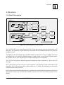
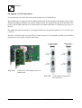
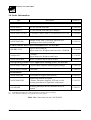
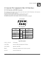
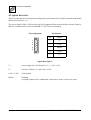
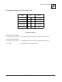
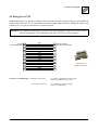
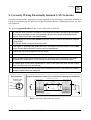
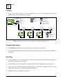
CAN-PCI/405 PCI-CAN Interface Hardware Installation and Technical Data to Product C.2023.xx Installation and Technical Data CAN-PCI/405 Rev. 1.1 Manual File: I:\texte\Doku\MANUALS\CAN\PCI\405\Englisch\CAN-PCI405_11H.en9 Date of Print: 11.07.2005 Described PCB Version: CAN-PCI/405 Rev. 1.2 Changes in the Chapters The changes in the user’s manual listed below affect changes in the hardware, as well as changes in the description of the facts only. Chapter 2.3 Changes with respect to previous revision Dimensions of the CAN-PCI/405-board changed Description of the LEDs added Further technical changes are subject to change without notice. Installation and Technical Data CAN-PCI/405 Rev. 1.1 NOTE The information in this document has been carefully checked and is believed to be entirely reliable. esd makes no warranty of any kind with regard to the material in this document, and assumes no responsibility for any errors that may appear in this document. esd reserves the right to make changes without notice to this, or any of its products, to improve reliability, performance or design. esd assumes no responsibility for the use of any circuitry other than circuitry which is part of a product of esd gmbh. esd does not convey to the purchaser of the product described herein any license under the patent rights of esd gmbh nor the rights of others. esd electronic system design gmbh Vahrenwalder Str. 207 30165 Hannover Germany Phone: Fax: E-mail: Internet: +49-511-372 98-0 +49-511-372 98-68 [email protected] www.esd-electronics.com USA / Canada: esd electronics Inc. 12 Elm Street Hatfield, MA 01038-0048 USA Phone: Fax: E-mail: Internet: +1-800-732-8006 +1-800-732-8093 [email protected] www.esd-electronics.us Installation and Technical Data CAN-PCI/405 Rev. 1.1 Contents 1. Overview . . . . . . . . . . . . . . . . . . . . . . . . . . . . . . . . . . . . . . . . . . . . . . . . . . . . . . . . . . . . . . . . . . . . 3 1.1 Module Description . . . . . . . . . . . . . . . . . . . . . . . . . . . . . . . . . . . . . . . . . . . . . . . . . . . . . . . . . 3 2. Hardware Installation . . . . . . . . . . . . . . . . . . . . . . . . . . . . . . . . . . . . . . . . . . . . . . . . . . . . . . . . . 2.1 Procedure . . . . . . . . . . . . . . . . . . . . . . . . . . . . . . . . . . . . . . . . . . . . . . . . . . . . . . . . . . . . . . . . . 2.2 PCB-View and Connectors . . . . . . . . . . . . . . . . . . . . . . . . . . . . . . . . . . . . . . . . . . . . . . . . . . . 2.3 LEDs and Connectors in the Slot Cover . . . . . . . . . . . . . . . . . . . . . . . . . . . . . . . . . . . . . . . . . 2.4 Option: 4 CAN Interfaces . . . . . . . . . . . . . . . . . . . . . . . . . . . . . . . . . . . . . . . . . . . . . . . . . . . . 4 4 6 7 8 3. Summary of Technical Data . . . . . . . . . . . . . . . . . . . . . . . . . . . . . . . . . . . . . . . . . . . . . . . . . . . . 9 3.1 General Technical Data . . . . . . . . . . . . . . . . . . . . . . . . . . . . . . . . . . . . . . . . . . . . . . . . . . . . . . 9 3.2 Microprocessor and Memory . . . . . . . . . . . . . . . . . . . . . . . . . . . . . . . . . . . . . . . . . . . . . . . . 10 3.3 PCI Bus . . . . . . . . . . . . . . . . . . . . . . . . . . . . . . . . . . . . . . . . . . . . . . . . . . . . . . . . . . . . . . . . . 10 3.4 CAN Interface . . . . . . . . . . . . . . . . . . . . . . . . . . . . . . . . . . . . . . . . . . . . . . . . . . . . . . . . . . . . 11 3.5 Software Support . . . . . . . . . . . . . . . . . . . . . . . . . . . . . . . . . . . . . . . . . . . . . . . . . . . . . . . . . . 11 3.6 Order Information . . . . . . . . . . . . . . . . . . . . . . . . . . . . . . . . . . . . . . . . . . . . . . . . . . . . . . . . . 12 4. Connector Pin Assignment of the CAN Interfaces . . . . . . . . . . . . . . . . . . . . . . . . . . . . . . . . . 4.1 CAN Interface at DSUB9 Connector . . . . . . . . . . . . . . . . . . . . . . . . . . . . . . . . . . . . . . . . . . 4.2 Option DeviceNet . . . . . . . . . . . . . . . . . . . . . . . . . . . . . . . . . . . . . . . . . . . . . . . . . . . . . . . . . 4.3 Optional Adapter of CAN2 and CAN3 . . . . . . . . . . . . . . . . . . . . . . . . . . . . . . . . . . . . . . . . . 4.4 Serial Interface at X710 . . . . . . . . . . . . . . . . . . . . . . . . . . . . . . . . . . . . . . . . . . . . . . . . . . . . . 4.5 Debug Port X720 . . . . . . . . . . . . . . . . . . . . . . . . . . . . . . . . . . . . . . . . . . . . . . . . . . . . . . . . . . 13 13 14 15 16 17 5. Correctly Wiring Electrically Isolated CAN Networks . . . . . . . . . . . . . . . . . . . . . . . . . . . . . 19 6. CAN-Bus Troubleshooting Guide . . . . . . . . . . . . . . . . . . . . . . . . . . . . . . . . . . . . . . . . . . . . . . 6.1 Termination . . . . . . . . . . . . . . . . . . . . . . . . . . . . . . . . . . . . . . . . . . . . . . . . . . . . . . . . . . . . . 6.2 CAN_H/CAN_L Voltage . . . . . . . . . . . . . . . . . . . . . . . . . . . . . . . . . . . . . . . . . . . . . . . . . . . 6.3 Ground . . . . . . . . . . . . . . . . . . . . . . . . . . . . . . . . . . . . . . . . . . . . . . . . . . . . . . . . . . . . . . . . . 6.4 CAN Transceiver Resistance Test . . . . . . . . . . . . . . . . . . . . . . . . . . . . . . . . . . . . . . . . . . . . Installation and Technical Data CAN-PCI/405 Rev. 1.1 23 23 24 24 25 1 This page is intentionally left blank. 2 Installation and Technical Data CAN-PCI/405 Rev. 1.1 Overview 1. Overview 1.1 Module Description Option Adapter Board Electrical Isolation C A N B U S CAN3 CAN2 Physical CAN Layer DSUB9 CiA pinning CAN Controller SJA1000 Ribbon Cable DC/DC Converter CAN Controller SJA1000 NVRAM (Option: NVRAM with RTC) CAN Controller SJA1000 FPGA Control Logic Flash EPROM CAN Controller SJA1000 IBM PPC405 SDRAM 10-pole post connector CAN-adapter board Electrical Isolation C A N B U S CAN1 CAN0 Physical CAN Layer DSUB9 CiA pinning DC/DC Converter 6-pole post connector Serial (TTL level) IRQ PCI Card Edge Connector Fig. 1.1.1: Block diagram of CAN-PCI/405 The CAN-PCI/405 is a PC board designed for the PCI bus that supports up to four independent CAN interfaces. Two interfaces are placed directly at the board and two additional interfaces are placed at an adapter board. The IBM PowerPC 405GP with 200 or 266 MHz enables a performance of up to 375 MIPS. The board is equipped with 16 or 64 Mbyte SDRAM and up to 8 Mbyte Flash. A non-volatile NVRAM enables the CAN-PCI/405 to save valuable process variables during power off sequences. The CAN-PCI/405 produces hardware-generated timestamps with a resolution of 1 s for all CAN messages. The CAN-PCI/405 provides two ISO 11898 compliant CAN interfaces based on SJA1000 CAN controllers. The CAN interfaces allow a data transfer rate of 1 Mbit/s. The interfaces are electrically isolated from the other potentials. Due to the powerful controller and the memory equipment it is possible for the customer to run his own applications locally at the CAN-PCI/405 module. esd offers several local operating systems for the module. Installation and Technical Data CAN-PCI/405 Rev. 1.1 3 Installation 2. Hardware Installation 2.1 Procedure Attention! Electrostatic discharge may cause damage to electronic devices. In order to avoid this please follow the instructions below before you touch the CAN module to discharge your personal static electricity: Switch off the power supply of your PC but leave the connector plug in the socket. Then touch the metal case of the PC to discharge the static electricity. Furthermore you must avoid contact between your clothes and the CAN module. Execute Hardware Installation: 1. Switch off the PC and all connected peripheral devices (monitor, printer, etc.). Switch off the CAN devices of the net to which the CAN module is to be connected. 2. Discharge yourself as described above. 3. Disconnect the power supply of the PC from the mains. 4. Remove the PC cover. Unfasten the mounting screws at the back of the PC and remove the cover. 5. Select an open PCI slot and remove the slot cover at the back of the PC. Unfasten the screw which fixes the slot cover and retain it for fixing the module afterwards. The CAN module can be inserted into every PCI slot. Be careful not to insert the board into an ISA slot, because this might damage the PC and the board! 6. Insert the CAN module into the selected PCI slot. Carefully push the board down until it snaps into place. 7. Attach the board. Use the screw you removed from the slot cover in step 5. 8. If you are installing the CAN-PCI/405 module with 4 CAN interfaces you have to install the adapter board at the back of the PC at the PCI slot next to the CAN-PCI/405. Connect the two boards with the included ribbon cable. The cables connectors are reverse-connect protected. 4 Installation and Technical Data CAN-PCI/405 Rev. 1.1 Installation 9. Replace the PC cover. Secure the cover with the according screws at the back of the PC. 10. Connect the CAN wire. Please note that the CAN bus has to be terminated at both ends! esd offers special T-connectors and terminator connectors. Additionally the CAN_GND signal has to be connected to earth at exactly one point. For easier wiring the termination connectors are equipped with an earth connector (4.8 mm fast-on, male). A CAN participant without an electrically isolated interface acts as an earth connection. The first CAN interface (CAN net 0) has to be connected via the lower DSUB connector (X1000) and the second CAN interface (net 1) has to be connected via the upper DSUB connector (X1010) of the CAN-PCI/405. If you are installing a CAN-PCI/405 with four CAN interfaces, you have to connect the third CAN interface (net 2) via the lower DSUB connector of the adapter board and the fourth CAN interface (net 3) via the upper DSUB connector of the adapter board. You will find a figure showing the connectors at page 8. 11. Reconnect the power supply of the PC. 12. Switch on the PC, the peripheral devices and the other CAN participants in any order. 13. End of hardware installation. The software installation is described in the manual ‘CAN-API, Installation und Software-Tools’. Installation and Technical Data CAN-PCI/405 Rev. 1.1 5 Installation 2.2 PCB-View and Connectors Fig. 2.2.1: View of the CAN-PCI/405 module 6 Installation and Technical Data CAN-PCI/405 Rev. 1.1 Installation 2.3 LEDs and Connectors in the Slot Cover Fig. 2.3.1: Meaning of the LEDs and connector position LED Name Description of LED (on) A CAN1-, CAN3traffic CAN-PCI/405-2: CAN-frames are being received or transmitted on CAN1 CAN-PCI/405-4: CAN-frames are being received or transmitted on CAN1 and/or CAN3 B CAN0-, CAN2traffic CAN-PCI/405-2: CAN-frames are being received or transmitted on CAN0 CAN-PCI/405-4: CAN-frames are being received or transmitted on CAN0 and/or CAN2 C Driver status/ PCI-traffic D Local CPU RUN LED off: LED on: LED flickering: No driver loaded Driver loaded Communication with CAN-board Local CPU is in RUN status (LED lights at every access to the SDRAM, therefore the LED can be blinking or permanently on in normal operation) Installation and Technical Data CAN-PCI/405 Rev. 1.1 7 Installation 2.4 Option: 4 CAN Interfaces As an option the CAN-PCI/405 can be ordered with four CAN interfaces. This module type is equipped with two additional SJA1000 CAN controllers. The physical layer of the additional CAN nets is placed at a separate adapter board. The adapter board has to be mounted close to the CAN-PCI/405 and has to be connected by the ribbon cable that is contained in the scope of delivery. The additional physical interfaces are designed identical to the physical interfaces of CAN net 0 and CAN net 1. The four-CAN option has to be specified in order because it is not possible to build a four-channel module from a two-channel module afterwards. Fig. 2.4.1: Connection of the adapter board via ribbon cable Fig. 2.4.2: CAN channel assignment to the connectors 8 Installation and Technical Data CAN-PCI/405 Rev. 1.1 Summary of Technical Data 3. Summary of Technical Data 3.1 General Technical Data Ambient temperature 0...50 C Humidity max. 90 %, non-condensing supplied by PCI bus, nominal voltage: Supply voltage 5 V ±5%, 3.3 V ±5%, typical current consumption for 2x CAN (max., at 20°C): 0,62 A at 3,3 V 0,13 A at 5 V X100 (card edge) X1000 (DSUB9/male) X1010 (DSUB9/male) X1100 (10-pole post connector) Plug-and-socket connectors - PCI bus CAN net 0 CAN net 1 adapter board for CAN net 2 and CAN net 3 The following connectors are only equipped for programming and service: X720 (10-pole SMD female con.) - debug interface X710 (6-pole post connector.) - serial interface (TTL) The following connectors are on the adapter board P130 (DSUB9/male) - CAN net 2 P130 (DSUB9/male) - CAN net 3 X100 (10-pin post connector) - connector on the adapter board for the connection of the CANPCI/405-4 via ribbon cable Dimensions 164.64 mm x 106.68 mm (without slot cover panel and CAN connectors ) Weight < 200 g Table 3.1.1: General data of the module Installation and Technical Data CAN-PCI/405 Rev. 1.1 9 Summary of Technical Data 3.2 Microprocessor and Memory CPU PowerPC 405GP, 200/266 MHz, 32 bit NVRAM (1, 2, 4, 8 MB) 32 KB NVRAM (option) Flash-EPROM up to 8 M x 8 bit Flash EEPROM SDRAM from 4 M x 32 bit SDRAM (16 Mbyte) up to 16 M x 32 bit SDRAM (64 Mbyte) Clock Real time clock (option) Table 3.2.1: Microprocessor and memory 3.3 PCI Bus Host bus PCI in compliance with PCI Local Bus Spec. 2.2 PCI data bus 32 bit Controller PPC405GP Interrupt interrupt signal A Slot position no restrictions for the slot position, PCI bridges are tolerated Board dimension PCI short card Connector PCI card edge connector Table 3.3.1: PCI bus data 10 Installation and Technical Data CAN-PCI/405 Rev. 1.1 Summary of Technical Data 3.4 CAN Interface Number of CAN interfaces 2, optionally 2 additional CAN interfaces at adapter board CAN controller SJA1000 CAN protocol CAN 2.0A/B Physical layer Physical layer according to ISO 11898, transmission rate is programmable from 10 Kbit/s to 1 Mbit/s Termination has to be done externally Electrical separation of CAN interfaces from other units and from each other separation by means of optocouplers and DC/DC converters DeviceNet Option adapter board with Phoenix Combicon style connector, optocouplers and CAN driver acc. to DeviceNet specification ‘DeviceNet Communication Model and Protocol, Rel. 2.0’ as an option for each CAN net of the CAN-PCI/405 (has to be spedified in order) Table 3.4.1: CAN interface data 3.5 Software Support Software drivers are available for Windows, Linux and real time operating systems. The firmware can be loaded from the PC into the Flash EPROM. The software installation and the software driver are described in the manual: ‘CAN API with Software Tools and Installation Notes’ order no: C.2001.21 Software packages for CANopen or DeviceNet are available for Windows. Installation and Technical Data CAN-PCI/405 Rev. 1.1 11 Summary of Technical Data 3.6 Order Information Type Description Order no. Hardware: CAN-PCI/405-2 2x CAN 2.0A/B, SJA1000 C.2023.02 CAN-PCI/405-4 4x CAN 2.0A/B, SJA1000 (incl. adapter) C.2023.04 CAN-PCI/405-TTCAN 2 CAN-nets 2.0A/B, with 1x SJA1000 and 1x TTCAN C.2038.02 Adapter board with 2 CAN-nets, physical layer according to ISO11898 (2xDSUB) C.2023.10 Accessories: CAN-PCI/405-Slot PCI-host software driver (incl. local firmware at CAN-PCI/405) : CAN-DRV-LCD Layer-2 driver software Object licence for Windows and Linux incl. CD-ROM C.1101.02 CANopen-LIC CANopen Object licence for Windows and Linux C.1101.05 CAN-PCI/405-IRIX IRIX 6.5 software driver object licence C.2023.27 Local operating systems for user applications running at the CAN-PCI/405: CAN-PCI/405-VxWOS VxWorks-BSP adaption (board support package) C.2023.30 CAN-PCI/405-LinuxOS Linux-BSP C.2023.32 CAN-PCI/405-ME User manual in English (this manual) 1*) C.2023.21 CAN-PCI/405-ENG Engineering manual in English 2*), Contents: schematic diagrams, PCB top overlay drawing, data sheets of significant components C.2023.25 CAN-API-ME Software manual for the host software driver in English 1*) C.2001.21 Documentation: 1*)... If module and manual are ordered together, the manual is free of charge. 2*)... This manual is liable for costs, please contact our support. Table 3.6.1: Order notes for the CAN-PCI/405 12 Installation and Technical Data CAN-PCI/405 Rev. 1.1 Connector Assignment 4. Connector Pin Assignment of the CAN Interfaces 4.1 CAN Interface at DSUB9 Connector The assignment of the signals to the connector pins is the same for all CAN interfaces. All connectors are 9-pole DSUBs with male contacts. Connectors on the CAN-PCI/450: X1000 (CAN0), X1010 (CAN1) Connectors on the adapter board: P130 (CAN2), X170 (CAN3) The DSUB connectors are not available, if the DeviceNet option is equipped. Pin Location: Pin Assignment: Signal Pin (CAN_GND) 6 CAN_H 7 reserved 8 reserved 9 Signal 1 reserved 2 CAN_L 3 CAN_GND 4 reserved 5 Shield 9-pole DSUB connector Signal Description: CAN_L, CAN_H... CAN signals CAN_GND ... reference GND of the physical CAN layer (CAN_GND)... optional CAN-GND Shield ... connected to computer case via slot cover panel reserved ... reserved for future use Installation and Technical Data CAN-PCI/405 Rev. 1.1 13 Connector Assignment 4.2 Option DeviceNet The DeviceNet interface is designed according to the specification ‘DeviceNet Communication Model and Protocol, Release. 2.0’. The power supply of the CAN bus driver has to be supported from external and the wiring is done by Phoenix Combicon style connectors MSTB 2.5/-GF-5.08 (or equivalent). Pin Assignment: 1 2 3 4 5 Pin Signals: Pin Signal 1 V- 2 CAN- 3 Shield 4 CAN+ 5 V+ Signal Description: V+... power supply for CAN interface (UVCC = 24 V ± 4%) V-... reference GND for V+ and CAN+/CAN- CAN+, CAN-... CAN signals Shield... 14 shielding (via high resistance RC-combination connected to earth via slot cover panel Installation and Technical Data CAN-PCI/405 Rev. 1.1 Connector Assignment 4.3 Optional Adapter of CAN2 and CAN3 Signal Pin Signal +5V 1 2 Tx0-CAN2* Tx1-CAN2* 3 4 Rx0-CAN2* Rx1-CAN2* 5 6 Tx0-CAN3* Tx1-CAN3* 7 8 Tx0-CAN3* Rx1-CAN3* 9 10-pole post connector 10 GND Signal Description: Tx0-CAN2*, Rx0-CAN2*, Tx1-CAN2*, Rx1-CAN2*... CAN signals (TTL-level) of the optional interface CAN2 Tx0-CAN3*, Rx0-CAN3*, Tx1-CAN3*, Rx1-CAN3*... CAN signals (TTL-level) of the optional interface CAN3 +5V, GND ... power supply of the adapter board Installation and Technical Data CAN-PCI/405 Rev. 1.1 15 Connector Assignment 4.4 Serial Interface at X710 The signals of the serial interface at X710 have TTL-Level! Signal Connector pin Signal +5 V 1 2 RxD TxD/STR12 3 4 GND CTS 6-pole post conncetor 5 6 RTS/STR14 Attention: The signals at the pins 3 and 6 will not only be used as TxD- and RxD-Signals. In the boot sequence of the PPC405 these signals are used to define the setting of the operation mode (Strapping Pins). The level is defined by high-impedance local resistors on the board. Therefore the user has to ensure, that no pull-up or pull-down resistors with values smaller than 10 kohm will be connected at the lines TxD/STR12 or RxD/STR14. This could happen with some modem types ! 16 Installation and Technical Data CAN-PCI/405 Rev. 1.1 Connector Assignment 4.5 Debug Port X720 With the debug port e.g. firmware updates can be executed. It can be connected via a 16-pole SMD-pin contact strip connector. It is recommended to build a simple adapter from the SMD-pin contact strip connector to a 16-pin post connector to connect the port. Attention: The SMD-pin contact strip connector case has no polarity! Take care to insert it into the correct position. The orientation of the pins of X720 is shown at page 6. to X720 1 16-pole SMD-Strip 2 3 4 5 6 7 8 9 10 11 12 13 14 15 16 TDO n.c. TDI TRST* n.c. 10k Pull-Up to 3.3V TCK n.c. TMS n.c. HALT n.c. n.c. Key (n.c.) n.c. GND Connectors to build adapter: SMD-pin contact strip: 2.54 mm post connector: 1 JTAG Connector 2 16-pole Post Connector 3 4 5 6 7 8 9 10 11 12 13 14 15 16 Example of an Adapter (Uncasted) Fa. Samtec, ‘modified pin contact strip’, order-no. MTMS-116-52-T-S-185 i.e. Fa. Harting, 16-pole, straight, order-no. 09185167324 Installation and Technical Data CAN-PCI/405 Rev. 1.1 17 This page is intentionally left blank. 18 Installation and Technical Data CAN-PCI/405 Rev. 1.1 Wiring 5. Correctly Wiring Electrically Isolated CAN Networks Generally all instructions applying for wiring regarding an electromagnetic compatible installation, wiring, cross sections of wires, material to be used, minimum distances, lightning protection, etc. have to be followed. The following general rules for the CAN wiring must be followed: 1. A CAN net must not branch (exception: short dead-end feeders) and has to be terminated by the wave impedance of the wire (generally 120 W ±10%) at both ends (between the signals CAN_L and CAN_H and not at GND)! 2. A CAN data wire requires two twisted wires and a wire to conduct the reference potential (CAN_GND)! For this the shield of the wire should be used! 3. The reference potential CAN_GND has to be connected to the earth potential (PE) at one point. Exactly one connection to earth has to be established! 4. The bit rate has to be adapted to the wire length. 5. Dead-end feeders have to kept as short as possible (l < 0.3 m)! 6. When using double shielded wires the external shield has to be connected to the earth potential (PE) at one point. There must be not more than one connection to earth. 7. A suitable type of wire (wave impedance ca. 120 : ±10%) has to be used and the voltage loss in the wire has to be considered! 8. CAN wires should not be laid directly next to disturbing sources. If this cannot be avoided, double shielded wires are preferable. Wire structure Signal assignment of wire and connection of earthing and terminator CAN wire with connectors DSUB9 connector (female or male) pin designation CAN_L CAN_GND 120 Ohm CAN_H 1 2 3 4 5 6 7 8 9 connector case DSUB9 connector (female or male) pin designation CAN_GND (at wire shield) n.c. CAN_L n.c. n.c. n.c. n.c. n.c. n.c. CAN_H n.c. n.c. n.c. n.c. n.c. n.c. n.c. n.c. = not connected 1 2 3 4 5 6 7 8 9 connector case 120 Ohm Shielded wire with transposed wires earth (PE) Figure: Structure and connection of wire Installation and Technical Data CAN-PCI/405 Rev. 1.1 19 Wiring Cabling for devices which have only one CAN connector per net use T-connector and dead-end feeder (shorter than 0.3 m) (available as accessory) Connecting CAN_GND to Protective Conductor PE CAN-Board e.g. PCI/405, CAN-USB, VME-CAN2, etc. Net 1 PE Female Connector CAN_H Terminator with PE Connector CAN_L Male Connector CAN_GND Male Terminator (Order-no.: C.1302.01) T-Connector Order-no.: C.1311.03 Net 2 Female Terminator (Order-no.: C.1301.01) l < 0,3 m T-Connector C.1311.03 T-Connector C.1311.03 l < 0,3 m CAN-CBMDIO8 CAN-Cable Order-no.: C.1323.03 T-Connector C.1311.03 l < 0,3 m CAN-CBMAI4 CAN-Cable Order-no.: C.1323.03 T-Connector C.1311.03 Terminator l < 0,3 m CAN-CBMCOM1 l < 0,3 m e.g. CAN-SPS Interface CSC595/2 or CAN-PC Board CAN-Cable Order-no.: C.1323.03 Figure: Example for correct wiring (when using single shielded wires) Terminal Resistance use external terminator, because this can later be found again more easily! 9-pin DSUB-terminator with male and female contacts and earth terminal are available as accessories Earthing CAN_GND has to be conducted in the CAN wire, because the individual esd modules are electrically isolated from each other! CAN_GND has to be connected to the earth potential (PE) at exactly one point in the net! each CAN user without electrically isolated interface works as an earthing, therefore: do not connect more than one user without potential separation! Earthing CAN e.g. be made at a connector 20 Installation and Technical Data CAN-PCI/405 Rev. 1.1 Wiring Wire Length Optical couplers are delaying the CAN signals. By using fast optical couplers and testing each board at 1 Mbit/s, however, esd CAN guarantee a reachable length of 37 m at 1 Mbit/s for most esd CAN modules within a closed net without impedance disturbances like e.g. longer dead-end feeders. (Exception: CAN-CBM-DIO8, -AI4 and AO4 (these modules work only up to 10 m with 1 Mbit/s)) Bit rate [Kbit/s] 1000 800 666.6 500 333.3 250 166 125 100 66.6 50 33.3 20 12.5 10 Typical values of reachable wire length with esd interface lmax [m] CiA recommendations (07/95) for reachable wire lengths lmin [m] 37 59 80 130 180 270 420 570 710 1000 1400 2000 3600 5400 7300 25 50 100 250 500 650 1000 2500 5000 Table: Reachable wire lengths depending on the bit rate when using esd-CAN interfaces Installation and Technical Data CAN-PCI/405 Rev. 1.1 21 Wiring Examples for CAN Wires Manufacturer Type of wire U.I. LAPP GmbH Schulze-Delitzsch-Straße 25 70565 Stuttgart Germany www.lappkabel.de e.g. UNITRONIC ®-BUS CAN UL/CSA UNITRONIC ®-BUS-FD P CAN UL/CSA ConCab GmbH Äußerer Eichwald 74535 Mainhardt Germany www.concab.de e.g. BUS-PVC-C (1 x 2 x 0,22 mm²) Order No.: 93 022 016 (UL appr.) BUS-Schleppflex-PUR-C (1 x 2 x 0,25 mm²) Order No.: 94 025 016 (UL appr.) SAB Bröckskes GmbH&Co. KG Grefrather Straße 204-212b 41749 Viersen Germany www.sab-brockskes.de e.g. SABIX® CB 620 (1 x 2 x 0,25 mm²) CB 627 (1 x 2 x 0,25 mm²) (UL/CSA approved) (UL/CSA approved) Order No.: 56202251 Order No.: 06272251 (UL appr.) Note: Completely configured CAN wires can be ordered from esd. 22 Installation and Technical Data CAN-PCI/405 Rev. 1.1 CAN-Bus Troubleshooting Guide 6. CAN-Bus Troubleshooting Guide The CAN-Bus Troubleshooting Guide is a guide to find and eliminate the most frequent hardware-error causes in the wiring of CAN-networks. 2 V 120 : CAN_H CAN_H CAN_L CAN_L CAN_GND CAN_GND 3 V 1 120 : : Figure: Simplified diagram of a CAN network 6.1 Termination The termination is used to match impedance of a node to the impedance of the transmission line being used. When impedance is mismatched, the transmitted signal is not completely absorbed by the load and a portion is reflected back into the transmission line. If the source, transmission line and load impedance are equal these reflections are eliminated. This test measures the series resistance of the CAN data pair conductors and the attached terminating resistors. To test it, please 1. Turn off all power supplies of the attached CAN nodes. 2. Measure the DC resistance between CAN_H and CAN_L at the middle and ends of the network 1 (see figure above). The measured value should be between 50 and 70 . If the value is below 50 , please make sure that: - there is no short circuit between CAN_H and CAN_L wiring - there are not more than two terminating resistors - the nodes do not have faulty transceivers. If the value is higher than 70 , please make sure that: - there are no open circuits in CAN_H or CAN_L wiring - your bus system has two terminating resistors (one at each end) and that they are 120 each. Installation and Technical Data CAN-PCI/405 Rev. 1.1 23 CAN-Bus Troubleshooting Guide 6.2 CAN_H/CAN_L Voltage Each node contains a CAN transceiver that outputs differential signals. When the network communication is idle the CAN_H and CAN_L voltages are approximately 2.5 volts. Faulty transceivers can cause the idle voltages to vary and disrupt network communication. To test for faulty transceivers, please 1. Turn on all supplies. 2. Stop all network communication. 3. Measure the DC voltage between CAN_H and GND 2 (see figure above). 4. Measure the DC voltage between CAN_L and GND 3 (see figure above). Normally the voltage should be between 2.0 V and 4.0 V. If it is lower than 2.0 V or higher than 4.0 V, it is possible that one or more nodes have faulty transceivers. For a voltage lower than 2.0 V please check CAN_H and CAN_L conductors for continuity. For a voltage higher than 4.0 V, please check for excessive voltage. To find the node with a faulty transceiver please test the CAN transceiver resistance (see next page). 6.3 Ground The shield of the CAN network has to be grounded at only one location. This test will indicate if the shielding is grounded in several places. To test it, please 1. Disconnect the shield wire from the ground. 2. Measure the DC resistance between Shield and ground. 3. Connect Shield wire to ground. The resistance should be higher than 1 M . If it is lower, please search for additional grounding of the shield wires. 24 Installation and Technical Data CAN-PCI/405 Rev. 1.1 CAN-Bus Troubleshooting Guide 6.4 CAN Transceiver Resistance Test CAN transceivers have one circuit that controls CAN_H and another circuit that controls CAN_L. Experience has shown that electrical damage to one or both of the circuits may increase the leakage current in these circuits. To measure the current leakage through the CAN circuits, please use an ohm-meter and: 1. Disconnect the node from the network. Leave the node unpowered 4 (see figure below). 2. Measure the DC resistance between CAN_H and CAN_GND 5 (see figure below). 3. Measure the DC resistance between CAN_L and CAN_GND 6 (see figure below). Normally the resistance should be between 1 M and 4 M . If it is not within this range, the CAN transceiver is probably faulty. 5 : CAN-Node 6 : CAN_H CAN_L CANTransceiver CAN_GND Disconnect CAN ! 4 Power 4 Disconnect Power ! Figure: Simplified diagram of a CAN node Installation and Technical Data CAN-PCI/405 Rev. 1.1 25