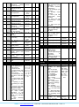
1
OK 33-THR TEMPERATURE AND HUMIDITY REGULATOR WITH PROGRAMMABLE CYCLES AND DEFROST COMMAND 2.6 3 3.1 3.2 3.3 3.4 4 4.1 4.2 4.3 4.4 4.5 4.6 4.7 4.8 4.9 4.10 4.11 4.12 4.13 4.13.1 4.13.2 4.13.3 4.13.4 4.14 4.15 4.16 4.16.1 Operating Instructions V1 INTRODUCTION This manual contains the information necessary for the correct installation, and the instructions for the use and maintenance of the product; the user is advised to read it carefully and conserve it for reference. This publication is the exclusive property of OSAKA; unless expressly authorized, reproduction and disclosure of even part of its contents is strictly prohibited. OSAKA reserves the right to make visual and functional modifications to this manual at any moment and without advance warning. In the event that a fault or malfunction of the device should create hazardous or damaging situations for persons, property or animals, note that the system must be fitted with additional devices aimed at guaranteeing safety. OSAKA and its legal representatives shall accept no responsibility for any damage caused to persons, property or animals deriving from tampering, improper or erroneous usage, or use that is not in conformity with the specifications of the appliance. INDEX 1 1.1 1.2 2 2.1 2.2 2.3 2.4 2.5 4.16.2 5 6 6.1 6.2 6.3 7 7.1 7.2 7.3 7.4 KEYPAD LOCK WARNINGS FOR INSTALLATION AND USE PERMITTED USE MECHANICAL INSTALLATION ELECTRICAL CONNECTIONS ELECTRICAL WIRING DIAGRAM OPERATION ON / STAND-BY FUNCTION CONFIGURATION OF THE INPUTS, MEASUREMENT AND DISPLAY CONFIGURATION OF THE OUTPUTS TEMPERATURE REGULATOR HUMIDITY REGULATOR RELATIONSHIPS BETWEEN CONTROL OF TEMPERATURE AND DEHUMIDIFICATION COMPRESSOR PROTECTION AND OUTPUT DELAY FUNCTIONS DEFROST CONTROLLER RECYCLING FAN CONTROL AIR EXCHANGE FAN CONTROL CELL LIGHT CONTROL AUXILIARY OUTPUT CONTROL ALARM FUNCTIONS TEMPERATURE AND HUMIDITY ALARMS EXTERNAL ALARM DOOR OPEN ALARM ALARM MEMORY OPERATION OF “F”, “UP/F1, AND “DOWN/F2” KEYS DIGITAL INPUTS WORK CYCLES AND DESCRIPTION OF TWO TYPICAL APPLICATIONS CONTROL FOR APPLICATIONS ON “LEAVENINGRETARDING / LEAVENING” CABINETS CONTROL FOR APPLICATIONS ON “CURING” CELLS TABLE OF PROGRAMMABLE PARAMETERS PROBLEMS, MAINTENANCE AND GUARANTEE SIGNALS CLEANING GUARANTEE AND REPAIRS TECHNICAL SPECIFICATIONS ELECTRICAL SPECIFICATIONS MECHANICAL SPECIFICATIONS MECHANICAL DIMENSIONS FUNCTIONAL SPECIFICATIONS 1 - DESCRIPTION OF THE APPLIANCE 1.1 - GENERAL DESCRIPTION Model OK 33-THR is a regulator with microprocessor dedicated to controlling temperature and humidity. Given its ability to manage programmable work cycles and its defrost control, it is typically used for controlling curing cells, leavening-retarding cabinets, climatic chambers and many other applications. The appliance is fitted with up to 4 relay outputs, 3 inputs for PTC or NTC temperature sensors (2 of which can also be used as digital inputs), 1 input for 0/4..20 mA humidity sensors, and a digital input, all of which are completely configurable. 1.2 - DESCRIPTION OF THE FRONT PANEL DESCRIPTION OF THE APPLIANCE GENERAL DESCRIPTION DESCRIPTION OF THE FRONT PANEL PROGRAMMING RAPID SETTING OF THE SET POINTS STANDARD PROGRAMMING OF THE PARAMETERS RAPID PROTECTION OF THE PARAMETERS BY MEANS OF PASSWORD AND KEYPAD LOCK PROGRAMMING OF THE CUSTOMIZED PARAMETERS AND LEVELS OF PARAMETER PROGRAMMING CONFIGURATION OF THE PARAMETERS WITH “KEY USB” OSAKA – www.osakasolutions.com - OK33-THR – OPERATING INSTRUCTIONS – PAGE 1 1 - SET Key: used for setting the Set point and for programming the operating parameters. In programming mode it can also be used together with the UP key for modifying the level of programming of the parameters. 2 - UP/F1 key: used for increasing the values to be set and for selecting the parameters. It can also be programmed using the “Fbu” par. for performing other functions such as manual defrosting, starting the work cycle, airexchange control, device power-on and stand-by etc. Used in conjunction with the Down key, it allows the keypad to be locked. 3 - DOWN/F2 key: used for decreasing the values to be set and for selecting the parameters. Furthermore, like the UP/F1 key, it can be programmed by means of the “Fbd” par. for performing other functions such as manual defrosting, starting the work cycle, airexchange command, device power-on and stand-by etc. Used in conjunction with the Up key, it allows the keypad to be locked. 4 - F Key: used for displaying all the variables measured by the sensors (Pr1, Pr2, Pr3, and Pr4), and for manually exiting from programming mode. Furthermore, like the UP/F1 and DOWN/F2 keys, it can be programmed by means of the “USrb” par. for performing other functions such as manual defrosting, starting the work cycle, air-exchange control, device power-on and stand-by etc. In programming mode, it can be used in conjunction with the SET Key for modifying the level of programming of the parameters. 5 - HEAT LED (Heating): indicates the status of the heating output as either on, off, or blocked (flashing) 6 - COOL LED (Cooling): indicates the status of the cooling output (compressor or other device) as either on, off, or blocked (flashing) 7 - HUM. LED (Humidification): indicates the status of the humidification output as either on, off, or blocked (flashing) 8 - DE-HUM. LED (Dehumidification): indicates a dehumidification procedure is in progress (on), not in progress, (off) or is blocked (flashing) 9 - ALARM LED: indicates the status of the alarm as either on (on), off (off) and silenced or memorized (flashing) 10 - SET LED: in programming mode, it indicates the level of programming of the parameters. It is also used for indicating Standby status. active humidity Set point (SPh1, 2, 3), and the time remaining in the phase in progress (tr 1, 2, 3). These values can be edited in the same way as the Set points. 2.2 - STANDARD PROGRAMMING OF THE PARAMETERS To gain access to the operating parameters of the appliance when the parameter protection is not active, press and hold the SET Key for approximately 5 seconds and the display will show the code that ] identifies the first group of parameters (“ SP“). Use the UP and DOWN keys to select the group of parameters that contains the parameter it is wished to edit. Once the desired group has been selected, press the SET Key and the display will show the code that identifies the first parameter of the group. Again, use the UP and DOWN keys to select the desired parameter and, when the SET Key is pressed, the display will show the code of the parameter and its setting, which can be modified by means of the UP or DOWN keys. Once the desired value has been set, press the SET Key again: the new value will be memorized and the display will again show only the code of the parameter selected. Using the UP or DOWN keys, it is then possible to select another parameter of the group and modify it as described. To go back and select another group of parameters, press the F Key for 1 sec. and the display will go back to showing the code of the group of parameters selected. At this stage, using the UP and DOWN keys, it will be possible to select another group of parameters (if there is one). At this point, if it is wished to exit from the parameter programming mode, press and hold the F Key for 1 sec. If no keys are pressed for approximately 30 sec., the appliance will automatically go to the level above until it exits from the programming mode. 2 - PROGRAMMING 2.1 - RAPID SETTING OF THE SET POINTS Press and release the SET Key and the display will indicate “SP t” (temperature Set point) and the value set. To modify this value, use the UP key to increase the value or the DOWN key to decrease it. The keys function digit-by-digit when pressed once, but if kept pressed for more than one second, the value increases or decreases rapidly and, after two seconds in the same state, the speed increases again to allow the desired value to be selected quickly. The "SP t” Set point can be set with a value comprised between the value programmed in the “SPLt” par. and the value programmed in the “SPHt” par., or it may be set as OFF (temperature regulator disabled). If, during the “SP t” setting mode, the SET Key is pressed and released again, the value set will be memorized and the display will then move on to read “SP h” (humidity Set point) and the value set for it. To modify this value, use the UP and DOWN keys. The "SP h” Set point can be set with a value comprised between the value programmed in the “SPLh” par. and the value programmed in “SPHh” par., or it may be set as OFF (humidity regulator disabled). Once the desired value has also been set for “SP h”, pressing the SET Key exits from the rapid setting mode of the Set Points. Hence, exiting from the rapid setting mode of the Sets occurs upon pressing the SET Key after the display of the final Set, or it is exited automatically in the event that no keys are pressed for approximately 15 seconds, after which the display will return to normal operating mode. Note: if there is a work cycle active, the rapid setting mode will sequentially show the active temperature Set Point (SPt1, 2, 3), the 2.3 - RAPID PROTECTION OF THE PARAMETERS BY MEANS OF PASSWORD The appliance is fitted with a function for protecting the parameters by means of a password that can be customized through the “PASS” par.. In the event it is wished to implement this protection, set the desired password number in the “PASS” parameter and exit from the parameter programming mode. In order to gain access to the parameters when the protection is active, press and hold the SET Key for around 5 seconds, after which the display will show the request for the user to enter the password, reading “r.PAS”. At this point, using the UP and DOWN keys, set the password number programmed and press the SET Key. If the password is correct, the display will show the code that identifies the first group of parameters and it will be possible to program the parameters of the appliance in the same way as described in the previous paragraph. Password protection is disabled by setting the “PASS” par. to OFF. 2.4 - PROGRAMMING OF THE CUSTOMIZED PARAMETERS AND THE LEVELS OF PARAMETER PROGRAMMING From the factory settings of the device, the protection by means of password acts on all the parameters. OSAKA – www.osakasolutions.com - OK33-THR – OPERATING INSTRUCTIONS – PAGE 2 If, after having enabled the Password by means of the “PASS” parameter, it is wished to make some parameters programmable without protection while maintaining protection on the others, follow the procedure below. Go to programming by entering the Password and select the parameter it is wished to make programmable without password protection. Once the parameter has been selected, if the SET LED is flashing, it means that the parameter can only be programmed by means of a password and is hence “protected”. To modify the visibility of the parameter, press the SET Key and, keeping it pressed, press the UP Key at the same time. The SET LED will change its state to indicate the new level of accessibility of the parameter (on = not protected; flashing = protected by means of password). In the event the Password is enabled, and in the case that certain parameters are “unprotected” when the user accesses the programming mode, all the parameters configured as “not protected” will be displayed without any division into groups, with the “r.PAS” par. listed last, by means of which it will be possible to access the “protected” parameters. NOTE: in the event of losing the password, remove the power supply from the device, press the SET Key and reconnect the device to the power while keeping the key pressed for approximately 5 sec. In this way, access is gained to all the parameters and it will hence be possible to check and modify the “PASS” parameter. 2.5 - CONFIGURATION OF THE PARAMETERS WITH “KEY USB” The appliance is equipped with a connector that allows the transfer of the operating parameters to and from the appliance through a KEY USB device, which is fitted with a 5-pole connector. The KEY USB device can be used for the serial programming of appliances that must have the same configuration of the parameters, or for keeping a copy of the programming of one appliance which can be transferred rapidly to another. The same device allows connection via the USB port to a PC with which, using the appropriate software for configuring devices, “OSAKA SetUP”, it is possible to configure the operating parameters. To use the KEY USB device, it is possible to supply power to just the device or just the appliance. SUPPLY After the 5 sec. have elapsed, the display will read “LOn” and all the functions of the keys will result as being blocked, with the exception of the display of the Set Point. If any key is pressed when the keypad is locked, the “LOn” message is shown again to indicate it is locked. To unlock the keypad, simply press and hold the UP and DOWN keys at the same time for 5 sec., after which the display will read “LOF” and all the functions of the keys will result as being operational again. 3 - WARNINGS FOR INSTALLATION AND USE 3.1 - PERMITTED USE The appliance was designed as measuring and regulating apparatus in conformity with the EN60730-1 standard for operation at an altitude of up to 2000 m. The use of the appliance in applications that are not expressly envisaged by the aforementioned standard necessitates all adequate means of protection. The appliance MAY NOT be used in environments with hazardous atmospheres (inflammable or explosive) without suitable protection. Note that the installer must ensure that the regulations relating to electromagnetic compatibility are observed, also after installing the appliance, if necessary using special filters. In the event that a fault or malfunction of the device should create hazardous or damaging situations for persons, property or animals, note that the system must be fitted with additional electromechanical devices designed to guarantee safety. 3.2 - MECHANICAL INSTALLATION The appliance is housed in a container measuring 78 x 35 mm, and is designed for built-in mounting flush with a panel within a casing. Make a cavity measuring 71 x 29 mm and insert the appliance into it, holding it in place with the special bracket provided. It is advised that the special gasket is fitted, so as to obtain the degree of frontal protection declared. Avoid positioning the internal part of the appliance in places subject to levels of humidity or dirt that could cause condensation or allow conductive objects or substances to enter the appliance. Ensure that the appliance has adequate ventilation and avoid installation in housings where there are devices located that could cause the appliance to function outside the declared temperature limits. Install the appliance as far away as possible from sources that could generate electromagnetic interference such as engines, solenoids, relay switches, electrovalves etc. 3.3 - ELECTRICAL CONNECTIONS Make the connections attaching only one conductor to each clamp and following the wiring diagram supplied, checking that the power supply voltage is the same as that indicated on the appliance, and that the absorption of the actuators connected to the appliance does not exceed the maximum current allowed. Given that it is designed to be permanently connected within an apparatus, the appliance does not have a power switch, nor is it fitted with internal power surge protection. The manufacturer hence advises the installation of a surge protection device and a double-pole switch/disconnector, labelled as a disconnection device, which interrupts the power supply of the apparatus. This switch must be positioned as close as possible to the appliance in a place that is easily accessed by the user. In addition, it is recommended that the power supply of all the SUPPLY ADAPTER circuits connected to the appliance with devices (e.g. fuses) be adequately protected from surrounding currents. Use wires with 12 VDC AC SUPPLY insulation appropriate for the voltages, the temperatures and the For further information, refer to the user manual of the KEY USB working conditions, and ensure that the wires connected to the input sensors are kept away from power supply cables and other live device. wires to avoid electromagnetic interference. If some of the cables used in the wiring are shielded, it is advised 2.6 - KEYPAD LOCK that they be earthed on one side only. For the version of the The keypad of the appliance may be completely locked. This function is useful when the controller is exposed to the public appliance with 12 V power supply, the use of the special TCTR transformer is recommended, or of a transformer with equivalent or, in any case, it is wished to block any command. To activate the keypad lock, press and hold the UP and DOWN specifications, and it is advised that a separate transformer be used keys at the same time for 5 sec. when the controller is switched on. for each apparatus, as there is no insulation between the power supply and the input. Finally, the user is advised to check that the parameters set are the desired ones, and that the application OSAKA – www.osakasolutions.com - OK33-THR – OPERATING INSTRUCTIONS – PAGE 3 functions correctly before connecting the outputs to the actuators, Using the “dP t” parameter, it is possible to establish the resolution so as to avoid anomalies in the system that could cause damage to of the desired temperature (OFF=1°; On=0.1°), and likewise with the “dP h” par., that of the humidity (OFF=1%; On=0.1%). persons, property or animals. The appliance allows the calibration of the measurements, which 3.4 - ELECTRICAL WIRING DIAGRAM can be used for recalibrating the inputs according to the requirements of the application, using the “OFS” par. (1,2,3,4). Using the “FiLt” par. (for the temperature measurements) and the Standard equipment supplied with the outputs configured as: “FiLh” par. (for the humidity measurement), it is possible to set the It is best to connect you need: out 1 = COOL, out 2 = HEAT, out 3 = HUMIDIFY, out 4 = DRY. time constant of the software filter relating to the measurement of the values at the input so as to reduce the sensitivity to Temperature probes from 1 to 3 disturbances in the measurement (increasing the time). Humidity probe CP50 or CP84, power supply 7 and signal 6. Using the “diSU” par. (for the upper display) and the “diSL” par. (for the lower display), it is possible to establish the normal messages of the display, which can show: the measurement of the 0 /4 ..2 0 m A A C T IV E desired sensor (Pr1, Pr2, Pr3, Pr4), the active temperature set point (SPt), the active humidity set point (SPh), or it is possible to have 4 ..2 0 m A the numerical display switched off (OFF). A C T IV E e x t. Independently of how the “diSU and “diSL” parameters are set, it is gen. possible to display all the variables measured in turn by pressing and releasing the F Key: the display will show the code that 4 ..2 0 m A identifies the variable (Pr 1, Pr 2 etc.) and its value. d i2 d i3 P A S S IV E ( 2 w ir e s ) This display mode is exited automatically after approximately 15 12 VDC + seconds if the F Key is not pressed again. (2 0 m A M A X ) d i1 P r1 P r3 P r4 P r2 Using the “Pr 2”, “Pr 3” and “Pr 4” parameters, it is possible to L in k T L enable (On) or disable (OFF) the measurement inputs whenever the S + sensors are not connected. In relation to the Pr2 and Pr3 inputs, by setting the related 1 2 3 4 5 6 7 8 9 10 11 12 parameters = diG, it is also possible to use these inputs as digital IN P U T S IN T E R N A L inputs whose function will be defined by the “diF2” and “diF3” BUZZER ] O u t1 : 1 6 A -A C 1 (6 A -A C 3 )/2 5 0 V A C ;1 H P 2 5 0 V A C ,1 /2 H P 1 2 5 V A C parameters present in the “ din” group (see digital input par.). O u t2 : 8 A -A C 1 (3 A -A C 3 )/2 5 0 V A C ;1 /2 H P 2 5 0 V A C ,1 /3 H P 1 2 5 V A C O u t3 ,4 : 5 A -A C 1 (2 A -A C 3 )/2 5 0 V A C ;1 /8 H P 2 5 0 V A C ,1 /1 0 H P 1 2 5 V A C Lastly, the user is reminded that the display relating to the Pr1 X33H sensor can also be modified using the display lock function while T L L (R S , K e y ) C NO C NC C NO C NO NO defrosting by means of the “dLo” par. + - + + 13 14 15 16 17 18 19 20 21 22 23 24 O UT1 O UT2 O UT3 O UT4 SU PPLY 4 - OPERATION 4.1 - ON / STAND-BY FUNCTION Once connected to the power supply, the appliance can be in one of 2 different states: - ON: means that the controller actuates the control functions. - STAND-BY: means that the controller does not actuate any function, and the display is switched off except for the SET LED. In the event of loss of power and its subsequent reinstatement, the system always returns to the state it was in before the power was cut. The ON/Stand-by command may be selected: by pressing the F Key for approximately 1 sec. if "USrb" = 4, by pressing the UP key for approximately 1 sec. if "Fbu" = 4, by pressing the DOWN key for approximately 1 sec. if "Fbd" = 4, - through one of the digital inputs if the related “diF” par. = 10 (See also the par. relating to the operation of the keys and the digital inputs) 4.2 - CONFIGURATION OF THE INPUTS, MEASUREMENT AND DISPLAY All the parameters regarding measurement are contained in the ] “ InP” group. Using the “SEnt” par., it is possible to select the type of temperature sensor (Pr1, Pr2, Pr3) it is wished to use, which can be: PTC KTY81-121 (Ptc) or NTC 103AT-2 (ntc) thermistors. Having selected the type of temperature sensor used, the “Unit” parameter can be used to select the unit of measurement of the temperature (°C or °F) Similarly, with the “SEnh” parameter, it is possible to select the type of input (Pr4) on the basis of the humidity transducer it is intended to use, which can have a 0..20 mA (0.20) or 4..20mA (4.20) output. As regards measuring humidity, it will be possible to set the "SSCh" parameter with the value that the appliance must measure in correspondence with the start of the scale (0/4 mA), and the "FSCh" parameter with the value that the appliance must measure in correspondence with the end of the scale (20 mA). 4.3 - CONFIGURATION OF THE OUTPUTS The outputs of the appliance can be configured in the group of ] “ Out” parameters, which contains the related “Out1”, “Out2”, “Out3”, and “Out4” parameters, as well as the “buF” par., which allows the configuration of the internal buzzer (if fitted). The outputs can be configured for the following operations: = CooL - for controlling the Cooling device (compressor or other) = HEAt - for controlling the Heating = rh - for controlling the humidification = drh - for controlling the dehumidification = dEF - for controlling the defrosting = FAnr - for controlling the air recycling fans (or in any case devices used for favouring the exchange of heat and humidity between the actuators and the environment) = FAnE - for controlling the air exchange / extraction fans (or in any case devices such as dampers used for favouring the exchange of air within the controlled environment) = drhE - for controlling the dehumidification device and the air exchange / extraction fans (functions like drh and FAnE in or). = LIGH - for controlling the light = AuS - for controlling an auxiliary device = ALt - for controlling a silenceable alarm device through a contact that is normally open and closed when alarmed. = AL - for controlling a non-silenceable alarm device through a contact that is normally open and closed when alarmed. = ALL - for controlling an alarm device with a memory function through a contact that is normally open and closed when alarmed. = - ALt - for controlling a silenceable alarm device through a contact that is normally closed and open when alarmed. = - AL - for controlling a non-silenceable alarm device through a contact that is normally closed and open when alarmed. = - ALL - for controlling an alarm device with a memory function through a contact that is normally closed and open when alarmed = On - Output active when the appliance is in the On state. In this mode, the output can be used for controlling the anti-condensation resistance on the door of the cell, or for controlling lights or other devices that require a power supply when the appliance is in function. = End - Output active at the end of a work cycle for the time programmed in the “btEd” par.. This mode can be used to activate external signalling (optical or acoustic) indicating the end of the OSAKA – www.osakasolutions.com - OK33-THR – OPERATING INSTRUCTIONS – PAGE 4 cycle, or to activate external automatisms (for example, product discharge automatisms). = OFF - Output disabled The “buF” par. allows the buzzer to be enabled (= YES) or disabled (=no). 4.4 - TEMPERATURE REGULATOR All the parameters regarding the regulation of the temperature are ] contained in the “ rEG” group. The regulation mode of the appliance is double-action ON/OFF-type (also known as neutral zone) and it acts on the outputs configured as “CooL” and “HEAt” on the basis of the measurements of the Pr1 sensor, the active temperature Set Point “SP t” and the intervention differential “HStt”. Tem p. P r1 H S tt SPt H S tt H um . P r4 H S th SPh H S th 0N 0N rh o ff tim e o ff 0N CooL o ff o ff 0N HEAt o ff o ff = HC - dehumidification occurs through the simultaneous activation of the outputs configured as CooL and HEAt. H um . P r4 H S th SPh H S th tim e 0N 0N HEAt o ff o ff 0N C ooL 0N rh 0N o ff o ff o ff t im e o ff 0N d rh o ff o ff 0N Remember that the operation of the temperature regulator can be C o o L conditioned by certain timing functions (protection devices for compressor, defrosting etc.), and by some priority criteria (relating If dehumidification action is not required, set “dhCn” = OFF. to the control of dehumidification) described below. Remember that the operation of the humidity regulator can be influenced by certain timing functions (protection devices for 4.5 - HUMIDITY REGULATOR All the parameters regarding the regulation of the humidity are compressor, defrosting etc.), and by some priority criteria (relating ] to the control of temperature) described below. contained in the “ rEG” group. o ff The regulation mode of the appliance is double-action ON/OFF-type (also known as neutral zone) and it acts on the outputs configured as “rh” (humidification) and “drh”, “CooL” and “HEAt” (for dehumidification depending on the setting of the “dhCn” par.) on the basis of the measurements of the Pr4 sensor, the active humidity Set Point “SP h” and the intervention differential “HSth”. Whereas the control of humidification occurs only through the output configured as rh, the control of dehumidification can be achieved in different ways, which can be established using the “dhCn” par. as: = drh - dehumidification occurs through the activation of the output configured as drh. H um . P r4 H S th SPh H S th tim e 0N rh o ff 4.6 RELATIONSHIPS BETWEEN CONTROL OF TEMPERATURE AND DEHUMIDIFICATION If the appliance is configured to operate a dehumidification control that also involves the temperature actuators (“dhCn”= drhC or HC), and there is a simultaneous request for heating/cooling and for dehumidification, the regulator will behave as follows: - if “dhCn”= drhC, the cooling action takes priority over dehumidification (in practice, if at the same time there is a request for cooling and one for dehumidification, only the CooL output is activated, and when the active temperature Set is reached, the drh output is also activated) - if dhCn= HC, the cooling action takes priority over dehumidification and the dehumidification action takes priority over heating (in practice, if at the same time there is a request for cooling and one for dehumidification, only the CooL output is activated, and when the active temperature Set is reached, the HEAt output is also activated). - If, however, there is a request for heating and at the same time a request for dehumidification, the HEAt and CooL outputs are activated and when the active humidity Set is reached, only the HEAt output remains activated. 0N o ff o ff 4.7 - COMPRESSOR PROTECTION AND OUTPUT DELAY FUNCTIONS o ff o ff d rh All the parameters regarding the compressor protection function ] and the activation delays of the outputs are contained in the “ PrC” group. = drhC - dehumidification occurs through the simultaneous The compressor protection function carried out by the apparatus is aimed at avoiding frequent interventions of any compressor activation of the outputs configured as drh and CooL. commanded by the appliance through the CooL output, and it consists of 4 time checks operating simultaneously. The first check envisages a delay in the activation of the CooL output on the basis of that which is set in the “PtC1” parameter (delay upon switching on). 0N OSAKA – www.osakasolutions.com - OK33-THR – OPERATING INSTRUCTIONS – PAGE 5 Tem p. P r1 H S tt SP t ON C ooL o ff ON ON o ff o ff tim e o ff The second check envisages a block on the activation of the related output if, from when the output was deactivated, the time set in the “PtC2” parameter (delay after power off) has not elapsed. Tem p. P r1 H S tt SP t ON ON C ooL ON o ff o ff P tC 2 tim e o ff P tC 2 P tC 2 The third check envisages a block on the activation of the related output if, from when the output was activated the last time, the time set in the “PtC3” parameter (delay between one power on and another) has not elapsed. Tem p. P r1 H S tt SP t ON C ooL ON o ff P tC 3 ON o ff P tC 3 tim e o ff P tC 3 The automatic execution of defrosting cycles occurs in accordance with the interval programmed in the “dint” par., which establishes the time that must elapse between two successive automatic defrosting cycles. Manual execution of defrosting cycles, on the other hand, can occur using one of the 3 keys (F, UP/F1, DOWN/F2), if programmed = 3, or by means of one of the 3 digital inputs, if programmed = 8 (see OPERATION OF KEYS and DIGITAL INPUTS). To start a manual defrosting cycle using the keypad, press the key programmed for the defrosting function when not in programming mode, and keep it pressed for approximately 5 seconds, after which, if the necessary conditions are in place, the appliance will carry out a defrosting cycle. Inversely, pressing the key while defrosting is in progress terminates the defrosting cycle. Using one of the 3 digital inputs, if programmed = 9, it is similarly possible to terminate a defrosting cycle in progress or to prevent defrosting cycles. The method of counting the defrosting cycle interval is established by the "dCt" par., which can be programmed as follows: = rt - interval counted as total operating time (appliance on) = ct - interval counted as compressor operating time (CooL output on). The duration of the defrosting cycle can be determined by the time or, if the evaporator sensor (Pr2) is used, when a set temperature is reached. If the evaporator sensor is not used, the duration of the cycle is established by the “dEFE” par.. If the evaporator sensor is used, defrosting ceases when the temperature measured by the Pr2 sensor exceeds the temperature set in the “tEdF” par.. If this temperature is not reached within the time set in the “dEFE” par., the defrosting is in any case interrupted. For the purpose of avoiding unnecessary defrosting cycles, the “tSdF” par. is used for setting the temperature for enabling defrosting. If the temperature measured by the evaporator sensor is higher than that set in the “tSdF” par., or than that set in the "tEdF" par., defrosting cycles are blocked. Defrosting cycles are also blocked whenever the temperature Set Point is programmed = OFF. Tem p. P r2 Lastly, the fourth check, by means of the “LCt” parameter, allows the establishment of the minimum time of activation of the output, if necessary delaying its deactivation, so as to avoid operating periods of the compressor that are too short. Similar activation delay checks are envisaged for the control of heating HEAt (“PtH” par.), for the control of humidification rh (“Pthu” par.), and for the control of dehumidification drh/CooL/HEAt (“Ptdh” par.). During all the override phases caused by the protection devices, the LED related to the action delayed is flashing. It is also possible to prevent the activation of all the outputs after the appliance is switched on for the time set in the “od” par.. During the phase of delay upon switching on, the display will show the indication od alternating with the normal programmed messages. The delay functions are deactivated when the related parameters are programmed = OFF. 4.8 - DEFROST CONTROLLER All the parameters regarding the control of defrosting, which acts on the outputs configured as “CooL” and “dEF”, are contained in the ] “ dEF” group. The type of defrosting that the appliance is to carry out is established by the “dtyP” par., which can be programmed: = EL - WITH ELECTRIC HEATING or BY COMPRESSOR STOPPAGE. In this mode, during defrosting the “CooL” output is deactivated while the “dEF” output (if configured) is activated. = in - WITH HOT GAS or CYCLE INVERSION. In this mode, during defrosting the “CooL” and “dEF” outputs are activated. tE d F tS d F ON dEF o ff 1 ON o ff 2 tim e o ff dEFE d in t d in t (d e fro s t) 3 (N O d e f.) d in t d in t (d e fro s t) Examples: defrosting cycle 1 terminates when the “tEdF” temperature is reached, defrosting cycle 2 terminates when the “dEFE” time elapses without the “tEdF” temperature being reached, and defrosting cycle 3 does not start because the temperature is higher than “tSdF”. At the end of the defrosting cycle, it is possible to delay the restarting of the compressor (“CooL” output) by the time set in the “tdCO” par. so as to allow the evaporator to drip. If it is wished to execute a defrosting cycle every time the appliance is switched on (assuming the conditions established by the “tSdF” and "tEFE" parameters are in place), it is possible to do so by programming the “SdEF” par. = yES. This makes it possible to keep the evaporator always defrosted, even when frequent power cuts occur that could cause the cancellation of various defrosting cycles. Defrosting in progress is signalled by the writing dEF on the upper display alternated with the variable established in the “diSU” par.. OSAKA – www.osakasolutions.com - OK33-THR – OPERATING INSTRUCTIONS – PAGE 6 During defrosting, it may happen that the temperature measured by the cell sensor (Pr1) increases excessively (this obviously depends on the positioning of the Pr1 sensor in relation to the evaporator). If it is wished that the appliance does not display this increase, it is possible to use the functions provided by the “dLo” par. (display locked in defrosting) and the “Etdu” par. (display unlock after defrosting differential). The “dLo” parameter = On allows the display of the Pr1 temperature to be blocked on its last reading during a complete defrosting cycle and until, after the defrosting has finished, the temperature has returned below the value [”SP t” + “Etdu”] (or the time set in the ] "dALd" par. contained in the “ AL” lock has elapsed). Or, with “dLo” = Lb, it allows the display only of the writing dEF during defrosting and, after the defrosting has finished, of the message PdEF until the Pr1 temperature has returned below the value [”SP t” + “Etdu”] (or the time set in the "dALd" par. contained ] in the “ AL” lock has elapsed). Differently, with “dLo” = OFF during defrosting, the appliance will continue to display the temperature measured by the Pr1 sensor. In the event that the display is locked and a temperature Set SPt is set = OFF, the display is immediately unlocked. Note that during the defrosting cycles, the temperature alarms are disabled during the entire cycle and also afterwards for the time set in the “dALd” par.. During the defrosting cycles, the temperature regulation is always disabled while the regulation of the humidity is established by the “dFh” par. (=On remains active; = OFF= is disabled). 4.9 - RECYCLING FAN CONTROL All the parameters regarding the control of the recycling fans (or in any case of devices used to favour the exchange of heat and humidity between the actuators and the environment) are contained ] in the “ FAn” group. The control of the recycling fans operates on the output configured as FAnr on the basis of certain control states of the appliance and of some parameters. The “FLOF” parameter allows the user to establish whether the fans must always be on during the regulation operation, independently of the state of the HEAt, CooL, rh, and drh actuators (“FLOF”=On), or whether they should switch off when all the actuators are switched off (“FLOF”=OFF). The “FdF” parameter allows the user to establish whether the recycling fans must be switched on (“FdF”=On) or whether they should switch off during defrosting (“FdF”=OFF). In this last case it is possible to delay the re-starting of the fans even after the end of defrosting by the time set in the “Fd” par.. 4.10 - AIR EXCHANGE FAN CONTROL All the parameters regarding the control of the air exchange fans (or ] extraction fans) are contained in the “ FAn” group. The control of the air exchange fans operates automatically and/or manually on the output configured as FAnE or drhE. Automatic mode is established through the “Frin” (interval) and “Fron” (duration) parameters. At the end of the interval programmed, and counted as the start up time of the appliance, the output configured as FAnE or drhE is activated for the time “Fron”. Programming “Frin” = OFF means the air exchange cycles can only be manual. A manual air exchange cycle command can occur by means of one of the 3 keys (F, UP/F1, DOWN/F2), or by means of one of the 3 digital inputs if suitably programmed (see OPERATION OF KEYS and DIGITAL INPUTS). To start a manual air exchange cycle using the keypad, press the key programmed for the air exchange function (= 5) when not in programming mode, and keep it pressed for approximately 5 seconds, after which, if the necessary conditions are in place, the appliance will perform the cycle by activating the FanE or drhE output for the time “Fron”. If the “Fron” par. is set =OFF, the duration of the cycle is infinite and hence it may only be stopped manually. By keeping the programmed key pressed for 5 seconds, it is also possible to manually interrupt the cycle in progress, whether it has been started manually or automatically (the stop command will then trigger the restart of the counting of the “Frin” interval). Similar start/stop operations of the cycle can be carried out by means of the digital inputs suitably programmed = 11. The air exchange cycle in progress is signalled by the writing FanE on the upper display alternating with the variable established in the “diSU” par.. 4.11 - CELL LIGHT CONTROL The cell light command operates on the output configured as LIGH through one of the keys or one of the digital inputs when it has been opportunely configured. The light is activated by means of one of the 3 digital inputs configured = 5, 6, 7, or by one of the 3 keys (F, UP/F1, DOWN/F2) configured = 1 (see OPERATION OF KEYS and DIGITAL INPUTS). The LIGH output can always be activated, even when the controller is in the OFF (stand-by) state. If the LIGHT output has already been activated using a key, the state of the digital input has no effect (the output must be switched off using the key). 4.12 - AUXILIARY OUTPUT CONTROL All the parameters regarding the functions of the auxiliary output are ] contained in the “ AuS” group. The auxiliary output can be configured to operate on any one of the outputs by programming the parameter related to the desired output = AuS. The function carried out is defined by means of the “FOA” par. and the operation is conditioned by the time set in the “tuA” par.. The “FOA” parameter can be configured for the following operations: = 0 - Auxiliary output not active = 1 - CooL output delayed: the auxiliary output is activated with a delay that can be set in the "tuA" parameter with respect to the output configured as CooL. The output will then be switched off at the same time as the CooL output is deactivated. This operating mode can be used for commanding a second compressor or in any case other utilities operating according to the same conditions as the CooL output, but which must be delayed with respect to the switching on of the compressor to avoid excessive current absorption. = 2 - Activation by front key (F, UP/F1, DOWN/F2) or by digital input: the output is activated through the action of a front key suitably configured for the function (= 2), or by means of the activation of a digital input, always on condition it is correctly configured (=12). These commands have bistable operation, which means, for example, that upon the first action of the key or the digital input, the output is activated, while upon the second, it is deactivated. In this mode, the AUS output can also be switched off automatically after a certain time, which can be set in the "tuA" parameter. With "tuA" = OFF, the output is activated and deactivated only manually; inversely, once it has been activated, the output is switched off automatically after the time set. This function can be used, for example, as a command for lights, for anti-fogging resistances, or for other utilities. 4.13 - ALARM FUNCTIONS All the parameters regarding the alarm functions are contained in ] the “ AL” group. Le alarm functions of the appliance act on the internal buzzer, if one is present and configured by means of the “buF” par., and on the desired output, if it is configured by means of the “Out1”, “Out2”, “Out3” or “Out4” parameters, in accordance with that which is set in the aforementioned parameters. The possible selections of these parameters for the functioning of signalling alarms are: = ALt - when it is wished that the buzzer or the output be activated under an alarm condition and that they can be manually deactivated (alarm silencing) by pressing any key on the appliance (typical application for an acoustic signal). = AL - when it is wished that the buzzer or the output be activated under an alarm condition but that they cannot be manually deactivated and are hence deactivated only at the cessation of the alarm condition (typical application for a luminous signal). = ALL - when it is wished that the buzzer or the output be activated under an alarm condition and that they remain activated also after the cessation of the alarm condition (see alarm memory). The OSAKA – www.osakasolutions.com - OK33-THR – OPERATING INSTRUCTIONS – PAGE 7 deactivation (recognition of the alarm memorized) may then occur or they will be the [”SP”+”HAL”] and [”SP”+”LAL”] values if the manually by pressing any key only after the alarm has terminated alarms are relative (“Aty”=dE). (typical application for a luminous signal). = -ALt - when it is wished to have the operation described as ALt Tem p. P r1 but with inverse operating logic (buzzer or output activated under normal condition and deactivated under an alarm condition). = -AL - when it is wished to have the operation described as AL but dAL1 HAL1 with inverse operating logic (buzzer or output activated under normal condition and deactivated under an alarm condition). SPt = -ALL - when it is wished to have the operation described as ALL LAL1 dAL1 but with inverse operating logic (buzzer or output activated under normal condition and deactivated under an alarm condition). Any active alarm condition is signalled on the display of the ON ON tim e appliance by switching on the ALARM LED. Any silenced or memorized alarm condition is signalled by the AL HI 1 LO 1 o ff o ff o ff ALARM LED flashing. The alarm conditions of the appliance are: - Errors in Sensors “E1”, “-E1”, “E2, “-E2”, “E3”, “-E3”, “E4”, “E4” - Temperature alarms “HI 1”, “LO 1”, “HI 2”, “LO 2”, “HI 3”, “LO 3”, “HI 4”, “LO 4” - External alarm “AL” - Door open alarm “AdoP” 4.13.1 - TEMPERATURE AND HUMIDITY ALARMS The temperature and humidity alarms act on the basis of the measurement of the Pr1, Pr3 (temperature) and Pr4 (humidity) sensors, of the type of alarm set in the “Aty1”, “Aty2”, and “Aty4” parameters, of the alarm thresholds set in the “HAL1”, “HAL3”, and “HAL4” parameters (maximum alarms), “LAL1”, “LAL3”, and “LAL4” parameters (minimum alarms), and of the related intervention differentials “dAL1”, “dAL3”, and “dAL4”. Using the “Aty ” parameters, it is possible to establish whether the “HAL” and “LAL” alarm thresholds should be considered as absolute (“Aty”=Ab) or relative to the active Set Point (“Aty”=dE). In the event of relative alarms referring to the Pr1 and Pr3 inputs, the relative Set point will be the active temperature Set point “SPt”, while for the Pr4 input, it will be the active humidity Set point “SPh”. Some parameters may also be used to delay the enabling and the intervention of these alarms. These parameters are: “PAL1”, “PAL3”, and “PAL4 - are the exclusion times for the temperature (1,3) and humidity (4) alarms from the switching on of the appliance whenever the appliance is under alarm conditions when switching on. “ALd1”, “ALd3”, and “ALd4” - are the times of the delays in actuating the temperature (1,3) and humidity (4) alarms “dAd1”, “dAd3”, and “dAd4” - are the exclusion times of the temperature (1,3) and humidity (4) alarms from the opening of the door. “dALd” - is the exclusion time of the temperature alarms referring to the Pr1 input after the end of a defrosting cycle (and, if programmed, also of the dripping cycle). The alarms are enabled upon the expiry of the exclusion times and activate after the “ALd” time when the temperature or humidity measured by the related sensor rises above or falls below the respective maximum and minimum alarm thresholds. The alarm thresholds will be the same as those set in the “HAL” and LAL” parameters if the alarms are absolute (“Aty”=Ab), Tem p. P r1 HAL1 dAL1 dAL1 LAL1 ON AL o ff HI 1 ON o ff LO 1 t im e Example with relative alarms of Pr1 The maximum and minimum alarms can be disabled by setting the related "HAL" and "LAL" parameters = OFF. At the same time as the alarm signal configured (buzzer and/or output), the appliance signals the alarm by switching on the ALARM LED, and showing on the display: - HI 1 in the case of maximum Pr1 temperature alarm - LO 1 in the case of minimum Pr1 temperature alarm - HI 3 in the case of maximum Pr3 temperature alarm - LO 3 in the case of minimum Pr3 temperature alarm - HI 4 in the case of maximum Pr4 humidity alarm - LO 4 in the case of minimum Pr4 humidity alarm The error message will be displayed alternatively on the display which normally shows the variable that the alarm refers to. If the display does not normally show the variable that the alarm refers to, the alarm message will be shown on the upper display alternating with the variable established in the “diSU” par.. 4.13.2 - EXTERNAL ALARM The appliance may signal an external alarm by activating a digital input with function programmed as “diF ” = 1, 2, 3, 4 (see digital inputs). At the same time as the alarm signal configured (buzzer and/or output), the appliance signals the alarm by switching on the ALARM LED, and alternately showing on the upper display AL and the variable established in the “diSU” par.. 4.13.3 - DOOR OPEN ALARM The appliance may signal a door open alarm by activating a digital input with function programmed as “diF” = 5, 6, 7 (see digital inputs). Upon the activation of the digital input and after the delay programmed in the “oAd” par., the appliance signals the alarm by activating the buzzer and the output (if present), switching on the ALARM LED, and alternately showing on the upper display “AdoP” and the variable established in the “diSU” par.. If the operation of the digital input envisages the blocking of some loads (recycling fans etc.) upon the triggering of the door open alarm, the utilities are reactivated even if the digital input remains active. 4.13.4 - ALARM MEMORY The appliance offers the possibility of availing of the alarm memory function by means of the “tAL” par.. If "tAL" = no, the appliance cancels the alarm signal when the alarm conditions have ceased; if, however, it is programmed as "yES", the ALARM LED continues to flash after the cessation of the alarm conditions, too, to indicate that an alarm has been signalled. To cancel the alarm memory signal, press any key. Remember that if it is wished to have the operation of an output (or the buzzer) with alarm memory (=ALL or =-ALL), it is necessary to set the “tAL” par. = yES. o ff Example with absolute alarms of Pr1 OSAKA – www.osakasolutions.com - OK33-THR – OPERATING INSTRUCTIONS – PAGE 8 4.14 - OPERATION OF THE “F”, “UP/F1, AND “DOWN/F2” KEYS Three of the keys of the appliance can be configured to operate other commands, in addition to their normal functions. The function of the F Key can be defined using the “USrb” parameter, that of the UP/F1 key using the “Fbu” par., and that of the DOWN/F2 key by means of the “Fbd” par., all contained in the ] “ PAn” group. The three parameters offer the same possibilities and can be configured for the following operations: = OFF - the key does not carry out any function. = 1 - Pressing the key for at least 1 sec. it is possible to activate/deactivate the light output (LIGH) = 2 - Pressing the key for at least 1 sec. it is possible to activate/deactivate the auxiliary output (AUS) configured as “FOA”=2. = 3 - Pressing the key for at least 5 sec. it is possible to activate/deactivate the manual defrosting cycles. = 4 - Pressing the key for at least 1 sec. it is possible to switch the appliance from the ON state to the Stand-by state and vice versa. = 5 - Pressing the key for at least 1 sec. it is possible start/stop an air recycling cycle. = 6 - Pressing the key for at least 1 sec. it is possible start/cancel (START/STOP) a work cycle. = 7 - Pressing the key for at least 1 sec. it is possible start/stop (START/PAUSE) a work cycle. In this mode, by keeping the key pressed for 5 sec. it is possible to cancel the cycle in progress (STOP). 4.15 - DIGITAL INPUTS All the parameters regarding the functions of the digital inputs are ] contained in the “ din” group. The appliance envisages up to 3 digital inputs for contacts free from voltage, of which one is always available while the other 2 can be used as an alternative to the Pr2 and Pr3 sensors. The use of these inputs as digital inputs is established by the setting of the “Pr2” and “Pr3” parameters = diG. The functions carried out by the digital inputs can be defined by means of the “diF1”, “diF2”, and “diF3” parameters, and the actions can be delayed with the times set respectively in the “did1”, “did2”, and “did3” parameters. The “diF” parameters can be configured for the following operations: = 0 - Digital input not active = 1 - Signalling of an external alarm with contact normally open: upon the closure of the input (and after the “did” time), the alarm is activated and the appliance alternately shows on the upper display AL and the variable established in the “diSU” par.. = 2 - Signalling of an external alarm with deactivation of all the control outputs by means of normally open contact: upon the closure of the input (and after the “did” time), all the control outputs (HEAt, CooL, rh, drh, FAnr, FanE, dEF, AuS) are deactivated, the alarm is activated and the appliance alternately shows on the upper display AL and the variable established in the “diSU” par.. = 3 - Signalling of an external alarm with deactivation of the HEAt output by means of normally open contact: upon the closure of the input (and after the “did” time), the HEAt output is deactivated, the alarm is activated and the appliance alternately shows on the upper display AL and the variable established in the “diSU” par.. = 4 - Signalling of an external alarm with deactivation of the CooL output by means of normally open contact: upon the closure of the input (and after the “did” time), the CooL output is deactivated, the alarm is activated and the appliance alternately shows on the upper display AL and the variable established in the “diSU” par.. = 5 - Cell door open with only light switching on: upon the activation of the input (and after the “did” time), the output configured as LIGh is activated and the appliance alternately shows on the upper display AdoP and the variable established in the “diSU” par.. With this operating mode, the action of the digital input also activates the time that can be set in the "oAd" par., upon the expiry of which the alarm is activated to signal that the door has remained open. When the input is deactivated, the LIGH output is switched off. If the LIGHT output has already been activated by means of a configured key (see operation of keys), the state of the input has no effect and the output must be switched off using the key. = 6 - Cell door open with light switching on and stoppage of recycling fans by means of normally open contact: upon the activation of the input (and after the “did” time), as well as the light switching on (see “diF”= 5), the recycling fans (FAnr) are stopped and the appliance alternately shows on the upper display AdoP and the variable established in the “diSU” par.. As in the previous mode, the action of the digital input also activates the time that can be set in the "oAd" par., after which the alarm is activated to signal that the door has remained open. On the occurrence of the door open alarm, the recycling fans are then re-started. = 7 - Cell door open with light switching on and with stoppage of fans and actuators by means of normally open contact: similar to “diF” = 6 but with disabling of both the recycling fans (FAnr) and the actuators (HEAt. CooL, rh, drh). On the occurrence of the door open alarm, the recycling fans and the actuators are then re-enabled. = 8 - Start defrosting command with normally open contact: upon the closure of the input (and after the “did” time), a defrosting cycle is activated. = 9 - End defrosting command with normally open contact: upon the closure of the input (and after the “did” time), the defrosting cycle is terminated if it is in progress, or defrosting is blocked. = 10 - Switch on/Switch off (Stand-by) of the appliance with normally open contact: upon the closure of the input (and after the “did” time), the appliance is switched on, while when it is opened, the appliance is put into the Stand-by state. Upon switching off, this command has priority over the key, thus if a digital input is programmed = 10 and the input is not active, the controller cannot be switched on by the key. However, if the input remains active, the controller can be switched on/off using the configured key, but when the input is deactivated, it is in any case switched off. = 11 - Air exchange cycle enabling command with normally open contact: upon the closure of the input (and after the “did” time), a work cycle is activated. If the work cycle is already in progress, the command interrupts the air exchange cycle in progress. = 12 - Auxiliary output AUS remote command with normally open contact: upon the closure of the input (and after the “did” time), the auxiliary output is activated as described in the "FOA" = 2 operating mode of the auxiliary output. = 13 - Work cycle command with START/STOP mode with normally open contact: upon the closure of the input (and after the “did” time), the cycle is started (START). Once the cycle has been started, the digital input can be deactivated. If the digital input is reactivated during the execution of the cycle, the cycle is interrupted and the appliance returns to the normal regulation state (STOP). = 14 - Work cycle command with START/PAUSE mode with normally open contact: upon the closure of the input (and after the “did” time), the cycle is started (START). Once the cycle has been started, the digital input can be deactivated. If the digital input is activated again during the execution of the cycle, the controller stops the counting of the time in progress maintaining the regulation with the values set in the phase in progress (PAUSE). At this stage it is possible to restart the cycle from the point when it was stopped, by reopening and reclosing the digital input, and use further activations and deactivations to stop it, restart it and so on. = 15 - Stop work cycle command with normally open contact: upon the closure of the input (and after the “did” time), the work cycle in progress is interrupted (STOP). In this mode, if the command is maintained, it is not possible to start work cycles. = -1, -2, -3 .....-15 - Commands similar to the previous ones but obtained with normally closed contacts and hence with inverse operating logic. 4.16 - WORK CYCLES AND DESCRIPTION OF TWO TYPICAL APPLICATIONS The appliance allows timed work cycles to be executed, which can be used in many applications including the control of climatic chambers, curing cells, or leavening-retarding/leavening cabinets. All the parameters regarding the programming of the work cycle are ] contained in the “ PrG” group. The programmable work cycle consists of three phases indicated as 1., 2., and 3., and for each phase, the following are programmable: the Duration (“tS1”, “tS2”, and “tS3” parameters), the temperature regulation Set Point (“SPt1”,”SPt2”, and “SPt3” parameters) and the Humidity regulation Set Point (“SPh1”, ”SPh2”, and “SPh3” parameters). OSAKA – www.osakasolutions.com - OK33-THR – OPERATING INSTRUCTIONS – PAGE 9 If it is wished to interrupt the cycle, activate the digital input configured =15 and the appliance returns to the normal regulation state (STOP). If the STOP command is pressed and held, it is not possible to start work cycles. c y c le Tem p. P r1 S P t2 SPt S P t3 S P t1 H um . P r4 t im e SPh3 SPh SPh2 SPh1 (S ta rt) tS 1 tS 2 tS 3 1. 2. 3. t im e (E n d ) In the event that it is wished to use a lower phase number, it is sufficient to program the time of the phase not to be executed = OFF. For example, if it is wished to carry out the cycle with only two phases, program “tS3” = OFF. Conversely, if it is wished that the control of the variable does not occur during a phase, set the related Set Point = OFF. For example, if it is not desired to control the humidity in phase .2, set “SPh2” = OFF. When the cycle is not active, the regulator operates with the normal “SPt” and “SPh” Set Points described previously. In the event that no control is desired apart from the programmed cycle, set “SPt” and “SPh” = OFF. The start/stop cycle commands can be provided by the keys of the appliance or by the digital inputs, if the relative parameters are opportunely programmed. By keys through the “USrb”, “Fbu” and “Fbd” parameters as: = 6 - START / STOP mode When the command is given by key, the cycle is started (START) If the key is pressed for approximately 1 sec. during the execution of the cycle, the cycle is interrupted and the appliance returns to the normal regulation state (STOP). = 7 - START / PAUSE + STOP mode When the command is given by key, the cycle is started (START). If the key is pressed for approximately 1 sec. during the execution of the cycle, the controller stops the counting of the time in progress maintaining the regulation with the values set in the execution phase (PAUSE). At this stage, if the key is pressed again for 1 sec., it is possible to restart the cycle from the point when it was stopped, and, each time it is pressed again for 1 sec., to stop and restart it and so on. If it is wished to interrupt the cycle, keep the key pressed for 5 sec., after which the appliance returns to the normal regulation state (STOP). By digital inputs through the “diF1”, “diF2”, and “diF3” parameters as: = 13 - START / STOP mode When the command is given by digital input, the cycle is started (START). Once the cycle has been started, the digital input can be deactivated. If the digital input is reactivated during the execution of the cycle, the cycle is interrupted and the appliance returns to the normal regulation state (STOP). = 14 and 15 - START / PAUSE (14) + STOP (15) modes Upon the activation of the digital input configured =14, the cycle is started (START). Once the cycle has been started, the digital input can be deactivated. If the digital input is activated again during the execution of the cycle, the controller stops the counting of the time in progress maintaining the regulation with the values set in the execution phase (PAUSE) Once the cycle has been paused, the digital input can be deactivated. At this stage it is possible to restart the cycle from the point when it was stopped, reactivating the digital input, and with further activations and deactivations, stop and restart it and so on. During the execution of the cycle, the lower display of the appliance shows the message “1.”, “2.” or “3.” indicating the phase in progress alternated with the normal programmed display. If the cycle is paused, the lower display of the appliance shows the message “1.P”, “2.P” or “3.P” indicating the phase in progress alternated with the normal programmed display. During the execution of the cycle, the normal procedure for the rapid setting of the Set Points allows the modification of the temperature and humidity Sets relating to the phase in execution, as well as the residual time in relation to the phase in progress. During the execution of the cycle, by pressing and releasing the SET Key several times, the appliance will display in sequence “SPt1” (or 2 or 3), “SPh1” (or 2 or 3) and “tr 1” (or 2 or 3), and the related value that can be modified with the UP or DOWN keys. The modification of the time “tr 1” (or 2 or 3) then allows the duration of the phase in progress to be increased, or decreased to 0, thus obtaining the passage to the following step. Note that the modified temperature and humidity Set values are also memorized and thereafter used for all future cycles, while the modification of the time refers only to the phase in progress. If a cycle has been started and the power supply is interrupted and subsequently returns, the appliance returns to execute the cycle from the beginning of the phase in progress at the moment the power was cut. However, if the appliance is switched off by means of the stand-by command, the cycle in progress is cancelled and, when subsequently restarted, the regulator returns to operating in normal mode on the “SP t” and “SP h” Sets. Using the “ECS” parameter it is possible to establish the behaviour of the regulator at the end of the cycle. The possible settings of the parameter are: 1 = the appliance returns to the normal regulation with the “SP t” and “SP h” Sets without giving any signalling of end of cycle. 2 = The appliance returns to the normal regulation with the “SP t” and “SP h” Sets signalling the “End” message on the lower display and activating the internal buzzer and the output configured as “End” for the time programmed in the “btEd” par.. 3 = The appliance automatically goes to Stand-by state without giving any signalling of end of cycle. 4 = The appliance automatically goes to Stand-by state signalling the “End” message on the lower display and activating the internal buzzer and the output configured as “End” for the time programmed in the “btEd” par.. 5 = The appliance continues to regulate on step3 without giving any signalling of end of cycle. 6 = The appliance continues to regulate on step3 signalling the “End” message on the lower display and activating the internal buzzer and the output configured as “End” for the time programmed in the “btEd” par.. 7 = The appliance begins to regulate again from step 2 and continues to carry out the cycle until interrupted manually. 8 = The appliance begins to regulate again from step 1 and continues to carry out the cycle until interrupted manually. 4.16.1 - CONTROL FOR APPLICATIONS ON “LEAVENINGRETARDING / LEAVENING CABINETS” The application envisages an initial cooling phase also known as “blast chilling” (in which the humidity variable is not normally controlled) for the purpose of stopping leavening and thus preserving the product in optimum state while it awaits processing and subsequent operations. The second phase envisages a heating action, which is intended to favour the leavening of the product, and the control of the humidity. At the end of the second phase, the product is ready to be processed and hence the cycle can be interrupted. OSAKA – www.osakasolutions.com - OK33-THR – OPERATING INSTRUCTIONS – PAGE 10 5 - TABLE OF PROGRAMMABLE PARAMETERS Tem p. P r1 S P t2 Below is a description of all the parameters that the appliance can be given; note that some of these may not be present because they depend on the type of appliance used. S P t1 H um . P r4 t im e SPh2 SPh1=O FF tS 1 (S ta rt) t im e tS 2 1. (E n d ) 2. Phase 1. = Blast chilling Phase 2. = Leavening However, in the event that it is envisaged that the operator cannot be present at the end of this phase, and thus cannot extract the product, it is possible to program a third maintenance phase. For this third phase, it is possible to program a duration in the “tS3” par. (at the end of which a signal is given) and then make the appliance continue to regulate with the same Set Point values (by programming “ECS” = 6) until the user interrupts the cycle manually. Tem p. P r1 S P t2 S P t3 S P t1 H um . P r4 tim e SPh3 SPh2 SPh1=O FF tS 1 (S ta rt) tS 2 1. tim e tS 3 2. (E n d ) 3. Phase 1. = Blast chilling Phase 2. = Leavening Phase 3. = Maintenance 4.16.2 - CONTROL FOR APPLICATIONS ON “CURING” CELLS The application envisages an initial cooling phase also known as “dripping” in which the humidity is not normally controlled) for the purpose of rapidly cooling the product arriving from processing, and at the same time rapidly eliminating the humidity in excess. The second phase envisages the control of temperature and humidity at established values and for this reason is also known as “running”. The third phase, on the other hand, does not typically envisage any controlling action of the temperature and humidity variables, and for precisely this reason, it is also called “break”. Note: the example shows the temperature and humidity Set Points = OFF; however, these can obviously be set at whatever value the user wishes. At the end of the third phase, the cycle resumes from phase 2. (running) and then executes phase 3. (break) again, and so on until the manual stoppage of the cycle. Note: to obtain this function of repeating the cycle from phase 2., it is necessary to set the “ECS” par. = 7 Tem p. P r1 S P t2 S P t2 S P t1 S P t3 = O F F S P t3 = O F F H um . P r4 tim e SPh2 SPh2 SPh1=O FF (S ta rt) SPh3=O FF SPh3=O FF tS 1 tS 2 tS 3 tS 2 1. 2. 3. 2. Phase 1. = Dripping Phase 2. = Running Phase 3. = Break tS 3 tim e 3 . - 2 . - e tc . ]SP group (parameters relating to the Set Points) Par. Description Range Def. Note SPLt Minimum temperature 1 -58.0 ÷ SPHt -50.0 Set point SPHt Maximum temperature SPLt ÷ 302.0 100.0 2 Set Point SPLh Minimum humidity Set 3 0.0 ÷ SPHh 0.0 point SPHh Maximum humidity Set 4 SPLh ÷ 100.0 Point 100.0 SP t temperature Set point 5 OFF/SPLt ÷ 0.0 SPHt SP h humidity Set point 6 OFF/SPLh ÷ 0.0 SPHh ]InP group (parameters relating to the measurement and the display) Par. Description Range Def. Note SEnt Type of temperature 7 Ptc - ntc Ptc sensors (Pr1, Pr2, Pr3) SEnh Type of humidity sensor 0.20 - 4.20 8 4.20 (Pr4) SSCh Lower limit of the 9 0 ÷ FSCh 0 humidity input scale (Pr4) FSCh Upper limit of the 10 SSCh ÷ 100.0 humidity input scale 100.0 (Pr4) OFS1 Calibration of the Pr1 -30.0 ÷ 30.0 11 0.0 sensor (cell °C/°F temperature) OFS2 Calibration of the Pr2 -30.0 ÷ 30.0 12 0.0 sensor (evaporator °C/°F temperature) OFS3 Calibration of the Pr3 -30.0 ÷ 30.0 13 0.0 sensor (auxiliary °C/°F temperature) OFS4 Calibration of the Pr4 -30.0 ÷ 30.0 14 0.0 sensor (cell Humidity) RH% Pr 2 Presence/use of Pr2 On - OFF 15 On sensor (evaporator diG temperature / digital input 2) Pr 3 Presence/use of Pr3 On - OFF - OFF 16 sensor (auxiliary diG temperature / digital input 3) Pr 4 Presence of Pr4 sensor On - OFF 17 On (cell humidity) Unit Unit of measurement for 18 °C - °F °C temperature dP t Decimal 19 place for On - OFF On temperature dP h Decimal 20 place for On - OFF On humidity FiLt Measurement filter for OFF ÷ 20.0 21 2.0 temperature sec FiLh Measurement filter for OFF ÷ 20.0 22 2.0 humidity sec diSU Variable 23 normally OFF - Pr1 Pr1 shown on upper display: Pr2 - Pr3 OFF = Display Off Pr4 - SPt Pr1 = Measurement of SPh Pr1 sensor (cell temp.) Pr2 = Measurement of Pr2 sensor (evaporator temp.) OSAKA – www.osakasolutions.com - OK33-THR – OPERATING INSTRUCTIONS – PAGE 11 Pr3 = Measurement of Pr3 sensor (auxiliary temp.) Pr4 = Measurement of Pr4 sensor (humidity) SPt = Active temperature Set Point SPh = Active humidity Set Point diSL Variable 24 normally OFF - Pr1 Pr4 shown on lower display: Pr2 - Pr3 OFF = Display Off Pr4 - SPt Pr1 = Measurement of SPh Pr1 sensor (cell temp.) Pr2 = Measurement of Pr2 sensor (evaporator temp.) Pr3 = Measurement of Pr3 sensor (auxiliary temp.) Pr4 = Measurement of Pr4 sensor (humidity) SPt = Active temperature Set Point SPh = Active humidity Set Point ]rEG group (parameters relating to regulation) Par. Description Range Def. Note HStt Temperature regulator 0.0 ÷ 30.0 25 1.0 intervention differential °C/°F HSth Humidity 26 regulator 0.0 ÷ 30.0 % 2.0 intervention differential RH dhCn Control 27 of OFF - drh drh dehumidification: drhC - HC OFF = no control drh = by dehumidifier output drhC = by dehumidifier output and cooling HC = by cooling and heating outputs ]PrC group (parameters relating to compressor protection and output delays) Par. Description Range Def. Note PtC1 Delay in activation of OFF ÷ 99.59 OFF 28 the cooling output min.sec (CooL ) PtC2 Blocking after switching OFF ÷ 99.59 OFF 29 off of cooling output min.sec (CooL) PtC3 Minimum time between OFF ÷ 99.59 OFF 30 two switching ons of the min.sec cooling output (CooL) LtC Minimum operating time OFF ÷ 99.59 OFF 31 of cooling output (CooL) min.sec PtH Delay in activation of OFF ÷ 99.59 OFF 32 the heating output min.sec (HEAt) Pthu Delay in activation of OFF ÷ 99.59 OFF 33 the humidification min.sec output (rh) Ptdh Delay in activation of OFF ÷ 99.59 OFF 34 the dehumidification min.sec action (depending on the control set in “dhCn”) od Delay in actuation of the OFF ÷ 99.59 OFF 35 outputs after switching min.sec on ]dEF group (parameters relating to the control of defrosting) Par. Description Range Def. Note dtyP Type of defrosting: 36 EL - in EL EL= Electric defrosting in= Defrosting by hot gas/inversion of cycle dint Defrosting interval 37 OFF ÷ 99.59 6.00 hrs.min dEFE Maximum duration of 0.01 ÷ 99.59 30.00 38 defrosting min.sec tEdF Temperature at end of - 58 ÷ 302 39 8.0 defrosting °C/°F tSdF Temperature 40 of - 58 ÷ 302 2.0 defrosting enabling °C/°F dCt Method of counting 41 rt - ct rt defrosting interval rt= real time ct= sum of operating times of the compressor (CooL output) tdCO Delay in restarting the OFF ÷ 99.59 OFF 42 compressor after min.sec defrosting (dripping) SdEF Defrosting 43 upon no - yES no switching on dLo Lock 44 of Pr1 On - OFF - OFF measurement in Lb defrosting cycle OFF= no lock On= Lock on measurement memorized at start of defrosting Lb = Lock on “dEF” writings (in defrosting) and “PdEF” (in postdefrosting) Etdu Display unlock from 45 0 ÷ 30 2.0 defrosting differential °C/°F dFh Control 46 of humidity no - yES no during defrosting ]FAn group (parameters relating to control of the fans) Par. Description Range Def. Note FLOF State of recycling fans On - OFF 47 On with loads switched off FdF State of recycling fans On - OFF 48 OFF in defrosting Fd Delay of recycling fans OFF ÷ 99.59 OFF 49 after defrosting min.sec Frin Interval of air exchange OFF ÷ 99.59 OFF 50 hrs.min Fron Duration 51 of air OFF ÷ 99.59 OFF exchange min.sec ]AL group (parameters relating to the alarms) Par. Description Range Def. Note Aty1 Type 52 of Pr1 Ab - dE Ab temperature alarms: Ab = Absolute dE =Relative to the Set HAL1 Alarm threshold for high OFF / - 58.0 OFF 53 Pr1 temperature ÷ 302.0 °C/°F LAL1 Alarm threshold for low OFF / - 58.0 OFF 54 Pr1 temperature ÷ 302.0 °C/°F dAL1 Differential 55 of Pr1 0.0 ÷ 30.0 2.0 temperature alarms °C/°F ALd1 Delay of Pr1 56 OFF ÷ 99.59 OFF temperature alarms min.sec PAL1 Exclusion time of Pr1 OFF ÷ 99.59 2.00 57 temperature alarms hrs.min from switching on dALd Exclusion time of Pr1 OFF ÷ 99.59 1.00 58 temperature alarms and hrs.min display unlock from defrosting OSAKA – www.osakasolutions.com - OK33-THR – OPERATING INSTRUCTIONS – PAGE 12 dAd1 Exclusion time of Pr1 OFF ÷ 99.59 temperature alarms hrs.min from door opening Aty3 Type 60 of Pr3 Ab - dE temperature alarms: see “Aty1” HAL3 Alarm threshold for high OFF / - 58.0 61 Pr3 temperature ÷ 302.0 °C/°F LAL3 Alarm threshold for low OFF / - 58.0 62 Pr3 temperature ÷ 302.0 °C/°F dAL3 Differential 63 of Pr3 0.0 ÷ 30.0 temperature alarms °C/°F ALd3 Delay of Pr3 64 OFF ÷ 99.59 temperature alarms min.sec PAL3 Exclusion time of Pr3 OFF ÷ 99.59 65 temperature alarms hrs.min from switching on dAd3 Exclusion time of Pr3 OFF ÷ 99.59 66 temperature alarms hrs.min from door opening Aty4 Type of Pr4 humidity 67 Ab - dE alarms: see “Aty1” HAL4 Alarm threshold for high 68 OFF / Pr4 humidity 100.0÷ 100.0 %RH LAL4 Alarm threshold for low 69 OFF / Pr4 humidity 100.0÷ 100.0 %RH dAL4 Differential 70 of Pr4 0.0 ÷ 30.0 humidity alarms %RH ALd4 Delay of Pr4 humidity 71 OFF ÷ 99.59 alarms min.sec PAL4 Exclusion time of Pr4 OFF ÷ 99.59 72 humidity alarms from hrs.min switching on dAd4 Exclusion time of Pr4 OFF ÷ 99.59 73 humidity alarms from hrs.min door opening tAL Alarm memory 74 no - yES oAd Delay of door open OFF ÷ 99.59 75 alarm min.sec ]din group (parameters relating to the digital inputs) Par. Description Range diF1 Function and operating 15 / 14 / 13 / 76 logic of digital input 1: 12 / 11 / 10 / 0 = No function 9/8/7/6/ 1 = External alarm 5/4/3/2/ 2 = External alarm with 1 / 0 / -1 / -2 / deactivation of all the -3 / -4 / -5 / control outputs 6 / -7 / -8 / -9 3 = External alarm with / -10 / -11 / deactivation of the HEAt 12 / -13 / -14 output / -15 4 = External alarm with deactivation of the CooL output 5 = Opening of door with switching on of light only 6= Opening of door with Fanr output locked and switching on of light 7= Opening of door with Fanr output locked, deactivation of the HEAt, CooL, rh, and drh outputs, and switching on of light. 8= Start defrosting command 59 OFF 9= End defrosting (and block defrosting cycles) command 10= Switch on/Switch off (Stand-by) 11= Air exchange cycle command 12= Auxiliary output command 13= Work cycle with START/STOP mode command 14 = Work cycle with START/PAUSE mode command Ab OFF OFF 2.0 OFF 2.00 OFF Ab OFF OFF 2.0 OFF 2.00 OFF no OFF Def. 0 Note 15 = Stop work cycle command diF2 Function and operating 77 15...-15 0 logic of digital input 2 (alternative to Pr2): see “diF1” diF3 Function and operating 78 15...-15 0 logic of digital input 2 (alternative to Pr3): see “diF1” did1 Delay of digital input 1 79 OFF ÷ 99.59 OFF min.sec did2 Delay of digital input 2 80 OFF ÷ 99.59 OFF min.sec did3 Delay of digital input 3 81 OFF ÷ 99.59 OFF min.sec ]AuS group (parameters relating to the auxiliary output) Par. Description Range Def. Note FOA Operating 82 mode of 0/1/2 0 auxiliary output 0= No Function 1= CooL output delayed (depending on compressor) 2= Manual activation by key or digital input tuA Time relating to 83 OFF ÷ 99.59 OFF auxiliary output 1 min.sec ]Out group (parameters relating to the configuration of the outputs) Par. Description Range Def. Note Out1 Configuration 84 of OFF/ CooL/ CooL operation of OUT1 HEAt/ rh / output: drh / dEF / OFF= No Function FAnr / FAnE CooL= Cold control / drhE / LIGH HEAt = Hot control / AuS / ALt / rh = Humidifier AL / ALL / drh = Dehumidifier ALt / -AL / dEF= Defroster ALL / On / FAnr = Cell fan End FAnE = Extractor/air exchange fan drhE = Dehumidifier + extractor/air exchange LIGH = Light AuS = Auxiliary ALt = Silenceable alarm AL = Non-silenceable alarm ALL = Memorized alarm On = Active in ON state End = Signalling of end of cycle Out2 Configuration 85 of OFF/ CooL/ HEAt operation of OUT2 HEAt/ rh / output: see “Out1” drh / dEF / OSAKA – www.osakasolutions.com - OK33-THR – OPERATING INSTRUCTIONS – PAGE 13 86 Out3 Configuration of operation of OUT3 output: see “Out1” 87 Out4 Configuration of operation of OUT4 output: see “Out1” FAnr / FAnE / drhE / LIGH / AuS / ALt / AL / ALL / ALt / -AL / ALL / On / End OFF/ CooL/ HEAt/ rh / drh / dEF / FAnr / FAnE / drhE / LIGH / AuS / ALt / AL / ALL / ALt / -AL / ALL / On / End OFF/ CooL/ HEAt/ rh / drh / dEF / FAnr / FAnE / drhE / LIGH / AuS / ALt / AL / ALL / ALt / -AL / ALL / On / End yES / no 100 101 102 rH drh buF Configuration of yES operation of buzzer ]PAn group (parameters relating to the configuration of the keypad) Par. Description Range Def. Note USrb Operating mode of F OFF / 1 / 2 / OFF 89 Key: 3/4/5/6 OFF= No Function 1= Light command 2= Auxiliary output command 3= Defrosting command 4= Switch on/Switch off (Stand-by) 5= Air recycling cycle command 6= Work Cycle with START/STOP mode command 6= Work Cycle with START/PAUSE-STOP mode command Fbu Operating 90 mode of OFF / 1 / 2 / OFF UP/F1 key: see “USrb” 3/4/5/6 Fbd Operating 91 mode of OFF / 1 / 2 / OFF DOWN/F2 key: see 3 / 4 / 5 / 6 “USrb” PASS Password for access to OFF ÷ 9999 OFF 92 the operating parameters ]PrG group (Parameters relating to the work cycles) Par. Description Range Def. Note SPt1 Step 1 temperature Set OFF/SPLt ÷ 93 0.0 Point SPHt SPh1 Step 1 humidity Set OFF/SPLh ÷ 0.0 94 Point SPHh tS1 Step 1 duration time 95 OFF ÷ 99.59 OFF hrs.min SPt2 Step 2 temperature Set OFF/SPLt ÷ 96 0.0 Point SPHt SPh2 Step 2 humidity Set OFF/SPLh ÷ 0.0 97 Point SPHh tS2 Step 2 duration time 98 OFF ÷ 99.59 OFF hrs.min SPt3 Step 3 temperature Set OFF/SPLt ÷ 99 0.0 Point SPHt 88 103 SPh3 Step 3 humidity Set OFF/SPLh ÷ Point SPHh tS3 Step 3 duration time OFF ÷ 99.59 hrs.min ECS Behaviour at end of 1 / 2 / 3 / 4 / cycles: 5/6/7/8 1= Returns to normal regulation (without any signalling) 2= Returns to normal signalling “End” and activating the buzzer for the time “btEd” 3= Switches off regulator (stand-by) without any signalling 4= Switches off regulator (stand-by) signalling “End” and activating the buzzer for the time “btEd” 5= Continues to regulate on step3 (without any signalling) 6= Continues to regulate on step3 signalling “End” and activating the buzzer for the time “btEd” at the end of step 3 7= Resumes regulating from step 2 (and continues the cycle) 8= Resumes regulating from step 1 (and continues the cycle) btEd Time of activation of the OFF ÷ 99.59 buzzer for signalling the min.sec. end of the cycle 0.0 OFF 1 OFF 6 - PROBLEMS, MAINTENANCE AND GUARANTEE 6.1 - SIGNALS Error signals: Error Motive E1 The Pr1 sensor may be -E1 interrupted or short circuited, or it measures a value outside the allowed range E2 The Pr2 sensor may be -E2 interrupted or short circuited, or it measures a value outside the allowed range E3 The Pr3 sensor may be -E3 interrupted or short circuited, or it measures a value outside the allowed range E4 The Pr4 sensor may be -E4 interrupted or short circuited, or it measures a value outside the allowed range EEPr Internal memory error Action Check the correct connection of the sensor to the appliance and then check the correct operation of the sensor Check, and necessary, reprogram operating parameters. OSAKA – www.osakasolutions.com - OK33-THR – OPERATING INSTRUCTIONS – PAGE 14 if the Other signals: Signal od HI 1 LO 1 HI 3 LO 3 HI 4 LO 4 od dEF PdEF AL AdoP 1. / 2. / 3. 1.P / 2.P / 3.P End Motive Delay upon switching on in progress Maximum Pr1 temperature alarm Minimum Pr1 temperature alarm Maximum Pr3 temperature alarm Minimum Pr3 temperature alarm Maximum Pr4 humidity alarm Minimum Pr4 humidity alarm Delay upon switching on in progress Defrosting in progress with “dLo”=Lb Post-defrosting in progress with “dLo”=Lb Digital input in progress alarm Door open Cycle in execution Cycle in execution in pause phase Cycle terminated Degree of pollution: 2 Ambient working temperature: 0 T 50 °C Ambient working humidity: < 95 RH% without condensation Temperature of transport and storage: -25 T 60 °C 7.3 - MECHANICAL DIMENSIONS, DRILLING AND FIXING [mm] 6.2 - CLEANING It is recommended that the appliance only be cleaned using a soft cloth dampened with water or a non-abrasive detergent that does not contain solvents. 6.3 - GUARANTEE AND REPAIRS The appliance is guaranteed against defects in construction or material defects encountered within 12 months of delivery. The guarantee is limited to the repair or replacement of the product. Any opening of the housing, tampering with the appliance, or noncompliant use and installation of the product automatically voids the guarantee. The equipment must be adequately protected from water and dust according to the application and must be accessible only with the use of a tool (except front). If defective product under warranty or out of warranty service, contact the sales dealer for RMA authorization (document repair). 7 - TECHNICAL SPECIFICATIONS 7.1 - ELECTRICAL SPECIFICATIONS Power supply: 100...240 V AC +/- 10% AC frequency: 50/60 Hz Absorption: 4 VA approximately Input/s: 3 inputs for NTC (103AT-2, 10 K @ 25 °C) or PTC (KTY 81-121, 990 @ 25° C) temperature sensors; 1 0/4..20 mA input; 1 digital input for voltage-free contacts + 2 digital inputs for voltagefree contacts as an alternative to the Pr2 and Pr3 temperature inputs. Output/s: up to 4 relay outputs. Out1 SPST (16A-AC1, 6A-AC3 250 V AC, 1 HP 250 V AC, 1/2HP 125 V AC); Out2 SPDT (8A-AC1, 3AAC3 250 V AC,1/2 HP 250 V AC, 1/3HP 125 V AC); Out3 and Out4 SPST-NO (5A-AC1, 2A-AC3 250 V AC, 1/8 HP 250 V AC, 1/10HP 125 V AC). 12 A Max. for model with extractable terminal block Electrical lifetime of relay outputs: 100,000 op. Action: type 1.B compliant with EN 60730-1 Overvoltage category: II Device class: Class II Insulation: Reinforced between parts under low voltage (type H power supply and relay outputs) and frontal; reinforced between parts under low voltage (type H power supply and relay outputs) and parts under very low voltage (inputs); reinforced between power supply and relay outputs. 7.4 - FUNCTIONAL SPECIFICATIONS Temperature and humidity regulation: ON/OFF Control of defrosting cycles: at intervals for compressor stoppage, electrical or hot gas/cycle inversion. Range of measurements: NTC: -50...109 °C / -58...228 °F; PTC: 50...150 °C / -58 ... 302 °F; Humidity: 0...100 % %RH Resolution of the display: 1 or 0.1 Total precision:+/- (0.5 % fs + 1 digit) Time of measurement sampling: 130 ms Display: 4 digit. 1 Red and 1 Amber yellow, h 7 mm Class and structure of the software: Class A Conformity: Directives 2004/108/CE (EN55022: class B; EN610004-2: 8KV air, 4KV cont.; EN61000-4-3: 10V/m; EN61000-4-4: 2KV supply, inputs, outputs; EN61000-4-5: supply 2KV com. mode, 1 KV\ diff. mode; EN61000-4-6: 3V), 2006/95/CE (EN 60730-1, EN 60730-2-7, EN 60730-2-9) 7.2 - MECHANICAL SPECIFICATIONS Container: Self-extinguishing plastic UL 94 V0 Category of resistance to heat and fire: D Dimensions: 78 x 35 mm, depth 75.5 mm Weight: 160 g approximately Installation: Built-in flush with panel (max. thickness 12 mm) in a cavity measuring 71 x 29 mm 2 Connections: 2.5 mm screw clamps or removable connector with 2 2.5 mm screw clamps Degree of frontal protection: IP 65 (NEMA 3S) with seal OSAKA – www.osakasolutions.com - OK33-THR – OPERATING INSTRUCTIONS – PAGE 15