1
3.3
3.4
4
4.1
4.2
4.3
4.4
4.5
4.6
4.7
DIGITAL THERMOSTAT
REFRIGERATION
4.8
4.8.1
4.8.2
4.8.3
4.8.4
4.9
4.10
4.10.1
4.10.2
4.10.3
4.11
4.12
4.12.1
4.12.2
4.12.3
F 200 / F 300
TSF 200 / TSF 300
M3
5
6
F 200 / F 300
M3
TSF 200 / TSF 300
User manual – Version 1.2
www.osakasolutions.com
6.1
6.2
6.3
7
7.1
7.2
7.3
7.4
ELECTRICAL CONNECTIONS
ELECTRICAL WIRING DIAGRAM
OPERATION
FUNCTION ON / STAND-BY
SETTINGS OF INPUTS PROBES AND DISPLAY
DIGITAL INPUT SETUP
OUTPUTS SETUP FOR RELAYS AND BUZZER
ACTIVE SET POINT SELECTION
TEMPERATURE CONTROL
COMPRESSOR PROTECTION FUNCTION AND DELAY
TO START
DEFROST CONTROL
AUTOMATIC START DEFROST
MANUAL DEFROST
END OF DEFROST
DISPLAY LOCK ON DEFROST MODE
EVAPORATOR FAN CONTROL
ALARM FUNCTIONS
TEMPERATURE ALARM
EXTERNAL ALARM DIGITAL INPUT
OPEN DOOR ALARM
OPERATION OF KEY “F” /
AND “DOWN / AUX”
ACCESSORIES
CONFIGURATION PARAMETERS WITH “USB KEY”
REMOTE VIEWING "X2"
RS485 SERIAL COMMUNICATION WITH "CONV-TTL
RS"
PROGRAMMABLE PARAMETERS LIST
TROUBLESHOOTING, MAINTENANCE AND
WARRANTY
SIGNALS
CLEANING
WARRANTY AND REPAIR
TECHNICAL DATA
ELECTRICAL FEATURES
MECHANICAL FEATURES
FUNCTIONAL FEATURES
MECHANICAL DIMENSION AND SUBJECTION
1 – DESCRIPTION
1.1 – GENERAL DESCRIPTION
INTRODUCTION
In this manual are the information necessary
for proper installation and instruction for use
and maintenance of the product, it is
recommended to read carefully and keep it.
To prevent erratic operation or malfunction of
the THERMOSTAT that can create dangerous
situations, damage to persons, things or
animals, please remember that the facility must meet and be
aware of the safety systems annexes necessary to ensure their
safety.
OSAKA SOLUTIONS or their legal representatives are not
responsible for misuse of THERMOSTAT or not conforming to
the characteristics of the THERMOSTAT.
The F 200 / F 300 / TSF 200 / TSF 300 / M3 are microprocessor
digital thermostats, are suitable for refrigeration temperature with
ON / OFF control and intervals time for defrost, to regulate
temperature or continuous operating time compressor, electric
heater or hot gas for investment cycle. The device is equipped with
optimization functions and special defrosting functions used for
energy saving control.
Thermostats, depending on the model, available from 2 to 3 relay
outputs and 2 to 3 inputs for temperature sensors PTC or NTC and
also an internal buzzer for acoustic signalling ALARM and
programming.
Models F 200 / F 300 / TSF 200 / TSF 300 / M3 differ from other
standard models on the design and screen system keyboard.
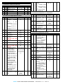
Index
1
1.1
1.2
2
2.1
2.2
2.3
2.4
2.5
2.6
3
3.1
3.2
DESCRIPTION THERMOSTAT
GENERAL DESCRIPTION
FRONT PANEL DESCRIPTION
PROGRAMMING
QUICK SELECTION SET POINT
STANDARD PROGRAMMING PARAMETERS
PROTECTED PARAMETERS BY PASSWORD
CUSTOM PROGRAMMING PARAMETERS (LEVELS OF
PROGRAMMING PARAMETERS)
RESTORE FACTORY SETTINGS
KEYBOARD LOCK FUNCTION
WARNING FOR INSTALLATION AND USE
PROPER USE
MECHANICAL ASSEMBLY
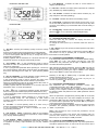
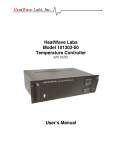
1.2 – FRONT PANEL DESCRIPTION
Front Panel F 200 / F 300
OSAKA - F 200 / F 300 / TSF 200 / TSF 300 / M3 - User Manual - V.1.2 - PAG. 1
Front Panel TSF 200 / 300
8 - Led DEFROST : Indicates the state of current defrost or
dripping state (flashing).
9 - Led FAN : Indicates the output status evaporator fan. Enabled
(On), disabled (off), inhibited (flashing).
10 - Led ALARM : Indicates the alarm status. Enables (on), off
(off), delayed or memorized (flashing).
11 - Led AUX : Indicates the status of the Auxiliary output.
12 - Led CLOCK : Indicates that the internal clock is active. If you
are in slow flashing indicates an error of the time (clock chip does
not work). If the flashing is quick indicates that the clock battery is
exhausted.
Front Panel M3
13 - Led Stand-By : Indicates that the computer is in Stand-By
(Press Key or "F" for 3 seconds or activate digital input).
2 - PROGRAMMING
2.1 - QUICK SELECTION SET POINT
Press the "SET" key and release, the display will show "SP"
alternating control value.
To change the value, press "up" to increase value and "down" to
descend.
1 – Key SET : Pressing and releasing quickly access the change
set point.
Press for 5 seconds to enter the programming mode parameter.
This mode is used to edit the parameters and to confirm the value.
It can be used together with the UP key to change the level of
programming parameters.
Pressing together with the UP button for 5 seconds when the auto
keypad lock is active, the keypad automatically unlocks.
If "Up or Down" key is held, quickly increases speed to help select
a distant value.
After selecting the desired value, is confirmed by pressing "SET" or
self confirm if no key is pressed past 10 seconds, turning the
thermostat to normal operation.
2.2 - STANDARD PROGRAMMING PARAMETERS
If the Password parameter access is not enabled (default setting),
press "SET" for 5 sec., The display will show the code that
identifies the first parameter and the "Up" or "Down" button you
2 – Key DOWN / Aux : In the programming mode is used to
can select the desired parameter.
decrease the value of the parameter to be programmed and the
selection of parameters.
After selecting the desired parameter, press the "SET" key and the
If "t.Fb" is programmed parameter allows pressing for 1 second (in
value will be programmed to the desired parameter. This setting
the normal operating mode) allows some functions as selecting the
can be changed by pressing the "Up" or "Down" to the desired
ECO mode, activating the Aux output, etc.. (See Operating DOWN
value. Press "SET" to confirm and store the value.
key).
3 – Key UP / DEFROST : In normal operating mode by pressing for
5 seconds to enable / disable a manual defrost cycle.
In the programming mode is used to increase the value of the
parameter to be programmed and the selection of parameters.
Always in programming mode can be used with the SET button to
change the level of programming parameters.
Pressing together with the SET button for 5 seconds when the
keyboard is active, to unlock the keyboard.
Returning to the "Up" or "Down" keys, is possible again select
another parameter and modify it on.
To exit the programming mode: do not touch any key for 10
seconds or press the or "F" key for 2 sec.
2.3 – PROTECTED PARAMETERS BY PASSWORD
The instrument has a parameter protection function with
configurable password in the "t, PP" parameter.
In some cases, this password is very useful so that no improper
4 - Key “
” or “F” : Pressing and releasing quickly, allowing the handling on the computer, whether to enable the password, enter
the desired number and password in the "t, PP" parameter and exit
device to display their variables (temperature measurement, etc.).
In the programming mode is used to exit the settings and return to programming.
normal operation.
If "t.UF" is programmed, allows pressing for 1 second (in the When the password is programmed, pressing "Set" for 5 seconds
normal operating mode), On / Off (Stand-by) or other control to enter the settings menu, the device displays the acronym “rP"
functions, including activating the Aux output, etc.. (See operation and pressing "Set" show "O", then with buttons "up" or "down" puts
ON / OFF key).
the correct value of password code and press "Set" to proceed to
access the programming parameters.
5 - Led SET : In normal operating mode is on when a key is If the password is correct, the display will show the code of the first
parameter. The password protection can be disabled with the
pressed, as indicative that has been pressed down.
In the programming mode is used to indicate the level of "t.PP" = oF parameter.
programming parameters.
Note: If the password is lost to access the parameters, use the
6 - Led OUTPUT - COLD : Indicates the status of the regulation following procedure:
output (compressor or control device temperature); output enabled Turn off electrical power to the device and re-feeding while you
press the "SET" button for 5 seconds. Access parameters will be
(on), off (off), inhibited (flashing).
taken and you could modify the "t.PP" parameter.
7 - Led OUTPUT - HEAT : Indicates the status of the regulation
output (resistance or device temperature control) when the action 2.4 – LEVELS OF PROGRAMMING PARAMETERS
of regulation is heating; output enabled (on), off (off), inhibited The equipment allows to password protect only certain parameters,
(flashing).
and without password others, in order to let the user access to the
OSAKA - F 200 / F 300 / TSF 200 / TSF 300 / M3 - User Manual - V.1.2 - PAG. 2
parameters needed, without access to all parameters that are 3 – WARNING FOR INSTALLATION AND USE
specific of technical or machine manufacturer.
Method to select the level of programming parameters:
3.1 – PROPER USE
The devices are made as measuring and regulating equipment in
Access programming through password and select the parameter accordance with EN EN60730-1 norm for operation up to an
to be programmed without password. If the SET LED flashes altitude of 2000 mts.
means that the parameter is programmable only with password The use of equipment for standard applications not expressly
protected, and if the LED is fixed indicates that the parameter is provided in norm cited above, should provide all measurement and
direct access without password.
adjustments necessary protection.
To modify the visibility level parameter jointly press "Set + Up" The equipment must be adequately protected and away from
keys.
liquids, dust, grease and dirt. They must be accessible only with the
use of a right tool and safety system (except the front).
The LED Set will change status, indicating the new access level The devices can NOT be used in dangerous environments
parameter (protected, flashing led) and (direct access without (flammable or explosive) without adequate protection.
password, fixed led).
It is recalled that the installer must ensure that the norm for
electromagnetic compatibility is respected after implantation in the
Upon entering the menu, the first parameters to visualize are user installation of equipment, eventually using the right filters if is
level parameters (unprotected) and then (protected) by entering the needed.
password when the computer shows "rP"
In case of failure or malfunction of measuring and control
equipment that can create dangerous situations or damage to
persons, things, animals or products (defrost food or changes in
their ideal state), it is recalled that the facility should be equipped
with electronic devices or electromechanical safety and warning
system.
They should be placed outside the measuring and control
equipments, possible protective devices, responding to specific
safety requirements that are covered by the norm of the product or
suggest the common sense.
For your own safety, is highly recommended fulfilling the
instructions provided above.
3.2 – MECHANICAL ASSEMBLY
The thermostats are designed for wall mounting or wall using the
holes in the plastic and predisposed accessible after removing the
front.
Once the equipment is installed is recommended to close the front
cover.
Avoid placing the thermostat in place exposed to high humidity or
dust, this can cause condensation or introduction of conductive
particles or substances. Ensure that the computer has adequate
ventilation and avoid installing indoor sealed boxes or areas where
2.5 – RESTORE FACTORY SETUP PARAMETERS
the temperature exceeds the specifications of the device. Avoid
The device has a mode parameter reset to factory programmed installing the cables and power supply together with the probe out
values.
and install equipment that can generate disturbances (electrical
noise) as motors, fans, inverters, automatic gates, contactors,
To return to the factory settings or default values of the parameters relays, solenoids, etc.…
is sufficient to activate the password protection and once activated
when the display set "rP" enter the password -48.
3.3 – ELECTRICAL CONNECTIONS
After confirming the password with the SET button for 2 seconds The thermostat is designed for permanent connection between
display will show "---" when the computer performs the reset of the devices, no switch is equipped with internal devices or power on
parameters, does a little testing and put all settings to default over currents or voltages. It is therefore recommended to install a
general safety thermal / isolator switch / device magneto device as
values.
close and easy access to cut if necessary, as a security . Are
reminded that you must use appropriate cable to own isolation
2.6 - KEYBOARD LOCK FUNCTION
It is possible to completely lock the keys. Such a function is useful voltage, current, temperature and local electrical codes should also
when the control is accessible to the public and you want to prevent separate the signal cables from the power probe and power as far
tampering. The key lock function is activated by setting the "t.Lo" as possible in order avoid possible electrical noise, electromagnetic
induction, which in some cases could be diminished or cancelled
parameter to a value of OF.
with RC filters, ferritic, supply, varistors, etc. ... the use of cables
The value set in parameter "T.Lo" is the time that the thermostat with antiparasitic mesh and this mesh is recommended to connect
allows access to the keyboard and after passing this time the on one side to take ground.
It is recommended to check that the equipment settings are
thermostat is locked.
appropriate to the application before connecting wires actuators,
Pressing any key displays the thermostat "Ln" to inform the lock is loads on the output relays in order to prevent malfunctions or
damage.
activated.
S.L
S.
To unlock the keyboard press "Set + Up" for 5 sec., the display will
show "LF" and all keyboard functions again become operational.
OSAKA - F 200 / F 300 / TSF 200 / TSF 300 / M3 - User Manual - V.1.2 - PAG. 3
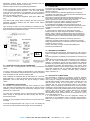
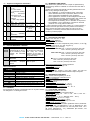
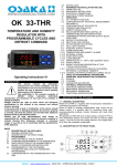
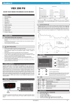
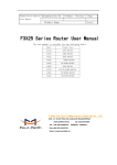
3.4 – ELECTRICAL WIRING DIAGRAM
Wiring Schema F 200 y TSF 200
Wiring Schema F 300 y TSF 300
Wiring Schema M3
D ig .
1 0 0 ...2 4 0
P r3
1
P r2
2
P r1
3
IN P U T S
4
5
VAC
IN T E R N A L
SU PPLY
BUZZER
6
7
8
NO
W 09Y
9 10 11 12
NO
NC
OUT3 OUT1
NO
C
OUT2
O U T 1 : 1 4 A -A C 1 (6 A -A C 3 ) / 2 5 0 V A C ;
1 H P 2 5 0 V A C , 1 /2 H P 1 2 5 V A C
O U T 2 : 8 A -A C 1 (3 A -A C 3 ) / 2 5 0 V A C ;
1 /2 H P 2 5 0 V A C ,1 /3 H P 1 2 5 V A C
O U T 3 : 4 A -A C 1 (2 A -A C 3 ) / 2 5 0 V A C ;
1 /8 H P 2 5 0 /1 2 5 V A C
C: 16A M AX
4 - OPERATION
4.1 – FUNCTION ON / STAND-BY
The thermostat, once fed, can make 2 states:
- ON: means that the driver is running and acting on the basis of
planned control.
- STAND-BY: means that the control does not act, stop. (The
display illuminates the LED Stand-by).
Moving from Stand-by to ON is exactly equivalent to when the
device is connected to supply. If a power failure occurs when power
returns, the system is always put in the condition that it was before
the interruption.
Mode ON / Stand-by can be selected:
- Using the key or "F" pressed for 3 sec Lets stop to change gear.
- Use the DOWN key for 3 sec If the par. "T.Fb" = 4
- Using the digital input if par. "I.Fi" = 10
4.2 – SETTINGS OF INPUTS PROBES AND DISPLAY
By the par. "I.SE" is selected if the probe you want to use is the
type KTY81 PTC-121 (Pt) or NTC 103AT-2 (nt).
With the par. "I.uP" is selected if the unit of measure to use is the
temperature in degrees Celsius (Standard) or Fahrenheit (USA)
(C0 = ° C / 1 ° (no decimal); C1 = ° C / 0.1 ° (with decimal); F0 = ° F
/ 1 °, F1 = ° F / 0.1 °).
The unit allows the calibration of the probes, which can be used for
recalibration of the equipment according to the needs of the
application through the par. "I.C1" (Pr1 entry), "i.C2" (Pr2 entry).
The par. "I.P2" to select the use of Pr2 entry, as follows:
= EP - Evaporator Probe (EP): Evaporator probe Probe (EP): the
probe functions as described below to control defrost and
evaporator fans.
= Au - Auxiliar probe (Au)
= DG – Digital Input (dG)
If the Pr2 and / or Pr3 input is not used, program it as "i.P2" and
"i.P3" = Of.
By the par. "I.Ft" it is possible to filter software on the extent of the
value of the input, so we can reduce the sensitivity and rapid
temperature change (rise time).
Through the par. "I.dS" you can set the normal display of the
display may be the measure of Pr1 probe (P1), the measurement of
the probe Pr2 (P2), the measure of Pr3 probe (P3) regulating the
Set Point active (SP), or you can still have the display off (oF).
If you see one of the measures by the par ("i.dS" = P1, P2, P3) par.
"I.CU" lets put an offset that is applied to display only the variable
(all regulatory controls are always made according to the
correct parameter measurement calibration).
Regardless of the value set in par. "I.dS" you can display all the
measured variables and rotating operation by pressing and
releasing the or "F" key.
The display will show alternately the code that identifies the
variable (see below) and its value.
The variables are as follows:
"Pr1" - Measuring probe Pr1
"Pr2" - Measuring probe Pr2
"Pr3" - Measuring probe Pr3
"Lt" - preset minimum temperature Pr1
"Ht" - Maximum temperature Pr1 memorized
The values of minimum and maximum peak Pr1 not saved to the
lack of supply and may be reset using the DOWN key, pressing it
for 3 sec. during peak viewing. After 3 seconds, the display will
show "---" for a moment and tell cancellation and taken as
maximum temperature measured at that time.
To exit the display mode of the variable will automatically in about
15 seconds after pressing the button or "F".
Note that the display of the probe Pr1 can also change the display
through the display lock function defrosting by the par. "D.dL" (see
the function. "Defrost").
4.3 – DIGITAL INPUT SETUP
The Pr2/Pr3 input (Pr2 in F200/TSF200 and Pr3 in
F300/TSF300/M3) can be configured as digital input voltage free
contact. To use the digital input must be set par. ("I.P2" = dG. On
F200/TSF200 "i.P3" = dG. On F300/TSF300/M3). The function for
that dig input will be scheduled in the "i.Fi" parameter and the
possible delay in the schedule "i.ti" parameter.
The "i.Fi" parameter or digital input can be programmed for:
= 0 – Inactive digital input (no function)
= 1 – Start defrost with contact normally open: on closing the input
(and after time "i.ti") a defrost cycle is activated.
= 2 – End of defrost with contact normally open: on closing the
input (and after the time "i.ti") the defrosting progress ends.
= 3 – Enabling Continuous cycle with contact normally open: on
closing the input (and after the time "i.ti") activates a continuous
cycle.
= 4 - Signalling of external alarm. When digital contact is closed
and after the time set in "i.ti" the display will alternately AL with the
measured temperature.
= 5 – Door opening with fan block with contact normally open: on
closing the input (and after the time "i.ti") fan stop, device shows on
display Op and alternating with the variable set in par. "I.dS". In
this mode the action of the digital input is always active after the
time set in par. "A.oA", after which the alarm is activated to signal
that the door is open and the fan OFF.
OSAKA - F 200 / F 300 / TSF 200 / TSF 300 / M3 - User Manual - V.1.2 - PAG. 4
= 6 – Door opening with fan and compressor blockade through
normally open contact: similar to "i.Fi" = 5 but with fan and
compressor block. Upon entering open door alarm also fan and
compressor stops.
= 7 – Activating auxiliary output AUX with contact normally open: on
closing the input (and after the time "i.ti") auxiliary output is
activated as described in the operating mode "i.Fo" = 2 auxiliary
output.
= 8 – Selecting the active set point SP/SP2 with contact normally
open: on closing the input (and after the time "i.ti") the set point
temperature regulation "SP2" is activated. When the input is open
the set point "SP" is active.
= 9 – Signalling of external alarm with disablement of all control
outputs with contact normally open: At the end of the entry (and
time "i.ti") comes off all control outputs, alarms are activated and
the device displays on your display alternately noF and the variable
set in the variable torque. "I.dS".
is disabled. In this mode the output can be configured as an
auxiliary off even when in automatic mode after a certain time tax
on the "o.tu" parameter.
With "o.tu" = oF the activated and deactivated manually by
pressing ("F" or ), otherwise the dismount, once activated,
automatically turns off after the set time. This operation can be
used for example to control the chamber light, anti-fog resistance or
to other utilities.
= 3 – Light up showcase and shade (function economy) connected
to "Normal/SP2" mode. The output is activated when Normal mode
is activated, whereas when in SP2 mode remains disabled.
= 4 – Internal cell light. The output remains off and turns on only if
the digital input is configured as door opening ("i.Fi" = 5.6).
The par. "O.bu" lets configure the internal buzzer (if available) as
follows:
= OF – The buzzer is disabled
= 1 – The buzzer is activated only to signal alarms
= 2 – The buzzer is activated only briefly to indicate that you have
= 10 – On / Off (Stand-by) device using normally open contact: the pressed a key (no indicates alarms)
closure of the input (and after the time "i.ti") the instrument turns = 3 – The buzzer is activated to signal alarms and when pressed a
key.
ON but when opened becomes standby mode.
= 11 – SP/SP2 active set point selection and change of action (HC) with contact normally open: on closing the input (and after the
time "i.ti") the regulation set point is activated "SP2" with action C,
when the input is open the set point "SP" is set to action H.
= -1, -2, -3, etc. – Identical functions to the above but with the
inverse logical operation (normally closed contacts).
4.4 – OUTPUTS SETUP FOR RELAYS AND BUZZER
The outputs of the device can be configured via the parameters
"o.o1", "o.o2" and "o.o3" with the following functions:
= Ot - Control compressor / solenoid or cooling element
= DF - Control of defrost heaters
= Fn - Control of evaporator fans
= Au - Output Control Assistant
= At - Allows control device Alarm "comparable" through the
normally open and closed digital input for alarm. (See section
Alarm)
= AL - Allows control device Alarm "non silenceable" through a
normally open contact closed during alarm. (See section Alarm)
= An – To control an alarm silenced through a contact normally
closed and open in alarm.
= -t – To control an alarm silenced through a contact normally
closed and open in alarm when the instrument is turned on.
The output is disabled when the device is not powered or is in
stand-by state. This mode can be used as display lighting, anti-fog
resistance or other utilities.
= -L – To control a device alarm silenced by a contact normally
closed and open in alarm.
= -n – To control an alarm device with memory function through a
normally closed and open in alarm (see alarm memory).
= on – For control of the device to be activated when connected.
The output remains off when the device is not powered or is in
stand-by. This mode can be used as a way to illuminate the display
case, anti-fog resistance or other utilities.
= oF – No function (Output Off)
If one of the outputs is configured as Auxiliary output (= Au)
function must be configured in the "o.Fo" parameter and can be
conditioned by the time set in the parameter. "O.tu". The "o.Fo"
parameter can be programmed with the following functions:
= oF – no function
= 1 – Output delay regulation.
The auxiliary output is activated by the programmed delay in the
"o.tu" parameter relative to the output configured as "ot". The
output is deactivated when the output "ot" is deactivated. This type
of operation can be used for control of a second compressor or a
parallel control that is useful for the control process. Prevents
booting two devices at once causing a high spot electricity
consumption.
= 2 – Activation by front key ("F" or ). The output is activated by
pressing the key "F" or configured as follows ("t.UF" or "t.Fb" =
1).
This setting has a bistable behavior, which means that pressing the
button the first time, the output is activated while the second pulse
4.5 – ACTIVE SET POINT SELECTION
The computer program allows 2 types of Set point adjustment ("SP"
and "SP2") and you can select which you want to activate. The
function can be used in the event that it is necessary to switch two
temperature (ex: day / night or positive / negative, etc.).
The active Set point can be selected:
-By "S.SA" parameter.
-Using the "F" / key if the "t.UF" = 3. Parameter
-Use the key DOWN / AUX if "t.Fb" = 3. Parameter
-Using the digital input if par. "I.Fi" = 8 or 11.
It is recalled that the selection of the active Set Point can be
combined with the function of the turn off Auxiliary output if used as
a light showcase and up shade (function economy) with
("o.Fo" = 3) and mode switching action Cooling / Saver for the
configured ("i.Fi" = 8) digital input.
The "SP" and "SP2" can be programmed with a value between the
value programmed on par. "S.LS" and the value set to "S.HS".
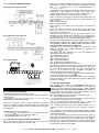
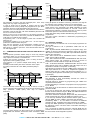
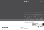
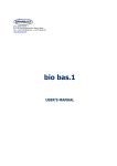
4.6 – TEMPERATURE CONTROL
In the mode of regulation of the type device ON / OFF acts over
outputs configured as "ot" and "HE" in the function of the extent of
the probe Pr1, the active Set Point "SP" (or "SP2") , the
intervention differential "rd" (or "r.Ed") and the operating mode
"r.HC".
As to the mode of operation in programmed "r.HC" the parameter
differential controller is automatically considered a positive value for
a cooling control ("r.HC" = C) or a negative value for the heating
control ("r.HC" = H).
In case that parameter comes programmed "R.HC" = nr ((NOTE !!
the option "Neutral Zone" is only available in the TSF 200
BLUE C and F 300 RT models)) the output configured as "ot"
acts with the cooling action (like "r.HC" = C) and can use a
configured as "HE" acting out the heating action.
In this case the differential regulatory intervention is automatically
considered a positive value for the cooling action and the negative
value for the heating action.
Tem p.
P r1
Tem p.
P r1
SP
r.d
r.d
SP
tim e
ON
O ut
( o t)
ON
o ff
tim e
ON
o ff
ON
O ut
( o t)
r .H C = C
OSAKA - F 200 / F 300 / TSF 200 / TSF 300 / M3 - User Manual - V.1.2 - PAG. 5
ON
o ff
r .H C = H
ON
o ff
starts).
Tem p.
P r1
r .d
SP
Tem p.
P r1
r .d
r .d
SP
tim e
O ut
(H E )
0N
0N
o ff
ON
o ff
O ut
( o t)
0N
O ut
( o t)
o ff
o ff
o ff
P .P 3
All protections set time in the next paragraph (P.P1, P.P2, P.P3)
always and only output configured as "ot".
In case of probe error is possible to perform that the output
configured as "ot" works cyclically time programmed on par. "R.t1"
(activation time) and "r.t2" (deactivation time) during error.
When an error occurs the probe Pr1, the instrument comes with the
activation of the "ot" exit time "r.t1" when disabled by the time "r.t2"
and so on if the error remains.
When an error occurs in the probe Pr1, the device proceeds to
activate the output "ot" for time "r.t1", proceeds to disable the time
"r.t2" and so on while the error remains.
Programming "r.t1" = oF the output in probe error condition will
always be off.
Programming instead of "r.t1" any value "r.t2" = oF the output in
probe error condition will be always on.
Note that the operation of the temperature controller may be
subject to the following function: "Protection of compressor and
delay timer to" "defrost" open door "and" external alarm with lock
out "with digital input.
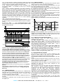
4.7 – COMPRESSOR PROTECTION FUNCTION AND DELAY TO
START
The compressor protection feature helps to avoid very frequent
compressor starts or it can also be useful for control in time for the
relay output to an actuator or intended load.
Activate this function provides 3 types of timing choices as
appropriate to the regulatory system.
The protection is to prevent multiple starts during the time of
protection.
The first provides a delay time to the activation of the output
according to the time set in the "P.P1" parameter (delay to
start).
Tem p.
P r1
r .d
SP
ON
O ut
( o t)
o ff
ON
ON
o ff
o ff
t im e
o ff
The second time, foresee a delay on relay of control, in order to
ensure a minimum time between the arrest and the progress of the
relay parameter: "P.P2" (delay after stop or minimum
downtime).
Tem p.
P r1
r .d
SP
ON
O ut
( o t)
ON
ON
o ff
o ff
P .P 2
P .P 2
tim e
o ff
P .P 2
The third period foresee not allow starts if has not exceeded the
programmed time between consecutive starts. Parameter "P.P3"
(delay
after
consecutive
ON
ON
o ff
P .P 3
tim e
o ff
P .P 3
During all phases of inhibition caused by protection, LED signals
the activation of the regulation output (Cool or Heat) flashing.
You can also activate a delay to the start of the regulation when
power arrives to the thermostat. The "P.od" parameter is useful
when there are multiple thermostats, for not start loads at the
same time and allowing a smoother power line or protect to power
failures that prevent no discontinuous starts booting.
During this phase delay visualize od alternating the normal viewing
programmed.
The timer function described is deactivated programming the
parameter = oF.
4.8 – DEFROST CONTROL
The control mode for defrosts acts on the output programmed as
"ot" and "dF".
The type of defrost is set in parameters "d.dt" that can be
programmed:
= EL – By ELECTRICAL RESISTANCE (or compressor stop): This
modality in defrost mode has the compressor output "ot" off, while
"dF" output is activated. Not using "dF" output will obtain defrost by
stopping the compressor.
= in – HOT CYCLE GAS or INVERSION CYCLE: during defrost,
output "ot" and "df" are enabled.
= no – NO FUNCTION OUTPUT COMPRESSOR: With this mode,
during defrost output "ot" continues to work as a function of
temperature controller while the output "dF" is activated).
= Et – ELECTRIC DEFROST THERMOSTATED: With this mode
during defrost output "ot" is disabled, while "Df" output acts as a
temperature controller of evaporator on defrosting.
This selection is end defrost by time ("d.De"). During defrosting, the
"Df" output behaves as a control for temperature regulation, in
heating mode with Set = "d.Te" and with fixed hysteresis of 1 º C
and cooling the temperature measured by the evaporator probe set
to probe (EP).
4.8.1 – AUTOMATIC START DEFROST
The defrosting is done automatically because the device is
configured by time intervals.
Automatic defrost is obtained by programming par. "D.Di" time
required between defrosts.
The first defrosting to connection of equipment can be programmed
in par. "D.Sd".
This allows to do the first defrost on different interval seted in the
parameter "D.Di".
If you want on device start, this perform a defrost cycle (provided
that the conditions stated in the par. "D.tS" and "d.tE" indicated and
described below) program the par. "D.Sd" = oF.
This allows defrost the evaporator always when they have frequent
power outages that may cause cancellations in defrost cycles.
If you wish only standard rhythms between defrost cycles, set the
value of "d.Sd" to value = "D.Di" to cancel the start defrosting.
Establishing "D.Di" = oF, the defrost at intervals are disabled
(including the first, regardless of the time imposed in par. "D.Sd".
Through the "d.Dc" parameter is possible to set the mode of how
the defrosting is done. The start mode of automatic defrosting is
described below:
= rt – At intervals of real-time connection. Intervals "D.Di" are the
account total time since the device turns on. This method is one of
the more used in most refrigeration systems.
OSAKA - F 200 / F 300 / TSF 200 / TSF 300 / M3 - User Manual - V.1.2 - PAG. 6
= ct – At time intervals of working compressor. Adding the partial
operation times every X hours working will perform a defrost. This
mode is used only in facilities positive temperature cold.
= cS – (atypical special regulation) to each compressor stop.
Programming ("D.Di" = oF, defrosting is done only on stop the
compressor).
= St – Defrost evaporator temperature. The device activated a
defrost cycle when the evaporator temperature (probe set to EP)
amounts below the value set in the parameter. "D.tS" or the end of
time programmed in rt mode (if "D.Di" = oF defrost always done by
evaporator temperature) This system can be used to defrost the
evaporator used machinery such as pumps heat (in this case
defrosting time intervals would be disabled) to ensure defrost if the
evaporator temperature reaches well below that normally results
symptoms of low thermal change from the normal operating
conditions.
= dd – DYNAMIC REDUCTION DEFROST
This parameter is used in the so-called "Dynamic Defrost" in which
the device reduces the time between defrosts if system conditions
require.
By parameter "d.dd" = 0 .. 100% (recommended 25% to 50%
values) program "%" to be reduced if the system requires cutting
the time between defrosts.
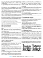
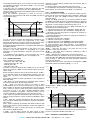
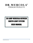
4.8.3 – END OF DEFROST
The defrost cycle can be time consuming if the evaporator probe
(probe set to EP) is used to achieve the temperature.
In case that it can not use the evaporator temperature, the cycle
time will be established by the par. "D.dE".
If the evaporator temperature is used, the end of defrosting is when
the temperature measured by this probe set to EP exceeds the
temperature set by the torque. "D.tE".
If this temperature is not reached within the time fixed by the par.
"D.dE" defrost does not terminate.
So if the temperature measured by the evaporator probe is higher
than that imposed in par. "D.tE" defrosting is inhibited.
The defrost cycle is indicated by the led DEF. At the end of defrost
to delay the restart of the compressor (output "ot") time set in par.
"D.td" to allow the evaporator drip.
During this delay, the LED blinks to indicate DEF status finish drip.
Tem p.
EP
d .tE
ON
ON
tim e
Tem p.
dF
o ff
A
o ff
B
o ff
C
d .tE
d .d E
d .d i/d .S d
P r1
d .d i
( N O d e fr o s t)
d .d i
d .d i
EP
S P + r.d
r.d
SP
DT0
DT1
DT2
DT3
1
2
3
Example of end of defrost: Defrost indicated as "A" ends up
reaching the temperature "d.tE", the "B" part ends at the end of
"d.dE" in terms of tempera "d.tE" is reached, the defrost "C" does
not work when the temperature is above "d.tE".
1 °
d .tS
P hase
C ool
(o t)
0
ON
ON
o ff
d .d i / d .S d
ON
o ff
tim e
ON
o ff
tim e to d e fro s t P h . 0 , 1
tim e to d e fro s t P h . 2
tim e to d e fro s t P h . 3
D e fro s t
(d F )
D e fro s t
Operation Example "dynamic defrost system intervals" with
reduction "d.dd" = 30% and end defrost temperature.
The system anticipates the accumulation of ice leaving the battery
in peak condition. This function operates when the output of cold is
turned on and the temperature of the camera is in the Set Point +
rd / 2, if the difference between the temperature of the chamber
and the evaporator exceeds the reference value DT0 by 1 ° C or
more, and the difference between the evaporator and chamber is
superior to the last comparison, reduces the "d.dd" programmed
value on time "d.di" or "d.Sd". To use this system it is
recommended that the "d.di" parameter enter the longest possible
time taking into account the proper functioning of the system. The
advantage of defrosting at intervals is that it allows dynamic
scheduling intervals longer than normal and defrost work so they
are system conditions that determine whether the anticipated
implementation defrost if necessary.
If the set time is too short you may not have time to act "Dynamic
Defrost".
If the system is configured correctly, you manage to avoid many
UNNECESSARY defrost and as a result ... Energy Saving and
Efficiency.
4.8.2 – MANUAL DEFROST
To activate a manual defrost cycle press the UP / DEFROST key
while the device is in operation and hold down for 5 seconds. If
conditions are optimal for defrosting will be conducted, either
evaporator probe par. "D.te" and "d.ts".
To cancel a defrost proceed to press UP / DEFROST button for 5
seconds.
The activation commands / stop of a defrost cycle can also be via
the digital input.
4.8.4 - DISPLAY LOCK ON DEFROST MODE
Using parameters "d.dL" and "A.Da" display behavior is
established during defrosting.
The "d.dL" parameter causes blocking last temperature on the
display before defrost ("d.dL" = on) until you reach the end of
defrost and the temperature does not exceed below the value of the
final temperature memorized or the condition ["SP" + "r.d"], or
exceeds the safety time lock "A.Da".
Also allows visualization of the indicative initials Defrost "dEF" ("dl"
= Lb) and after defrost the acronym "PdF" that indicates time
defrost finish but cold temperature not recovered to control value
["SP" + "r.d"]) or exceeds the safety time lock "A.Da".
Another possibility is to indicate the actual temperature of the cold
chamber or cabinet, during defrosting ("d.dL" = oF).
4.9 - EVAPORATOR FAN CONTROL
The evaporator fan control works for output configured as "Fn"
function in certain states of the device and the temperature
measured by the evaporator probe (probe set to "EP").
The parameters related to the fan control functions are in the " Fn"
folder.
In the event that the evaporator probe is not used or is in error, the
output configured as "Fn" is activated only in function of the
parameters "F.tn", "F.tF" and "F.FE".
Using parameters "F.tn" and "F.tF" you can set the behavior of the
evaporator fan when the control output configured as "ot"
(compressor) is switched off.
When the output "ot" is off may cause the output configured as
"Fn" continue to operate cyclically according to the times
programmed in the "Ftn" parameter (activation time fan evaporator
compressor off) and "F.tF" (time deactivation evaporator
compressor off) fan. By stopping the compressor equipment
evaporator fan can keep ignition time "F.tn", and disable the time
"F.tF" when output "ot" remains disabled. Programming "F.tn" Fn =
oF the output is turned off by stopping the output "ot" (evaporator
fan off stopped functioning compressor or fan attached to the
compressor).
Programming "F.tn" to any value and "F.tF" = oF the "Fn" output
will remain active also disabling the output ot (active compressor off
evaporator fan).
OSAKA - F 200 / F 300 / TSF 200 / TSF 300 / M3 - User Manual - V.1.2 - PAG. 7
The "F.FE" parameter allows you to set if the fan has to be always
on regardless of the state of the defrost ("F.FE" = on) or off during
defrosting ("F.FE" = oF).
In the latter case it is possible to delay the restart the fan after
completing defrosting, for the time set in the "F.Fd" parameter.
When this delay is activated the LED flashing FAN is set to indicate
the delay in progress.
When the evaporator temperature is used for the fan, is
conditioned by the parameters "F.tn" "F.tF" and "F.FE", and acts as
a temperature control.
Tem p.
EP
F .F L
F .d F
F .d F
F .L F
ON
Fn
o ff
ON
o ff
t im e
o ff
You can set the fan off when the temperature measured by the
evaporator probe is higher than programmed in the "F.FL"
parameter (temperature too high) or where it is less than the value
programmed in the "F.LF" parameter (very low temperature).
Associated with these parameters is a programmable differential in
the "F.dF" parameter.
Note: You must pay special attention to the proper use of the
functions of fan control based on temperature as a typical
application of a typical refrigeration evaporator fan stops for heat
exchange.
It is recalled that the operation of the evaporator fan can be
conditioned to the "open door" function of the digital inputs.
4.10 – ALARM FUNCTIONS
Alarm conditions controllers are:
- Probe Error: "E1", "-E1", "E2," -E2"
- Temperature alarm: "Hi", "Lo"
- External alarm "AL"
- Alarm door open: "oP"
The alarm function is displayed the ALARM LED on the internal
buzzer, set by the par. "O.bu" or on the desired output is set by par.
"O.o1" "o.o2".
Buzzer sounds on alarm but can be disconnected the par. "O.bu" =
1 or 3, and after ringing can be deactivated by pressing a key. The
alarm output can point to the following schedule settings of the
output.
The possible selection of these parameters for the operation of
alarm signal are:
= At – When you want the output to be activated in alarm condition
and can be turned off (by keypad alarm) manually.
= AL – When you want the output to be active in alarm
CONDITION but can not be turned off manually or is only when the
alarm condition is cancelled. (Typical Application one bright signal).
= An – When you want the output to be active in alarm conditions
and keeps on even if the alarm condition disappears (alarm
memory) Deactivation (recognition memorized alarm) can be
removed manually by pressing any key when the alarm is over.
= -At – When the operation described as "At" with inverse logic is
desired. (output activated in normal condition and disabled in alarm
status).
= -AL – When the operation described as "AL" but with function
logic reversed is desired.(output activated in normal and disabled in
alarm status)
=-An – When considering the operation described as "An" but with
inverse logic operation (output activated in normal and disabled in
alarm status)
The unit has the option of having the function of activating the
alarm memory "A.tA" parameter.
If "A.tA" = Of the device cancels the alarm signal to alarm
conditions cease, but if programed = On alarm conditions are also
recorded but keeps flashing ALARM LED and indicates that an
alarm was verified.
To cancel the alarm memory signaling just press any key.
It is recalled that if the operation of a memory alarm output (o = AnAn) is desired, you must program the "A.tA" = on parameter.
4.10.1 – ALARM FUNCTIONS
The alarm function is a function of temperature reading from the
probe, and the type of programmed alarm, parameter. "A.Ay" and
the alarm set point, par. "A.HA" (maximum alarm) and "A.LA"
(minimum alarm).
Through the "A.Ay" parameter you can specify whether the alarm
set "A.HA" and "A.LA" should be considered absolute or relative to
the active Set Point, whether to display in the message display Hi
(High alarm ) or Lo (low alarm) when entering alarm or not.
Depending on the operation by the par "A.Ay" considered can be
programmed with the following value:
= 1: Absolute reference to Pr1 with visualization. Display (Hi - Lo)
= 2: Relative with reference to Pr1 visualization. Display (Hi - Lo)
= 3 Absolute concerning the probe Pr2 configured as "ancillary" to
display. Display (Hi - Lo)
= 4: Relative reference to the probe Pr2 configured as "ancillary" to
display. Display (Hi-Lo)
= 5: Absolute concerning Pr1 no display
= 6: Relative concerning Pr1 no display
= 7: Absolute reference to the "auxiliary" probe without display
= 8: Relative reference to the "auxiliary" probe without display
By some parameters may delay activation, if the situation is
cancelled recovering optimal conditions, without becoming alarm.
These parameters are:
“A.PA” – delay time the alarm to get power and turn on the
regulation, in case you are in alarm.
“A.dA” – time delay after a defrost (A. maximum) or after a
continuous cycle (A. Min).
“A.At” – delay time of the performance of temperature alarm.
Temperature alarms are enabled at the end of exclusion time and
is activated after the "A.At" when the temperature measured by the
probe exceeds or falls below the alarm thresholds respective
maximum and minimum.
The differential alarm will be the same set in parameters "A.HA"
and "A.LA" if alarms are absolute ("A.Ay" = 1, 3, 5, 7).
Tem p.
A .H A
1°
1°
A .L A
ON
AL
o ff
Hi
ON
o ff
Lo
t im e
o ff
Or values ["SP" + "A.HA"] and ["SP" + "A.LA"], if alarms are relative
("A.Ay" = 2, 4, 6, 8).
Tem p.
1°
A .H A
SP
A .L A
1°
ON
AL
o ff
Hi
ON
o ff
Lo
t im e
o ff
Temperature alarms maximum and minimum may be switched off if
we put in on parameter "A.HA" and "A.LA" = oF.
4.10.2 – EXTERNAL ALARM DIGITAL INPUT
OSAKA - F 200 / F 300 / TSF 200 / TSF 300 / M3 - User Manual - V.1.2 - PAG. 8
The device can signal an external alarm in device by activating the
digital input with the function programmed as "i.Fi" = 4 or 9.
Contemporaneously with the signaling configured alarm (buzzer
and / or output), the device signals the alarm by activating the
ALARM LED display and its display label AL alternately with the
variable set in par. "I.dS".
The mode "i.Fi” = 4 does not operate with no action on the control
output, while the mode "i.Fi" = 9 provides disabling all control
outputs in the intervention of the digital input.
4.10.3 – OPEN DOOR ALARM
The device may signal a door alarm by activating the digital input
with the function programmed as "i.Fi" = 5 or 6.
In activating the digital input the device indicates that door is open
through viewing the display oP alternately with the variable set in
parameter label. "I.dS".
After the delay programmed in par. "A.oA" the device notes the
alarm through the activation of the configured device (buzzer and /
or output), activating the ALARM LED is continuous with message
display oP.
The intervention of the open door alarm is also reactivated when
the output is inhibited (fan + fan or compressor).
4.11 – OPERATION OF KEY “F” /
AND “DOWN / AUX”
The key "F" or
is defined by the "t.UF" parameter while the
keyboard function "DOWN / AUX" can be defined by the "t.Fb" the
two parameter included in settings "t".
Both parameters have the same possibilities and can be configured
for the following functions:
= OF - No Function
= 1 - Pressing the button for at least 1 second to turn on / off the
auxiliary output from configuring ("o.Fo" = 2) parameter.
= 2 - Press the button for at least 1 second to enable / disable a
continuous cycle.
= 3 - Pressing the button for at least 1 second, one of 2 set point
stored in rotation is selected. After selection, the display will flash
for approximately 1 second showing the value of the active set
point (SP or SP 2)
= 4 - Press the button for at least 1 second instrument status from
on to standby and vice versa is changed.
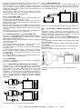
4.12.2 – REMOTE VIEWING "X2"
The device is possible to connect a remote display device via a
cable X2 can be up to 10 m start. The X2 device is powered directly
from equipment, displays temperature measured by the probe Pr1
by a 2-digit display and a half.
SU PPLY
c a b le 1 0 m M A X .
X2
TVR Y
Refer to the user manual regarding X2 device for more information.
4.12.3 - RS485 SERIAL COMMUNICATION WITH "CONV-TTL
RS"
Through RS CONV-TTL device can connect the device to your
computer to a network serial RS485 that are integrated into other
equipment (controller or PLC) and is directed to a personal
computer used as plant supervisor communication.
The protocol software is suited to computer MODBUS RTU type
widely used in several PLC and supervision programs available on
the market.
If the equipment is used with CONV-TTL RS, program par. "T.Ad"
device management.
Therefore put in this parameter, a different number than the others,
from 1 to 255.
The transmission speed (baud-rate) series is not adjustable and is
fixed at 9600 baud.
CONV-TTL converter RS is powered directly from your device.
4.12 - ACCESSORIES
The device is equipped with a 5-pin connector for connecting an
accessory described below.
4.12.1 – CONFIGURATION PARAMETERS WITH “USB KEY”
The device has a connector that allows you to transfer the
operating parameters from the "KEY USB" device equipped with a
5-pin connector. The "KEY USB" device is used for serial Consult the user manual on the CONV-TTL RS device for more
programming of devices must have the same configuration information.
parameters, or to save a copy of the programming device and to
transfer it quickly. The device has a USB input, allowing connection
to a PC, with which, through the software configuration "Universal
Conf" or "Osaka Set Up" is possible to configure operating
parameters.
SU PPLY
USB
KEY USB
USB
SU PPLY AD APTER
12 VDC
AC SU PPLY
For more information, see the "KEY USB" device manual.
OSAKA - F 200 / F 300 / TSF 200 / TSF 300 / M3 - User Manual - V.1.2 - PAG. 9
5 – PROGRAMMABLE PARAMETERS LIST
“S” parameters relative to the Set Point.
Par.
Description
Range
1 S.LS Minimum Limit Set
-99.9 ÷ HS
Point
2 S.HS Maximum Limit Set
LS ÷ 999
Point
3 S.SA Active Set Point
1÷2
4 SP Set Point 1
S.LS ÷S.HS
5 SP2 Set Point 2
S.LS ÷ S.HS
“i” Parameters for Digital Input and Probes
Par.
Description
Range
6 i.SE Type of probe
Pt - nt
7 i.uP Unit of measure and C0 / F0 / C1 /
resolution
(decimal
F1
point)
C0 = ° C with
resolution 1 °
F0 = ° F with resolution
1°
C1 = ° C with 0.1 °
resolution
F1 = ° F with 0.1 °
resolution
8 i.Ft Measuring filter
oF ÷ 20.0
sec
9 i.C1 Calibration probe Pr1
-30 ÷ 30
(chamber)
°C/°F
10 i.C2 Calibration probe Pr2
-30 ÷ 30
(Evaporator)
°C/°F
11 i.C3 Calibration probe Pr3
-30 ÷ 30
(Auxiliary)
°C/°F
*Only for F 300 / TSF
300 / M3
12 i.CU Visualization Offset
-30.0 ÷ 30.0
°C/°F
13 i.P2 Probe function Pr2
oF – EP – Au –
dG
14 i.P3 Probe function Pr3
oF – dG – Au –
Ep
*Only for F 300 / TSF
300 / M3
15 i.Fi Digital Input function:
-11/-10 / -9 / -8
0 = No function
/ -7 / -6 / -5 / -4
1= Start of defrost
/ -3 / -2 / -1 / 0 /
2= End of defrost
1/2/3/4/5/
3= Continuous Cycle
6 / 7 / 8 / 9 / 10
4= External Alarm
/11
5= Open door with lock
fan
6= Open door with lock
fan and Cold / Heat
7= Activation Auxiliary
output
8= Active Set Point
Selection (SP-SP2)
9= External Alarm with
control output
deactivation
10= Start/Stop (Standby)
11= Active Set Point
Selection (SP-SP2)
with inversion of
control (HC)
16 i.ti Actuate delay function oF ÷ 0.01 ÷
programmed on digital 9.59 (min.sec)
input.
÷ 99.5
(min.sec)
Def.
-50.0
Note
99.9
1
0.0
0.0
Def.
nt
C1
2.0
0.0
0.0
0.0
0.0
oF
oF
0
oF
Note
17 i.dS Variable shown on the P1 - P2 - P3 display:
SP - oF
P1 = Chamber Probe
Pr1
P2 = Evap. Probe Pr2
P3 = Auxiliary Probe
Pr3
SP= Active Set Point
oF = Display Off
“r” Parámetros de Regulación de Temperatura
Par.
Description
Range
18 r.d Differential
0 ÷ 30
(Hysteresis) regulation
°C/°F
19 r.t1 Activation
of
the oF ÷ 0.01 ÷
compressor relay if 9.59 (min.sec)
defective sensors.
÷ 99.5
(min.sec)
20 r.t2 Stop time of the oF ÷ 0.01 ÷
compressor relay if 9.59 (min.sec)
defective sensors.
÷ 99.5
(min.sec)
21 r.HC Operating mode:
H–C
H = Heat (heat)
C = Cool (Cool)
22 r.tC Continuous
cycle oF ÷ 0.01 ÷
duration (Turbo frost).
9.59 (h.min) ÷
99.5 (h.min)
“d” parameters management "Defrost"
Par.
Description
Range
23 d.dt Type of defrost:
EL / in / no / Et
EL = Electric defrost or
compressor stop
In = hot gas defrost /
reverse cycle
no
=
compressor
maintains regulation
Et = thermostatic
evaporator defrost
24 d.di defrost interval
oF ÷ 0.01 ÷
9.59 (h.min) ÷
99.5 (h.min)
25 d.Sd Delay of defrost at oF ÷ 0.01 ÷
start
9.59 (h.min) ÷
(oF = Allows defrost at 99.5 (h.min)
start)
26 d.dE Maximum duration of oF ÷ 0.01 ÷
defrost
9.59 (min.sec)
÷ 99.5
(min.sec)
27 d.tE Defrost
end - 99.9 ÷ 999
temperature
°C/°F
28 d.tS Activation temperature - 99.9 ÷ 999
defrost
°C/°F
29 d.dC Trigger Mode
rt / ct / cS / St /
rt = a whole time
dd
intervals
ct = time interval for
compressor operation
cS = Defrost at each
compressor stop
St = Automatic Defrost
Evaporator
Temperature (d.tS)
dd = Defrost a dynamic
range
30 d.dd Defrost in dynamic
0 ÷ 100
range
31 d.td Compressor
delay oF ÷ 0.01 ÷
after defrost (drip)
9.59 (min.sec)
÷ 99.5
(min.secx10)
OSAKA - F 200 / F 300 / TSF 200 / TSF 300 / M3 - User Manual - V.1.2 - PAG. 10
P1
Def.
2.0
Note
oF
oF
C
oF
Def.
EL
6.00
6.00
20.0
8.0
2.0
rt
50
oF
Note
32 d.dL Display
block
in
defrosting.
oF = Displays actual
temperature.
on = Displays the last
measure
Lb = Displays "dEF"
defrosting and "PdF"
oF - on - Lb
“F” Evaporator Control Parameters (Fans)
Par.
Description
Range
33 F.tn Activation of the
oF ÷ 0.01 ÷
evaporator fan
99.5
compressor off
34 F.tF Deactivation
time oF ÷ 0.01 ÷
compressor evaporator
99.5
fan running
35 F.FL Maximum temperature - 99.9 ÷ 999
for blocking fan (PR2)
°C/°F
36 F.LF Minimum fan blocking - 99.9 ÷ 999
temperature (PR2)
°C/°F
37 F.dF Fan differential lock
0 ÷ 30
°C/°F
38 F.FE State
fan
during
oF – on
defrost
39 F.Fd Fan delay after defrost
oF ÷ 0.01 ÷
9.59 (min.sec)
÷ 99.5
(min.sec)
“P” Compressor Protection Parameters
Par.
Description
Range
40 P.P1 delay to start
oF ÷ 0.01 ÷
99.5
41 P.P2 Delay after stop or oF ÷ 0.01 ÷
minimum downtime
99.5
42 P.P3 Delay
after
the oF ÷ 0.01 ÷
consecutive starts
99.5
43 P.od Delay compressor start oF ÷ 0.01 ÷
to
energizing
the 9.59 (min.sec)
instrument.
÷ 99.5
(min.sec)
“A” Alarm Configuration Parameters
Par.
Description
Range
44 A.Ay Temperature
alarm 1 / 2 / 3 / 4 / 5 /
type:
6/7/8
1 = Absolute probe
"Pr1" with visualization
display (Hi - Lo)
2 = Relative probe
"Pr1" with visualization
display (Hi - Lo)
3 = Absolute probe
"Au" with visualization
display (Hi - Lo)
4 = Relative probe
"Au" with visualization
display (Hi - Lo)
5 = Absolute for "Pr1"
no display on display
6 = Relative to "Pr1"
without viewing display
7 = Absolute probe
"Au" display no display
8 = Relative probe
"Au" no display on
display
45 A.HA Set Point alarm for oF / - 99.9 ÷
high temperature
999 °C/°F
46 A.LA Set Point alarm for low oF / - 99.9 ÷
temperature.
999 °C/°F
47 A.Ad Differential
0 ÷ 30
temperature alarm.
°C/°F
oF
48 A.At Temperature alarm
delay
49 A.tA
50 A.PA
51 A.dA
Def.
5.00
Note
52 A.oA
oF
2.0
-50.0
1.0
on
oF
Def.
oF
Note
oF
oF
oF
Def.
Ab
Note
oF ÷ 0.01 ÷
9.59 (min.sec)
÷ 99.5
(min.sec)
Memory alarm.
Off-on
Alarm on delay at start
oF ÷ 0.01 ÷
9.59 (h.min) ÷
99.5 (h.min)
Delay of temperature oF ÷ 0.01 ÷
alarm after defrost, 9.59 (h.min) ÷
defrost lock display.
99.5 (h.min)
Open
door
alarm oF ÷ 0.01 ÷
delay.
9.59 (min.sec)
÷ 99.5
(min.sec)
oF
off
2.00
1.00
3.00
“o” - Buzzer Outputs and Configuration Parameters
Par.
Description
Range
Def.
53 o.o1 OUT1
relay
oF/ot/dF/
ot
configuration:
Fn/Au/At/
oF = no function
AL/An/ -t/ -L/ ot
=
Control
n/on
temperature
(compressor
or
solenoid)
dF = Defrost
Fn = Fan
Au = Auxiliary
A /-tt = Alarm Silenced
AL /-L = Alarm not
muted
An /-n = preset alarm
on = output activated
when the device is
running
54 o.o2 OUT2
relay
oF/ot/dF/
dF
configuration: Similar
Fn/Au/At/
"o1".
AL/An/ -At/ AL/ -An/on
55 o.o3 OUT3
relay
oF/ot/dF/
Fn
configuration: Similar
Fn/Au/At/
"o1".
AL/An/ -At/ AL/ -An/on
*Only for F 300 / TSF
300 / M3
56 o.bu buzzer operation
oF / 1 / 2 / 3
3
oF = off
1 = only for alarm
2 = keypad sound only
3 = enabled alarm and
keyboard
*Only for F 300 / TSF
300 / M3
57 o.FO Operating
mode oF / 1 / 2 / 3 / 4
oF
auxiliary relay output
oF = No Function
1 = Check Out delayed
2 = Manual activation
of keyboard or In. Dig.
3 = cabinet light with
economy
feature
(enabled with "SP"
standing with "SP2")
4 = internal light (door
stop)
58 o.tu Time relative to the oF ÷ 0.01 ÷
oF
auxiliary output.
9.59 (min.sec)
÷ 99.5
(min.sec)
OFF
OFF
1.0
OSAKA - F 200 / F 300 / TSF 200 / TSF 300 / M3 - User Manual - V.1.2 - PAG. 11
Note
“t” – Keyboard Configuration Parameters
Par.
Description
Range
59 t.UF Operation mode key oF / 1 / 2 / 3 / 4
"F" (U)
oF = No Function
1 = Command auxiliary
output
2
=
Command
Continuous Cycle
3 = Active Set Point
Selection
4 = Start / Stop (Standby)
60 t.Fb Down key operating oF / 1 / 2 / 3 / 4
mode / Aux: see "t.UF"
61 t.Lo Automatic keypad lock. oF ÷ 0.01 ÷
9.59 (min.sec)
÷ 30.0
(min.sec)
62 t.PP Password access to
oF ÷ 999
the
operating
parameters.
63 t.AS Device address for
0 ÷ 255
serial communication
MODBUS
Def.
4
Note
oF
oF
oF
6.3 – WARRANTY AND REPAIR
This device has a guarantee in form of repair or replacement by
manufacturing defects in materials of 12 months from the date of
purchase.
OSAKA SOLUTIONS automatically void this guarantee and is not
liable for any damages deriving from:
- Use, installation, or use and handling undue, others than
those described above and, in particular, differs from the
safety requirements established by the regulations.
- Use in applications, machines or electrical panels that do not
provide adequate protection against liquids, dust, grease and
electric shocks to the installation conditions made.
- The inexperienced handling, and / or alteration of the product.
- The installation / use in applications, machines or electrical
panels do not comply with the valid norm.
In case of defective product under warranty or out of that period, it
should contact the post sales service to perform the necessary
steps. Request document repair "RMA" (by mail or fax) and
complete it, is necessary send the RMA and the device to SAT
OSAKA by method prepaid.
7 – TECHNICAL DATA
1
6 – TROUBLESHOOTING, MAINTENANCE AND WARRANTY
6.1 – FAILURE WARNINGS / ERRORS
Error
Reason
Action
E1-E1 The probe can be Check the connection of
E2-E2 interrupted (E) or short (- the probe to the instrument
E3-E3 E), or measuring a value and verify the correct
outside the allowable operation of the probe. (it
range.
helps to have the values of
the probes ohms)
Possible anomaly in Press Set button
Epr
EEPROM
Memory
error Replace the product or
Err
irreversible,
disrepair sent for repair
device
Otras indicaciones:
Display
Reason
Indicator
Delay-start after power equipment
od
keypad Locked
Ln
High temperature alarm in progress
Hi
Low temperature alarm
Lo
Digital input alarm in progress
AL
open door
oP
Active defrost, indication if "d.dL" = Lb
dEF
Defrost finish recovering cold if "d.dL" = Lb
PdF
Continuous cycle in progress.
CC
7.1 – ELECTRICAL FEATURES
Supply: 100...240 VAC +/- 10%
Frequency AC: 50/60 Hz
Consumption: 3 VA APROX.
Inputs /i: 3 inputs for NTC temperature probe (103AT-2, 10 K Ω @
25 °C) or PTC (KTY 81-121, 990 Ω @ 25° C)
Relays Outputs: Up to 3 Relays
F 200 / TSF 200: OUT 1: 16A-AC1 (9A-AC3) / 250 VAC
OUT 2: 8A-AC1 (3A-AC3) / 250 VAC
F 300 / TSF 300: OUT 1: 16A-AC1 (9A-AC3) / 250 VAC
OUT 2: 8A-AC1 (3A-AC3) / 250 VAC
OUT 3: 5A-AC1 (2A-AC3) / 250 VAC
M3: OUT 1: 14A-AC1 (6A-AC3) / 250 VAC
OUT 2: 8A-AC1 (3A-AC3) / 250 VAC
OUT 3: 4A-AC1 (2A-AC3) / 250 VAC
Relay Output Electrical life: 100000 operations
Power supply: EN 60730-1 type 1.B
Overvoltage Category: II
Device Class: Class II
Insulation: (power 115/230 V and relay output); and part low
voltage inputs; Electrically isolated between output and power
7.2 – MECHANICAL FEATURES
Body: Plastic self-extinguishing UL 94 V0
Category of resistance to heat and fire: D
Weight: 115 g approx.
Connection: Terminal block 2,5 mm2
Pollution Degree: 2
Ambient operating temperature: 0 ... 50 ° C
Operating humidity: 95HR% no condensing
Storage and transport temperature: -25 ... 60 ° C
6.2 - CLEANING
Se recomienda de limpiar el Termostato solo con un paño húmedo 7.3 – FUNCTIONAL FEATURES
sin detergente o con detergente neutro.
Temperature regulation: ON / OFF
Defrost control: interval for compressor failure.
Measuring range: NTC: -50 ... 109 ° C / -58 ... 228 ° F; PTC: -50 ...
150 ° C / -58 ... 302 ° F
Display resolution: 1 ° or 0.1 ° (between -99.9 ... 99.9 °)
Total accuracy: + / - (0.5% FS + 1 digit)
Time measured speed (no filter): 130 ms
Display: 3 Digits Reds (optional Blue) h 15.5 mm
Software class structure: Class A
Compliance: Directive 2004/108/EC (EN55022 class B, EN610004-2: 8KV air, 4KV cont; EN61000-4-3. 10V / m, EN61000-4-4: 2KV
power, inputs, outputs; EN61000-4-5: com 2KV power mode, 1 kV \
diff mode, EN61000-4-6:.. 3V), 2006/95/EC (EN 60730-1, EN
60730-2-7, EN 60730-2 -9)
OSAKA - F 200 / F 300 / TSF 200 / TSF 300 / M3 - User Manual - V.1.2 - PAG. 12
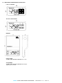
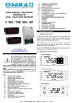
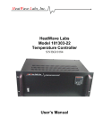
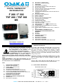
7.4 – MECHANICAL DIMENSION AND SUBJECTION
F 200 / F 300 Model
TSF 200 / TSF 300 Model
M3 Model
HOLES PANEL
- F 200 / F 300 / TSF 200 / TSF 300: 29 x 71 mm
ATTACHMENT
- F 200 / F 300 / TSF 200 / TSF 300: Side Clamps
- M3: Surface via screw
OSAKA - F 200 / F 300 / TSF 200 / TSF 300 / M3 - User Manual - V.1.2 - PAG. 13
OSAKA - F 200 / F 300 / TSF 200 / TSF 300 / M3 - User Manual - V.1.2 - PAG. 14