1
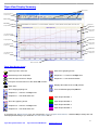
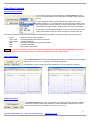
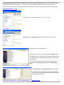
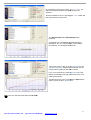
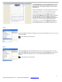
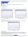
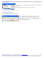
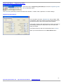
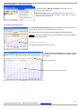
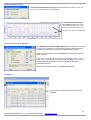
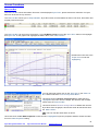
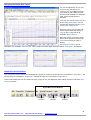
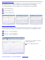
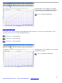
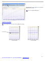
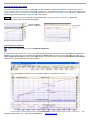
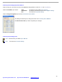
‘Dyna View V2’ Software User Manual
Advanced Dyno Data Viewing Software
www.dynapro.co.uk
Dyna Pro Dynamometers Ltd
United Kingdom
Tel UK: +44 (0) 8000 4321 68
Tel Int: +44 (0) 1256 363063
E-mail [email protected]
Table of Contents
INTRODUCTION
1
CONVENTIONS USED IN THIS M ANUAL
TECHNICAL SUPPORT
1
1
DYNA VIEW DISPLAY SUMMARY
2
DYNA VIEW SCREEN ICONS
2
DYNA VIEW CONTROLS
3
AIR CORRECTION FACTORS
DATA ‘SMOOTHING’
DJHP CORRECTION
DROP DOWN MENUS - ‘FILE’
DROP DOWN MENUS - ‘PROPERTIES’
DROP DOWN MENUS - ‘ENGINEERING UNITS’
DROP DOWN MENUS - ‘SPECIAL FUNCTIONS’
DROP DOWN MENUS - ‘HELP’
3
3
3
4
9
11
12
14
SCREEN FUNCTIONS
16
DATA LIST BOX
NOTES LIST BOX
CHANGING THE GRAPH AXIS LABELS
GRAPH BOX CONTROL BUTTONS
DISPLAY MULTIPLE GRAPH BOXES
COMMON LEFT & RIGHT GRAPH AXIS
AUTO SCALE GRAPH AXIS
GRAPH BOX SEPARATION
CHANGE THE GRAPH BOX SIZES
CURSOR READ-OUT DISPLAY
ZOOM IN / UNDO THE ZOOM
DATA PROPERTIES DIALOG
16
17
18
18
19
19
20
21
22
22
23
23
IMPORTANT NOTICE
25
ERROR MESSAGES
25
DYNA PRO END-USER LICENSE AGREEMENT
26
INDEX
28
Introduction
Welcome to the Dyna Pro Dynamometers Software manual for Dyna View V2. Please carefully read the installation
instructions for this software before commencing with the actual software install.
This software manual gives the user detailed information on program features, functions, menus and system
configurations, required for viewing ‘Dyno Run Files’.
Please be aware that this is a general software manual covering all aspects of the Dyna View V2 software, some of the
features, functions, menus and system configurations may not be available to the user as a result of those features being
specific to a particular model of Dynamometer.
Keep this reference manual in a convenient place, as it is a valuable reference source in the use of the Dyna View V2.
Conventions Used In This Manual
To make reading and understanding this manual more convenient certain naming conventions have been used
throughout this publication.
Convention Used
NOTES
CAUTION!!!
WARNING!!!
Description
The Note icon indicates a special point of notice for the operator.
The Caution icon indicates a potential hazard to the dynamometer equipment or to the vehicle
being tested. Follow all procedures exactly as they are described and use care when performing
all procedures.
The Warning icon indicates potential harm to the person performing a procedure and/or the
dynamometer equipment.
‘Italic’
Italic hyphened items are names, processes and menu names.
Bold
Bold Highlighted, items that you can select on within the software, including buttons, menus,
check boxes and radio buttons.
Technical Support
For technical support and assistance please contact Dyna Pro Dynamometers Ltd at +44 (0) 1256 363063 or an
appointed agent.
Dyna Pro Dynamometers Ltd can also be contacted by mail at Unit 18, Sherrington Way, Lister Road Industrial Estate,
Basingstoke, Hampshire. United Kingdom RG22 4DQ, or visit us on the world wide web at www.dynapro.co.uk, for the
latest product release and updates.
Dyna Pro Dynamometers Ltd
Dyna View V2 User Manual
www.dynapro.co.uk
1
Dyna View Display Summary
Data Controls
Drop Down Menus
Control Icons
Data List Box
Notes Box
Graph Identifier
Graph Identifier
Graph box 1
Right Hand Axis-Label
Graph box 1
Left Hand Axis-Label
Graph box 1
Correction Factors
Graph box 2
Graph Separation
Right Hand Axis-Label
Graph box 2
Left Hand Axis-Label
Graph box 2
Graph box 3
Right Hand Axis-Label
Graph box 3
Left Hand Axis-Label
Graph box 3
Bottom Axis-Label
Dyna View Screen Icons
Open Dyno Run from File.
Show three graphing boxes.
Selected Dyno Run Properties.
Graph box 3 - Common Left/Right axis.
axi
Clear all Dyno Runs from Graph.
Graph box 3 - Auto Scale both axis.
Exit Dyna View and returns to the ‘Make Run Screen’.
Quick Print.
Displays Run Data at the cursor position.
Show single graphing box.
Turn On/Off Multi-graph
graph Separations.
Graph box 1 - Common Left/Right axis.
Graph box 1 - Auto Scale both axis.
Open Graph identifier 1.
Show two graphing boxes.
Open Graph identifier 2.
Graph box 2 - Common Left/Right axis.
Open Graph identifier 3.
Graph box 2 - Auto Scale both axis.
Open Graph identifier 4.
If you place your ‘Mouse Cursor’ over any of the screen ‘Icons’ or ‘Dyna View controls’,, a windows help message box will
be displayed describing to you what this ‘Icon’ or ‘Control’ will do.
Dyna Pro Dynamometers Ltd
Dyna View V2 User Manual
www.dynapro.co.uk
2
Dyna View Controls
Air Correction Factors
Air Correction Factors can be selected from the drop-down menu box,
you can choose between five internationally accepted climate correction
factors.
These corrections adjust the power figures according to the current
climatic condition, i.e. Air Temperature, Air Pressure and Humidity. They
will compensate the power readings for engine performance from day to
day irrespective of the climatic conditions when the engine was tested.
It is strongly recommended that ‘None’ should not be used as this could
lead to inconsistent results as climatic changes occur during the day.
The correction settings for this function will always be displayed and printed in the bottom right of the primary graph.
None
SAE J1349
DIN 700200
ISO
EEC
ISA
No Air Correction Factor Standard
American Standard but used the world over
German Standards
International Organization for Standardization
European Standards
Standards for Automation
NOTES Air Correction Factors in most cases should only be applied to Normally Aspirated Engines, and not to
Turbo Charged or Super Charged engines. In these cases please select the ‘None’ option.
Data ‘Smoothing’
The data Smoothing control allows the displayed graph data to be mathematically averaged
between the ‘highs and lows’ to produce a smoother data output.
The Slider-Bar can be moved from ‘0’ No smoothing to ‘10’ for maximum smoothing.
No Data Smoothing (Slider-Bar set at ‘0’)
Full Data Smoothing (Slider-Bar set at ‘10’)
DJHP Correction
The DJHP Correction option box, when ticked, will display the Power and Torque data in
numbers that relate to other self proclaimed “Industry Standard” dynamometers. These
numbers are related to an estimation of ‘Engine Crank Power’.
Dyna Pro Dynamometers Ltd
Dyna View V2 User Manual
www.dynapro.co.uk
3
If DJHP Correction option box is NOT Ticked, the Power and Torque data displayed is the ‘True Rear Wheel’ power
being transferred to the dynamometer. ‘True Wheel Power’ will always read lower than crank estimated power.
The correction settings for this function will always be displayed and printed in the bottom right of the primary graph.
Drop Down Menus - ‘File’
Left Mouse Click on File to show the ‘file drop-down’ menu.
‘Open Graph’
Left Mouse Click on Open Graph to show the ‘Open File dialog window’.
Standard Open File Dialog Window
Select the file you wish to view then click on the Open button.
This dialog box is a standard Microsoft Windows dialog box; you
can change folders, create folders, rename files, and change
directories etc.
There is also two other ‘Open File Dialog Modes’, which are
activated by the Show Notes button and the Show Graph
button.
The Show Notes mode (Show Notes button pressed)
This dialog box is a standard Microsoft Windows dialog
box; you can change folders, create folders, rename files,
and change directories etc.
Dyna Pro Dynamometers Ltd
Dyna View V2 User Manual
www.dynapro.co.uk
4
By ‘Left Mouse Click’ on any of the ‘Dyno Run Files’,
Files’ the
File Run Properties window will update with the file
selected.
‘Double Left Mouse Click’ or pressing the ‘Open’ button will
then open the file in Dyna View.
The Show Graph mode (Show
Show Graph button
pressed)
This dialog box is a standard Microsoft Windows
dialog box; you can change folders, create folders,
rename files, and change directories etc.
‘Left mouse click’ on any of the ‘Dyno Run Files’,
Files’ the
‘File Run Properties’ window will update with the file
selected and a graph preview will be shown.
If you try to preview an invalid ‘Dyno Run File’ it will
display a message informing you that the file is not a
valid Dyno Run File.
‘Double left mouse click’ or pressing the Open button
will then open the file in ‘Dyna View’.
View’
This Icon has the same effect as File Open
Open.
Dyna Pro Dynamometers Ltd
Dyna View V2 User Manual
www.dynapro.co.uk
5
‘Recent Files’
The Recent Files option will show you a list of the last 15
‘Dyno Run files’ that have been
n opened and viewed.
You can ‘Left mouse click’ on any of these files and it will be
opened for viewing in ‘Dyna View’.
‘Run Data Properties’
Right mouse click on Run Data Properties to show the blue ‘Highlighted’ Dyno Run
properties window. Please see later for use of ‘Data Properties’ Dialog in the ‘Data List
Box’ chapter.
This Icon has the same effect as Run Data Properties.
‘Remove This Dyno Run’
Right mouse click on Remove this Dyno Run to delete the blue ‘Highlighted’ Dyno
Run from the Graph, this will also clear its data entries from the ‘Data List Box’.
Box’
Please see later for use of ‘Remove this Dyno Run’ function in the ‘Data List Box’
chapter.
‘Remove All Runs’
Select this option to clear all currently opened Dyno Run File data from the Graphs.
This will also clear all of the data entries from the ‘Data List Box’.
This Icon has the same effect.
Dyna Pro Dynamometers Ltd
Dyna View V2 User Manual
www.dynapro.co.uk
6
‘Print Set-up’
Select this function to set-up your printer defaults, Paper size, Orientation, Quality etc.
The ‘Printer’ dialog box options will vary depending on what printer you have installed.
This option must be selected before you can use the Quick Print button Icon.
‘Print Options’
Select this function to open the ‘Printing Options’ menu shown below. From this menu
you can select or deselect items that will be shown on the printed graph.
This option is also available from within the ‘Print Preview’ screen.
Select or Deselect the required Check Boxes for the print options that you
require.
When you have finished click on the Save & Exit button.
‘Print Preview’
Select this function to show printing preview of what you are about to ‘Print’.
Dyna Pro Dynamometers Ltd
Dyna View V2 User Manual
www.dynapro.co.uk
7
The Print Preview will display a representation of what
you are about to print, if you want to change any print
setting then go to the File drop-down
down menu and select
Print Set-up.
Select the Print option to print the displayed document.
Select Exit to leave ‘Print Preview’ without printing.
You can also ‘Zoom’ in on the displayed graph by
holding the Left Mouse button and ‘dragging’ a window
over the area that you wish to enlarge,
enla
release the
mouse button when done. You can also use the bottom
and side ‘scroll bars’ to adjust the zoomed position.
If you wish to ‘Un-Zoom’ then right mouse click and
Select Undo Zoom from the cursor drop-down
drop
menu.
‘Print’
This will print the document according to how you have set
set-up
up the ‘Print Set-up’ & ‘Print
Options’ menus.
This Icon has the same effect.
‘Exit’
This function will end your session with ‘Dyna View’, if you are using ‘Dyna View’ as
just a viewer package then you will be returned to your windows desktop, but if you are
using ‘Dyna View’ from within ‘Dyna Run’ you will be returned to the ‘Make Run
Screen’.
This Icon has the same effect.
Dyna Pro Dynamometers Ltd
Dyna View V2 User Manual
www.dynapro.co.uk
8
Drop Down Menus - ‘Properties’
Left mouse click on Properties to show the properties drop-down menu.
‘Shown Notes Info’
If this function has a ‘tick’ to the left of it, then the ‘Notes’ list box will be shown, else the ‘Notes’ list box will be invisible.
Dyna View with Notes List Box
Dyna View without Notes List Box
‘Show Maximize’
If this function is selected [a ‘tick’ to the left of it] the displayed graph will be maximized over the full screen, it will not
show the ‘Data List Box’ or the ‘Notes Box’.
Display Maximized
‘Multi Gear Auto Select’
If Multi Gear Auto Select has a tick to the left of it, then the system will read the ‘Dyno Run’ data and then determine if it
was a ‘Multi Gear’ run or a ‘Single Gear’ run, if it determines that the ‘Dyno Run’ was a ‘Multi Gear’ run then it will
automatically change the ‘Bottom-Axis’ label of the graph to either ‘Road Speed’, ‘Time’ or ‘Distance’ depending on what
you have selected in Auto Detect Display options.
Dyna Pro Dynamometers Ltd
Dyna View V2 User Manual
www.dynapro.co.uk
9
‘Auto Detect Display’
Select the ‘Bottom-Axis’ label you require, when a ‘Multi Gear Run’ has been
detected.
You can select between ‘Road Speed’, ‘Time’ or ‘Distance’.
‘Save As Manual Open Default’
If you select this function you will be prompted by: -
If you click Yes, then all graph settings, Axis-Labels, correction
factors, scales etc, will be saved as the graph default values.
Any time that you open a ‘Dyno Run’ for viewing it will always open
with your default graph settings.
Dyna Pro Dynamometers Ltd
Dyna View V2 User Manual
www.dynapro.co.uk
10
Drop Down Menus - ‘Engineering Units’
Left mouse click on Engineering Units Set-up to show the ‘Engineering Units
Set-up’ drop-down menu.
The ‘In brackets’ part tells you what units have been selected, i.e. Metric, SAE, Japanese, or Custom settings.
‘Engineering Units Set-up’
You may wish to choose a ‘Standard Unit’ set-up, Metric, SAE
or Japanese. If this is the case then just left mouse click one of
the options and then all the Unit Fields will be updated.
If you prefer to work in the Units that suit you then, from each of
the headings pull down the drop-down menu and select the
Units you require.
The Options at the top will now automatically select ‘Custom’.
When you have finished click on the Save & Exit button.
Dyna Pro Dynamometers Ltd
Dyna View V2 User Manual
www.dynapro.co.uk
11
Drop Down Menus - ‘Special Functions’
Left mouse click on Special Functions to show the ‘Special
Functions’ drop-down menu.
Special Functions include calculating the ‘Area Under Graph’,
‘upper and lower Air Fuel line annotations’, ‘Atmospheric Condition
Warnings, and a ‘Calculator’.
‘Area Under Graph Properties’
The Area Under Graph Properties dialog box allows the user to set a ‘lower ‘X’
axis’ point, an ‘upper ‘X’ axis’ point and a ‘base line point’.
The Area Under the Graph will be calculated between these three points.
NOTES Area Under the Graph will only be calculated if Power and Torque are
plotted against Engine Speed.
Area Under Graph is calculated in this area only.
The results will be shown in the ‘Notes Box’.
If Show Area Line Annotations has a tick to the left
of it, then ‘Dyna View’ will show the calculation limits on
the graph.
Area Under Graph Data
Area Under Graph is calculated in this area only.
Dyna Pro Dynamometers Ltd
Dyna View V2 User Manual
www.dynapro.co.uk
12
‘Air/Fuel Limits Properties’
The Air/Fuel Limits Properties dialog box allows the user to set an ‘upper and
lower Air/Fuel Annotation Line’ to the graph.
If Show Air/Fuel Annotations
has a tick to the left of it, ‘Dyna
View’ will show the ‘Upper and
Lower Air/Fuel annotation Lines’.
Upper and Lower Air/Fuel Annotation lines.
‘Atmospheric Condition Warning’
The Atmospheric Condition Warnings dialog box allows the user to set
‘atmospheric parameters’, which will then warn the user if these limits
have been exceeded when opening and displaying Dyno Runs.
Each of the 5 parameters can be enabled/disabled, and there warning
limits changed.
If the ‘Always show the above Atmospheric differences when opening
Dyno Runs’ is selected, then every time that you Open a ‘Dyno Run’ its
atmospheric differences will be shown regardless of what limit
parameters were set.
When you have finished click on the Save & Exit button.
‘Calculator’
This function will display the Microsoft™ system
calculator.
Dyna Pro Dynamometers Ltd
Dyna View V2 User Manual
www.dynapro.co.uk
13
Drop Down Menus - ‘Help’
Left mouse click on Help to show the ‘Help’ drop-down menu.
‘Dyna View Manual’
Left mouse click on Dyna View Manual to show this manual.
NOTES That ‘Adobe Reader’ must be installed on the user’s computer
to be able to view this file.
‘Key Strokes / Function Keys’
Left mouse click on Key Stroke / Function Keys to open a PDF File that
allows you to print out the Key Legend Strips, for placing above the function
keys on your keyboard.
NOTES That ‘Adobe Reader’ must be installed on the user’s computer
to be able to view this file.
Key Legend Strips for 4x3 and 3x4 function key arrangements.
Key strokes are a convenient way to navigate around the software without the need for using the mouse. The ‘Dyna Run’
and ‘Dyna View’ software both accept the use of key strokes for all common tasks.
Dialog windows, Message Boxes, Menu’s, etc have also got further controls;
‘Tab’ Key
‘Return’ Key
‘Escape’ Key
Pressing the ‘Tab’ Key will move the Data Cursor position to the next logical input box.
Pressing the ‘Return’ Key will has the same effect as press the OK button, Save and Exit Button.
Pressing the ‘Escape’ Key within any dialog window will close the window without saving any data that
you have entered.
Dyna Pro Dynamometers Ltd
Dyna View V2 User Manual
www.dynapro.co.uk
14
Dyna View Key Stroke Function List
F1
F2
F3
F4
F5
F6
F7
F8
F9
F11
F12
Help
Open Graph
Clear All Graph Data
Remove Selected Graph Data
Selected Graph Properties
Area Properties Menu
Area Annotations (Enable / Disable)
Air Fuel Display Menu
Air Fuel Annotations (Enable / Disable)
Climate Warning Menu
Exit
‘Product Brochure’
Left mouse click on Product Brochure to show Dyna Pro products, parts
and news.
NOTES That ‘Adobe Reader’ must be installed on the user’s computer
to be able to view this file.
‘About’
Left mouse click on About, to show the ‘Software and Hardware Version
Information’.
Dyna Pro Dynamometers Ltd
Dyna View V2 User Manual
www.dynapro.co.uk
15
Screen Functions
Data List Box
The ‘Data List Box’ shows information from each of the displayed ‘Dyno Runs’, please note that a maximum of 4 Dyno
Runs can be shown at any one time.
The ‘Data List Box’ shows you a ‘Graph Identifier’, Dyno Run name, time and date that when it was done, file location and
its peak power and torque.
The ‘Data List Box’ can do much more though, if you Left Mouse Click on one of the ‘Dyno Runs’ listed, it will ‘Highlight’
that ‘Dyno Run’ on the graphs and ‘Highlight’ the data in blue, in the ‘Data List Box’: -
Double left mouse click in the
‘Graph Area’ to undo the
‘Highlighting’.
You can also right mouse click on the ‘Dyno Run’ in the ‘Data List
Box’ and this will show a ‘Cursor drop-down Menu’: Left mouse click on Remove This Dyno Run to delete the blue
‘Highlighted’ Dyno Run from the Graph, this will also clear its data
entries from the ‘Data List Box’.
Left mouse click on Remove all Dyno Runs to delete and clear all
Dyno Runs from the graphs, this will also clear all data entries from
the ‘Data List Box’.
This Icon has the same effect as above.
Left mouse click on Run Data Properties to show the blue ‘Highlighted’ Dyno Run properties window. Please see later
for use of ‘Data Properties’ Dialog.
Dyna Pro Dynamometers Ltd
Dyna View V2 User Manual
www.dynapro.co.uk
16
Once a Dyno Run has been ‘Highlighted’ in blue, in the ‘Data List Box’,, this Icon has the same effect as above.
Make this Dyno Run system Reference this function only works for ‘Dyna Run’, please refer to ‘Dyna Run Manual’ for
more details on this function.
Left mouse click on Delete File From Computer (WARNING) to permanently delete the blue ‘Highlighted’ Dyno Run
from the Graph and from your ‘Hard Drive’,, this will also clear its data entries from the ‘Data List Box’.
Box’ The message box
shown below will be displayed to confirm that you want to permanently delete this file
file.
Use this function
nction with care, as once deleted it is gone forever.
Notes List Box
The ‘Notes List Box’ gives you extra data about the ‘Dyno Run’ that has been ‘highlighted’ in blue from the ‘Data List Box’.
This data includes any ‘notes’ that you or the dyno operator entered before or after commencing with the ‘Dyno Run’ and
also includes: Dyno Run Name
The Air Temperature from when the engine was run on the dyno.
The Air Pressure from when the engine was run on the dyno.
The
he Humidity from when the engine was run on the dyno.
C/F – Air correction factor [this is dependent on what air correction factor was selected]
RAD – Relative Air Density
Area Under Graph for Power
Area Under Graph for Torque
Front & Rear Sprocket sizes
[EBK Range Dyno’s only]
Rear Wheel Diameter
[EBK Range Dyno’s only]
Dyna Pro Dynamometers Ltd
Dyna View V2 User Manual
www.dynapro.co.uk
17
Changing the Graph Axis Labels
You can change all the ‘Graph Axis
Labels’ to any standard ‘Data
Channel’, or if any addition sensors
were install on the system they will
also be made available. For Example,
TPS, Thermocouple Sensors,
Pressure.
If you put your mouse cursor over any
of the ‘Graph Axis Labels’ you will
notice that it changes from an ‘Arrow
Pointer’ to a ‘Hand pointer’.
When this occurs you can then left
mouse click and this will display a
‘Pop Up Menu’ with a list of all
available ‘Data Channels’.
Move the mouse cursor up or down
the list, then left mouse click on the
‘Data Channel’ that you wish to
display.
All ‘Graph Axis Labels’ can be
changed to any available ‘Data Channel’. This includes Left Hand, Right Hand and Bottom ‘Axis Labels’. See Below: -
Graph Box Control Buttons
The ‘Graph Box Control Buttons’ are arranged as 3 groups of 3 buttons, the first group of 3 all relate to ‘Graph Box 1’, the
second group of 3 all relate to ‘Graph Box 2’ and the third group of 3 all relate to ‘Graph Box 3’.
These buttons allow the user to control how many ‘Graph Boxes’ are displayed, there scaling functions, and there ‘Axis
Locking’ functions.
Graph Box Control Buttons
Graph Box 1
Controls
Dyna Pro Dynamometers Ltd
Dyna View V2 User Manual
Graph Box 2
Controls
www.dynapro.co.uk
Graph Box 3
Controls
18
Display Multiple Graph Boxes
You can display up to three ‘Graph Boxes’ with Dyna View. You can change the Left and Right ‘Graph Axis Labels’ on
each displayed ‘Graph Box’. The Bottom ‘Graph Axis Label’ is relative to all the ‘Graph Boxes’ displayed.
splayed.
You can add these additional ‘Graph Boxes’ by left mouse click on the appropriate Icon buttons as follows: -
Show single graphing box.
Show two graphing boxes.
Show three graphing boxes.
Double Graph Box
Single Graph Box
Triple Graph Box
Common Left & Right Graph Axis
If one of the ‘Common Left/Right Axis’ buttons is selected, shown below, this will lock the ‘Left and Right Axis’ to be the
same on both sides of the ‘Graph Box’.. You can control the ‘Common Left/Right Axis’ on each individual ‘Graph Box’.
‘Graph Box 1’ – Common Left/Right Axis
‘Graph Box 2’ – Common Left/Right Axis
‘Graph Box 3’ – Common Left/Right Axis
Notice that the ‘Left and Right Axis’s’ are both
scaled the same [0 to 130].
This ‘Icon’ appears to be pressed.
Dyna Pro Dynamometers Ltd
Dyna View V2 User Manual
www.dynapro.co.uk
19
Notice that the ‘Left and Right Axis’s’ are NOT
scaled the same. The left hand side is scaled 0 to
130, and the right hand side is scaled 0 to 65.
This ‘Icon’ Appears to be raised.
Auto Scale Graph Axis
If one of the ‘Auto Scale Axis’ buttons is selected, shown below, this will ‘Auto Scale’ the ‘Graph Box’ data. You can
control the ‘Auto Scale Axis’ on each individual ‘Graph Box’
Box’.
‘Graph Box 1’ – Auto Scale Axis
‘Graph Box 2’ – Auto Scale Axis
‘Graph Box 3’ – Auto Scale Axis
Notice that the ‘Left and Right Axis’s’ are now both
scaled from [0 to 130].
This ‘Icon’ appears to be pressed.
Dyna Pro Dynamometers Ltd
Dyna View V2 User Manual
www.dynapro.co.uk
20
Notice that the ‘Left and Right Axis’s’ are now both
scaled from [40 to 130].
This ‘Icon’ Appears to be raised.
Graph Box Separation
Turn On/Off ‘Multi-graph Separations’ by left mouse clicking.
Axis Separation
With Axis Separation
Dyna Pro Dynamometers Ltd
Dyna View V2 User Manual
No Axis Separation
www.dynapro.co.uk
21
Change the Graph Box Sizes
If you have more than one ‘Graph Box’ displayed, it is also possible to change their size/ratio. If you move the
t ‘Mouse
Cursor’ over the ‘Bottom Axis’ of one of the upper ‘Graph Boxes’, you will notice that the ‘Cursor Arrow’ will change from a
‘Single Arrow Pointer’ to a ‘Double Arrow Pointer’
Pointer’. When this occurs you can ‘Click and Hold the Left Mouse’ button down
whilst dragging the bottom of the ‘Graph Box’ to its new position.
NOTES All ‘Graph Boxes’ have a minimum size set as default; if you try to make a ‘Graph Box’ to small it will
automatically resize itself to its smallest default size.
Drag this
is section
of the ‘Graph Box’
Resized Bottom
‘Graph Box’
Cursor Read-out Display
This ‘Icon’ if selected will turn on the Cursor Data Read
Read-out.
If you left mouse click over a ‘Dyno Run graph’ it will display data at the point at which the mouse button was pressed. In
addition to the mouse click you can also use the Keyboard Arrow Keys to move the cursor data along the graph. The
Left and Right, Arrow Keys move the cursor data along by one step at a time, whereas the Up and Down, Arrow Keys
will move the cursor data along by 10 steps at a time.
Dyna Pro Dynamometers Ltd
Dyna View V2 User Manual
www.dynapro.co.uk
22
‘Data Cursor Read Out’
Zoom In / Undo the Zoom
Zooming is the process of using the mouse to select new extents of the graphs grid. Any individual ‘Graph Box’ can be
zoomed in on, and then zoomed in on again. Zooming can also be done over multiple ‘Graph Boxes’ if required.
To Zoom:
1. Press the Left Mouse Button and hold down whilst ‘dragging’ the cursor to select the new extents.
2. Release the Mouse Button.
To Undo the Zoom:
Press the ‘Z’ key or use the popup menu, Right Mouse Click to select the ‘Undo Zoom’ menu item.
When you have ‘Zoomed’ in on a graph you can use the bottom and side Scroll Bars to adjust the position of the zoom.
Data Properties Dialog
If you have selected to open a ‘Graph Properties’ dialog window, see above for how to do this, you can now view
additional ‘Dyno Run’ information, and even add delete or modify certain parts of the data.
If you change any of the data fields you will need to save the changes before leaving the ‘Data Properties Dialog’.
‘Data Fields’ that are coloured ‘Light
Blue’ can all be modified or edited.
All other data fields are for reference
and cannot be changed by the user.
NOTES If you have opened any Dyno
Runs which have been opened from
‘Read Only’ data media, i.e. CD, DVD,
though you can modify the ‘Graph
Properties Dialog’ data you will not be
able to Save this data back to the data
media that is was ‘Read’ from.
To Save the edited data fields, either
left mouse click on the Save Icon, or
drop-down the file menu and select
Save or Save & Exit.
When you select Save a warning
message will be displayed showing
‘Are you sure you want to save this
edited Dyno Run File’, Select Yes to
‘Save’.
Dyna Pro Dynamometers Ltd
Dyna View V2 User Manual
www.dynapro.co.uk
23
‘Data Properties Dialog Drop Down Menus’
There are only two ‘drop down’ menus in the properties dialog window. These are ‘File’ and ‘Engineering’.
‘Engineering’
Under the File Menu you will see
Save
Save & Exit
Exit
-This will save your edited ‘Dyno Run file’.
-This will save and then exit from the ‘Properties Dialog’.
Dialog’
-This exits the ‘Properties Dialog’.
Under the Engineering Menu you will see ‘Aux Channel Name Editor
Editor’.
This dialog box allows you tto change the name of the ‘Auxiliary Data Channels’.
Channels’
Click Save & Exit when you have completed your changes.
‘Data Properties Dialog Icons’
‘Save’ -This will save your edited ‘Dyno Run file’
file’.
‘Exit’
-This exits the ‘Properties Dialog’.
Dyna Pro Dynamometers Ltd
Dyna View V2 User Manual
www.dynapro.co.uk
24
Important Notice
Please be aware that some ‘Functions’ and ‘Menu Options’ described above may or may not be available on the ‘Dyno
Run File’ that has been opened. Some ‘Functions’ and ‘Menu Options’ are dependent on the Dynamometer Model and
Accessories used to produce the ‘Dyno Run File’.
Error Messages
If when opening a ‘Dyno Run File’ you get a message box displayed showing an error message ‘GOR-3’, this is caused
normally by an invalid or corrupted ‘Dyno Run File’.
Dyna Pro Dynamometers Ltd
Dyna View V2 User Manual
www.dynapro.co.uk
25
Dyna Pro End-User License Agreement
YOU SHOULD CAREFULLY READ THE FOLLOWING TERMS AND CONDITIONS BEFORE USING THIS PRODUCT.
IT CONTAINS SOFTWARE, THE USE OF WHICH IS LICENSED BY DYNA PRO DYNAMOMETERS LTD., TO ITS
CUSTOMERS FOR THEIR USE ONLY AS SET FORTH BELOW. IF YOU DO NOT AGREE TO THE TERMS AND
CONDITIONS OF THIS AGREEMENT, DO NOT USE THE SOFTWARE. USING ANY PART OF THE SOFTWARE
INDICATES THAT YOU ACCEPT THESE TERMS.
GRANT OF LICENSE: Dyna Pro Dynamometers Ltd. (the "Licensor") grants to you this personal, limited, non-exclusive,
non-transferable, non-assignable license solely to use in a single copy of the Licensed Works on a single computer for
use by a single concurrent user only, and solely provided that you adhere to all of the terms and conditions of this
Agreement. The foregoing is an express limited use license and not an assignment, sale, or other transfer of the
Licensed Works or any Intellectual Property Rights of Licensor.
ASSENT: By opening the file package containing this software, you agree that this Agreement is a legally binding and
valid contract, agree to abide by the intellectual property laws and all of the terms and conditions of this Agreement, and
further agree to take all necessary steps to ensure that the terms and conditions of this Agreement are not violated by any
person or entity under your control or in your service.
OWNERSHIP OF SOFTWARE: The Licensor and/or its affiliates or subsidiaries own certain rights that may exist from
time to time in this or any other jurisdiction, whether foreign or domestic, under patent law, copyright law, publicity rights
law, moral rights law, trade secret law, trademark law, unfair competition law or other similar protections, regardless of
whether or not such rights or protections are registered or perfected (the "Intellectual Property Rights"), in the computer
software and hardware, together with any related documentation (including design, systems and user) and other
materials for use in connection with such computer software in this package (collectively, the "Licensed Works"). ALL
INTELLECTUAL PROPERTY RIGHTS IN AND TO THE LICENSED WORKS ARE AND SHALL REMAIN IN
LICENSOR.
PRODUCT ACTIVATION: Your use of the Software is governed by product activation technology that limits the number
of installations and total number of computers on which the Software. This product activation technology may not be
circumvented or otherwise disabled in any way.
RESTRICTIONS:
(a) You are expressly prohibited from copying, modifying, merging, selling, leasing, redistributing, assigning, or
transferring in any matter, Licensed Works or any portion thereof.
(b) You may take a single copy of materials within the package or otherwise related to Licensed Works only as required
for backup purposes.
(c) You are also expressly prohibited from reverse engineering, decompiling, translating, disassembling, deciphering,
decrypting, or otherwise attempting to discover the source code of the Licensed Works as the Licensed Works contain
proprietary material of Licensor. You may not otherwise modify, alter, adapt, port, or merge the Licensed Works.
(d) You may not remove, alter, deface, overprint or otherwise obscure Licensor patent, trademark, service mark or
copyright notices.
(e) You agree that the Licensed Works will not be shipped, transferred or exported into any other country, or used in any
manner prohibited by any government agency or any export laws, restrictions or regulations.
(f) You may not publish or distribute in any form of electronic or printed communication the materials within or otherwise
related to Licensed Works, including but not limited to the object code, documentation, help files, examples, and
benchmarks.
TERM: This Agreement is effective until terminated. You may terminate this Agreement at any time by uninstalling the
Licensed Works and destroying all copies of the Licensed Works. Upon any termination, you agree to uninstall the
26
Dyna Pro Dynamometers Ltd
Dyna View V2 User Manual
www.dynapro.co.uk
Licensed Works and return or destroy all copies of the Licensed Works, any accompanying documentation, and all other
associated materials.
GOVERNING LAW: This License Agreement shall be governed by the laws of the United Kingdom.
WARRANTIES AND DISCLAIMER:
EXCEPT AS EXPRESSLY PROVIDED OTHERWISE IN A WRITTEN AGREEMENT BETWEEN LICENSOR AND YOU,
THE LICENSED WORKS ARE NOW PROVIDED ÒAS ISÓ WITHOUT WARRANTY OF ANY KIND, EITHER EXPRESS
OR IMPLIED, INCLUDING, BUT NOT LIMITED TO, THE IMPLIED WARRANTIES OF MERCHANTABILITY OR
FITNESS FOR A PARTICULAR PURPOSE, OR THE WARRANTY OF NON-INFRINGEMENT. WITHOUT LIMITING
THE FOREGOING, LICENSOR MAKES NO WARRANTY THAT (i) THE LICENSED WORKS WILL MEET YOUR
REQUIREMENTS, (ii) THE USE OF THE LICENSED WORKS WILL BE UNINTERRUPTED, TIMELY, SECURE, OR
ERROR-FREE, (iii) THE RESULTS THAT MAY BE OBTAINED FROM THE USE OF THE LICENSED WORKS WILL
BE ACCURATE OR RELIABLE, (iv) THE QUALITY OF THE LICENSED WORKS WILL MEET YOUR
EXPECTATIONS, (v) ANY ERRORS IN THE LICENSED WORKS WILL BE CORRECTED, AND/OR (vi) YOU MAY
USE, PRACTICE, EXECUTE, OR ACCESS THE LICENSED WORKS WITHOUT VIOLATING THE INTELLECTUAL
PROPERTY RIGHTS OF OTHERS.
SEVERABILITY: In the event any provision of this License Agreement is found to be invalid, illegal or unenforceable, the
validity, legality and enforceability of any of the remaining provisions shall not in any way be affected or impaired and a
valid, legal and enforceable provision of similar intent and economic impact shall be substituted therefore.
ENTIRE AGREEMENT: This License Agreement sets forth the entire understanding and agreement between you and
Dyna Pro Dynamometers Ltd., supersedes all prior agreements, whether written or oral, with respect to the Software, and
may be amended only in a writing signed by both parties.
Dyna Pro Dynamometers Ltd
Unit 18, Sherrington Way
Lister Road Industrial Estate
Basingstoke,
Hampshire
United Kingdom
RG22 4DQ
Dyna Pro Dynamometers Ltd
Dyna View V2 User Manual
www.dynapro.co.uk
27
Index
A
I
About ...................................................................... 14, 15
Air Correction Factors .................................................... 3
Air/Fuel Limits Properties............................................. 13
Area Under Graph Properties....................................... 12
Atmospheric Condition Warning .................................. 13
Auto Detect Display ...................................................... 10
Auto Scale Graph Axis .................................................. 20
Aux Channel Name Editor ............................................ 24
Icons ............................................................................... 2
Important Notice ...................................................... 25, 1
Introduction ................................................................... 1
ISA................................................................................... 3
ISO .................................................................................. 3
C
M
Calculator ..................................................................... 13
Change the Graph Box Sizes ......................................... 22
Changing the Graph Axis Labels ................................... 18
Common Left & Right Graph Axis ................................. 19
Conventions Used .......................................................... 1
Cursor Read-out Display ............................................... 22
Multi Gear Auto Select ................................................... 9
Multi-graph Separation ................................................ 21
D
Open Graph .................................................................... 4
Data List Box ................................................................. 16
Data Properties Dialog ................................................. 23
Data Properties Dialog Drop Down Menus .................. 24
Data Properties Dialog Icons ........................................ 24
Delete File From Computer .......................................... 17
DIN 700200 ..................................................................... 3
Display Multiple Graph Boxes ...................................... 19
DJHP Correction ............................................................. 3
Drop Down Menus ......................................................... 4
Drop Down Menus - ‘Engineering Units’ ...................... 11
Drop Down Menus - ‘Help’ ........................................... 14
Drop Down Menus - ‘Properties .................................... 9
Drop Down Menus - ‘Special Functions’ ...................... 12
Dyna Pro Dynamometers Ltd ......................................... 1
Dyna View Controls ........................................................ 3
Dyna View Display Summary .......................................... 2
Dyna View Key Stroke Function List ............................. 15
P
E
EEC .................................................................................. 3
End-User License Agreement ....................................... 26
Engineering Units Set-up .............................................. 11
Error Messages ............................................................. 25
Escape Key .................................................................... 14
Exit .................................................................................. 8
F
Function Keys ......................................................... 14, 15
G
K
Key Strokes ................................................................... 14
N
Notes List Box ............................................................... 17
O
Print ................................................................................ 8
Print Options .................................................................. 7
Print Preview .................................................................. 7
Print Set-up .................................................................... 7
R
Recent Files .................................................................... 6
Remove All Runs....................................................... 6, 16
Remove This Dyno Run ............................................ 6, 16
Return Key .................................................................... 14
Run Data Properties ................................................. 6, 16
S
SAE J1349 ....................................................................... 3
Save As Manual Open Default ...................................... 10
Screen Functions .......................................................... 16
Show Maximize .............................................................. 9
Shown Notes Info ........................................................... 9
Smoothing ...................................................................... 3
T
Tab Key ......................................................................... 14
Table Of Contents........................................................... 3
Technical Support........................................................... 1
Z
Zoom In / Undo the Zoom ............................................ 23
Graph Box Control Buttons .......................................... 18
Graph Box Separation .................................................. 21
Dyna Pro Dynamometers Ltd
Dyna View V2 User Manual
www.dynapro.co.uk
28
st
Compiled Date 1 January 2011
Dyna Pro Dynamometers Ltd reserves the right to change specifications without notice.
© 2011 Dyna Pro Dynamometers Ltd. All rights reserved.
www.dynapro.co.uk
Dyna Pro Dynamometers Ltd
United Kingdom
Tel UK: +44 (0) 8000 4321 68
Tel Int: +44 (0) 1256 363063
E-mail [email protected]