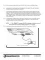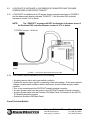
1
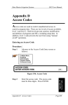
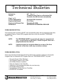
Technical Bulletin
Bulletin No.
Subject:
037 Rev. A
Troubleshooting Tips for an Evolution DX2
Controller that will not start automatically
Page 1 of 11
Product Applicability:
Engineering Release:
Engineering Release Date:
Distribution:
Evolution DX2 Controllers
R. A. Olson
December 02, 2004
APPROVED FOR GENERAL RELEASE
PROBLEM DESCRIPTION:
The Evolution DX2 Controller will NOT start automatically either with a programmed start time,
an Individual Station Control (ISC) program start time or with the controller “PROGRAM
ON/OFF” key.
NOTE:
The PROGRAM ON/OFF key operates the same as a programmed
start, except that the key will start a "Partial Program" where as a
programmed start time will not.
NOTE:
A partial program is a program without one or two of the three
elements; a start time, water days or station runtimes.
PROBLEM RESOLUTION:
There are 8 situations listed below that will not allow the controller to perform an Automatic
Program Start, an Automatic ISC Program Start or a "PROGRAM ON/OFF" key start.
• The controller is in Rain Shutdown
• The Program Percent is set to Zero
• A No Water Window is enabled
• There are Alarms in the Controller
• Continuous Cycle programming with only one time entry
• A Flow Max setting in error
• A standalone controller that is in Flow Max
• A DXCID-KIT is installed
Technical Bulletin 037
Sheet 1 of 11
3910-B Royal Avenue
Simi Valley, CA 93063
Tel: (805) 527-4498
Fax: (805) 527-2813
1.0
SITUATION ONE: THE CONTROLLER IS IN RAIN SHUTDOWN
Reference: Evolution DX2 User’s Manual and Field Maintenance Guide, page 8-15.
The Evolution DX2 controller may be placed into Rain Shutdown to stop watering for
either an indefinite amount of time or a User specified period (1 – 7 days).
When the controller is placed into Rain Shutdown, the Base Screen displays “RAIN
SHUTDOWN” in place of the valid programs list. The controller will remain in Rain
Shutdown indefinitely. The User is responsible for taking the controller out of Rain
Shutdown.
When the controller is placed into Programmable Rain Shutdown and the rain days have
been entered, the Base Screen shows “RAIN SHUTDOWN DAYS LEFT = X”, where “X”
is the number of programmed days entered (1 – 7). This number automatically
decrements at 12:00 AM each day. The controller will automatically come out of Rain
Shutdown at the end of the User specified period.
1.1
NOTE:
The controller WILL NOT allow an automatic program start or an
automatic ISC program start to take place.
NOTE:
The controller WILL allow a manual program start via the “PROGRAM
ON/OFF” key. Also, the controller WILL allow individual stations to be
turned on manually.
To start watering programs again, Rain Shutdown must be turned off. The controller
menu path is;
QUIT = Returns the controller to the Base Screen
F1 = Main Menu
F4 = Manual & Rain Off
F4 = Rain Off
F1 = Rain Shutdown
F2 = Off (Automatic Mode)
1.2
Press the QUIT key to return to the Base Screen.
Technical Bulletin 037
Sheet 2 of 11
3910-B Royal Avenue
Simi Valley, CA 93063
Tel: (805) 527-4498
Fax: (805) 527-2813
2.0
SITUATION TWO: THE PROGRAM PERCENT IS SET TO ZERO
Reference: Evolution DX2 User’s Manual and Field Maintenance Guide, page 5-19.
The Program Percent feature provides the ability to alter the run times of all stations in a
given program. Reducing the percentage factor will shorten all run times while increasing
the percentage factor will increase all runtimes accordingly. With the Program Percent
set to zero, even though the program shows time on the stations, water days and start
times, there is no actual run time.
2.1
To verify and/or change the Program Percentage setting, the controller menu path is;
QUIT = Returns the controller to the Base Screen
F1 = Main Menu
F1 = Program
F1 = Modify Program (enter the program number)
F4 = Percent
2.2
The PERCENTAGE OF STATION RUNTIME value will be displayed. Set this value to
the desired percentage (typically 100%) and then press Enter.
2.3
Press the QUIT key to return to the Base Screen.
Technical Bulletin 037
Sheet 3 of 11
3910-B Royal Avenue
Simi Valley, CA 93063
Tel: (805) 527-4498
Fax: (805) 527-2813
3.0
SITUATION THREE: A NO WATER WINDOW IS ENABLED
Reference: Evolution DX2 User’s Manual and Field Maintenance Guide, page 8-15.
The No Water Window feature selects a period of time during the day when watering is
disallowed, up to 23 hours and 59 minutes per day. Any scheduled start times which
occur during the No Water Window period will be ignored. Attempting to start a program
with the PROGRAM ON/OFF key shall have no effect. If a program is running and the
No Water Window time is reached, the controller will stop its irrigation.
NOTE:
3.1
This is a universal controller setting; ALL programs will be prohibited
from running.
To verify and/or change the No Water Window setting, the controller menu path is;
QUIT = Returns the controller to the Base Screen
F1 = Main Menu
F4 = Manual & Rain Off
F4 = Rain Off
F2 = No Water Window
3.2
The START TIME FOR WATER WINDOW is displayed. To clear this value press Zero,
Zero, Zero, Zero, Enter.
3.3
The END TIME FOR WATER WINDOW is displayed. To clear this value press Zero,
Zero, Zero, Zero, Enter.
3.4
Press the QUIT key to return to the Base Screen.
Technical Bulletin 037
Sheet 4 of 11
3910-B Royal Avenue
Simi Valley, CA 93063
Tel: (805) 527-4498
Fax: (805) 527-2813
4.0
SITUATION FOUR: THERE ARE ALARMS IN THE CONTROLLER
Reference: Evolution DX2 User’s Manual and Field Maintenance Guide, page 10-2.
If there is an alarm/warning in the controller that shuts off the controller and it is not
cleared, the controller will not operate automatically.
Examples would be;
• A high flow on the main line
• A high or low flow on all stations in a program
• A high or low current on the master valve
4.1
If an alarm condition has been detected, the second line of the Base Screen will show;
(The current date), (The current week), F1 = Main Menu, F2 = WARNING.
4.2
After the problem has been resolved, clear all warnings at the controller. The controller
menu path is;
QUIT = Returns the controller to the Base Screen
F2 = Warning
= Press the down arrow key to advance through the warning list
F1 = Clear Report Messages
(Press F1 to clear the warnings and return to the Base Screen)
Technical Bulletin 037
Sheet 5 of 11
3910-B Royal Avenue
Simi Valley, CA 93063
Tel: (805) 527-4498
Fax: (805) 527-2813
5.0
SITUATION FIVE: CONTINUOUS CYCLE PROGRAMMING WITH ONLY ONE TIME
ENTRY
Reference: Evolution DX2 User’s Manual and Field Maintenance Guide, page 4-8.
When a continuous cycle is selected in the program set up area, it is necessary to give at
least two time entries, one for the start of the cycle and one for the end of the cycle. A
third entry can be given for a delay between cycles, if desired. If no third time is entered,
the cycles will immediately repeat until the end time is reached.
5.1
NOTE:
A Rain Master Controller will never start a station without a
predetermined end time. In Continuous Cycle mode, if only one time
entry is entered the program will NOT start automatically with a
programmed start, but it WILL start with the Program On/Off Key.
NOTE:
This setting is on a per program basis, other programs will be allowed
to run.
To verify and/or change the Cycle Mode setting, the controller menu path is;
QUIT = Returns the controller to the Base Screen
F1 = Main Menu
F5 = Setup
F1 = Program (enter the program number)
5.2
The CYCLE MODE setting will now be displayed. The setting options are Start Times
and Continuous Cycle. Press the F1 key to change the setting (toggle between Start
Times and Continuous Cycle) and the (down arrow key) to advance to the next setup
option.
5.3
Press the QUIT key to return to the Base Screen.
Technical Bulletin 037
Sheet 6 of 11
3910-B Royal Avenue
Simi Valley, CA 93063
Tel: (805) 527-4498
Fax: (805) 527-2813
6.0
SITUATION SIX: A FLOW MAX SETTING IN ERROR
Reference: Evolution DX2 User’s Manual and Field Maintenance Guide, page F-1.
The Flow Max configuration allows two or more controllers to communicate with each
other to manage and share Master Valves, Pumps and Flow Sensors.
If a Flow Max setup is not made correctly, it may cause the controller not to start, with or
without an alarm condition generated. A Flow Max set up problem may not allow an
automatic program start because the controllers have not been configured to turn on the
proper components from the proper terminal outputs. To verify this, it is necessary to
reset the Flow Max settings on all controllers in the Flow Max group.
NOTE:
6.1
The Submaster controller MUST be configured as part of the Flow Max
group. You can not have a Flow Max group without a Submaster.
Start with the Submaster controller and work your way down the hardwire link of Satellite
controllers. The menu path to verify and/or change the Flow Max settings is;
FLOW MAX PARTICIPANTS
QUIT = Returns the controller to the Base Screen
F1 = Main Menu
F5 = Setup
F4 = Controller
F4 = Configuration
F3 = Flow Max
F1 = Share Flow, Pump & MV
(Proceed through the list of configuration options).
FLOW MAX NON-PARTICIPANTS
QUIT = Returns the controller to the Base Screen
F1 = Main Menu
F5 = Setup
F4 = Controller
F4 = Configuration
F3 = Flow Max
F3 = Normal Mode
6.2
Press the QUIT key to return to the Base Screen.
Technical Bulletin 037
Sheet 7 of 11
3910-B Royal Avenue
Simi Valley, CA 93063
Tel: (805) 527-4498
Fax: (805) 527-2813
7.0
SITUATION SEVEN: A STANDALONE CONTROLLER THAT IS IN FLOW MAX
This is a subset of situation six.
By definition a standalone controller has no hardwire link to another controller. Also, by
definition, a Flow Max group consists of two or more controllers that are hardwired
together, communicating with each other to manage and share Master Valves, Pumps
and Flow Sensors. Therefore, a standalone controller should never be configured as if it
were part of a Flow Max group.
Typically this situation is an inadvertent User setting that occurs because the Evolution
DX2 main panel has been moved from controller to controller for troubleshooting, testing,
and/or repairs in the field.
7.1
To clear an inadvertent Flow Max setting on a standalone controller, the menu path is;
QUIT = Returns the controller to the Base Screen
F1 = Main Menu
F5 = Setup
F4 = Controller
F4 = Configuration
F3 = Flow Max
F3 = Normal Mode
7.2
Press the QUIT key to return to the Base Screen.
Technical Bulletin 037
Sheet 8 of 11
3910-B Royal Avenue
Simi Valley, CA 93063
Tel: (805) 527-4498
Fax: (805) 527-2813
8.0
SITUATION EIGHT: A DXCID-KIT IS INSTALLED
Reference: Control Devices DXCID-KIT Installation Instructions. Document Number
500053.
A Common Interrupt Device (CID) sensor may be connected to the Evolution DX2
controller using a custom interface cable kit, Rain Master Part Number DXCID-KIT.
Typical applications for these devices include Rain Sensors and Freeze Sensors.
NOTE:
Prior to sensor operation, the Evolution DX2 controller firmware
version must be checked. If the controller is not equipped with
version 2.14 or above, then the controller firmware must be upgraded.
Consult the factory to arrange an upgrade to be performed by field
service personnel.
NOTE:
The DXCID-KIT is recommended for two-wire non-electrical type
devices which employ a mechanical switching operation for control.
Electrically operated three-wire devices may also be installed using
the interface kit with the addition of a 24 volt relay to provide isolation
between the sensor and the Evolution DX2 controller.
8.1
VERIFY THE EVOLUTION DX2 FIRMWARE VERSION
Verify the firmware version of the Evolution DX2 controller as follows:
QUIT = Returns the controller to the Base Screen
F1 = Main Menu
F3 = Status
F4 = Review All
8.1.1 The “Water Days for Week 1”, of the first valid program, will be displayed. Press the
down arrow key ( ) to advance to the next display screen. The “Water Days for Week 2”
will be displayed.
8.1.2 Press the down arrow key ( ) repeatedly to advance through all remaining program
parameters until “Injector Station” is displayed.
NOTE:
If the controller has more than one program, the parameters for the
additional programs will be displayed. Also, if the controller has
ISC programs, the ISC program parameters will be displayed before
“Injector Station” is displayed.
8.1.3 Immediately after the “Injection Station” screen, the firmware version is displayed
indicating the date and time of the firmware release. Verify that the firmware version is
2.14 or greater. If the version is earlier than 2.14, consult the factory to arrange an
upgrade to be performed by field service personnel.
Technical Bulletin 037
Sheet 9 of 11
3910-B Royal Avenue
Simi Valley, CA 93063
Tel: (805) 527-4498
Fax: (805) 527-2813
8.1.4 End of firmware version check, press the QUIT key to return to the Base Screen.
8.2
A DXCID-KIT IS INSTALLED, NO CID SENSOR IS CONNECTED AND THE BASE
SCREEN DISPLAY INDICATES “PGM OFF”
The DXCID-KIT terminal block includes a jumper connection which keeps the sensor
input to the Evolution DX2 microprocessor in its normally closed condition as shown in
FIGURE 1. This is a protection factor allowing the installation of the interface kit prior to
connecting the sensor. With the jumper in place, the sensor may be connected at a later
date. When the sensor is connected, the jumper must be removed to transfer control
over to the sensor.
8.2.1 If a DXCID-KIT is installed without the jumper connection and no CID sensor device is
connected, the base screen display will indicate “PGM OFF”, if the Evolution DX2
controller firmware is version 2.14 or above.
NOTE:
The “PGM OFF” message will NOT be displayed in the base screen if
the Evolution DX2 controller firmware version is 2.13 or below.
8.2.2 Verify all connections associated with the DXCID-KIT as shown in FIGURE 1.
JUMPER
FIGURE 1 – DXCID-KIT JUMPER
Technical Bulletin 037
Sheet 10 of 11
3910-B Royal Avenue
Simi Valley, CA 93063
Tel: (805) 527-4498
Fax: (805) 527-2813
8.3
A DXCID-KIT IS INSTALLED, A CID SENSOR IS CONNECTED AND THE BASE
SCREEN DISPLAY INDICATES “PGM OFF”
8.3.1 A DXCID-KIT is installed with a CID sensor device connected as shown in FIGURE 2
and the base screen display indicates “PGM OFF”, if the Evolution DX2 controller
firmware is version 2.14 or above.
NOTE:
The “PGM OFF” message will NOT be displayed in the base screen if
the Evolution DX2 controller firmware version is 2.13 or below.
FIGURE 2 – DXCID-KIT WITH SENSOR INSTALLED
8.3.2 This condition may be caused by one of the following;
• A working sensor that is wet (open switch condition).
• A defective sensor that is dry but is indicating a false wet reading. A dry sensor should
indicate a closed switch condition while a wet sensor should indicate an open switch
condition.
• Poor or no connections at the DXCID-KIT bracket terminal connector.
• An open (broken) wire from the sensor to the DXCID-KIT bracket terminal connector.
• An open (broken) wire from the Evolution DX2 Main Panel J3 connector to the DXCIDKIT bracket terminal connector.
• A defective Evolution DX2 Main Panel.
End of Technical Bulletin
Technical Bulletin 037
Sheet 11 of 11
3910-B Royal Avenue
Simi Valley, CA 93063
Tel: (805) 527-4498
Fax: (805) 527-2813