1
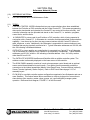
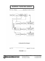
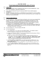
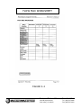
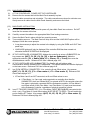
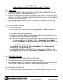
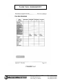
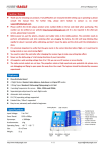
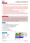
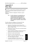
Technical Bulletin Bulletin No. Subject: Page 1 of 18 Product Applicability: Engineering Release: Engineering Release Date: Distribution: 020 Rev B Main Panel Replacement Checklist Evolution and DX2 Controllers R. A. Olson June 20, 2003 APPROVED FOR GENERAL RELEASE TABLE OF CONTENTS Section Description Page 1 Reference Material, Terms 2 2 Central System Users, NON-Flow Max, NO ET Tracker 4 3 Central System Users, Flow Max and/or ET Tracker 6 4 NON-Central System Users, NON-Flow Max, NO ET Tracker 11 5 NON-Central System Users, Flow Max and/or ET Tracker 13 6 Cable Connections, Evolution and DX2 Controllers 18 Technical Bulletin 020 Sheet 1 of 18 3910-B Royal Avenue Simi Valley, CA 93063 Tel: (805) 527-4498 Fax: (805) 527-2813 SECTION ONE Reference Material/Terms (1.0) REFERENCE MATERIAL: ¾ DX2 User’s Manual and Field Maintenance Guide. (1.1) TERMS: ¾ CENTRAL CONTROL MODE indicates that two-way communications have been established between the Evolution or DX2 controller and the Central Control PC. This means programming data can be downloaded and uploaded, the Central PC can control all functions remotely, vital controller information can be uploaded and stored on the Central PC, i.e. statistics, programs, current limits, and flow limits. ¾ A SUBMASTER is a term used for an Evolution or DX2 controller, which is being operated in conjunction with a Central PC. A Submaster is a controller that has specialized communications capability. It can be set up for direct two-way communications with the Central PC either via radio, telephone, or wire. Additionally, the Submaster is responsible for communications to any Satellites that may be physically connected to it. Typical Submaster addresses are XXX-00, with the –00 indicating a Submaster address. ¾ SATELLITE is a term used for any controller that is connected to a Central PC or a Submaster. Yes, a Submaster is a Satellite, but a Satellite is not necessarily a Submaster. Typical Satellite addresses are XXX-XX, with the –XX indicating a Satellite address. Also, -XX is any number other than 00 from 01-99. ¾ The SATELLITE ADDRESS identifies each Satellite within a multiple controller system. The address number is alternately displayed on the base screen of the controller. ¾ The MAIN PANEL assembly consists of a main microprocessor control board and an optional sensor control board (attached to main board). Four cables from this assembly provide the connections to the internal assemblies (Master Valve/Pump/Power, Communications (optional), Sensor Terminal (optional), Station Output). Refer to DX2 User’s Manual page 2-12, for assembly layout. ¾ FLOW MAX is a multiple controller system configuration comprised of one Submaster and one or more Satellites. This unique feature allows controllers to utilize a single point of connection to share devices (flow sensors, master valves, pumps, etc.) and intelligently manage system operation. Reference block diagram, FIGURE 1-1 of this Document. Technical Bulletin 020 Sheet 2 of 18 3910-B Royal Avenue Simi Valley, CA 93063 Tel: (805) 527-4498 Fax: (805) 527-2813 EXAMPLE: FLOW MAX GROUP FIGURE 1-1 Technical Bulletin 020 Sheet 3 of 18 3910-B Royal Avenue Simi Valley, CA 93063 Tel: (805) 527-4498 Fax: (805) 527-2813 SECTION TWO Central System Users, NON-Flow Max Group, NO ET Tracker (2.0) CONDITIONS: 01. PANEL REPLACEMENT FOR A SUBMASTER OR SATELLITE (NON-SUBMASTER): NONFLOW MAX GROUP, NO ET TRACKER CONNECTED. 02. UNLESS OTHERWISE SPECIFIED, ALL REFERENCES WILL BE MADE TO THE DX2 USER’S MANUAL. KEY PRESS SEQUENCES FOR THE DX2 CONTROLLER WILL BE THE SAME FOR THE EVOLUTION CONTROLLER. (2.1) 01. PRIOR TO PANEL REMOVAL: AT THE CENTRAL PC. With a Central System configuration, prior to removing a controller Main Panel for replacement, it is important to upload the existing data to the Central PC, IF THE CENTRAL PC HAS COMMUNICATIONS WITH THE CONTROLLER BEING SERVICED. This will insure the most current information resides at Central. For the controller in question upload STATISTICS, PROGRAMS, CURRENT LIMITS, and FLOW LIMITS. WARNING: IF A SYSTEM USES BASIC ET, DO NOT UPLOAD PROGRAM INFORMATION FROM THE FIELD CONTROLLER. THE ADJUSTED STATION RUN TIME WILL BECOME THE “BASE” RUN TIME IF UPLOADED. 02. AT THE CENTRAL PC. Place the Satellite OFF-LINE. 03. AT THE CONTROLLER. ¾ Is it a SUBMASTER? If so, make note of the Satellite Address. The address number is alternately displayed on the base screen with the program number. ¾ Is a FLOW METER(s) CONNECTED? If so, make note of the K and Offset values. Key presses: QUIT, F1, F5, F5, F2, [F1 = Flow meter 1, F2 = Flow meter 2]. Reference DX2 User’s Manual page 4-51. ¾ Is a MOISTURE SENSOR(s) CONNECTED? If so, make note of the Trip Point(s). Key presses: QUIT, F1, F5, F5, F1, [F1 = Review M sensors]. Reference DX2 User’s Manual page 4-46. (2.2) MAIN PANEL REMOVAL: 01. AT THE CONTROLLER. POWER OFF THE CONTROLLER. 02. Remove the four screws that hold the Main Panel assembly in place. 03. Note the cable connections and orientation. The cable connections are keyed to minimize error. Gently remove all cables from the Main Panel Assembly and remove the board. (2.3) MAIN PANEL INSTALLATION: 01. AT THE CONTROLLER. With controller power off, place Main Panel into enclosure. Do NOT insert the four screws at this time. 02. Carefully connect the cables to the appropriate Main Panel mating connectors. Technical Bulletin 020 Sheet 4 of 18 3910-B Royal Avenue Simi Valley, CA 93063 Tel: (805) 527-4498 Fax: (805) 527-2813 03. Secure the Main Panel in place with the four mounting screws. 04. Turn controller power on. The Main Panel will chirp once and the LANGUAGE (Start-up Initialization) options are displayed. Follow the screen prompts. ¾ It may be necessary to adjust the contrast in the display by using the DARK and LIGHT front panel keys. ¾ LANGUAGE options will only be displayed if the controller RAM has been zeroed out; otherwise the BASE SCREEN will be displayed. 05. IS THE CONTROLLER A SUBMASTER? Address the controller to act as a SUBMASTER, the key presses are: QUIT , F1, F5, F4, F4, [F2 = Acts as Submaster]. Make the appropriate selection [F1 = Radio/Wire, F2 = Phone, F3 = Trunk], then enter the desired address number. Reference DX2 User’s Manual page 4-43. 06. IS THE CONTROLLER A NOT A SUBMASTER? The Satellite will self address when communication with the SUBMASTER is established. The satellite address will then be displayed on the base screen. Reference DX2 User’s Manual page 4-43. 07. Is a FLOW METER(s) CONNECTED? If so, enter the K and Offset values. Key presses: QUIT, F1, F5, F5, F2, [F1 = Flow meter 1, F2 = Flow meter 2]. Reference DX2 User’s Manual page 4-51. 08. Is a MOISTURE SENSOR(s) CONNECTED? If so, enter the Trip Point(s). Key presses: QUIT, F1, F5, F5, F1, [F1 = Review M sensors]. Reference DX2 User’s Manual page 4-46. 09. AT THE CENTRAL PC. Place the controller in question ON-LINE. 10. AT THE CENTRAL PC. For the controller in question SET SATELLITE TIME AND NAME. 11. AT THE CENTRAL PC. For the controller in question download PROGRAMS, CURRENT LIMITS, and FLOW LIMITS. 12. AT THE CENTRAL PC. If the controller serviced is connected to a weather station, the RAIN and WIND limits must be downloaded to the controller. Technical Bulletin 020 Sheet 5 of 18 3910-B Royal Avenue Simi Valley, CA 93063 Tel: (805) 527-4498 Fax: (805) 527-2813 SECTION THREE Central System Users, Flow Max Group, and/or ET Tracker (3.0) CONDITIONS: 01. PANEL REPLACEMENT FOR A SUBMASTER OR SATELLITE (NON-SUBMASTER): FLOW MAX GROUP AND/OR ET TRACKER CONNECTED. 02. FOR A DETAILED DESCRIPTION OF FLOW MAX, REFER TO DX2 USER’S MANUAL APPENDIX F. 03. UNLESS OTHERWISE SPECIFIED, ALL REFERENCES WILL BE MADE TO THE DX2 USER’S MANUAL. KEY PRESS SEQUENCES FOR THE DX2 CONTROLLER WILL BE THE SAME FOR THE EVOLUTION CONTROLLER. (3.1) 01. PRIOR TO PANEL REMOVAL: AT THE CENTRAL PC. With a Central System configuration, prior to removing a controller Main Panel for replacement, it is important to upload the existing data to the Central PC, IF THE CENTRAL PC HAS COMMUNICATIONS WITH THE CONTROLLER BEING SERVICED. This will insure the most current information resides at Central. For the controller in question upload STATISTICS, PROGRAMS, CURRENT LIMITS, and FLOW LIMITS. WARNING: IF A SYSTEM USES BASIC ET, DO NOT UPLOAD PROGRAM INFORMATION FROM THE FIELD CONTROLLER. THE ADJUSTED STATION RUN TIME WILL BECOME THE “BASE” RUN TIME IF UPLOADED. 02. AT THE CENTRAL PC. Place the Satellite OFF-LINE. 03. AT THE CONTROLLER. ¾ Is it a SUBMASTER? If so, make note of the Satellite Address. The address number is alternately displayed on the base screen with the program number. ¾ Is it part of a FLOW MAX GROUP? This will require clarification from the end user. Refer to FIGURES 3-1 and 3-2 of this document for guidance. Make note of which devices are shared and which controller the shared devices are connected to. Key presses: QUIT, F1, F5, F4, F4, F3, [F1 = Share Flow, Pump & MV]. Take note, is Flow Meter 1 connected to this Clock? Press the Down Arrow Key to view and note which devices are connected to this Clock. ¾ Is a FLOW METER(s) CONNECTED? If so, make note of the K and Offset values. Key presses: QUIT, F1, F5, F5, F2, [F1 = Flow meter 1, F2 = Flow meter 2]. Reference DX2 User’s Manual page 4-51. ¾ Is a MOISTURE SENSOR(s) CONNECTED? If so, make note of the Trip Point(s). Key presses: QUIT, F1, F5, F5, F1, [F1 = Review M sensors]. Reference DX2 User’s Manual page 4-46. Technical Bulletin 020 Sheet 6 of 18 3910-B Royal Avenue Simi Valley, CA 93063 Tel: (805) 527-4498 Fax: (805) 527-2813 EXAMPLE: FLOW MAX WORKSHEET FIGURE 3-1 Technical Bulletin 020 Sheet 7 of 18 3910-B Royal Avenue Simi Valley, CA 93063 Tel: (805) 527-4498 Fax: (805) 527-2813 FLOW MAX WORKSHEET FIGURE 3-2 Technical Bulletin 020 Sheet 8 of 18 3910-B Royal Avenue Simi Valley, CA 93063 Tel: (805) 527-4498 Fax: (805) 527-2813 (3.2) MAIN PANEL REMOVAL: 01. AT THE CONTROLLER. POWER OFF THE CONTROLLER. 02. Remove the four screws that hold the Main Panel assembly in place. 03. Note the cable connections and orientation. The cable connections are keyed to minimize error. Gently remove all cables from the Main Panel Assembly and remove the board. (3.3) MAIN PANEL INSTALLATION: 01. AT THE CONTROLLER. With controller power off, place Main Panel into enclosure. Do NOT insert the four screws at this time. 02. Carefully connect the cables to the appropriate Main Panel mating connectors. 03. Secure the Main Panel in place with the four mounting screws. 04. Turn controller power on. The Main Panel will chirp once and the LANGUAGE options will be displayed, follow the screen prompts. ¾ It may be necessary to adjust the contrast in the display by using the DARK and LIGHT front panel keys. ¾ LANGUAGE options will only be displayed if the controller RAM has been zeroed out; otherwise the BASE SCREEN will be displayed. 05. IS THE CONTROLLER A SUBMASTER? Address the controller to act as a SUBMASTER, the key presses are: QUIT, F1, F5, F4, F4, [F2 = Acts as Submaster]. Make the appropriate selection [F1 = Radio/Wire, F2 = Phone, F3 = Trunk], then enter the desired address number. Reference DX2 User’s Manual page 4-43. 06. IS THE CONTROLLER NOT A SUBMASTER? The Satellite will self address when communication with the SUBMASTER is established. The satellite address will then be displayed on the base screen. Reference DX2 User’s Manual page 4-43. 07. Is a FLOW METER(s) CONNECTED? If so, enter the K and Offset values. Key presses: QUIT, F1, F5, F5, F2, [F1 = Flow meter 1, F2 = Flow meter 2]. Reference DX2 User’s Manual page 4-51. ¾ If Flow Meter 1and 2 are NOT connected, set K and Offset values to zero. If Flow Meter 1 or 2 are used, and connected to a controller other than the SUBMASTER, the K and Offsets MUST be entered at BOTH the controller where the flow meter is physically connected AND the Submaster controller. All Flow Meter K and Offset values of both Flow Meter 1 and Flow Meter 2 (if used) must be entered at the Submaster Controller, regardless of physical connection location. 08. Is an ET TRACKER CONNECTED? If so, Flow Meter 2 MUST BE ENABLED (connected to this clock = yes). Flow Meter 2, K and Offset values, MUST BE SET TO ZERO. This will enable the port to read the ET Tracker. Key presses: QUIT, F1, F5, F5, F2, [F2 = Flow meter 2]. Reference DX2 User’s Manual page 4-51. Technical Bulletin 020 Sheet 9 of 18 3910-B Royal Avenue Simi Valley, CA 93063 Tel: (805) 527-4498 Fax: (805) 527-2813 09. A Controller that is part of a FLOW MAX GROUP MUST BE INITIALIZED AS A FLOW MAX PARTICIPANT. Is it a SUBMASTER? (Reference DX2 User’s Manual page F-13). ¾ Select the devices that are to be shared in the Flow Max operation. Key presses: QUIT, F1, F5, F4, F4, F3, [F1 = SHARE FLOW, PUMP & MV]. Is it a SATELLITE (Non-Submaster)? (Reference DX2 User’s Manual page F-21). ¾ If it is a NON-Flow Max Participant, no Flow Max set-up is required. To assure or confirm the controller is not in Flow Max, set it in the “NORMAL MODE” with Key presses: QUIT, F1, F5, F4, F4, F3, [F3 = Normal Mode]. The Base Screen returns. ¾ If it is a Flow Max Participant? Select the devices that are to be shared in the Flow Max operation. Key presses: QUIT, F1, F5, F4, F4, F3, [F1 Share Flow, Pump & MV]. 10. Is a MOISTURE SENSOR(s) CONNECTED? If so, enter the Trip Point(s). Key presses: QUIT, F1, F5, F5, F1, [F1 = Review M sensors]. Reference DX2 User’s Manual page 4-46. 11. AT THE CENTRAL PC. ¾ Place the controller in question ON-LINE. ¾ For the controller in question SET SATELLITE TIME AND NAME. ¾ For the controller in question download PROGRAMS, CURRENT LIMITS, and FLOW LIMITS. ¾ AT THE CENTRAL PC. If the controller serviced is connected to a weather station, the RAIN and WIND limits must be downloaded to the controller. Technical Bulletin 020 Sheet 10 of 18 3910-B Royal Avenue Simi Valley, CA 93063 Tel: (805) 527-4498 Fax: (805) 527-2813 SECTION FOUR NON-Central System Users, NON-Flow Max, NO ET Tracker (4.0) CONDITIONS: 01. PANEL REPLACEMENT FOR A STAND ALONE CONTROLLER: NO FLOW MAX GROUP AND NO ET TRACKER CONNECTED. 02. UNLESS OTHERWISE SPECIFIED, ALL REFERENCES WILL BE MADE TO THE DX2 USER’S MANUAL. KEY PRESS SEQUENCES FOR THE DX2 CONTROLLER WILL BE THE SAME FOR THE EVOLUTION CONTROLLER. 03. REFER TO DX2 USERS MANUAL PAGES 4-1 THROUGH 4-6 FOR SETUP OPTIONS AND SYSTEM DEFAULTS. (4.1) 01. PRIOR TO PANEL REMOVAL: AT THE CONTROLLER. ¾ If necessary, review and note all programs. ¾ Is a FLOW METER(s) CONNECTED? If so, make note of the K and Offset values. Key presses: QUIT, F1, F5, F5, F2, [F1 = Flow meter 1, F2 = Flow meter 2]. Reference DX2 User’s Manual page 4-51. ¾ Is a MOISTURE SENSOR(s) CONNECTED? If so, make note of the Trip Point(s). Key presses: QUIT, F1, F5, F5, F1, [F1 = Review M sensors]. Reference DX2 User’s Manual page 4-46. (4.2) MAIN PANEL REMOVAL: 01. AT THE CONTROLLER. POWER OFF THE CONTROLLER. 02. Remove the four screws that hold the Main Panel assembly in place. 03. Note the cable connections and orientation. The cable connections are keyed to minimize error. Gently remove all cables from the Main Panel Assembly and remove the board. (4.3) MAIN PANEL INSTALLATION: 01. AT THE CONTROLLER. With controller power off, place Main Panel into enclosure. Do NOT insert the four screws at this time. 02. Carefully connect the cables to the appropriate Main Panel mating connectors. 03. Secure the Main Panel in place with the four mounting screws. 04. Turn controller power on. The Main Panel will chirp once and the LANGUAGE options will be displayed, follow the screen prompts. ¾ It may be necessary to adjust the contrast in the display by using the DARK and LIGHT front panel keys. ¾ LANGUAGE options will only be displayed if the controller RAM has been zeroed out; otherwise the BASE SCREEN will be displayed. 05. Is a FLOW METER(s) CONNECTED? If so, enter the K and Offset values. Key presses: Technical Bulletin 020 Sheet 11 of 18 3910-B Royal Avenue Simi Valley, CA 93063 Tel: (805) 527-4498 Fax: (805) 527-2813 QUIT, F1, F5, F5, F2, [F1 = Flow meter 1, F2 = Flow meter 2]. Reference DX2 User’s Manual page 4-51. 06. Is a MOISTURE SENSOR(s) CONNECTED? If so, enter the Trip Point(s). Key presses: QUIT, F1, F5, F5, F1, [F1 = Review M sensors]. Reference DX2 User’s Manual page 4-46. 07. ENTER PROGRAM(S) INTO CONTROLLER. This will require clarification from the End User. 08. OPTIONAL: If the panel being installed is a temporary loaner while the original is being repaired, it may not be necessary to utilize the electrical or flow check feature. If however the panel being installed is the permanent, both the station electrical and flow values must be manually entered or relearned and ENABLE the feature. When Flow Sensing is used, Station Flows, Main Line Flow and Unscheduled Flow Allowance must each be entered. DX2 CONTROLLERS. ESTABLISH CURRENT and/or FLOW LIMITS. This will require clarification from the End User. Key presses: QUIT, F1, F5, F3, F3, [F1 = RUN AUTO LIMITS, F2 = SET LIMIT (%)]. Reference DX2 User’s Manual page 4-28. ¾ EVOLUTION CONTROLLERS. Manually set CURRENT and/or FLOW LIMITS for each station. Key presses: QUIT, F1, F5, F3, [F1 = ENABLE/DISABLE LIMIT CHECKING, F2 = MANUAL LIMITS/STATION SETUP]. Technical Bulletin 020 Sheet 12 of 18 3910-B Royal Avenue Simi Valley, CA 93063 Tel: (805) 527-4498 Fax: (805) 527-2813 SECTION FIVE NON-Central System Users, Flow Max, and or ET Tracker (5.0) CONDITIONS: 01. PANEL REPLACEMENT FOR A SUBMASTER OR SATELLITE (NON-SUBMASTER): FLOW MAX GROUP AND/OR ET TRACKER CONNECTED. 02. UNLESS OTHERWISE SPECIFIED, ALL REFERENCES WILL BE MADE TO THE DX2 USER’S MANUAL. KEY PRESS SEQUENCES FOR THE DX2 CONTROLLER WILL BE THE SAME FOR THE EVOLUTION CONTROLLER. 03. REFER TO DX2 USERS MANUAL PAGES 4-1 THROUGH 4-6 FOR SETUP OPTIONS AND SYSTEM DEFAULTS. (5.1) 01. PRIOR TO PANEL REMOVAL: AT THE CONTROLLER. ¾ Is it a SUBMASTER? If so, make note of the Satellite Address. The address number is alternately displayed on the base screen with the program number. ¾ If necessary, review and note all programs. ¾ Is it part of a FLOW MAX GROUP? This will require clarification from the end user. Refer to FIGURES 5-1 and 5-2 of this document for guidance. Make note of which devices are shared and which devices are connected to this controller. Key presses: QUIT, F1, F5, F4, F4, F3, [F1 = Share Flow, Pump & MV]. Take note, is Flow Meter 1 connected to this Clock? Press the Down Arrow Key to view and note which devices are connected to this Clock. ¾ Is a FLOW METER(s) CONNECTED? If so, make note of the K and Offset values. Key presses: QUIT, F1, F5, F5, F2, [F1 = Flow meter 1, F2 = Flow meter 2]. Reference DX2 User’s Manual page 4-51. ¾ Is a MOISTURE SENSOR(s) CONNECTED? If so, make note of the Trip Point(s). Key presses: QUIT, F1, F5, F5, F1, [F1 = Review M sensors]. Reference DX2 User’s Manual page 4-46. (5.2) MAIN PANEL REMOVAL: 01. AT THE CONTROLLER. POWER OFF THE CONTROLLER. 02. Remove the four screws that hold the Main Panel assembly in place. 03. Note the cable connections and orientation. The cable connections are keyed to minimize error. Gently remove all cables from the Main Panel Assembly and remove the board. (5.3) MAIN PANEL INSTALLATION: 01. AT THE CONTROLLER. With controller power off, place Main Panel into enclosure. Do NOT insert the four screws at this time. 02. Carefully connect the cables to the appropriate Main Panel mating connectors. Technical Bulletin 020 Sheet 13 of 18 3910-B Royal Avenue Simi Valley, CA 93063 Tel: (805) 527-4498 Fax: (805) 527-2813 03. Secure the Main Panel in place with the four mounting screws. 04. Turn controller power on. The Main Panel will chirp once and the LANGUAGE options will be displayed, follow the screen prompts. ¾ It may be necessary to adjust the contrast in the display by using the DARK and LIGHT front panel keys. ¾ LANGUAGE options will only be displayed if the controller RAM has been zeroed out; otherwise the BASE SCREEN will be displayed. 05. IS THE CONTROLLER A SUBMASTER? Address the controller to act as a SUBMASTER, the key presses are: QUIT, F1, F5, F4, F4, [F2 = Acts as Submaster]. Make the appropriate selection [F1 = Radio/Wire, F2 = Phone, F3 = Trunk], then enter the desired address number. Reference DX2 User’s Manual page 4-43. 06. IS THE CONTROLLER A SATELLITE (not a Submaster)? No Address setup is required. The Satellite will self address and the base screen will be displayed. Reference DX2 User’s Manual page 4-43. 07. Is a FLOW METER(s) CONNECTED? If so, enter the K and Offset values. Key presses: QUIT, F1, F5, F5, F2, [F1 = Flow meter 1, F2 = Flow meter 2]. Reference DX2 User’s Manual page 4-51. 08. Is an ET TRACKER CONNECTED? If so, Flow Meter 2 MUST BE ENABLED (connected to this clock = yes). Flow Meter 2, K and Offset values, MUST BE SET TO ZERO. This will enable the port to read the ET Tracker. Key presses: QUIT, F1, F5, F5, F2, [F2 = Flow meter 2]. Reference DX2 User’s Manual page 4-51. 09. Is the Controller part of a FLOW MAX GROUP? This will require clarification from the End User. ¾ Is it a SUBMASTER? (Reference DX2 User’s Manual page F-13). ¾ Select the devices that are to be shared in the Flow Max operation. Key presses: QUIT, F1, F5, F4, F4, F3, [F1 = SHARE FLOW, PUMP & MV]. ¾ Set Flow Meter K and Offset values All Flow Meter K and Offset values of both Flow Meter 1 and Flow Meter 2 (if used) must be entered at the Submaster Controller, regardless of physical connection location. The values must also be entered at the Satellite Controllers that are physically connected to Flow Meter 1 or 2. ¾ Is it a SATELLITE? (Reference DX2 User’s Manual page F-21). ¾ If it is a NON-Flow Max Participant, no Flow Max set-up is required. To assure or confirm the controller is not in Flow Max, set it in the “NORMAL MODE” with Key presses: QUIT, F1, F5, F4, F4, F3, [F3 = Normal Mode]. The Base Screen returns. ¾ Is it a Participant? Select the devices that are to be shared in the Flow Max operation. Key presses: QUIT, F1, F5, F4, F4, F3, [F1 Share Flow, Pump & MV]. 10. Is a MOISTURE SENSOR(s) CONNECTED? If so, enter the Trip Point(s). Key presses: QUIT, F1, F5, F5, F1, [F1 = Review M sensors]. Reference DX2 User’s Manual page 4-46. 11. ENTER PROGRAM(S) INTO CONTROLLER. This will require clarification from the End User. 12. OPTIONAL: If the panel being installed is a temporary loaner while the original is being repaired, Technical Bulletin 020 Sheet 14 of 18 3910-B Royal Avenue Simi Valley, CA 93063 Tel: (805) 527-4498 Fax: (805) 527-2813 it may not be necessary to utilize the electrical or flow check feature. If however the panel being installed is the permanent, both the station electrical and flow values must be manually entered or relearned and ENABLE the feature. When Flow Sensing is used, Station Flows, Main Line Flow and Unscheduled Flow Allowance must each be entered. DX2 CONTROLLERS. ESTABLISH CURRENT and/or FLOW LIMITS. This will require clarification from the End User. Key presses: QUIT, F1, F5, F3, F3, [F1 = RUN AUTO LIMITS, F2 = SET LIMIT (%)]. Reference DX2 User’s Manual page 4-28. ¾ EVOLUTION CONTROLLERS. Manually set CURRENT and/or FLOW LIMITS for each station. Key presses: QUIT, F1, F5, F3, [F1 = ENABLE/DISABLE LIMIT CHECKING, F2 = MANUAL LIMITS/STATION SETUP]. Technical Bulletin 020 Sheet 15 of 18 3910-B Royal Avenue Simi Valley, CA 93063 Tel: (805) 527-4498 Fax: (805) 527-2813 EXAMPLE: FLOW MAX WORKSHEET FIGURE 5-1 Technical Bulletin 020 Sheet 16 of 18 3910-B Royal Avenue Simi Valley, CA 93063 Tel: (805) 527-4498 Fax: (805) 527-2813 FLOW MAX WORKSHEET FIGURE 5-2 Technical Bulletin 020 Sheet 17 of 18 3910-B Royal Avenue Simi Valley, CA 93063 Tel: (805) 527-4498 Fax: (805) 527-2813 SECTION SIX Cable Connections, Evolution and DX2 Controllers DX2 Controller All four connectors are keyed. 1 “RED” – Main Panel to Master Valve Board. 2 “WHITE” – Main Panel to Output Board. 3 “FLOW” – Optional, Sensor Board to Sensor Terminal Board. 1 2 4 3 4 “COMM” – Main Panel to Comm Hardwire Board. Evolution Controller All four connectors are keyed. Pin 1, Stripe 1 1 “COMM” - Main Panel to Satellite Board. 2 – “STATIONS” Main Panel to Output Board, 1-24. 3 “FLOW” – Optional, Sensor Board to Sensor Terminal Board. 4 “STATIONS” – Main Panel to Output Board, 25-48. 2 3 4 END OF BULLETIN Technical Bulletin 020 Sheet 18 of 18 3910-B Royal Avenue Simi Valley, CA 93063 Tel: (805) 527-4498 Fax: (805) 527-2813