1
™
Laminar Mass Flowmeters
User Manual
Series: OFS
Firmware Revision 5.79
UNIVERSAL FLOW MONITORS, INC.
1755 East Nine Mile Road
PO Box 249
Hazel Park, MI 48030-0249
TEL (248) 542-9635 FAX (248) 398-4274
http://www.flowmeters.com
FSMAN.6 081214
Page 1
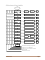
TABLE OF CONTENTS
PROPRIETARY NOTICE ............................................................................................................. 3
NAMEPLATE EXAMPLE ............................................................................................................ 4
GENERAL SPECIFICATIONS .................................................................................................... 5
ELECTRICAL SPECIFICATIONS ............................................................................................... 6
OPERATION ................................................................................................................................. 7
Figure 1. Laminar Flow Illustration ........................................................................................... 7
APPLICATIONS ........................................................................................................................... 7
Using FlowStream at Varying Temperatures ............................................................................. 7
Using FlowStream with Different Gases ................................................................................... 8
Reference Conditions for Mass Flow Measurement .................................................................. 8
WIRING DIAGRAM ..................................................................................................................... 9
Wiring for 4-20mA Transmitters ............................................................................................... 9
Figure 2. Standard Transmitter Wiring ...................................................................................... 9
Figure 3. Required Supply Voltage vs. Loop Resistance ......................................................... 10
Hazardous Environment Wiring............................................................................................... 10
Figure 4. Intrinsically Safe Installation ................................................................................... 11
Wiring for Voltage Output Models .......................................................................................... 12
Figure 5. Voltage Output Wiring ............................................................................................. 12
Wiring for Frequency or Pulse Output Models ........................................................................ 13
Figure 6. Frequency and Pulse Output Wiring......................................................................... 13
POWER-UP ................................................................................................................................. 14
LCD READOUT .......................................................................................................................... 14
Flow Rate ................................................................................................................................. 15
Totalizer ................................................................................................................................... 15
Pressure .................................................................................................................................... 17
Temperature ............................................................................................................................. 19
USER MENU ............................................................................................................................... 20
Select Response Time .............................................................................................................. 22
Sampling Delay ........................................................................................................................ 23
Signal Averaging ...................................................................................................................... 24
Set High Flow Alarm ............................................................................................................... 26
Set Low Flow Alarm ................................................................................................................ 28
Tare (Re-Zero) the Flowmeter ................................................................................................. 29
Scaling the Output Span ........................................................................................................... 31
Selecting the Gas ...................................................................................................................... 32
Totalizer ON/OFF .................................................................................................................... 33
Pulse Output Setting ................................................................................................................. 34
Checking Battery Voltage ........................................................................................................ 35
SPECIAL FEATURES ................................................................................................................ 36
Factory Reset ............................................................................................................................ 36
Low Supply Voltage Indicator ................................................................................................. 37
Diagnostic Mode ...................................................................................................................... 38
HOW TO ORDER A SINGLE-GAS FLOWMETER ................................................................. 40
DIMENSIONS OF OFS SERIES ................................................................................................ 42
RETURN MATERIAL AUTHORIZATION ............................................................................... 43
WARRANTY INFORMATION .................................................................................................. 45
FSMAN.6 081214
Page 2
PROPRIETARY NOTICE
The information contained in this publication is derived in part from proprietary and patented
data. This information has been prepared for the express purpose of assisting in installation,
operation, and maintenance of the instruments described herein. Publication of this information
does not convey any rights of use or reproduction other than in connection with the installation,
operation and maintenance of the equipment described herein. Universal Flow Monitors, Inc.
reserves the right to change the information contained in this publication at any time and without
prior notice.
Serial numbers are formatted as YY MM ID 000
YY = year, MM = month, ID = product identifier, 000 through 999 = three-digit sequential
number.
FSMAN.6 081214
Page 3
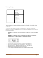
NAMEPLATE EXAMPLE
Firmware revision
Model Code
Intrinsically Safe
flowmeters must include
“X2A” or “Z2A” in the
Model Code
The Intrinsically Safe flow transmitters have the following label:
FSMAN.6 081214
Page 4
GENERAL SPECIFICATIONS
Flow Ranges:
500 SCCM full-scale to 1,000 SLPM full-scale
1 SCFH full-scale to 2,100 SCFH full-scale
Turndown Ratio:
100:1
Maximum Operating Pressure:
100 PSIG
Burst Pressure:
200 PSIG
Pressure Effect on Accuracy:
Less than 0.03% F.S. / PSI
Maximum Operating Temperature: 176 °F (80 ºC)
Minimum Operating Temperature: -13 °F (-25 ºC)
Temperature Effect on Accuracy:
Less than 0.03% F.S./ °F
Maximum Pressure Drop:
1.5 PSI at F.S. flow (from inlet port to outlet port)
Process Connections:
1/4”-3/8”-1/2”-3/4” NPT female
Wetted Parts
Sensors:
Glass-filled nylon, alumina-based ceramic, silicon, gold,
epoxy
Flow Body Internals:
Anodized aluminum, Viton, stainless steel
Enclosure Rating:
Type 4
Display:
4-digit LCD digital display, 0.35" high
Approvals:
CE, CSA, Intrinsic Safety (all classes and divisions) with
proper zener barrier
FSMAN.6 081214
Page 5
ELECTRICAL SPECIFICATIONS
Accuracy (Including Linearity and Repeatability)
Flow:
± 1% of full-scale for flowmeters sized from 15-566 SLPM
(31-1200 SCFH) of Air
± 2% of full-scale for flowmeters sized for lower than
15 SLPM (30 SCFH) of Air
± 2% of full-scale for flowmeters sized for higher than
566 SLPM (1201 SCFH) of Air
Pressure:
± 1 PSI (See Note 1)
Temperature:
± 3 °F
Totalizer:
± 0.25% of full-scale (in addition to flow accuracy)
Output Signal
Analog:
4-20 mA (2-wire loop powered)
0-5 V, 0-10 V, 1-5 V
0-5 V Bi-directional (2.5 V = 0 flow)
Frequency:
0-1000 Hz, 200-1200 Hz
0-3V signal amplitude
Pulse:
1,250-5,000 pulses/minute, user selectable
0-3V pulse amplitude
2 msec pulse width
Response Time:
5 – 100 msec (step response), user selectable
Alarms:
2 independent open-collector outputs (high/low flow rate)
with corresponding LEDs
30VDC at 50 mA
Open-Collector Rating:
Electrical Connection:
Supply Voltage:
Supply Current:
4- or 7-conductor shielded pigtail cable
10–30 VDC (Standard), 12-24 VDC (Intrinsically Safe)
7.2-9 VDC for battery-operated units (See Note 2)
22 mA @ F.S. flow (includes over-range) for 4-20 mA
loop-powered transmitters
5 mA for voltage, frequency, and pulse outputs
3.5 mA for battery-operated units (See Note 2)
Note 1: Pressure, temperature, and totalizer are only displayed on the LCD. No output signal is
available for these parameters.
Note 2: Battery-operated units require a standard 9V alkaline battery and will operate for over 100 hours
continuously. An On/Off switch allows the user to turn the power off, thus conserving the battery life.
These flowmeters have no output signal.
FSMAN.6 081214
Page 6
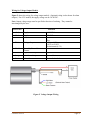
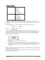
OPERATION
FlowStream flowmeters accurately measure the mass flow rate of most gases. The flow rate is
determined by measuring the pressure drop across a unique internal restriction, known as
Laminar Flow Element (LFE). The restriction is designed such that the gas molecules are forced
into moving in parallel paths along the entire length of the passage for the entire range of
operation of the device. Unlike other pressure-flow measuring devices, the relationship between
pressure drop and flow is linear in laminar flowmeters.
FlowStream mass flowmeters utilize an absolute pressure sensor along with a temperature
sensor to compensate for density variations of the gas. When combined with the differential
pressure (volumetric flow) output, the mass flow rate of the gas can be determined.
Figure 1. Laminar Flow Illustration
APPLICATIONS
FlowStream flowmeters are designed to work with non-corrosive, non-ionic, clean, dry gases
only. Introduction of liquids to the internal sensors will damage the unit, and the repair is not
covered under warranty. Relative humidity of the gas can be as high as 100%, as long as proper
installation guarantees that no internal condensation will occur. A 50-micron filter and/or dryer
may be required for some applications.
Using FlowStream at Varying Temperatures
Even though FlowStream flowmeters measure true mass flow, rapid variations in ambient
and/or gas temperature may affect performance. This is due to the time lag of the internal
temperature sensor and the slow heating and cooling of the flowmeter body. It is highly
recommended that through proper installation the following two objectives be met:
There be minimal difference between gas temperature and ambient temperature;
Rapid temperature variations be avoided.
FSMAN.6 081214
Page 7
The internal temperature sensor is located above the inlet port, very close to where the gas enters
the meter. This ensures accurate measurement of the gas temperature. However, because the
temperature sensor is embedded inside the flowmeter body, if ambient temperature is different
from gas temperature, there would be a discrepancy between what the sensor reads and the true
gas temperature. The flowmeter body would track ambient temperature while gas temperature
would heat/cool the body at a different rate.
Likewise, if temperature variation is rapid, the flowmeter body may not follow it quickly enough
due to the mass of the metal flow chamber, which in turn would result in inaccurate
measurement of gas temperature.
For optimal performance, always allow two to four hours from the time the ambient and gas
temperatures are stabilized to when the first flowmeter reading is taken.
Using FlowStream with Different Gases
FlowStream flowmeters can easily be used to measure the flow rate of other gases, as long as
the gas compatibility criteria are observed. For example, a flowmeter that is factory-calibrated
for air can be used to measure the flow of Argon. (Consult Factory for additional information.)
Reference Conditions for Mass Flow Measurement
Although the correct units for mass are expressed in grams, kilograms, etc., it has become
somewhat standard that mass flow rate is specified in SLPM (standard liters per minute), SCFH
(standard cubic feet per hour) or other similar units.
This means that the mass flow rate is calculated by normalizing the volumetric flow rate to some
standard temperature and pressure (STP). By knowing the gas density at that STP, one can
determine the mass flow rate in grams per minute, kilograms per hour, etc. STP is usually
specified at sea level conditions; however, no single standard exists for this convention. UFM
uses STP of 70° F and 14.7 PSIA.
Note: If used outside the parameters specified in this manual, the proper operation of the
flowmeter cannot be guaranteed.
FSMAN.6 081214
Page 8
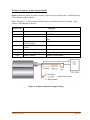
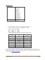
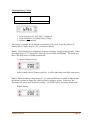
WIRING DIAGRAM
Wiring for 4-20mA Transmitters
Figure 2 shows a typical 2-wire, 4-20mA transmitter wiring for use with FlowStream
flowmeters. Maximum loop resistance is related to the available supply voltage. Since the
flowmeter requires 10 volts to operate, the voltage drop across the loop resistance at full-scale
flow output (20mA) must be added in to determine the minimum supply voltage. For example,
if a 100-ohm resistor is used to convert the current signal to voltage, the voltage drop across the
resistor will be 0.4-2 volts for 4-20 mA, respectively. Minimum required loop voltage in this
case is 12 volts, as shown. Likewise, the voltage drop for a 250-ohm resistor is 1-5 volts,
requiring a minimum of 15 volts supply. Please refer to the graph in Figure 3.
Wire Color
Red
Supply +
Black
Brown
Supply Tare
White
Shield
Not Used
Internally Grounded to
Chassis
High Alarm Output
Blue
Orange
Green
Low Alarm Output
Alarm Common
Function
12-30VDC (Standard)
12-24 VDC (Intrinsically Safe)
DC GND
Short to GND for 5 seconds to tare at zero
flow
Do not connect
Open-collector
Open-collector
Emitter for both alarms
Figure 2. Standard Transmitter Wiring
(DO NOT Use for Intrinsically Safe Applications)
Note: Shield wire (shown as gray) may be connected to an external chassis ground to improve
electrical noise immunity. However, care must be taken not to connect this ground to signal
ground.
FSMAN.6 081214
Page 9
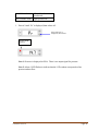
Figure 3. Required Supply Voltage vs. Loop Resistance
Hazardous Environment Wiring
Intrinsically Safe wiring must be installed in accordance with Article 504 of NEC, ANSI NPF 70
and Control Drawing Number 7577, Revision 00 (Figure 4, below). The transmitter approval
by the Canadian Standards Association for installation in Hazardous environments is based on
installation through an Intrinsic Safety Barrier.
The Transmitter when wired through the I.S. Barrier is suitable for use in:
CLASS I GROUPS A, B, C & D
CLASS II GROUPS E, F & G
CLASS III HAZARDOUS LOCATIONS
Earth Ground of the I.S. Barrier must be connected to the earth ground of the AC feeder supply.
The resistance between Intrinsically Safe ground terminals and A.C. Earth ground must be less
than one Ohm. (UFM suggested I.S. Barrier R.Stahl 9001/01-280-075-10, UFM part number
8140).
The Power Supply voltage is limited to 24 VDC Max. The Power Supply Control Unit must not
use or be able to generate more than 250 volts. The Maximum Load that can be put on the
system is 250 Ohms.
All repairs on the Flow Transmitter should be accomplished at the factory because any
substitution of components may impair Intrinsic Safety.
FSMAN.6 081214
Page 10
Figure 4. Intrinsically Safe Installation
FSMAN.6 081214
Page 11
Wiring for Voltage Output Models
Figure 5 shows the wiring for voltage output models. (Optional wiring is also shown for alarm
outputs.) For 0-5V models, the supply voltage can be 10-30VDC.
Note: Output voltage range must be specified at the time of ordering. They cannot be
interchanged by the user.
Wire Color
Red
Supply +
Black
Brown
Supply Tare
White
Voltage Output
Shield
Internally Grounded to
Chassis
High Alarm Output
Low Alarm Output
Alarm Common
Blue
Orange
Green
Function
15-30VDC
DC GND
Short to GND for 5 seconds to tare at zero
flow
0-5V (or 1-5V)
0-10V (or 2-10V)
Bi-directional (0-5V)
Open-collector
Open-collector
Emitter for both alarms
Figure 5. Voltage Output Wiring
FSMAN.6 081214
Page 12
Wiring for Frequency or Pulse Output Models
Figure 6 shows the wiring for either frequency output or pulse output models. (Optional wiring
is also shown for alarm outputs.)
Note: “Frequency” or “Pulse Output” model must be specified at the time of ordering. They
cannot be interchanged by the user.
Wire Color
Red
Supply +
Black
Brown
Supply Tare
White
Frequency Output
Or Pulse Output
Internally Grounded to
Chassis
High Alarm Output
Low Alarm Output
Alarm Common
Shield
Blue
Orange
Green
Function
10-30VDC
DC GND
Short to GND for 5 seconds to tare at zero
flow
0-3V signal amplitude
Open-collector
Open-collector
Emitter for both alarms
Figure 6. Frequency and Pulse Output Wiring
FSMAN.6 081214
Page 13
POWER-UP
At power-up, the following appears on the LCD:
Firmware Revision 5.67 or Higher
Electronics Revision
It takes 2 seconds for these messages to be displayed, during which time the output of the
flowmeter is clamped at zero flow. After 2 seconds, the output signal starts indicating actual
flow.
LCD READOUT
If the flowmeter is configured for High-Speed (HS) response, the LCD only shows “run”. No
other parameters can be viewed on the LCD in this mode.
LCD in HS mode:
In Low-Speed (LS) (see Select Response Time) the user can toggle the readout between flow
rate, total, pressure, and temperature. When in Run mode, use A2 pushbutton to select. The
selection is stored in the internal memory, so if power is removed from the flowmeter it
remembers the selection next time it is powered up.
Note: The output signal and alarms always indicate “flow rate”.
FSMAN.6 081214
Page 14
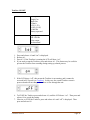
Flow Rate
Available with:
Not Available with:
All models in LowSpeed mode
High-Speed mode
In Run Mode:
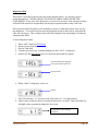
1. Press A2 (or press and release a few times) until “rATE” is displayed.
2. Release A2. The flowmeter will display Flow Rate.
Press until “rATE”
shown then release
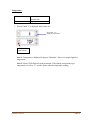
Totalizer
Available with:
Not Available with:
Low-Speed
Single-Gas
Multi-Gas
4-20mA
0-5V (1-5V)
0-10V (2-10V)
0-1000 Hz
Battery-operated
200-1200 Hz
Pulse output
Bi-directional
Note: In order to view the Totalizer, it must first be “Started” in the User Menu (see Totalizer
ON/OFF).
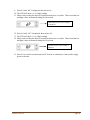
1. The first time A2 is pressed, “rATE” is displayed as shown above, to indicate the current
selection. Press A2 again until “tot” is displayed.
2. Release A2.
Press until “tot” shown
then release
FSMAN.6 081214
Page 15
Viewing the Totalizer
The Totalizer value is displayed in three 3-digit groups (9 digits total) as shown.
This is the low-order 3 digits (000 through 999), as indicated by the one horizontal bar
on the left of the LCD. The low-order digits may or may not include a decimal point.
This depends on the displayed units in rate mode. Maximum Totalizer reading is
therefore scaled according to the decimal point position and is between 999,999.999 and
999,999,999.
3. Use A1 to toggle between the different Totalizer digit groups.
Press and release
This is the middle-order 3 digits (1,000 through 999,000), as indicated by the two
horizontal bars on the left of the LCD.
Press and release
This is the high-order 3 digits (1,000,000 through 999,000,000), as indicated by the three
horizontal bars on the left of the LCD.
Note 1: Output signal is always indicative of Flow Rate regardless of what the LCD is
displaying.
Note 2: The Totalizer is updated every 100 msec. Therefore, flow variations that happen
faster that 100 msec cannot be accumulated accurately. In order to meet the specified
accuracy of the Totalizer, flow must be steady within each 100 msec sampling window
(preferably even longer, to ensure each sample is captured accurately).
Note 3: Rate Alarms are active in the background and their corresponding LED lights up
when alarm condition is encountered. Response time for the Rate Alarms is 50 msec,
since the flowmeter is running in Low-Speed mode.
Note 4: The Totalizer reading is saved once every 5 minutes in the non-volatile memory.
This means that the maximum error due to power loss can be up to the last 5 minutes of
operation. This is also the response time for the Rate Alarms. The reading can be saved
by the user at any time (e.g., the end of a batch) by pressing A2 (“tot” is displayed),
followed by pressing A1 (while still holding A2).
FSMAN.6 081214
Page 16
When the Totalizer readout exceeds 9 digits (inclusive of the decimal places), the display shows
two lower vertical bars on the left side to indicate overflow. The leftmost display segments will
look like the following patterns:
Low order digits in overflow:
Middle order digits in overflow:
High order digits in overflow:
The count shown on the display remains accurate until a second overflow occurs (2,000,000,000
is
reached). In this case the vertical bar does not reflect how many times overflow has occurred.
Resetting the Totalizer
Press A2 until “tot” is displayed. (You must be in “Totalizer” mode first.)
Hold A2 for 5 seconds. Four rotating zeroes start to appear.
Continue holding A2 until all zeros are completed and “tot” is displayed again. Then
release A2.
Note: If A2 is released before the rotating zeroes are completed, the resetting of the Totalizer is
ignored.
Hold until all 4 zeroes
are completed
Pressure
FSMAN.6 081214
Page 17
Available with:
Not Available with:
All models in LowSpeed mode
High-Speed mode
1. Press A2 until “Pr” is displayed, then release A2.
Press until “Pr” is
displayed, then release
Pressure mode
indicator
Note 1: Pressure is displayed in PSIA. There is no output signal for pressure.
Note 2: Alarm 1 LED flashes to indicate that the LCD readout corresponds to line
pressure and not flow.
FSMAN.6 081214
Page 18
Temperature
Available with:
Not Available with:
All models in LowSpeed mode
High-Speed mode
1. Press A2 until “t” is displayed, then release A2.
Press until “t” is
displayed, then release
Temperature
mode indicator
Note 1: Temperature is displayed in degrees Fahrenheit. There is no output signal for
temperature.
Note 2: Alarm 2 LED flashes to indicate that the LCD readout corresponds to gas
temperature, as well as “F” which is shown after the temperature reading.
FSMAN.6 081214
Page 19
USER MENU
The following features and options can be selected, viewed and changed by the user.
Response Time – Select between high-speed (5 msec) and low-speed (up to 50 msec)
Sample Delay – Sampling delay from 0-9 msec
Signal Averaging – Array size for the moving average (1-16 samples)
High Flow Alarm – From 0–100% of full-scale
Low Flow Alarm – From 0-100% of full-scale
Tare – Correct small zero-shift errors
Span – Scale the output signal from 25-120%
Gas – Select one of 8 common gases
Totalizer – Start/Stop the Totalizer
Pulse Output – Select pulse rate and width
Battery – Monitor battery voltage
General Notes:
These features apply to flowmeters with a built-in LCD display. For units without the
display consult the factory to check what options can be preset at the factory.
Two pushbuttons are provided for user interface. A1 (ADJUST) pushbutton is used to scroll
through the user menu and its options, and A2 (ENT/SET) is used to select the feature of
interest.
When the flowmeter is in high-speed (HS) mode, the LCD displays “run” and no other
parameters can be viewed. This is for achieving the fastest possible response time (5 msec)
and minimizing the CPU overhead.
FSMAN.6 081214
Page 20
OFS Menu Structure and Feature Compatibility
Run
Mode
A1
X
X
Response Time
X
A2
High Speed
A1
Low Speed
A2
Done
A1
(Low-Speed settings)
Sampling Delay
A1
(Low-Speed settings)
Signal Averaging
A2
A2
Add additional delay of 0-9 msec
Select array size of 1-16
A2
A2
Done
Done
A1
X
X
X
X
High Flow Alarm
A1
X
X
X
X
Low Flow Alarm
A1
X
X
X
X
X
Re-Zero
A1
X
Span
A1
X
X
X
X
X
Select Gas
A1
X
X
Start Totalizer
A1
X
Pulse Parameters
A1
X
Battery Status
A2
A2
A2
A2
A2
A2
A2
A2
Use A1 and A2 to set value
Use A1 and A2 to set value
A2
A2
Use A1 to select Gas1 - Gas8
On
A1
Done
Done
Hold A2 for 5 seconds
Use A1 and A2 to set value
Done
A2
A2
Done
Done
A2
Off
Use A1 to select pulses per minute
Done
A2
Hold A2 to display battery voltage
Done
Done
A1
End
200-1200 Hz, Pulse output, Low-speed only
4-20mA, 0-5V, 0-10V, High-speed
4-20mA, 0-5V, 0-10V, 0-1000 Hz, Low-speed
Battery-operated
Bi-directional (0-5V only)
FSMAN.6 081214
Page 21
Select Response Time
Available with:
High-Speed
Low-Speed
Single-Gas
Multi-Gas
4-20mA
0-5V (1-5V)
0-10V (2-10V)
Bi-directional
Not Available with:
0-1000 Hz
200-1200 Hz
Pulse output
Battery-operated
Press and release
1.
2.
3.
4.
5.
Press A1 until “rESP” is displayed, then release A1.
Press A2. Either “HS” (high-speed) or “LS” is displayed, showing the current setting.
Press A1 to toggle between the two options.
Press A2 to select the desired selection.
The LCD will show “End” and the unit returns to normal operation.
If “HS” is selected, the LCD will only show “run”. The analog output is updated as
quickly as a single flow sample is acquired, which is about every 5 milliseconds.
If “LS” is selected, the LCD will show the flow rate, and the flow signal is averaged
to provide a smoother output. The step response for “low-speed” output is
determined by the sample delay (if any) and the signal averaging array size. These
values are user selectable (see the next section).
FSMAN.6 081214
Page 22
Sampling Delay
Available with:
Low-Speed
Single-Gas
Multi-Gas
4-20mA
0-5V (1-5V)
0-10V (2-10V)
Bi-directional
Not Available with:
0-1000 Hz
200-1200 Hz
Pulse output
Battery-operated
Press and release
1. Press A1 until “dELY” is displayed, then release A1.
2. Press A2. The current setting will be shown. This is a value between 0-9, in
milliseconds.
3. Press A1 to toggle between the values.
4. Press A2 to select the desired selection.
5. The LCD will show “End” and the unit returns to normal operation.
Each flow sample takes about every 5 milliseconds to complete. This is an additional
delay that is inserted after the flow sample to slow down the flowmeter response
time. In some applications where the flowmeter is used in a feedback loop to
regulate flow, if the response time is too fast the system starts oscillating.
The delay setting is only used when the meter operates in “LS” (Low-Speed) mode.
It is ignored in “HS” (High-Speed) mode.
FSMAN.6 081214
Page 23
Signal Averaging
Available with:
Low-Speed
Single-Gas
Multi-Gas
4-20mA
0-5V (1-5V)
0-10V (2-10V)
Bi-directional
Not Available with:
0-1000 Hz
200-1200 Hz
Pulse output
Battery-operated
Press and release
1. Press A1 until “AvG” is displayed, then release A1.
2. Press A2. The current setting will be shown. This is a value between 1-16, and indicates
how many flow samples are averaged (moving average window size) to calculate the
output.
3. Press A1 to toggle between the values.
4. Press A2 to select the desired selection.
5. The LCD will show “End” and the unit returns to normal operation.
Each flow sample takes about every 5 milliseconds to complete. The “AvG” value is
the size of the moving average array, allowing for 1 to 16 samples to be averaged
when the output is calculated. This is used to slow down the flowmeter response
time, and provide a smoother output. In some applications where the flowmeter is
used in a feedback loop to regulate flow, if the response time is too fast the system
starts oscillating.
The delay setting is only used when the meter operates in “LS” (Low-Speed) mode.
It is ignored in “HS” (High-Speed) mode.
FSMAN.6 081214
Page 24
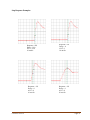
Step Response Examples:
Response = HS
Delay = N/A
AVG = N/A
10 ms/div
Response = LS
Delay = 0
AVG = 4
10 ms/div
FSMAN.6 081214
Response = LS
Delay = 0
AVG = 1
10 ms/div
Response = LS
Delay = 9
AVG = 8
50 ms/div
Page 25
Set High Flow Alarm
Available with:
Not Available with:
High-Speed
Low-Speed
Single-Gas
Multi-Gas
4-20mA
0-5V (1-5V)
0-10V (2-10V)
0-1000 Hz
200-1200 Hz
Pulse output
Battery-operated
Bi-directional
Press and release
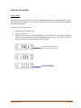
1. Press A1 until “HFLo” is displayed, then release A1.
2. Press A2 and hold until the setpoint is displayed on the LCD (in this example, high flow
alarm is set at 80.0). Then release A2. The first digit starts blinking.
Press and hold
3. Use A1 to change the blinking digit. The setpoint is changed one digit at a time. A1
increments each individual digit (9 rolls over back to 0), while A2 is used for recording
the new digit value and selecting the next digit.
4. Use A2 to record the new value and select the second
digit.
Press and release to
change the value
Press to record the
new value
Press and hold after the last digit
5. After the last digit is set, continue holding A2 until “SEt” is displayed. If you want to
change the first digit again, do not hold A2. Momentarily press and release A2 and the
first digit starts blinking again.
6. When finished recording the new setpoint (“SEt” is displayed), release A2.
FSMAN.6 081214
Page 26
Release
Note 1: Valid setpoint range is 0-100% of full-scale flow. If the alarm value is set higher than
full-scale, it is clamped at full-scale upon exiting this menu.
Note 2: To disable the alarm, set its value to zero.
Note 3: The red ALARM 1 LED comes on when flow exceeds this setpoint. This LED is in
series with the drive circuit for the high-alarm open-collector output, meaning that the output
transistor is active whenever this LED is on. Some models do not have any external wiring that
connects to the alarm transistor (see Model Codes).
In this example, the high alarm had been set for 80.0; therefore, the red LED was activated when
flow reached 80.1. The LED turns off when flow < setpoint – hysteresis. Hysteresis is 5% of fullscale.
FSMAN.6 081214
Page 27
Set Low Flow Alarm
Available with:
Not Available with:
High-Speed
Low-Speed
Single-Gas
Multi-Gas
4-20mA
0-5V (1-5V)
0-10V (2-10V)
0-1000 Hz
200-1200 Hz
Pulse output
Battery-operated
Bi-directional
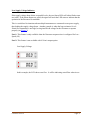
1. Press A1 (or press and release a few times) until “LFLo” is displayed, then release A1.
Use the same method as explained above (“Set High Flow Alarm”) to set the low flow alarm as
follows:
2. Press A2 and hold until the setpoint is displayed on the LCD. Then release A2. The first
digit starts blinking.
3. Use A1 to change the blinking digit (9 rolls over back to 0).
4. Use A2 to select different digits.
5. After the last digit, momentarily press and release A2 to go back to the first digit again, or
continue holding A2 until “SEt” is displayed. Then release A2.
Note 1: Valid setpoint range is 0-100% of full-scale flow. If the alarm value is set higher than
full-scale, it is clamped at full-scale upon exiting this menu.
Note 2: To disable the alarm, set its value to zero.
Note 3: The red ALARM 2 LED comes on when flow drops below this setpoint. This LED is in
series with the drive circuit for the low-alarm open-collector output, meaning that the output
transistor is active whenever this LED is on. Some models do not have any external wiring that
connects to the alarm transistor (see Model Codes). The LED turns off when flow > setpoint +
hysteresis. Hysteresis is 5% of full-scale.
FSMAN.6 081214
Page 28
Tare (Re-Zero) the Flowmeter
Available with:
ALL MODELS
Important Notice: Because of the excellent sensitivity of these flowmeters, small readings may
actually indicate leaks in the system and should not be zeroed out. Ensure that there is no flow
through the device when attempting to tare the output.
The flowmeter can be tared in two ways:
by using the pushbuttons;
by grounding the Tare wire (the brown wire).
USING pushbuttons:
1. Press and release A1 until The LCD will show “Tare”:
2. Press and hold A2. The display will show “0000” after 5 seconds. This is shown as 4
rotating zeros on the LCD:
Hold until all 4 zeroes
are completed
“SEt” is then displayed.
Note 1: If A2 is released before all 4 zeros are completed, the tare request will be ignored.
Note 2: There is a limit within which the flowmeter can be tared. This limit is about 8% of fullscale. The actual shift in zero reading is typically far less drastic (in the order of 1-2%). If the
flowmeter indicates a reading higher than 8% of full-scale, it cannot be tared because this may
indicate that either there is flow through the device or an internal component has physically
failed. If you attempt to tare under this condition, the flowmeter displays “EEEE” on the LCD
instead of “SEt”. This is a visual indicator that the tare process encountered an error. This error
condition applies to both pushbutton and external wire taring.
Note 3: There is an internal memory check that monitors for proper recording of the zero value.
This includes a series of redundant memory locations that serve as backup. If an error occurs
(i.e., a recorded value does not match what was written to the memory), the flowmeter ignores
the new setting and reverts back to factory calibration. Such an error is displayed as “E1E2”
following a tare attempt, and also at power-up. If you encounter this error message, please
contact the factory for further assistance.
FSMAN.6 081214
Page 29
USING the external Tare wire:
Refer to Figure 2, Figure 5 or Figure 6, showing the proper connection between the external
Tare wire and ground. Short this wire to ground for a minimum of 5 seconds. “Tare” will be
displayed as soon as the wire is grounded and remains displayed until the internal tare is
successfully completed, upon which time “SEt” will be displayed. If the ground connection is
removed from the Tare wire in less than 5 seconds, the tare request is ignored and “SEt” will
NOT be displayed. This time delay feature is implemented to prevent accidental grounding of
the external wire. Notes 1 and 2 above also apply to external taring.
Note 4: When taring is taking place (either through the pushbuttons or the external wire), the
flowmeter output signal is “frozen”. The level at which the output is frozen depends on what the
most recent flow reading was, prior to activating the tare input. If you encounter a problem
where the flowmeter output does not respond to changes in flow, check for problems in the Tare
wiring (shorts to ground, etc.), or a malfunctioning pushbutton (A1).
Note 5: When not in use, the Tare wire MUST either be left floating (open-circuit), or taken
high to the power supply voltage via a 10K pull-up resistor. When taring is not needed, DO
NOT hold the Tare line at voltages below the supply voltage! This may leave the tare circuitry
partially activated, thus resulting in “frozen” or erroneous outputs.
Note 6: The external Tare wire is designed to be a momentary signal of 5 to10 seconds in
duration. Grounding this signal for long periods of time (over many minutes) may cause an
internal damage to the tare circuitry when the supply voltage is above 18V.
FSMAN.6 081214
Page 30
Scaling the Output Span
Available with:
Low-Speed
Single-Gas
Multi-Gas
4-20mA
0-5V (1-5V)
0-10V (2-10V)
Not Available with:
High-Speed
0-1000 Hz
200-1200 Hz
Pulse Output
Battery-Operated
Bi-directional
This feature is for scaling the analog output to a value other than the factory calibration. For
example, for a 100 SLPM flowmeter with 4-20mA output, the output can be spanned to 20mA at
75 SLPM.
The acceptable range is 25-120% of full-scale. The formula for the span factor is:
Full-Scale x Factor = Full Span
Example:
100 SLPM x 75% = 20mA
75 SLPM = 20mA
Values above 100% mean that the output signal is attenuated. This may be desirable in cases
where the flowmeter is over-ranged up to 20% of full-scale. When the span factor is changed
from its factory setting, there will be some loss of linearity, accuracy, and output resolution.
Please consult the factory for details.
1. Press and release A1 until “SPAn” is displayed.
2. Release A1.
3. Use A1 and A2 (as shown under “Set High Flow Alarm”) to type in a value that is
between 25.0 and 120.0. This is the “Factor” percentage as shown in the above formula.
4. When the desired factor is entered, press and hold A2 until “SEt” is displayed. Then
release A2.
Note 1: The LCD always displays true flow in the factory-calibrated units. Spanning the output
does not affect the LCD readout.
Note 2: If the Span Factor is set to a value that is outside the 25.0 – 120.0 range, it is changed
back to 100.0 upon exiting this menu.
FSMAN.6 081214
Page 31
Selecting the Gas
Available with:
Not Available with:
High-Speed
Low-Speed
Single-Gas
Multi-Gas
4-20mA
0-5V (1-5V)
0-10V (2-10V)
0-1000 Hz
200-1200 Hz
Pulse output
Battery-operated
Bi-directional
Single-Gas
1. Press and release A1 until “GAS” is displayed. Then release A1.
2. Press A2, the current selection will be displayed as shown
3. Use A1 to change the gas number according to the following list:
Number
Gas
1
Air
Additional Accuracy
Degradation
0%
2
Argon
0.2%
3
CO2
1%
4
Helium
1%
5
Hydrogen
1%
6
Methane
1%
7
Nitrogen
0.2%
8
Oxygen
1%
Note: There is additional degradation of accuracy when gases other than Air are selected. This
is shown in the column next to each gas and must be added to the standard accuracy of the unit,
as shown under Electrical Specifications.
FSMAN.6 081214
Page 32
Totalizer ON/OFF
Available with:
Low-Speed
Single-Gas
Multi-Gas
4-20mA
0-5V (1-5V)
0-10V (2-10V)
0-1000 Hz
Battery-operated
Not Available with:
High-Speed
200-1200 Hz
Pulse output
Bi-directional
1.
2.
3.
4.
Press and release A1 until “tot” is displayed.
Release A1.
Press A2. If the Totalizer is running the LCD will show “on”.
If you need to stop the Totalizer, press and release A1. This feature may be useful to
prevent the Totalizer from counting during setting up a batch process.
5. If the LCD shows “off”, this means the Totalizer is not running, and it cannot be
accessed in RUN mode (see Totalizer). In this case, the current Totalizer count is
preserved and will not change when there is flow through the unit.
6. To START the Totalizer press and release A1, until the LCD shows “on”. Then press and
release A2 to record the setting.
7. Likewise, to STOP the Totalizer, press and release A1 until “off” is displayed. Then
press and release A2.
FSMAN.6 081214
Page 33
Pulse Output Setting
Available with:
Low-Speed
Single-Gas
Multi-Gas
Pulse Output
Not Available with:
High-Speed
200-1200 Hz
4-20mA
0-5V (1-5V)
0-10V (2-10V)
0-100 Hz
Battery-operated
Bi-directional
The pulse output rate is typically 5000 pulse per minute for all models. Pulse width is 2 msec
for all models.
To convert the above numbers to “pulses per standard liters,” “pulses per standard cubic
centimeters” or “pulse per standard cubic feet” divide the pulse count by the full-scale value of
the particular flowmeter.
Example 1: The output for a 100 SLPM flowmeter is 5000/100 = 50 pulses per standard
liters.
Example 2: The output for a 500 SCFH flowmeter is 300,000/500 = 600 pulses per
standard cubic feet. (5,000 x 60 minutes = 300,000 pulses per hour)
1.
2.
3.
4.
5.
To set the pulse rate, press and release A1 until “PULS” is displayed.
Press A2, the current pulse count will be displayed. Then release A2.
Press and release A1. The displayed choices are 5000, 2500, and 1250.
When the desired value is selected, press A2 to record it.
“SEt” is displayed and the unit returns to RUN mode with the new setting.
FSMAN.6 081214
Page 34
Checking Battery Voltage
Available with:
Battery-operated
Not Available with:
All Other Models
1. Press and release A1 until “bAtt” is displayed.
2. Press and hold A2 to read the battery voltage.
3. Release A2 when done.
This feature is intended for checking how much battery life is left. Typically, when a 9V
alkaline battery voltage drops to 7.5V, it should be replaced.
Note 1: The microprocessor continuously monitors the battery voltage during operation. When
the voltage drops to 7.5V during RUN mode, the two red LEDs start blinking. This means you
have a few more hours of reliable operation left.
3-5 hours of battery life left:
In this example, the LCD shows zero flow. It will be indicating actual flow when in use.
Note 2: When the battery voltage drops to 7.1V, both red LEDs stay on (solid) to indicate that
the internal circuitry no longer has a stable reference voltage to operate. In this case, the
flowmeter will start to show erroneous readings. You MUST replace the battery at this point.
Replace battery:
FSMAN.6 081214
Page 35
SPECIAL FEATURES
Factory Reset
This feature is provided to override all user-configurable parameters, and replacing them with
the original factory settings. It is a useful tool if the user is unsure how he/she has programmed
some of the parameters.
To enter the Factory Reset mode:
1. Remove power from the unit.
2. Press A2 and hold.
3. Turn the power back on. Continue holding A2 until “FACt rSEt” is displayed, followed
by 4 sets of horizontal bars. This will take approximately 10 seconds. Then release A2.
4. The unit will then reset itself and start in RUN mode
Press and hold before applying
power, then turn the power on
Continue holding until
all digits are completed
FSMAN.6 081214
Page 36
Low Supply Voltage Indicator
If the supply voltage drops below acceptable levels, the two Alarm LEDs will either flash or turn
on (solid). If the alarm outputs are wired, the signal will track the LED states to indicate that the
operation of the flowmeter is unreliable.
This is a useful tool in situations when multiple instruments are connected to one power supply,
thus loading the supply voltage down. Another example is when the loop resistance for a 420mA flow transmitter is too high, leaving insufficient voltage for the flowmeter to operate
properly (see Figure 3).
Note 1: This feature is only available when the flowmeter response time is configured for LowSpeed (LS).
Note 2: This feature is not available with 4-20 mA output option.
Low Supply Voltage:
In this example, the LCD shows zero flow. It will be indicating actual flow when in use.
FSMAN.6 081214
Page 37
Diagnostic Mode
This feature is provided to observe the state of the internal sensors. It is strictly a passive
troubleshooting tool. THERE ARE NO USER-SERVICEABLE PARTS INSIDE THE
FLOWMETER. If any parts of the flowmeter are removed or unscrewed, the warranty becomes
void and UFM assumes no responsibility for the proper operation and/or safety of the unit.
If the operation of the flowmeter seems unstable or incorrect, contact the factory for a step-bystep diagnostic. You will be asked to enter the Diagnostic mode as show below, and report the
value for each sensor. This would provide sufficient information for determining if an internal
component has failed.
To enter Diagnostic mode:
1.
2.
3.
4.
5.
Enter “rAtE” mode (see Flow Rate).
Remove power from the unit.
Press A2 and hold.
Turn the power back on. Continue holding A2 until “FACt” is displayed.
Release A2 and immediately press A1 before the horizontal bars appear.
Press and hold before applying
power, then turn the power on
Press and hold
6. When “dIAG” is displayed, release A1.
Release
7. The LCD will show “t1” for one second, followed by a 3- or 4-digit reading.
8. Observe this reading for about 10 seconds to make sure it is stable. Then record the low
and high values encountered during the 10 seconds.
Temperature sensor reading is
displayed
FSMAN.6 081214
Page 38
9. Press A2 until “dP” is displayed, then release A2.
10. The LCD will show a 3- or 4-digit reading.
11. Observe this reading for about 10 seconds to make sure it is stable. Then record the low
and high values encountered during the 10 seconds.
Differential pressure sensor reading
is displayed
12. Press A2 until “AP” is displayed, then release A2.
13. The LCD will show a 3- or 4-digit reading.
14. Observe this reading for about 10 seconds to make sure it is stable. Then record the low
and high values encountered during the 10 seconds.
Absolute pressure sensor reading is
displayed
15. Press A2 to reset the unit and return to RUN mode or, alternately, remove and re-apply
power to the unit.
FSMAN.6 081214
Page 39
HOW TO ORDER A SINGLE-GAS FLOWMETER
FSMAN.6 081214
Page 40
FSMAN.6 081214
Page 41
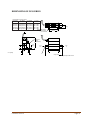
DIMENSIONS OF OFS SERIES
Approximate in inches (mm)
“C” Height
Flow Rate
“H” Height
“P” Port
to Port
Maximum
Overall
Connections
120 SCFH 2.45” [62mm] 0.68” [17mm] 1/4-18 NPT
280 SCFH 2.59” [66mm] 0.93” [24mm] 1/4-18 NPT
520 SCFH 2.98” [76mm] 0.55” [14mm] 3/8-18 NPT
1000 SCFH 3.79” [96mm] 1.09” [28mm] 1/2-14 NPT
1000 SLPM 4.63” [118mm] 1.51” [38mm] 3/4-14 NPT
MOUNTING HOLES
Ø.28 [7.1mm] THRU
(2) PLACES
H
0.36
[9mm]
1.00 [25mm]
3.00
[76mm]
BATTERY
PACK
(OPTIONAL)
FLOW
OUT
FLOW
IN
C
0.75 [19mm]
2.00 [51mm]
2.51 [64mm] BATTERY PACK
FSMAN.6 081214
Page 42
NOTICE
RETURN MATERIAL AUTHORIZATION
Please read the following UFM policy information carefully. By following the
guidelines outlined below you will assist in providing a timely evaluation and
response regarding the status of your flowmeter. UFM evaluates all
AUTHORIZED RETURNED MATERIALS in a timely manner and will promptly
provide notification regarding the status of the related materials and/or a written
quotation indicating the total charges and description of the necessary repairs.
1. All returns must have a RMA form completed by the customer.
2. Any meter returned that was previously in service must have the OSHA requirements completed and a
MSDS included where applicable.
3. An RMA number will only be issued when UFM has received a copy of the completed RMA form and any
applicable MSDS.
4. A “Return Goods” shipping label (located in the back of the Instruction Manual) must be used for returning
materials to UFM.
5. Returned goods must be shipped prepaid or they will be rejected.
REPAIRABLE MATERIAL
Written or verbal authorization to proceed with the repair under an assigned
Purchase Order must be received within 30 days of repair quotation. If the unit(s) is
repaired, the $90.00 evaluation charge will be applied to the quoted repair costs. If no
repairs are authorized within this 30-day period, the customer will be billed $90.00 plus
shipping charges and the materials will be returned to the customer.
NON-REPAIRABLE MATERIAL
If materials are found non-repairable, a written notice that the material is non-repairable
will be provided to the customer by UFM. If no disposition to scrap or return the material
is received from the customer within 30 days, non-repairable material will be scrapped
and the customer will be billed the $90.00 evaluation charge. If a UFM replacement
unit is purchased within 30 days of non-repairable condition notice, the $90.00
evaluation fee will be waived. The return of non-repairable materials may be ordered
by a customer Purchase Order; shipping and handling charges will be assumed by
customer.
RETURN FOR RESTOCK
All goods returned for restock adjustment must be:
A. New and unused.
B. Returned to the factory within ONE YEAR of date of original shipment.
C. Returned through the distributor where the goods were originally purchased.
D. Returned material will be subject to an evaluation charge of $90.00.
The customer will be advised of the restocking adjustment for all restockable goods.
Upon customer’s acceptance of the restocking adjustment, the $90.00 evaluation fee will
be waived and UFM will issue a credit to the customer. The customer will be advised of
any non-restockable goods and will be charged the $90.00 evaluation fee plus any
shipping charges if goods are returned to the customer.
If no disposition is received by UFM within 30 days, the goods will be scrapped and the
$90.00 evaluation fee will be billed.
WARRANTY RETURNS
Warranty returns must be shipped prepaid to UFM. UFM will review the goods and
advise the customer of the evaluation and validity of the warranty claim. Valid warranty
claims will be repaired or replaced at no charge. No evaluation fee will be charged
for repairs made under warranty. Return shipping costs will be prepaid by UFM. Should
UFM determine returned material not to be defective under the provisions of UFM’s
standard warranty, the customer will be advised of needed repairs and associated
costs. All materials returned for warranty repair that are determined not to have a
valid warranty claim will be subject to the “Repairable Material” policy outlined above.
WARRANTY INFORMATION
1) ACCEPTANCE AND INTEGRATION CLAUSE: This Sales Order Acknowledgment and the sales order
information that Universal Flow Monitors, Inc. ("Universal") attaches to or associates with it (herein "Acknowledgment"),
constitutes an acceptance by Universal of an offer by the buyer upon the conditions and terms and at the prices stated in
this Acknowledgment. The Acknowledgment contains the entire understanding of Universal and the buyer regarding the
subject matter of said Acknowledgment. This Acknowledgment may only be modified by a written agreement signed
by the party against whom enforcement is sought.
2) WAIVER: Waiver by Universal of any default(s) by the buyer shall not constitute waiver by Universal of any of the
conditions of the agreement between Universal and the buyer as set forth hereunder with respect to any further or subsequent
default by the buyer.
3) FORCE MAJEURE: Universal shall not be responsible for failure or delays in deliveries due to fire, strikes,
breakdowns, acts of God, failure of carriers, inability to secure required materials, or other causes beyond Universal's
control. Buyer waives any claims for damage arising by virtue of delay in delivery of material by Universal.
4) LIMITED WARRANTY:
(a) Warranty. For a period of one year from the date of manufacture, Universal warrants that each product covered by
this Acknowledgment will be free from defects in material and workmanship. In order to qualify for any remedy provided
in this Acknowledgment, buyer must give notice to Universal within the one-year period, return the product to Universal
freight paid and intact with Material Safety Data Sheets covering all substances passing through the product or that form
a residue on the product.
(b) Exclusive Remedy. The buyer's EXCLUSIVE REMEDY for failure of any product to conform to any warranty or
otherwise for any defect is, at Universal's sole option: (i) repair; (ii) replacement; or (iii) refund of the entire purchase
price for the specific product. Without limiting the foregoing, in no case will Universal be liable for de-installation of
any defective product or installation of any repaired or replaced product. THIS REMEDY I S THE EXCLUSIVE
REMEDY AVAILABLE TO THE BUYER OR ANY OTHER PERSON. UNIVERSAL SHALL NOT BE LIABLE FOR
ANY DIRECT, INDIRECT, INCIDENTAL, CONSEQUENTIAL, SPECIAL, PUNITIVE, OR OTHER DAMAGES IN
CONNECTION WITH ANY CAUSE OF ACTION, WHETHER IN CONTRACT, TORT, OR OTHERWISE.
(c) Disclaimer of Other Warranties. The express warranty in this Acknowledgment is in lieu of any other warranty,
express or implied. Without limiting the foregoing, UNIVERSAL DISCLAIMS THE IMPLIED WARRANTY OF
MERCHANTABILITY AND ANY IMPLIED WARRANTY OF FITNESS FOR A PARTICULAR PURPOSE.
(d) Special Note About Fitness for a Particular Purpose. This website and other materials of Universal may place products
into, or display products in, categories according to function, size, construction, materials, or other property. This is for
organizational purposes only and NO PLACEMENT OF ANY PRODUCT IN ANY CATEGORY OR ANY
PRESENTATION OF A PRODUCT IN RELATION TO OTHER PRODUCTS WILL CONSTITUTE A WARRANTY
OF FITNESS FOR A PARTICULAR PURPOSE.
5) PROHIBITED USES: As a condition of the sale of goods or services, buyer will not use, sell, distribute, or otherwise
transfer for use, or permit to be used, sold, distributed, or otherwise transferred any product purchased from Universal
for any of the following uses:
(a) Nuclear Energy Applications. Any application involving, directly or indirectly: (i) exposure of any product to any
hazardous properties of nuclear material; (ii) dependence on the proper functioning of the product for the operation
of a nuclear facility by any person or organization; (iii) use in or for any equipment or device used for the processing,
fabricating or alloying of special nuclear material if, at any time, the total amount of such material on the premises
where such equipment or device is located consists of or contains more than 25 grams of (A) Plutonium (any
isotope) or Uranium 233 or any combination thereof; (B) more than 250 grams of Uranium 235; (iv) use in, or for
the control of any aspect of, any structure, basin, excavation, premises or place prepared or used for the storage or disposal
of waste. The foregoing include, without limitation, any application involving nuclear material contained in spent fuel or
waste that is possessed, handled, used, processed, stored, transported or disposed of, any application related to the
furnishing of services, materials, parts or equipment in connection with the planning, construction, maintenance,
operation or use of any nuclear facility.
(b) Aircraft Applications. Any application involving direct or indirect installation in or on, or use in connection with,
any aircraft or aircraft product.
(c) Definitions. As used in this section, the following definitions apply, whether the terms use initial capitals or not.
"Aircraft" includes powered and non-powered winged aircraft, missiles, spacecraft, and other aeronautical craft or
mechanisms.
"Aircraft product" includes:
(1) Any ground support or control equipment used with any aircraft; (2) Any article designed for installation in or on aircraft;
(3) Any ground handling tools or equipment used with aircraft;
(4) Any aircraft training aids, instructions, manuals, or blueprints;
and
(5) Any engineering, labor or other services involving aircraft. "Hazardous properties" include radioactive, toxic or explosive properties;
"Nuclear facility" means
(a) Any nuclear reactor; or
(b) Any equipment or device designed or used for: (1) Separating the isotopes of uranium or plutonium; (2) Processing or utilizing spent
fuel; or
(3) Handling, processing or packaging waste.
"Nuclear material" means source material, special material or by- product material;
"Nuclear reactor" means any apparatus designed or used to sustain nuclear fission in a self-supporting chain reaction or to contain a critical
mass of fissionable material. "Property damage" includes all forms of radioactive contamination of property.
"Source material," "special nuclear material," and "by-product material" have the meanings given them in the Atomic Energy Act of
1954 and any regulation promulgated thereunder, as the same may be amended from time to time.
"Spent Fuel" means any fuel element or fuel component, solid or liquid that has been used or exposed to radiation in a nuclear reactor.
"Waste" means any waste material (1) containing by-product material and (2) resulting from the operation by any person or
organization of any nuclear facility.


![UFM-30CTL Operation manual[PDF:4.1MB] - FOR](http://vs1.manualzilla.com/store/data/005676883_1-d2048345a5eb1a6d8c39e09dd604009b-150x150.png)