1
OPERATION
MANUAL
UFM-30CTL
Control Card
5th Edition (Version. 5.00 - higher)
Precautions
Important Safety Warnings
[Power]
Stop
Do not place or drop heavy or sharp-edged objects on power cord. A damaged cord
can cause fire or electrical shock hazards. Regularly check power cord for
excessive wear or damage to avoid possible fire / electrical hazards.
[Circuitry Access]
Stop
Do not touch any parts / circuitry with a high heat factor.
Capacitors can retain enough electric charge to cause mild to serious shock, even
after power is disconnected. Capacitors associated with the power supply are
especially hazardous. Avoid contact with any capacitors.
Hazard
Unit should not be operated or stored with cover, panels, and / or casing removed.
Operating unit with circuitry exposed could result in electric shock / fire hazards or
unit malfunction.
[Potential Hazards]
Caution
If abnormal smells or noises are noticed coming from the unit, turn power off
immediately and disconnect power cord to avoid potentially hazardous conditions. If
problems similar to above occur, contact authorized service representative before
attempting to again operate unit.
[Consumables]
Caution
The consumables used in unit must be replaced periodically. For further details on
which parts are consumables and when they should be replaced, refer to the
specifications at the end of the Operation Manual. Since the service life of the
consumables varies greatly depending on the environment in which they are used,
they should be replaced at an early date. For details on replacing the consumables,
contact your dealer.
2
Upon Receipt
Unpacking
The UFM-30CTL modules and their accessories are fully inspected and adjusted prior to
shipment. Operation can be performed immediately upon completing all required connections
and operational settings.
Check your received items against the below packing list. Check to ensure no damage has
occurred during shipment. If damage has occurred, or items are missing, inform your supplier
immediately.
ITEM
QTY
UFM-30CTL
1 set
LAN holder
Module guard
1 set
1
Binding screws
1 set
CD-ROM
REMARKS
Front module 1
Rear module 1
LAN holder (holder and bracket)
Guard plate for securing front module.
Binding screws (M3xL6) x 5
Binding screws (M3xL8) x 2
1
UFM Series user manuals (PDF)
The UFM-30CTL module can be installed into a UF-106B or UF-112 frame.
Trademarks
Microsoft, Windows, Internet Explorer, and Windows Vista are either registered trademarks
or trademarks of Microsoft Corporation in the United States and/or other countries.
Pentium and Intel Core are trademarks of Intel Corporation in the U.S. and/or other countries.
Firefox is a registered trademark of the Mozilla Foundation.
All other trademarks are trademarks or registered trademarks of their respective owners.
3
Table of Contents
1. Prior to Starting ........................................................................................................................... 7
1-1. Welcome .............................................................................................................................. 7
1-2. Features ............................................................................................................................... 7
1-3. PC System Requirements .................................................................................................... 7
2. Panel Descriptions ...................................................................................................................... 8
2-1. Front Panel ........................................................................................................................... 8
2-2. Rear Panel ........................................................................................................................... 8
2-3. Installing the UFM-30CTL into a UF-112 ............................................................................. 9
2-3-1. Installing the Rear Module ............................................................................................ 9
2-3-2. Installing the Front Module ......................................................................................... 10
2-4. Installing the UFM-30CTL into a UF-106B ........................................................................ 11
2-4-1. Installing the Rear Module .......................................................................................... 11
2-4-2. Installing the Front Module ......................................................................................... 11
2-5. FUNCTION Switch Settings ............................................................................................... 12
3. System Configuration ................................................................................................................ 13
3-1. Setting IP Addresses.......................................................................................................... 13
3-2. Basic Connection ............................................................................................................... 14
3-3. Connection including UF-NETRU/DCC-NETOU (LAN1)................................................... 15
4. UFM-30CTL Settings................................................................................................................. 16
4-1. Login and Setup ................................................................................................................. 16
4-2. Displaying UFM-30CTL Information .................................................................................. 18
4-3. Module Selection and Network Settings (UF-112) ............................................................ 19
4-4. Module Selection and Network Settings (UF-106B) .......................................................... 20
4-5. Changing User Account ..................................................................................................... 21
4-6. If You Forgot Your Password or IP Address...................................................................... 21
4-7. Changing SNMP Settings .................................................................................................. 22
4-8. Saving or Loading Parameters .......................................................................................... 23
5. Controlling UFM-30FS/FS-R/FS-DA ......................................................................................... 24
5-1. Module Selection and Page Configuration ........................................................................ 24
5-2. Video Settings (Video) ....................................................................................................... 25
5-3. Audio Settings (Audio) ....................................................................................................... 26
5-3-1. Audio Output Selection (Out Select)........................................................................... 27
5-3-2. Audio Output Gain (Audio Gain) ................................................................................. 28
5-3-3. Audio Output Delay (SDI Delay) ................................................................................. 29
5-3-4. Audio Output Mode (Stereo Mode) ............................................................................. 30
5-3-5. Audio Polarity (Polarity) .............................................................................................. 30
5-3-6. Audio System Settings (Audio System) (FS/FS-R) .................................................... 31
5-3-7. Audio System Settings (Audio System) (FS-DA) ....................................................... 33
5-3-8. Audio Downmix Setting (Downmix) (FS/FS-R) ........................................................... 34
5-3-9. Audio Input Setting (Input Setting) (FS/FS-R) ............................................................ 35
5-3-10. Audio Input Setting (Input Setting) (FS-DA) ............................................................. 37
5-3-11. AES Audio Output Delay Settings (AES Delay) (FS-DA) ......................................... 38
5-3-12. AES Audio Source Selection (AES Setting) (FS-DA)............................................... 39
5-4. System Settings (System).................................................................................................. 40
5-5. Utility Settings (Utility) ........................................................................................................ 42
4
5-5-1. Saving / Loading Parameters..................................................................................... 43
5-6. Status Display (Status) ...................................................................................................... 44
5-6-1. General Status ........................................................................................................... 44
5-6-2. Embedded Audio Status (Detailed Status) (FS/FS-R)............................................... 45
5-7. Trap Settings (Trap) .......................................................................................................... 47
6. Controlling UFM-30DCC........................................................................................................... 48
6-1. Module Selection and Page Configuration (DCC) ............................................................ 48
6-2. System Settings (System) (DCC)...................................................................................... 49
6-2-1. Selecting a Color Corrector in a Dual Channel System............................................. 49
6-2-2. System Settings ......................................................................................................... 50
6-3. Video Settings (Video) (DCC) ........................................................................................... 51
6-3-1. Proc Amp.................................................................................................................... 51
6-3-2. Color Correction ......................................................................................................... 52
6-3-3. Clip Control................................................................................................................. 53
6-4. Utility Settings (Utility) (DCC) ............................................................................................ 54
6-4-1. Saving / Loading Parameters..................................................................................... 55
6-5. Status Display (Status) (DCC) .......................................................................................... 56
6-6. SNMP Trap Settings (DCC) .............................................................................................. 57
7. Controlling UFM-30UDC........................................................................................................... 58
7-1. Module Selection and Page Configuration (UDC) ............................................................ 58
7-2. Video Settings (Input) (UDC) ............................................................................................ 59
7-3. Video Settings (Output) (UDC).......................................................................................... 60
7-4. Aspect Ratio Scale Setting (Scaling) (UDC) ..................................................................... 61
7-5. Utility Settings (Utility) (UDC) ............................................................................................ 62
7-5-1. Saving / Loading Parameters..................................................................................... 62
7-6. Status Display (Status) (UDC) .......................................................................................... 63
8. Controlling UFM-42HDRS/HDRSA .......................................................................................... 64
8-1. Module Selection and Page Configuration (42HDRS) ...................................................... 64
8-2. Crosspoint Switches (CrossPoint) (42HDRS) ................................................................... 65
8-3. Status Display (Status) (42HDRS) .................................................................................... 65
8-4. SNMP Trap Settings (42HDRS) ........................................................................................ 66
9. Controlling UFM-30FRC ........................................................................................................... 67
9-1. Module Selection and Page Configuration (FRC)............................................................. 67
9-2. System Settings (FRC)...................................................................................................... 68
9-3. Video Settings (FRC) ........................................................................................................ 69
9-3-1. Video Process AMP ................................................................................................... 69
9-3-2. FRC Process .............................................................................................................. 70
9-3-3. CVBS Input / Output ................................................................................................... 70
9-3-4. Motion Compensation ................................................................................................ 70
9-3-5. Enhancer .................................................................................................................... 71
9-3-6. Film ............................................................................................................................. 71
9-4. Audio Settings (FRC) ........................................................................................................ 72
9-5. Utility Settings (Utility) (FRC) ............................................................................................ 72
9-5-1. Saving / Loading Parameters..................................................................................... 73
9-6. Status Display (Status) (FRC) ........................................................................................... 74
10. Controlling UFM-30NR ........................................................................................................... 75
5
10-1. Module Selection and Page Configuration (NR).............................................................. 75
10-2. Input Settings (Input) (NR) ............................................................................................... 75
10-3. Output Settings (Outout) (NR) ......................................................................................... 76
10-4. Effect (NR)........................................................................................................................ 77
10-4-1. Noise Reduction........................................................................................................ 77
10-4-2. Enhancer ................................................................................................................... 78
10-4-3. Split ........................................................................................................................... 78
10-5. Utility (NR) ........................................................................................................................ 79
10-5-1. Memory ..................................................................................................................... 79
10-5-2. Saving / Loading Parameters ................................................................................... 79
10-5-3. Trap Setting............................................................................................................... 79
10-6. Status (NR) ...................................................................................................................... 80
11. Monitoring UFM Modules ........................................................................................................ 81
11-1. UFM-30DDA/3DDAEX ..................................................................................................... 81
11-2. UFM-15VEA/15VDA/18VDA ............................................................................................ 82
11-3. UFM-14ADA/18ADA ........................................................................................................ 82
12. Monitoring Using SNMP .......................................................................................................... 83
12-1. Connection (LAN2)........................................................................................................... 83
12-2. SNMP Specifications ....................................................................................................... 83
13. Troubleshooting....................................................................................................................... 85
14. Specifications and Dimensions ............................................................................................... 86
14-1. Specifications ................................................................................................................... 86
14-2. External Dimensions ........................................................................................................ 87
Index .............................................................................................................................................. 88
6
1. Prior to Starting
1-1. Welcome
Congratulations! By purchasing a UFM-30CTL Control Card you have entered the world of
FOR-A and its many innovative products. Thank you for your patronage and we hope you will
turn to FOR-A products again and again to satisfy your video and audio needs.
FOR-A provides a wide range of products, from basic support units to complex system
controllers, which have been increasingly joined by products for computer video-based systems.
Whatever your needs, talk to your FOR-A representative. We will do our best to be of continuing
service to you.
1-2. Features
The UFM-30CTL is a plug-in module that can be installed into UFM frames. The UFM-30CTL
can monitor modules that are installed in the same UFM frame as itself from a web browser or by
using SNMP. Some installed UFM modules such as FA-30FS/FS-R/FS-DA and FA-30UDC can
be controlled remotely via web browser or remote control unit UF-NETRU. A UFM-30DCC that
is installed in the same UFM frame can be remote-controlled via web browser or by using an
operation unit DCC-NETOU.
UFM frame module (installed to UF-106B and UF-112)
Supervision over UFM modules via web browser
Monitoring & Control
UFM-30FS/FS-R/FS-DA
UFM-30DCC
UFM-30UDC
UFM-42HDRS/HDRSA
UFM-30FRC
UFM-30NR
Monitoring
UFM-15VEA
UFM-14/18ADA
UFM-15/18VDA
UFM-30DDA/3DDAEX
Remote control over UFM-30FS/FS-R/FS-DA and UFN-30UDC via UF-NETRU
Remote control over UFM-30DCC from operation units (DCC-NETOU)
Monitoring of UFM modules using SNMP
* SNMP and remote control units use LAN interfaces, respectively.
1-3. PC System Requirements
Item
OS
WEB browser (*2)
CPU
Memory
Available Disk Space
Display
Interface
Recommendation
Windows Vista
Windows 7
Business (32bit)
Professional (32/64bit)
SP1 or later
SP1 or later
Firefox 21.0 or later
Firefox 21.0 or later
Internet Explorer 8 or Internet Explorer 9 or
later
later
Intel Pentium 4,
Intel Core 2 Duo,
Intel Core 2 Duo,
2.4 GHz or faster
2 GHz or faster
2 GHz or faster
1 GB or more
2 GB or more
2 GB or more
1 MB or more
1024 x 768 (XGA), 24-bit or more
Ethernet, at least one port
Windows XP
Professional (32bit)
SP2 or later (*1)
Firefox 21.0 or later
Internet Explorer 8
(*1) Updating from Windows XP SP2 to SP3 may result in improper operation. In such case, please
initially install Windows XP SP3, or use Windows XP SP2 without updating.
(*2) Firefox is highly recommended.
7
2. Panel Descriptions
2-1. Front Panel
POWER
1
2
3
UFM-30CTL
No.
Name
(1)
POWER indicator
(2)
FUNCTION switch
(3)
RESET switch
4
5
6
7
8
RESET
FU N C TION
Description
Lit: UFM-30CTL has booted and is operating normally.
Unlit: Power is not being supplied.
Blink: UFM-30CTL is in the process of booting.
Switches to set the UFM-30CTL operation mode.
(See section 2-5. "FUNCTION Switch Settings.")
Normally set as the factory default.
Restarts UFM-30CTL.
May not be used when turning off the UFM Frame after being
disconnected from network.
2-2. Rear Panel
1
RS-422
LAN
(10/100BASE-T)
No.
Name
(1)
LAN1
(2)
LAN2
(3)
RS-422
S/No.
2
UFM-30CTL
Description
Ethernet port for either UF-NETRU or WEB browser
(100BASE-TX/10BASE-T, RJ-45)
Ethernet port for SNMP
(100BASE-TX/10BASE-T, RJ-45)
RS-422 connector for expansion (9 pin, D-sub, female)
8
2-3. Installing the UFM-30CTL into a UF-112
2-3-1. Installing the Rear Module
(1) Remove the two step screws from both sides of the UFM-30CTL rear panel.
1
2
S/No.
1
RS-422
LAN
(10/100BASE-T)
2
LA N
(10/100B A S E -T)
R S- 4 2 2
UFM-30CTL
UFM-30CTL
(2) Place a LAN holder on the UFM-30CTL as shown above and secure with the supplied
(short) binding screws on both sides.
(3) Remove a blank plate from the UF-112 rear panel.
é` ébéPéO éO ü| éQ éSéO éuü` éTéO ü^ éUéO égéÜü@ éhém
3
AC100- 240V 50/ 60Hz I N
(4) Attach a bracket to the slot
as shown below, and secure the bracket with the supplied
4
(short) binding screws.
UFM-30CTL
AC 100 - 240V 50 / 60 Hz IN
2
L AN
1
(1 0 /1 0 0 BASE-T)
RS-4 2 2
(5) Install the UFM-30CTL into the slot and secure with the supplied (long) screws.
9
2-3-2. Installing the Front Module
(1) Remove the front panel of the UF-112 and install the UFM-30CTL front module as shown
below.
P OW E R
P OW E R
GE N LOC K
IN
ON
FA N
TE MP
DC
P OW E R
OFF
A LA R M
SER.NO.
UFM-30CTL
(2) Place a module guard as shown below and secure with the supplied (short) binding screw.
PO
W
ER
PO
W
ER
O
N
G
ENLO
CK
IN
FAN
TEM
P
O
FF
DC
PO
W
ER
ALARM
SER. NO.
Binding screw ( M3xL6 )
Module guard
P OW E R
P OW E R
ON
GE N LOC K
IN
FA N
TE MP
OFF
DC
P OW E R
A LA R M
SER.NO.
10
2-4. Installing the UFM-30CTL into a UF-106B
A UFM-30CTL module can be installed into any unused slot on the UF-106B. If your UF-106B
has enough slots, leave an empty slot on each side of the module in order to maintain enough
airflow for cooling and facilitating access to connectors on the rear.
After installing the UFM-30CTL, refer to section 4-4. "Module Selection and Network Settings
(UF-106B)" to set module network and slot settings.
2-4-1. Installing the Rear Module
(1) Turn the power of the UF-106B off.
(2) Removing a blank plate.
Blank plates are attached on unused slots on the rear of the UF-106B. Remove the two
screws securing the blank plate of the desired slot on the UF-106B real panel and remove
the blank plate. Keep the blank plate in a safe place.
(3) Inserting a rear module.
Position the rear module between the guide rails of the slot and carefully insert the module
into the slot.
(4) Securing the module.
Tighten both screws to secure the rear module on the rear panel.
2-4-2. Installing the Front Module
(1) Removing the card-securing bracket.
A bracket for securing cards is attached to the UF-106B front panel. Remove both screws
on the bracket and remove the bracket.
(2) Inserting the front module.
Position the front module between the guide rails of the slot and carefully insert the
module into the slot.
(3) Securing the module
Attach the bracket removed in Step (1) and tighten both screws to secure the bracket on
the front panel.
11
2-5. FUNCTION Switch Settings
The factory default FUNCTION switch settings on the front panel are shown below.
ON
1 2 3 4 5 6 7 8
FUNCTION
SW No
1
2
3
4
5
6
7
8
Default setting
ON (Fixed)
ON (Fixed)
OFF (Fixed)
OFF (Fixed)
OFF (Fixed)
OFF (Fixed)
OFF (Fixed)
OFF
Function
MIB selection
Settings SW1 to 7 are to remain fixed.
SW8 setting
Setting
OFF
ON
MIB version
2.0 or higher
Less than 2.0 (for products before 2011)
The MIB version is described in MIB files.
After changing the SW8 setting, reset your UFM-30CTL by setting the power off, then on
again, or by pressing the RESET switch.
12
3. System Configuration
The UFM-30CTL has two Ethernet ports for two LAN connections: One for remote control and
monitoring, and the other for monitoring via SNMP.
The UFM-30CTL can be controlled from PC via web browser connected to the LAN1 port. The
remote control and monitoring of UFM modules by PC via web browser also uses the LAN1 port.
Connect PCs within the same network. The monitoring via SNMP uses the LAN2 port.
IMPORTANT
Make sure all devices are turned off when connecting them.
Be sure to set appropriate IP addresses for PCs that will be connected to the network
for controlling or monitoring. If you are going to connect more than 1 unit of the same
product, change the IP address or addresses before connection to avoid IP address
duplication.
3-1. Setting IP Addresses
Default settings
Product
IP address
Subnet mask
Default Gateway
UFM-30CTL
LAN1 port
192.168.0.10
255.255.255.0
0.0.0.0 (Invalid)
UFM-30CTL
LAN2 port
192.168.0.11
255.255.255.0
0.0.0.0 (Invalid)
UF-NETRU/
DCC-NETOU
192.168.0.100
255.255.255.0
0.0.0.0 (Invalid)
UFM-30CTL network settings
Refer to section 4-3. "Module Selection and Network Settings (UF-112)" or 4-4. "Module
Selection and Network Settings (UF-106B)" and change IP addresses accordingly.
UF-NETRU network settings
Refer to the UF-NETRU Operation Manual.
DCC-NETOU network settings
Refer to the DCC-NETOU Operation Manual.
PC network settings for controlling UFM-30CTL or monitoring modules
To connect the UFM-30CTL, set the Ethernet port of a PC as shown or in the range shown
below to connect to the same network as that of the UFM-30CTL.
IP address:
Subnet mask:
192.168.0.1 to 192.168.0.254
(Except 192.168.0.10, 192.168.0.11, and 192.168.0.100)
255.255.255.0
In PC, go to the "Local Area Connection" [Properties] window > [Internet Protocol (TCP/IP)
Properties] window and set the IP address and Subnet mask. See the user's manual of your
computer for more details.
13
3-2. Basic Connection
Connect a PC to control the UFM-30CTL from the LAN1 port of UFM-30CTL using an Ethernet
hub and straight cables.
Connection example
UFM-18ADA
UFM-30FS
UFM-15VEA
UFM-3DDAEX
UFM-30DDA
GE NL O CK IN
UFM-30FS
RATING LA BE L
A C1 0 0-2 4 0V ~ 50 /6 0Hz IN
FA N
ALM
AL A RM
UFM-30FS
UFM-30CTL
PC
PC
to control Control
UFM-30CTL
IP address: 192.168.0.1
Subnet mask: 255.255.255.0
PC
UFM-30CTL
IP address: 192.168.0.10
Subnet mask: 255.255.255.0
The connected PC can do the following via web browser.
Module
Modifying settings of UFM-30CTL
Controlling UFM-30FS/FS-R/FS-DA
Monitoring UFM-30DDA/3DDAEX
Monitoring UFM15VDA/18VDA
Monitoring UFM15VEA
Monitoring UFM-14ADA/18ADA
Controlling UFM-30DCC
Controlling UFM-30UDC
Controlling UFM-42HDRS/HDRSA
Controlling UFM-30FRC
Controlling UFM-30NR
Reference
See section 4. "UFM-30CTL Settings."
See section 5. "Controlling UFM-30FS/FS-R/FS-DA."
See section 11-1. "UFM-30DDA/3DDAEX ."
See section 11-2. "UFM-15VEA/15VDA/18VDA."
See section 11-2. "UFM-15VEA/15VDA/18VDA."
See section 11-3. "UFM-14ADA/18ADA."
See section 6. "Controlling UFM-30DCC."
See section 7. "Controlling UFM-30UDC."
See section 8. "Controlling UFM-42HDRS/HDRSA."
See section 9. "Controlling UFM-30FRC."
See section 10. "Controlling UFM-30NR."
14
3-3. Connection including UF-NETRU/DCC-NETOU (LAN1)
Connect a PC to the UFM-30CTL LAN1 port to control UFM-30CTL, and UF-NETRU/
DCC-NETOU using an ethernet hub and straight cables.
The connection shown below enables you to control each of two UFM-30FS module units from
two UF-NETRU units respectively and a UFM-30DCC from a DCC-NETOU unit. The UFM-30FS
modules can also be selected and controlled one at a time by UFM-30CTL via web browser.
Connection example
UF-NETRU (Control over UFM-30FS(1))
IP address: 192.168.0.100
Subnet mask: 255.255.255.0
(10/100BAS E -T )
RATING LABEL
A C100-240V 50/60Hz IN
UF-NETRU (Control over UFM-30FS(2))
IP address: 192.168.0.101
Subnet mask: 255.255.255.0
(10/100BAS E -T )
RATING LABEL
A C100-240V 50/60Hz IN
PO WE R
DCC-NETOU (Control over UFM-30DCC)
IP address: 192.168.0.102
Subnet mask: 255.255.255.0
AC100-240 V 50 /60H z IN
ON
( 1 0 / 10 0 B A S E -T )
OFF
UFM-18ADA
GE NLO CK IN
FAN
ALM
UFM-30FS
UFM-15VEA
UFM-3DDAEX
UFM-30DCC UFM-30DDA
PC
UFM-30CTL
IP address: 192.168.0.10
Subnet mask: 255.255.255.0
15
RATIN G LA BE L
UFM-30FS
UFM-30CTL Control PC
PC to control UFM-30CTL
IP address: 192.168.0.1
Subnet mask: 255.255.255.0
A C1 0 0-2 4 0V ~ 50 /6 0Hz IN
AL A RM
RATING LABEL
4. UFM-30CTL Settings
If UFM-30CTL web pages are not displayd properly, refresh pages in the web browser.
4-1. Login and Setup
Accessing to the UFM-30CTL
(1) If you are connecting your UFM-30CTL and a PC for the first time, set the IP address of the
PC in the range shown below.
IP address:
Subnet mask:
192.168.0.1 to 192.168.0.254 (Except 192.168.0.10)
255.255.255.0
UFM-30FS
Control
PC
PC to control
IP address: 192.168.0.1
Subnet mask: 255.255.255.0
UFM-18ADA
GE NL O CK IN
UFM-15VEA
UFM-3DDAEX
UFM-30DCC UFM-30DDA
A C1 0 0-2 4 0V ~ 50 /6 0Hz IN
FA N
AL M
UFM-30FS
PC
RATING LA BE L
AL A RM
(2) Connect the UFM-30CTL LAN1 port and the PC either directly using a cross cable or via
network hub using straight cables. (The IP address of the PC is set to 192.168.0.1 in the
figure below.)
UFM-30CTL
IP address: 192.168.0.10
Subnet mask: 255.255.255.0
(3) Power on the UFM frame. The POWER indicator on the front module will light green after
UFM-30CTL setup is complete.
POWER
UFM-30CTL
1
2
3
4
5
6
7
8
RESET
FU N C TION
(4) Open a web browser in the PC, and enter the address http://192.168.0.10/. Press [Enter] on
the keyboard to access the UFM-30CTL.
Login
(1) To open the UFM-30CTL setting page, UFM-30CTL login is required. Click UFM-30CTL in
the left web browser window pane. The authentication dialog appears.
16
(2) Enter a user name and password.
The factory default is as below.
User name: ufm-30ctl
Password: foranetwork
(3) Click OK. The UFM-30CTL setting window
will be displayed.
Setup
The UFM-30CTL setting window consists of seven pages. Links to each page are shown at the
top of the page. The UFM-30CTL settings can be changed as shown in the table below.
Page
Information
Description
Displays LAN1 (WEB) and LAN2 (SNMP) port network
settings and other information.
Refer to
4-2
Load / Save
Allows you to select control modules and to change the 4-3
LAN1 (WEB) and LAN2 (SNMP) network settings.
4-4
Allows you to adjust SNMP monitoring settings.
4-7
Allows you to change the user name and UFM-30CTL WEB 4-5
browser login password.
Allows you to save or load UFM-30CTL setting parameters. 4-8
Network Restart
Allows you to restart networking for UFM-30CTL.
Web Port
Firmware Update
Allows you to update UFM-30CTL firmware.
Network Settings
SNMP Settings
USER Settings
(1) Click Network Setting to go to the Network Setting page.
(2) You have to select modules before control. Check on module labels (up to 5). (See
sections 4-3 and 4-4 for details.)
(3) If using a UF-106B, specify the UFM-30CTL slot number under CTL Board Setting in this
page. Default slot is 1. Change the slot number if your UFM-30CTL is installed on another
slot. (See sections 4-4 for details.)
To change network settings, user account or other settings, see the following sections.
(4) Click Submit.
(5) Turn Off then On the UFM frame..
(6) Close and reopen the web browser.
Enter the address http://[UFM-30CTL LAN1 IP address]/. Press [Enter] on the keyboard to
access the UFM-30CTL.
Refer to Section 5 and later to monitor or control your UFM modules.
17
4-2. Displaying UFM-30CTL Information
Click Information to go to the Information page. Network, software version and FPGA version
information are displayed.
Web & Control Port Information
Menu item
IP Address
Subnet Mask
Default Gateway
MAC Address
TCP Port Number
Refresh Time
Version
Description
IP address for LAN1
Subnet mask for LAN1
Default gateway for LAN1
MAC address for LAN1
TCP port number for LAN1 connection
(UF-NETRU/DCC-NETOU control connection)
Refresh time interval for automatic updates to Web page entries.
Port version for LAN1
SNMP Port Information
IP Address
Subnet Mask
Default Gateway
MAC Address
Version
IP address for LAN2
Subnet mask for LAN2
Default gateway for LAN2
MAC address for LAN2
Port version for LAN2
FPGA Information
Version
FPGA version
18
4-3. Module Selection and Network Settings (UF-112)
(1) Open the UFM-30CTL setting window by referring to section 4-1. "Login and Setup."
(2) Click Network Setting to go to the Network Settings page.
(b)
(a)
(a) Selecting Modules
Check on module labels (up to 5) under Control Module.
(b) Changing Network Settings (if necessary)
Change the IP address and subnet mask of the currently connected LAN1 port under
WEB&Control Port Setting.
Change the IP address and subnet mask of the LAN2 port under SNMP Port Setting.
(3) Click Submit.
(4) Restart the UFM frame to apply the change.
(5) Exit the browser.
(6) Reopen the browser and access the UFM-30CTL (using the new IP address if IP address
was changed).
19
4-4. Module Selection and Network Settings (UF-106B)
(1) Refer to section 4-1. "Login and Setup" to display the UFM-30CTL setting page.
(2) Click Network Setting to go to the Network Setting page.
(b)
(a)
(c)
(a) Selecting Modules
Check on module labels (up to 5) under Control Module.
(b) Changing Network Settings (if necessary)
Change the IP address and subnet mask of the currently connected LAN1 port under
WEB&Control Port Setting.
Change the IP address and subnet mask of the LAN2 port under SNMP Port Setting.
(c) Specifying the UFM-30CTL Slot Number (UF-106B only, Default: Slot 1)
Enter the slot number into which the UFM-30CTL is installed under CTL Board Setting. Note
that the slot number default setting is 1, even when another module is installed into Slot 1.
(3) Click Submit.
(4) Restart the UFM frame to apply the change.
(5) Exit, then reopen the browser, and access the UFM-30CTL web browser setting window
using the new IP address to see if the IP address has properly changed.
20
4-5. Changing User Account
(1) Open the UFM-30CTL setting window by referring to section 4-1. "Login and Setup."
(2) Click User Account to go to the User Account page.
(3) Enter a new user name you are going to use. Up to 16 characters can be entered.
(4) Enter a new password. Re-enter the password. Up to 64 characters can be entered.
(5) Click Submit after entering values to confirm the change.
(6) Restart the UFM frame to apply the change.
(7) Exit, then reopen the browser, and access the UFM-30CTL setting page using the new
account to see if the account has properly changed.
4-6. If You Forgot Your Password or IP Address
If you forgot your password or IP address, the following procedure allows you to reinitialize the
system.
(1) Disconnect the LAN1 and LAN2 network cables.
(2) Turn off the UFM-30CTL. Remove the module guard and pull out the UFM-30CTL front module.
(3) Set DIP switches 7 and 8 of S1 to On on the UFM-30CTL front module.
(4) Return the UFM-30CTL front module into the UFM frame.
(5) Turn on the UFM-30CTL and wait for the power indication on the front panel to light.
(6) Turn off the UFM-30CTL again, and remove the front module again.
(7) Set to OFF DIP switches 7 and 8 of S1 that were set to ON in step (3).
(8) Return the UFM-30CTL front module into the UFM frame.
(9) Reattach the module guard.
(10) Turn on the UFM-30CTL and wait for the power indication on the front panel to light.
(11) Repeat menu settings referring to sections 4-1 to 4-5.
(12) Connect the LAN1 and LAN2 network cables.
21
4-7. Changing SNMP Settings
(1) Open the UFM-30CTL setting window by referring to section 4-1. "Login and Setup."
(2) Click SNMP Setting to go to the SNMP Setting page.
(3) See the table below to make changes.
----(---)
Characters
(Alphanumeric
and symbols)
Up to 255
Up to 255
Up to 255
Get Community 1
public
Up to 63
Get Community 2
---
Up to 63
Set Community 1
private
Up to 63
Set Community 2
---
Up to 63
snmpEnableAuthenTrap
---
---
Trap Send Address 1
Trap Send Address 2
Trap Send Address 3
-------
-------
trap
Up to 63
Setting parameter
sysName
sysContact
sysLocation
Trap Community 1
Trap Community 2
Trap Community 3
Default
-----
Up to 63
Up to 63
(4) Click Submit to confirm changes.
(5) Restart the UFM frame to apply changes.
22
Description
Name of device
Information on system administrator.
Information on system location.
SNMP community name for read
access
SNMP community name for read
access
SNMP community name for read/write
access
SNMP community name for read/write
access
Sets to enable/disable traps to be sent
when authentication has failed.
IP address of SNMP trap server
IP address of SNMP trap server
IP address of SNMP trap server
Community name of trap recipient
(for TrapSendAddress1)
Community name of trap recipient
(for TrapSendAddress2)
Community name of trap recipient
(for TrapSendAddress3)
4-8. Saving or Loading Parameters
(1) Open the UFM-30CTL setting window by referring to section 4-1. "Login and Setup."
(2) Click Load / Save to go to the Load / Save page.
Save
The Save button allows you to save WEB & Control port setting parameters and SNMP port
settings in the Network Setting page, all settings in the SNMP Setting page, and UFM-30CTL
module trap settings in the UFM frame.
(1) Click Save. The Download dialog appears. Then click Save on the dialog.
(2) The Save as dialog appears. Select a directory into which you wish to save the file and click
Save. The file will be saved as "ufm30ctl.dat." The file name can be changed later, as
desired.
Load
The Load button allows you to load the settings selected in the Apply Following Parameters
area.
(1) Click Browse. The File Selection dialog appears. Select a file to download.
(2) Check the checkbox(es) for the settings you wish to load in the Apply Following Parameters
area. There are Network Setting (Web Port), Network Setting (SNMP Port), SNMP Setting
and Module Trap Setting checkboxes.
(3) Click Load. The selected settings will be loaded.
IMPORTANT
Do not save or load parameter settings from two or more modules simultaneously
(for example, UFM-30FS and UFM-30FS-DA), in particular, while modules are being
controlled through multiple web browser tabs, since doing so may result in data loss or
damage.
23
5. Controlling UFM-30FS/FS-R/FS-DA
The UFM-30CTL can control multiple UFM-30FS, UFM-30FS-R and UFM-30FS-DA cards that are
installed in the same UFM frame from a web browser on a computer.
See the UFM-30FS/FS-R/FS-DA Operation Manual for details on selectable functions and
setting parameters.
5-1. Module Selection and Page Configuration
(1) Select the UFM-30FS, UFM-30FS-R or UFM-30FS-DA you wish to control in the menu pane
on the left edge of the web window.
(2) The Status page for the selected module will be displayed. In the figure below, UFM-30FS
that is installed in Slot 2 of UF-112 is selected.
(3) The UFM-30FS/FS-R/FS-DA control window has six categories as shown below. Link buttons
that allow you to jump to the corresponding page are provided along the top of the control page.
Button
Video
Audio
System
Utility
Status
Trap
Setting description
Allows to set video processing settings.
Allows to map audio inputs to audio outputs.
Allows to set up system synchronization and ancillary data.
Allows to output test signals and save/load event memory data.
Allows to display video, audio and module status data.
Allows to implement SNMP trap events.
24
5-2. Video Settings (Video)
Clicking the Video button opens the Video page.
This page allows you to adjust video input signals.
113.0%
Setting range
(Steps)
0.0 to 200.0%
(0.1%)
0.0 to 200.0%
(0.1%)
-7.0 to 20.0%
(0.1%)
-180.0 to
180.0Degree
(0.1°)
50.0% to 109.0%
(0.1%)
-7.0% to 50.0%
(0.1%)
50.0% to 113.0%
(0.1%)
H Position
0 CLK
(*1)
V Position
0 Line
(*1) (*2)
Frame Delay
0 Frame
0 to 10 Frame
(1Frame) (*2)(*3)
Video Freeze
Off
Off, On
Freeze Field
Select
Frame
Frame
Odd
Even
Input Select
SDI
Input1
SDI Input1
SDI Input2
Menu item
Default
(Unity)
Video Level
100.0%
Chroma Level
100.0%
Setup / Black
0.0%
Chroma Phase
0.0
Degree
White Clip
109.0%
Black Clip
-7.0%
Chroma Clip
25
Description
Allows you to adjust the video level.
Allows you to adjust the chroma level.
Allows you to adjust the black level.
Allows you to adjust the chroma phase.
Allows you to specify the highest value of Y
signal for clipping.
Allows you to specify the lowest value of Y
signal for clipping.
Allows you to specify the highest and lowest
of PbPr signal values for clipping.
Allows you to adjust horizontal output video.
positioning
Allows you to adjust vertical output video
positioning.
Allows you to adjust the amount of frame
delay.
Allows you to manually freeze a frame or
field. (*2)
Frame: Enables frame freeze if Video
Freeze is On.
Odd: Enables field freeze in odd field if
Video Freeze is On.
Even: Enables field freeze in even field if
Video Freeze is On.(*2)(*4)
Allows you to select an input channel. (*5)
Default
(Unity)
Setting range
(Steps)
Description
Changeover
ON
OFF, ON
Automatically replaces input stream if video
loss occurs in the selected channel. (*6)
Video Loss
Mode
Back
Color
Back Color
Black
Menu item
Back Color
Auto Freeze (*7)
Color Bar
Disable
Black
Gray
Blue
Allows you to select the action to be taken
when video input is not present.
Allows you to select a background display
color for when no video input is present.
(*1) Setting range varies depending on format. See the Video Phase Setting Range table in the
UFM-30FS/FS-R/FS-DA Operation Manual ("Video Position / Delay" section).
(*2) If Sync Mode is set to Line Sync as described in section 5-4, "System Settings (System)." V Position,
Frame Delay, Freeze ON/OFF, and Freeze Field Select are disabled.
(*3) If the video is set to freeze by setting Freeze ON/OFF to ON or Video Loss Mode to Auto Freeze, the
Frame Delay setting has no effect.
(*4) Freeze Field Select cannot be set if the system operates in 720/59p or 720/50p mode.
(*5) Input Select cannot be set on UFM-30FS-DA modules.
(*6) If Changeover is set to ON, the Input Select setting automatically switches to the other setting when
signal loss is detected. The setting will not return to the former setting even after the original input is
recovered. In such case, manually reset the Input Select.
Changeover is disabled while Bypass is enabled. (UFM-30FS-R).
Changeover is not available on UFM-30FS-DA.
(*7) The video freeze will be released if proper video input is recovered or Video Loss Mode is set to other
than Auto Freeze.
If SyncMode is changed to Line Sync, the system will display Back Color, even though Video Loss
Mode is set to Auto Freeze.
5-3. Audio Settings (Audio)
The Audio menu consists of multiple pages. Clicking the Audio button will display links to Audio
submenus beneath the link buttons including the Audio button.
In those submenu pages, routing, gain, delay and stereo mode for audio can be set.
Clicking the Audio button will also open the Audio System page.
FS/FS-R
FS-DA
Submenu
Out Select
Audio Gain
SDI Delay
Stereo Mode
Polarity
Audio System
Downmix
Input Setting
AES Delay
AES Setting
Allows
Allows
Allows
Allows
Allows
Allows
Allows
Allows
Allows
Allows
Description
you to select output audio settings.
you to specify audio output gain settings.
you to specify audio output delay settings.
you to select audio modes.
you to set audio output polarity settings.
you to change audio system settings.
you to set up downmixing.
you to set audio input settings.
you to set AES audio output delay.
you to manage multiple AES inputs and outputs.
26
5-3-1. Audio Output Selection (Out Select)
Click Out Select among the Audio submenu links displayed beneath the link buttons. The
Audio-Out Select page will be displayed. This page allows you to set audio routing. Select an
audio signal radio button for each channel.
Menu item
Out1
Out2
Out3
Out4
Out5
Out6
Out7
Out8
Out9
Out10
Out11
Out12
Out13
Out14
Out15
Out16
Default
SRC Ch1
SRC Ch2
SRC Ch3
SRC Ch4
SRC Ch5
SRC Ch6
SRC Ch7
SRC Ch8
SRC Ch9
SRC Ch10
SRC Ch11
SRC Ch12
SRC Ch13
SRC Ch14
SRC Ch15
SRC Ch16
Setting range
Description
Allows you to select an
audio signal for each audio
output channel.
SRC Ch1 to SRC Ch16
Silence
Tone
Downmix L (*1)
Downmix R (*1)
SRC Ch1 to SRC Ch16:
Selects a signal from
internal buses (in the
sampling rate converter
circuit).
Silence: Outputs a mute
signal.
Tone: Outputs the
internally generated tone
signal.
Downmix L: Downmixed
signal (L channel)
Downmix R: Downmixed
signal (R channel)
(*1) Unavailable on UFM-30FS-DA modules
If input audio is non-PCM, any two improperly selected audio channels for a L/R stereo pair
will be automatically changed to a proper stereo pair that includes the channel selected for
the smaller odd-numbered output such as Out1.
27
e.g. 1) If SRC Ch7 is selected for Out 1 and SRC Ch8 is selected for Out 2:
The selected channels form a proper L/R stereo pair. Therefore, the channels will be set as
selected.
e.g. 2) If SRC Ch7 is selected for Out 1 and SRC Ch10 is selected for Out2:
The selected channels do not form a proper L/R stereo pair. The channel selected for Out1
has priority. Therefore, the channels will be set to a stereo pair that includes SRC Ch7; i.e.,
SRC Ch7 for Out1 and SRC Ch8 for Out2.
e.g. 3) If SRC Ch6 is selected for Out1 and SRC Ch9 is selected for Out2:
The selected channels do not form a proper L/R stereo pair. The channel selected for Out1
has priority. Therefore, the channels will be set to a stereo pair that includes SRC Ch5; i.e.,
SRC Ch5 for Out1 and SRC Ch6 for Out2.
If the selected channel and actual output channel are different while non-PCM audio is being
processed, an asterisk (*) and the channel number of the actual output will be displayed in
the menu window. However, the automatic changes will not be saved. Therefore, when the
audio input returns to PCM audio, output channels are set back to the settings in the menu.
5-3-2. Audio Output Gain (Audio Gain)
Click Out Gain among the Audio submenu links displayed beneath the link buttons. The
Audio-Out Gain page will be displayed. This page allows you to set gain for output audio
signals.
Menu item
Default
(Unity)
Unit
0.0 dB
CH1 to CH16
0.0 dB
Setting range
(Steps)
-20.0 to +20.0 dB
(0.1 dB)
-20.0 to +20.0 dB
(0.1 dB)
Description
Allows you to set a common gain for all
output audio signals.
Allows you to finely adjust the set gain
for all output audio signals respectively
for each channel.
Adjust gain for Unit first, then for individual channels if needed.
Changing the value for Unit will change the values of all channels while maintaining the
differences between the channels. If the total value exceeds the range -20.0 dB to +20.0 dB,
the setting will automatically reset to the minimum or maximum allowed value.
Non-PCM audio will be automatically bypassed.
28
5-3-3. Audio Output Delay (SDI Delay)
Click Out Delay among the Audio submenu links beneath the link buttons. The Audio-Out
Delay page will be displayed. This page allows you to set delay for output audio signals.
Menu item
Default
(Unity)
Unit
16 ms
CH1 to CH16
16 ms
Setting range
(Steps)
2 to 1000 ms
(1 ms)
2 to 1000 ms
(1 ms)
Description
Allows you to set a common delay for all
output audio signals.
Allows you to finely adjust the set delay for
all output audio signals respectively for
each channel.
If the total value exceeds the range 2 to 1,000 msec, the setting will automatically reset to the
minimum or maximum allowed value.
If different values are set for a L/R stereo pair (such as CH1 and CH2) of non-PCM audio, the
R channel value will automatically adjust to match that of L channel.
The minimum value is 2 msec due to internal processing delay.
To maintain lip sync, set the delay value referring to the Video I/O Delay value in section
5-6-1. "General Status."
29
5-3-4. Audio Output Mode (Stereo Mode)
Click Stereo Mode among the Audio submenu links beneath the link buttons. The Audio Stereo
Mode page will be displayed. This page allows you to select audio output modes.
Menu
item
Default
Setting range
Description
Allows you to select an output mode from stereo and mono
modes for each stereo pair individually.
Stereo: Outputs the L audio input signal to L and the R
Stereo
audio input signal to R.
Swap
Swap: Outputs the L audio input signal to R and the R
CH1/2 to Stereo
Mono-L
audio input signal to L.
CH15/16
Mono-R
Mono-L: Outputs the L audio input signal to both L and R.
Mono-SUM
Mono-R: Outputs the R audio input signal to both L and R.
Mono-Sum: Outputs half the sum of L and R audio input
signals.
Non-PCM audio will be automatically bypassed.
5-3-5. Audio Polarity (Polarity)
Click Out Polarity among the Audio submenu links beneath the link buttons. The Audio-Out
Polarity page will be displayed. This page allows you to set polarity for each audio channel.
Menu item
Default
CH1 to CH16
Normal
Setting range
Normal
Invert
30
Description
Allows you to individually set the audio output
polarity for each channel.
5-3-6. Audio System Settings (Audio System) (FS/FS-R)
Click Audio System among the Audio submenu links beneath the six link buttons. The
Audio-Audio System page will be displayed. This page allows you to set fade and mute, as
well as SDI audio settings.
Menu item
Default
(Unity)
Setting range
(Steps)
Description
The modules can detect audio status changes due
to input signal switching, etc. and automatically
fade out (*1) and mute audio. This menu item
enables/disables the Fade/Mute function and sets
the detection level.
Disable: Disables the Fade/Mute function. Do not
use this setting under normal conditions.
Normal: Fades and mutes audio if SDI signal, ADP
or DBN changes are detected. Use this setting
under normal conditions.
Snsitive (Sensitive): Fades and mutes audio if
SDI signal, ADP DBN, channel status, or EDP
(SD-SDI only) changes are detected.
Audio Error
Sense
Normal
Disable
Normal
Sensitive
Fade Mute
Time
12ms
12ms
24ms
SDI Output
Mute
Off
Off, Mute
SRC
Bypass
Auto
Auto
Bypass
Allows you to set the audio recovery time.
Allows you to mute all SDI audio signals at once.
Allows you to enable/disable the audio group SRC
bypass.
Auto: All audio groups (channels) automatically go
through the SRC, if a non-PCM audio channel is
not included in the audio group.
Bypass: All audio channels bypass the SRC.
To use non-synchronized audio by bypassing the
SRC, set to Bypass. In such cases, also set the
reference standard under SDI OUT CLK Select
Group1-4 below.
(*1) The fade time is automatically set according to the audio delay setting (SDI AUDIO Delay).
NOTE
Set Audio Error Sense to Normal under normal conditions. Use Disable only under
limited circumstances such as when audio is interrupted or noise occurs. Refer to the
UFM-30FS/FS-R/FS-DA operation manual for further details.
31
Menu item
SDI Output
Enable Group1
to
SDI Output
Enable Group4
Default
Enable
Disable
Enable
Auto
Auto
REF Lock
Ch1/2
Ch3/4
Auto
REF Lock
Ch5/6
Ch7/8
Auto
REF Lock
Ch9/10
Ch11/12
Auto
REF Lock
Ch13/14
Ch15/16
SDI Output
CLK Select
Group1
SDI Output
CLK Select
Group2
SDI Output
CLK Select
Group3
SDI Output
CLK Select
Group4
HD-SDI Input
Settings -
Setting range
Enables/disables audio embedding to SDI
Group1-4. (*1)
Audio cannot be embedded to SD-SDI Group4
regardless of the setting.
Allows you to select an audio clock signal to be
used for each SDI audio group.(*2)
Normally, select Auto.
Auto: If a non-PCM audio channel is included in
a group, this channel clock is used as the group
clock (asynchronous output). If all channels in a
group are PCM, the REF Lock setting is
applied.
REF Lock (Ref Locked): Used to properly
output PCM audio.
Ch1/2 to Ch15/16: Used to properly output
non-PCM audio (asynchronous). Specify the
non-PCM audio channel pair.
Auto
Auto
Sync SDI
2 sec
1-10 sec
-72 dB
-72 dB
-66 dB
-60 dB
-54 dB
-48 dB
ACLK Select
Silence Time
Silence Level
Description
Sets the embedded audio receiving clock for
HD-SDI input.
Auto: Uses the audio clock phase information
in HD-SDI embedded audio and de-embeds 4
audio groups from SDI streams. Synchronous
and asynchronous audio de-embedding is
possible for each group. (*3)
If there is an error in the information or signal,
audio groups are automatically processed as
synchronous audio.
Sync SDI: Does not use the audio clock phase
information in HD-SDI embedded audio and all
audio groups are always processed as
synchronous audio. (*4)
Allows you to set the time required to determine
that audio is silent. If an audio feed has gone
silent and the time set here has passed, the
audio stream is considered to be silent. (*5)
Allows you to set the level required to determine
that the audio stream is silent. (*5)
(*1) If SDI HANC/VANC Mode is set to Through, SDI Output Enable is disabled and all ancillary data will
pass through without being processed.
(*2) Embedded audio signals are divided into four-channel groups: Group1 (ch1-ch4), Group2 (ch5-ch8),
Group3 (ch9-ch12), and Group4 (ch13-ch16). Channels in each group share the same audio clock rate
(48 kHz).
PCM audio can be genlocked to the reference signal in the built-in sampling rate converter (SRC) and
synchronized with video. Non-PCM audio is, however, bypassed through the SRC.
If SDI Out CLK Select Group is set to Auto for an audio group and a non-PCM audio channel is
included in the group, all four channels in the group bypass the SRC so that audio signals can output
properly (although asynchronous).
(*3) SD-SDI audio signals are always processed as reference locking signal regardless of the menu
selection.
(*4) Use this function only when audio is improperly output and non-PCM audio is not input.
(*5) Silence is detected based on this menu setting and displayed under SDI Audio Input Status in the
General Status page (see section 5-6-1).
32
5-3-7. Audio System Settings (Audio System) (FS-DA)
Click Audio System among the Audio submenu links beneath the six link buttons. The
Audio-Audio System page will be displayed. This page allows you to set fade and mute, as
well as SDI audio settings.
Menu item
Default
Setting range
(Steps)
Description
On
Off
On
On: Fades out and mutes audio (as least 10 msec)
when audio error is detected. (*1)
Off: Mutes audio (as least 10 msec) without fading
when audio error is detected.
12ms
12ms, 24ms
Off
Off, Mute
Fade In/
Fade Out
Fade Mute
Time
SDI Output
Mute
SRC
Bypass
Auto
Bypass
Auto
Allows you to set the audio recovery time.
Allows you to mute all SDI audio signals at once.
Allows you to enable/disable the audio group SRC
bypass.
Auto: All audio groups (channels) automatically go
through the SRC, if a non-PCM audio channel is not
included in the audio group.
Bypass: All audio channels bypass the SRC.
To use non-synchronized audio by bypassing the
SRC, set to Bypass. In such cases, also set the
reference standard under SDI OUT CLK Select
Group1-4 below.
(*1) The fade time is automatically set according to the audio delay setting (SDI AUDIO Delay or AES Audio
Delay).
Menu item
SDI Output
Enable Group1 to
SDI Output
Enable Group4
SDI Output CLK
Select Group1
SDI Output CLK
Select Group2
SDI Output CLK
Select Group3
SDI Output CLK
Select Group4
Default
(Unity)
Setting range
(Steps)
Description
Enable
Disable
Enable
Enables/disables audio embedding to SDI
Group1-4. (*1)
Audio cannot be embedded to SD-SDI
Group4 regardless of the setting.
REF
Lock
Auto, REF Lock,
Ch1/2, Ch3/4
Auto, REF Lock,
Ch5/6, Ch7/8
Auto, REF Lock,
Ch9/10, Ch11/12
Auto, REF Lock,
Ch13/14, Ch15/16
Allows you to select an audio clock signal
to be used for each SDI audio group.(*2)
REF Lock (Ref Locked): Used to properly
output PCM audio.
Ch1/2 to Ch15/16: Used to properly output
non-PCM audio (asynchronous). Specify
the non-PCM audio channel pair.
33
Silence Time
Silence Level
2 sec
1-10 sec
-72 dB
-72 dB
-66 dB
-60 dB
-54 dB
-48 dB
Allows you to set the time required to
determine that audio is silent. If audio feed
has gone silent and the time set here has
passed, the audio stream is considered to
be silent. (*3)
Allows you to set the level required to
determine that the audio stream is silent.
(*3)
(*1) If SDI HANC/VANC Mode is set to Through, SDI Output Enable is disabled and all ancillary data will
pass through without being processed.
(*2) Embedded audio signals are divided into four-channel groups: Group1 (ch1-ch4), Group2 (ch5-ch8),
Group3 (ch9-ch12), and Group4 (ch13-ch16). Channels in each group share the same audio clock rate
(48 kHz).
PCM audio can be genlocked to the reference signal in the built-in sampling rate converter (SRC) and
synchronized with video. Non-PCM audio is, however, bypassed through the SRC.
If SDI Out CLK Select Group is set to Auto for an audio group and a non-PCM audio channel is
included in the group, all four channels in the group bypass the SRC so that audio signals can output
properly (although asynchronous).
(*3) Silence is detected based on this menu setting and displayed under SDI Audio Input Status in the
General Status page (see section 5-6-1).
5-3-8. Audio Downmix Setting (Downmix) (FS/FS-R)
This menu is unavailable on UFM-30FS-DA.
Menu item
Default
Mode Select
(*1)
Stereo
Bus Assign L
(*2)
Bus Assign R
(*2)
Bus Assign C
(*2)
Bus Assign Ls
(*2)
Bus Assign Rs
(*2)
Center Level
Setting range
Stereo
Surround
Monaural
Description
Allows you to select the downmix mode.
SRC Ch 1
Selects a source channel (L) for downmixing.
SRC Ch 2
Selects a source channel (R) for downmixing.
SRC Ch 3
SRC Ch1 SRC Ch16
Selects a source channel (C) for downmixing.
SRC Ch 5
Selects a source channel (Ls) for downmixing.
SRC Ch 6
Selects a source channel (Rs) for downmixing.
-3 dB
Allows you to specify the C (Center channel)
level. Choose -3 dB if you want to set the Center
channel output level to the same as the level
before downmixing. If audio volume seems
louder after the center channel was mixed to the
left and right channels in a downmix, choose -4.5
dB or -6 dB.
-3 dB
-4.5 dB
-6 dB
34
Surround
Level
-3 dB
-3 dB
-6 dB
-9 dB
0
Auto
Master Level
-3 dB
-3 dB
Auto
Allows you to specify the level of Ls/Rs (Surround
channels).If set to 0 (-∞ dB), the audio source is
not mixed to these channels. If set to AUTO, the
level is automatically set by referring to "Current
Downmix" (*3) in the ancillary data. (*4)
Allows you to specify the overall level of
downmixed signals. If set to AUTO, the DownMIX
Master Level varies based on the Mode Select
and Surround Level settings. (*5)
(*1) See "Block Diagram for Downmixing" in the UFM-30FS/FS-R/FS-DA operation manual for further details
on downmix mode.
(*2) If audio signals are not found in the channels selected under Bus Assign-L and Bus Assign-R,
DWNMIXL and DWNMIXR in the Out Select page (see section"5.3.1) are automatically muted.
If an overlap occurs under the source channel selection or non-PCM audio is selected, an asterisk (*) is
shown to indicate that the related channel is disabled. When an asterisk (*) is displayed, the output is
muted even when DWNMIXL or DWNMIXR is selected in the Out Select page.
When Bypass is selected under SRC Bypass in the Audio System page (see section 5.3.6) or a
non-PCM audio channel is included in an audio group, all channels in the audio group bypass the SRC.
Therefore, do not choose a channel for the downmix source if a non-PCM channel is included in the
same group. Otherwise, downmixing may not be properly performed.
(*3) "Current Downmix" and "Current Audio Mode" are included in the ancillary data compliant with ARIB
STD-B39 (the inter-stationary control data).
(*4) The level remains unchanged when Surround Mix is set to Auto and "Current Downmix" data is not
found in the ancillary data. The level automatically resets to -3 dB if any cached data is not found such as
at startup. The "Current Downmix" data is monitored and displayed at Input 1 Down Mix Level and Input
2 Down Mix Level on the Status page (see section 5.6).
(*5) The Master level is set as shown in the table below when set to AUTO.
Surround Level
Mode Select
-3 dB
-6 dB
-9 dB
0 (-∞ dB)
Stereo
Approx. -7.7 dB
Approx. -6.9 dB
Approx. -6.3 dB
Approx. -4.6 dB
Surround
Approx. -9.9 dB
Approx. -8.7 dB
Approx. -7.7 dB
Approx. -4.6 dB
Monaural
Approx. -12.9 dB
Approx. -12.0 dB
Approx. -11.4 dB
Approx. -9.5 dB
5-3-9. Audio Input Setting (Input Setting) (FS/FS-R)
IMPORTANT
Use Audio Input Setting only when a malfunction such as noisy or muted output
occurs. Do not change this setting when audio signals are properly output. See
"UFM-30FS/FS-R/FS-DA Operation Manual" for details.
35
Menu
item
Audio
Channel
Status
non-PCM
Setting
Default
SRC
Bypass
SRC
Bypass
PCM
Mute
SRC
Bypass
SRC
Bypass
PCM
Mute
Ch1/2 Ch15/16
Audio
Data
Packet
Validity
Bit Setting
Setting
range
Ch1/2 Ch15/16
Description
This setting is effective when the Channel Status
non-PCM flag in an SDI input audio feed is set to "1." (*1)
Settings are applied to each stereo pair.
SRC BYP: Audio channels are processed as non-PCM,
SRC is bypassed (*2) and asynchronous clocking is set to
SDI Out CLK Select. (*3)
PCM: Audio channels are processed as PCM (normal
audio) and go through SRC(*2). SDI Out CLK Select is
set to Ref Locked. (*3)
MUTE: Audio channels are set to silent. (*4)
This setting is effective when the Validity Bit flag in an
SDI input audio is set to "1." (*5)
Settings are applied to each stereo pair.
SRC BYP: Audio channels are processed as non-PCM,
SRC is bypassed (*2) and asynchronous clocking is set to
SDI Out CLK Select. (*3)
PCM: Audio channels are processed as PCM (normal
audio) and go through SRC(*2). SDI Out CLK Select is
set to Ref Locked. (*3)
MUTE: Audio channels are set to silent. (*4)
Alignment
Between
Audio
Groups
Enable
Enable
Disable
Enable: Enables phase alignment among audio groups.
(Normal Setting) (*6)
Disable: Disables phase alignment among audio groups.
(*1) Check the nonPCM flag value under Channel Status nonPCM Flag in the Detailed Status page. (See
section 5-6-2. "Embedded Audio Status".)
(*2) If SRC Bypass is set to Auto. (See section 5-3-6.)
(*3) If SDI Output CLK Select is set to Auto. (See section 5-3-6).
(*4) If Audio Err Sense is set to Disable, Mute is ineffective. (See section 5-3-6).
(*5) Check the Validity Bit flag value under Data Packet Validity Bit Status on the Detailed Status page.
(See section 5-6-2. "Embedded Audio Status".)
(*6) Note that when changing the setting from Disable to Enable, to align all audio group phases, the sound
is briefly muted.
36
5-3-10. Audio Input Setting (Input Setting) (FS-DA)
IMPORTANT
Use Audio Input Setting only when a malfunction such as noisy or muted output
occurs. Do not change this setting when audio signals are properly output. See
"UFM-30FS/FS-R/FS-DA Operation Manual" for details.
Menu item
ACS Forced
20bit/PCM Setting
Default
Sense
Ch1/2 -Ch15/16
(*1)
ADP Validity Bit
Mask Setting
Sense
20 bit/PCM
Through
Through
VbitMask
Enable
Enable
Disable
Ch1/2 -Ch15/16
(*2)
Alignment
Between Audio
Groups
Setting range
Description
Sense: Detects status of each embedded
audio channel input. (Normal Setting)
20bit/PCM: Forces channel status of
embedded audio input to be set to 20 bit,
PCM.
Through: Processes audio signals based
on the Validity Bit in input channels of the
embedded audio. (Normal Setting)
V(Validity)bitMask: Masks (Ignores) the
real Validity Bit value in input channels of the
embedded audio and forces the Validity Bit
to be taken as valid for audio processing.
Enable: Enables phase alignment among
audio groups. (Normal Setting)
Disable: Disables phase alignment among
audio groups.
(*1) The UFM-30FS-DA processes audio based on the Audio Channel Status (ACS) value added to audio. If
the Audio Channel Status is incorrect, audio may be incorrectly processed In such case, set this item to
20bit/PCM to pass audio through properly.
(*2) The UFM-30FS-DA determines audio data validity using the Validity Bit (V Bit). If the Validity Bit is
incorrect, audio may be incorrectly processed. In such case, set this item to VbitMask to pass through
audio properly.
37
5-3-11. AES Audio Output Delay Settings (AES Delay) (FS-DA)
IMPORTANT
The AES Delay menu page is available only while AES audio is being received.
In AES Output mode, adjust the AES audio delay using SDI Audio Delay ch1-ch8.
(See section 5-3-3.) Note that, in such case, the same delay value is applied to both
the SDI audio and AES audio.
Menu
item
Default
Setting range
(Steps)
Description
Unit
16 ms
+2 to +1000 ms
(1 ms)
CH 1 to
CH 16
16 ms
+2 to +1000 ms
(1 ms)
Allows you to apply a common AES audio
delay to all AES output channels.
Allows you to adjust the delay for each
channel by adding the adjustments to AES
Audio Delay Unit.
The total audio delay equals the AES Audio Delay Offset value, which is calculated by referring to AES
Audio Delay Unit. If the total value exceeds the range 2 to 1,000 msec, the value automatically resets to the
minimum or maximum allowed value. The minimum value is 2 msec including internal processing delay.
If different values are set for an L/R stereo pair (such as ch1 and ch2) of non-PCM audio, the R channel
value will automatically adjust to match that of channel L.
To maintain lip sync, see the value of 80-07 Video I/O Delay.
An error message "AES Output mode selected" appears when any attempt is made to change AES Audio
Delay in AES Output mode. The values set in AES Input mode are stored in the internal memory.
If AES Audio Delay Unit is changed, the delay intervals of AES audio channels change accordingly,
maintaining the differences among the channels. If the total value exceeds the range 2 to 1,000 msec, an
asterisk (*) appears and it automatically resets to the minimum or maximum allowed value.
38
5-3-12. AES Audio Source Selection (AES Setting) (FS-DA)
Menu item
AES I/O
Select
Default
Input
Setting range
Input
Output
Description
Allows you to select AES Input or AES output.
Input: AES 4 inputs (8 channels) are available.
Output: AES 4 outputs (8 channels) are
available.
If Input is selected:
Menu item
Audio Input
Select
Group1
Audio Input
Select
Group2
Audio Input
Select
Group3
Audio Input
Select
Group4
Default
SDI Group1
SDI Group2
SDI Group3
SDI Group4
Setting range
SDI Group1
AES Ch1-4
AES Ch5-8
SDI Group2
AES Ch1-4
AES Ch5-8
SDI Group3
AES Ch1-4
AES Ch5-8
SDI Group4
AES Ch1-4
AES Ch5-8
Description
Allows you to select 16 channels into 4 groups
from 16 channels of embedded audio and 8
channels of AES audio.
If Output is selected:
Menu item
Output Select
Ch1/2
Output Select
Ch3/4
Output Select
Ch5/6
Output Select
Ch7/8
Default
Setting range
Description
Ch1/2 to
Ch15/16
Allows you to select channels to be sent to AES
outputs.
Ch1/2
Ch3/4
Ch5/6
Ch7/8
39
5-4. System Settings (System)
Click System among the six link buttons. The System page will be displayed. This page allows
you to select the input video, and to change settings for sync and ancillary data.
If UFM-30FS/FS-DA is controlled:
If UFM-30FS-R is controlled
Menu
item
Operate/
Bypass
System
Format
Default
(Unity)
Setting range
Description
Operate
Operate
Bypass
Allows you to directly pass SDI IN1 to SDI OUT1
regardless of the Input Select setting and presence
or absence of SDI IN2. No signal is output from SDI
OUT2 and OUT3 during bypass mode.
Auto Detect
Auto Detect
525/60
625/50
1080/59.94i
1080/50i
720/59.94p
720/50p
(*1)
Allows you to select a format to be used for the
system.
Auto Detection or a specific format can be
selected.
40
Menu
item
Default
(Unity)
Setting range
Description
Allows you to select a sync mode.
Frame
Sync
Frame Sync
LS(1H) (*2)
LS(Auto)(*2)
Input Lock (*3)
System
Phase H
0 clk
(*4)
System
Phase V
0 Lines
(*4)
Sync
Mode
SDI
HANC
Mode
Overwrite
Delete (Erase)
Overwrite
Through (*5)
SDI
VANC
Mode
Through
Delete (Erase)
Through
(*5)(*6)
FRM Sync (Frame sync): Locks the video signal to the
genlock signal both in horizontal and vertical phase.
Effective for both synchronous and asynchronous input.
LS (1H)(1H Line sync): Locks the video signal to the
genlock signal in horizontal phase from -1/2H to +1/2H
and outputs with 1H delay. Effective only when the
video signal and genlock signal are synchronous.
Functions as a 1H AVDL.
LS(AUTO) (Multi-line AVDL): Locks the video signal to
the genlock signal from about -1/2 frame to +1/2H and
outputs with 1H delay. Effective only when the video
signal and genlock signal are synchronous. Function as
a multi-line AVDL. This setting is useful for reducing
video switching noises that occur with a minimum delay.
Input (Input lock): Locks the video signal to the sync
pulse in the video signal. The amount of delay can be
set under System Phase and Frame Delay. However,
the minimum delay is limited to 400 clk at 74 MHz (HD)
and 27 MHz(SD) for all formats. A genlock signal is not
used.
Allows you to adjust video phases to align with genlock
signal. If Frame Sync or Line Sync is selected,
alignment occurs with genlock signal. If Input Lock is
selected, alignment occurs with SDI input signal.
Settings are adjusted in clocks and lines of the system
format, instead of the genlock signal. For example, if
1080/59.94i video is locked to B.B., the system phase
settings are adjusted in clocks and lines of the
1080/59.94i format. The setting ranges are as shown
below.
-1100 to 0 to +1100 clk (horizontal)
-563 to 0 to +563 Line (vertical)
Delete (Erase): Deletes all ancillary data. Audio data
packets will be processed according to the SDI Output
Enable settings.
Overwrite (Overwrite): Overwrites audio data packets.
Other packets will pass through.
Through: Passes through ancillary data without
processing. SDI Output Enable settings are ineffective.
(*1) The following 9 standards are also available if the standard support options are installed.
720/60p
1080/60i, /30p, /29.97p, /25p, /24p, /23.98p, /24PsF, /23.98PsF
Although the additional three standards, 1080/30PsF, /29.97PsF and /25PsF, are available, they are treated
and displayed as 1080/60i, /59.94i and 50i respectively on the UFM-30FS/FS-R/FS-DA.
See System Setting in the UFM-30FS/FS-R/FS-DA operation manual about the relationship between
reference and SDI signal standards.
(*2) If SyncMode is set to Line Sync, menu items V Position, Frame Delay, Freeze ON/OFF, and Freeze Field
Select shown in section 5-2. "Video Settings (Video)" are disabled.
(*3) If the phase difference between SDI input signal and genlock signal is within ±1/2 H, set Sys Phase V to +1.
If the phase difference is -1 H ±1/2 H, set Sys Phase V to 0. If the phase difference is -2 H ± 1/2 H, set Sys
Phase V to -1.
(*4) The setting range differs depending on the format. See the table "Video Phase Setting Range" in the
UFM-30FS/FS-R/FS-DA Operation Manual for details.
If Sync Mode is set to Input Lock when Frame Delay is set to Off and Sys Phase is set to 0 Line, Sys
Phase H can be between +400 and +1/2H. If it is set below 400 clk, it will be changed to 400 clk and the
indication "Minimum" will appear.
(*5) TRS (HD/SD), line number, CRC(HD), and EDH(SD) will be overwritten regardless of the setting.
(*6) No audio data or noise will be carried on Switching lines regardless of this setting.
41
5-5. Utility Settings (Utility)
Click Utility among the six link buttons. The Utility page will be displayed. This page allows you
to change test signal and event memory settings.
Menu
item
Default
Video
Test
Signal
Off
Audio
Test
Signal
Off
Setting range
Off
Full Color Bar
SMPTE Color
Bar
Ramp
Off
Tone 500 Hz
Tone 1 kHz
Start Up
Event
Load
(*1)
Last
Setting
Last Setting
Video Format
Default
Event 1 to 50
Auto
Event
Load
(*1)
Disable
Disable
Enable
-
Default
Video Format
Event 1 to 50
-
Video Format
Event 1 to 50
-
-
-
-
Event
Load
(*1)
Event
Save
(*1)(*2)
Save
File
Restore
Description
Allows you to output a test signal. Test signals will appear
in full screen regardless of Video menu settings.
Allows you to output a test signal. An audio signal will be
output to all output channels regardless of AUDIO, SDI
HANC Mode and SDI VANC Mode menu settings.
Allows you to select an event to load when booted.
Last Setting: Loads the last settings before booting.
Video Format: Detects the last video input format before
booting and loads the settings specially defined for the
video format.
Default: Loads the default settings.
Event 1 to 50: Loads the settings saved to events 1 to 50.
Enable: Automatically loads default settings for each
format.
Default: Resets to the default settings.
Video Format: Loads default settings for each format.
Event 1 to 50: Loads the settings selected from events 1
to 50.
Video Format: Saves the settings as default settings for
the current video format.
Event 1 to 50: Saves the settings to events 1 to 50.
Saves the setting of UFM-30FS/FS-R/FS-DA to a file.( See
section 5.5.1. "Saving / Loading Parameters")
Loads the settings saved in a file to UFM-30FS/FS-R/
FS-DA.
( See section 5.5.1. "Saving / Loading Parameters")
(*1) If Auto Event Load is set to Enable, Event Load and Event Save are not selectable.
Auto Event Load settings will have priority over Start Up Event Load settings, if UFM-30FS is rebooted
while Auto Event Load is set to Enable. A Start Up Event Load setting cannot be changed if Auto Event
Load is set to Enable.
(*2) The following settings are not saved in events.
Menu settings:
Freeze ON/OFF
Video Test Signal
Audio Test Signal
Bypass/Operate
42
5-5-1. Saving / Loading Parameters
UFM-30FS/FS-R/FS-DA setting parameters can be saved as a file and loaded to the
UFM-30FS/FS-R/FS-DA from the file.
To Save Current Settings as a File
(1) Click Save in the Backup Parameter area at the top of the Utility page.
(2) The File Download dialog appears. Click Save.
(3) The Save As dialog appears. Select a directory under which you wish to save the file and
click Save. The file will be saved as "ufm30fs.dat" ("ufm30fsr.dat" for UFM-30FS-R and
"ufm30fsda.dat" for UFM-30FS-DA). You can change the file name.
(4) The Download Complete dialog appears when the save is complete. Click Close.
To Load File Settings
(1) Click Browse in the Backup Parameter area at the top of the Utility page. The File
Selection dialog appears.
(2) Select a file, and click Open.
(3)Click Load in the Backup Parameter area at the top of the Utility page.
43
5-6. Status Display (Status)
Click Status among the six link buttons. The Status page will be displayed.
5-6-1. General Status
Menu item
Slot Number
Version
UFM-3FSMF
UFM-3FS3G
Operation Status
Selected Input Channel
Reference Format
Input Format 1
Input Format 2
Input Reference Phase
Video I/O Delay
SDI Audio Input Status Ch1
to
SDI Audio Input Status Ch16
Input 1 Downmix Level
Input 2 Downmix Level
Description
Slot number of installed module
Version of module
Indicates whether UFM-3FSMF (optional) is installed.
Indicates whether UFM-3FS3G (optional) is installed.
Genlock status.
Loss: Input signal not found.
Lock: Genlocked.
Unlock: Input signal cannot sync with genlock signal.
Bypass: Input signal is bypassed. (UFM-30FS-R only)
Currently selected input signal
"Bypass" is also displayed if it is bypassed. (UFM-30FS-R only)
External genlock signal format
SDI IN1 input signal format
SDI IN2 input signal format
Phase difference between input signal and genlock signal.
Displayed by **Line, **Clock, or **μsec (or msec).
**μsec indicates a total phase difference.
Phase difference between input SDI and output SDI.
Displayed by **Frame, **Line, **Clock, or **μsec (or msec).
**μsec indicates a total delay.
Status of SDI embedded audio channels
Loss: No audio
PCM: Normal audio
Silence: Normal audio but mute (*1)
NonPCM: Data signal
Unknown: Audio of unknown type
Displays "Current Downmix" value in SDI IN 1.
(-3 dB, -6 dB, -9 dB, 0 (-∞ dB), None, Unknown) (*2)
Displays "Current Downmix" value in SDI IN 2.
(-3 dB, -6 dB, -9 dB, 0 (-∞ dB), None, Unknown) (*2)
(*1) See section 5-3-6 (for UFM-30FS/FS-R) or 5-3-7 (for UFM-30FS-DA) for silence detection settings.
(*2) "Current Downmix" is included in the ancillary data compliant with ARIB STD-B39.
44
5-6-2. Embedded Audio Status (Detailed Status) (FS/FS-R)
Menu item
Default
Channel Order
ch1 to ch16
Audio Status
-
Menu item
Audio Output Mute Occur
Audio Reset Occur
Audio Status Change
Detection
Buffer Overrun Detection
Channel Status Z preamble
Error Detection
Data Packet DBN Error
Detection
EDP Error Detection
Clock Phase Error
Setting range
ch1 to ch16
ch16 to ch1
Clear
Refresh
Description
Selects the channel display order.
Clear: Clears error counts.
Refresh: Refreshes the page manually.
Normally the page is refreshed
automatically.
Description
Displays the number of audio mute instances that occur in the
module. They may arise due to input audio error, signal
switching or menu changes. Mute audio inputs are not counted
as mute instances. (*1) (*2)
Displays the number of audio resets that occur in the module.
They may arise due to audio errors detected in the SDI audio
de-multiplexer circuit or signal switching. (*1)
Displays the number of audio status changes.
The corresponding statuses are from Data Packet Detection to
EDP Detection listed below. (*1)
Displays the number of overrun and underrun errors that occur
in the audio receiver buffer.(*1)
Displays the detected number of preamble Z errors, which are
counted when audio signals (SDI or embedded) are switched.
(*1)
Displays the number of DBN sequential errors detected in data
packets, which occur when signals are switched. (*1)
Displays the detected number of sampling mismatches between
EDP and ADP. (*1)
Displays the detected number of audio clock errors in ADP. (*1)
(*1) Pressing Clear resets counts.
(*2) Value is measured in the audio output process. Other parameter values are measured in the audio
input process. Note that audio input and output channels are not the same because the output channels
are remapped.
45
Menu item
Data Packet Detection
Control Packet Detection
Control Packet Asynchronous Flag
(*1)
Control Packet non48kHz Flag (*1)
Control Packet Active Flag (*1)
Channel Status Detection
Channel Status Professional Flag
Channel Status non48kHz Flag (*1)
Channel Status nonPCM Flag
Channel Status 24bit Flag
Data Packet Validity Bit Status
Audio Mute Detection
Audio Silence Detection (*1)
EDP Detection
0
Absence
Absence
1
Presence
Presence
Asynchronous
Synchronous
48kHz
Inactive
Absence
Consumer
48kHz
Non-PCM
24bit
0
Non-mute
Non-silence
Absence
Other
Active
Presence
Professional
Other
PCM
Other
1
Mute
Silence
Presence
*
In process
-
Invalid
(*1) Value is used only for status display, and not for audio processing.
Menu item
Audio Video Sync
HD Audio Clock Frequency Deviation
Audio Buffer Status
Description
Displays asynchronous or synchronous for each
embedded audio group, displayed as the difference
between the number of synchronous samples and
actually received samples.(*1)(*2)
Displays the frequency deviation between video and
embedded audio. (in ppm)
Used to monitor the audio delay buffer overrun or
underrun errors, which may arise due to asynchronous
SD-SDI embedded audio or other audio errors.
No errors happen if the number of occurrences is within
±1 (per 16 samples).
Errors happen if the number of occurrences is more
than 3 or less than -3 (per 48 samples). In such cases,
receivers will reset.
(*1) Pressing Clear resets counts.
(*2) Value is used only for status display, and not for audio processing.
46
5-7. Trap Settings (Trap)
Click Trap among the six link buttons. The Trap page will be displayed. This page allows you to
set whether or not to send traps of video and audio input states.
Menu item
Default
SDI Input 1
Status
SDI Input 2
Status
Video Input
Select
Ch 1 to
Ch 16
Audio Reset
Occurred
Audio Output
Mute Occurred
Audio Status
Changed
Disable
Disable
Disable
Disable
Disable
Disable
Disable
Setting
range
Disable,
Enable
Disable,
Enable
Disable,
Enable
Disable,
Enable
Disable,
Enable
Disable,
Enable
Disable,
Enable
Description
Disables or enables traps of the SDI IN1 format state
to be sent.
Disables or enables traps of the SDI IN2 format state
to be sent.
Disables or enables traps of the selected video input
to be sent.
Disables or enables traps of each SDI embedded
audio channel state to be sent.
Disables or enables traps to be sent when audio
resets occur.
Disables or enables traps to be sent when audio
output mutes occur.
Disables or enables traps to be sent when audio
states change.
(*1) Setting is unavailable on UFM-30FS-DA.
47
6. Controlling UFM-30DCC
The UFM-30CTL can control a UFM-30DCC that is installed in the same UFM frame as itself from a web
browser on a computer.
See the "UFM-30DCC Operation Manual" for the details on selectable functions and setting
parameters.
6-1. Module Selection and Page Configuration (DCC)
(1) Select the UFM-30DCC you wish to control in the menu pane on the left edge of the web
window.
(2) The Status page for the selected UFM-30DCC will be displayed. In the figure below, the
UFM-30DCC module that is installed in Slot 1 of UF-112 is selected.
(3) The UFM-30DCC control window has five categories as shown below. Link buttons that allow
you to jump to the corresponding page are provided along the top of the UFM-30DCC page.
Button
Video
System
Utility
Status
Trap
Setting description
Allows to set video processing settings.
Allows to select an input video, set up system synchronization and ancillary
data.
Allows to save/load event memory data.
Allows to display video, audio and module status data.
Allows to implement SNMP trap events.
48
6-2. System Settings (System) (DCC)
Clicking on System in the UFM-30DCC window as indicated in the figure below opens the
System page. This page is used to select an input video format, output a test signal, and pass or
delete horizontal and vertical ancillary data.
6-2-1. Selecting a Color Corrector in a Dual Channel System
Color Corrector Select and Operation Mode are displayed when a dual channel option
(UFM-3DCC2C) is installed. Select a color corrector and an operation mode first, then set
other menu items. Color Corrector Select is displayed in all menu pages. The Dual Channel
mode menu pages are used as examples in the following chapters.
Operation Mode
Single
Color Corrector Select
---
Dual
CC1, CC2
Link
---
Description
CC1 is used in Single Channel mode.
In Dual Channel mode, select a color corrector
first, then adjust color correction.
CC1 is used in Link mode. Two color
correctors are available and share the same
setting except Output Delay.
The color correction setting is the same in Single Channel, Link and Dual Channel
(CC1) modes. If you change the setting in some parameters and switch to another
operation mode, these parameters also change accordingly in the new operation
mode. To use default settings for each video format, save settings to an event and load
them from the event when performing color correction.
49
6-2-2. System Settings
Menu item
Default
Setting range
Bypass/Operate
Operate
Operate
Bypass
Input Select
SDI
Input1
Video Loss Mode
Back
Color
Back Color
Black
SDI Input1
SDI Input2
Back Color
Color Bar
Disable
Black
Gray
Blue
Through (Pass)
Delete (Erase)
Through (Pass)
Delete (Erase)
Off
Full Color Bar
SMPTE Color Bar
Ramp
SDI HANC Mode
Through
(Pass)
SDI VANC Mode
Through
(Pass)
Video Test Signal
Off
Operation
mode =
Single or
Dual
Output
Delay
---
(Varies by video
format.)
Output
Delay1
---
(Varies by video
format.)
Output
Delay2
---
(Varies by video
format.)
Operation
mode =
Link
Video Format
525/60
1080/59.94i
720/59.94p
625/50
1080/50i
720/50p
Description
If set to Bypass, UFM-30DCC
outputs the input video signal without
correction.
Allows you to select a video channel
to be processed.
Allows you to select output when an
input video is not present.
Allows you to select a color for Back
Color set above.
Through (Pass): Passes through
ancillary data.
Delete (Erase): Blanks the ancillary
data area.
Allows you to output a test signal. The
test signal is always displayed full
screen regardless of the Video menu
Split Mode setting.
Allows you to adjust output delay. The
setting range varies according to the
video format from the minimum delay
of each format to 1 H. Note that the
output delay is reset to the minimum
delay each time the video format
changes.
(See the table below.)
Allows you to adjust output delay for
Color Corrector 1. The setting range
varies according to the video format
from the minimum delay of each
format to 1 H. Note that the output
delay is reset to the minimum delay
each time the video format changes.
(See the table below.)
Allows you to adjust output delay for
Color Corrector 2. The setting range
varies according to the video format
from the minimum delay of each
format to 1 H. Note that the output
delay is reset to the minimum delay
each time the video format changes.
(See the table below.)
Default
200CLK to 1716CLK
140CLK to 2200CLK
140CLK to 1650CLK
200CLK to 1728CLK
140CLK to 2640CLK
140CLK to 1980CLK
50
6-3. Video Settings (Video) (DCC)
The Video menu consists of 3 pages. Clicking the Video button will display links to Video
submenus beneath the category buttons such as Video.
In the submenu pages, Process Amplifier, Color Correction and Clip mode can be set.
The Proc Amp page appears first when you click on the Video button.
Submenu
Proc Amp
Color Correction
Clip Control
Description
Allows you to adjust Proc settings.
Allows you to perform color correction.
Allows you to set the video color space.
6-3-1. Proc Amp
Clicking on Proc Amp in the Video page as indicated in the figure below opens the Video Proc Amp page. This page is used to adjust video signal parameters using a Proc Amp.
Menu item
Video Level
Y Level
Chroma Level
Black Level
Hue
Default
100.0%
100.0%
100.0%
0.0%
0.0°
Setting range
0.0 to 200.0%
0.0 to 200.0%
0.0 to 200.0%
-7.0 to 25.0%
-180.0 to 180.0°
51
Allows
Allows
Allows
Allows
Allows
Description
you to adjust the video level.
you to adjust the luminance level.
you to adjust the chroma level.
you to adjust the black level.
you to adjust the hue.
6-3-2. Color Correction
Clicking on Color Correction in the Video page as indicated in the figure below opens the
Video – Color Correction page. This page is used to adjust video color parameters through
the following settings.
Menu item
Mode
Group Adjust
Default
(Unity)
Setting range
Description
Balanced
Balanced
Differential
Sepia
Allows you to select a color correction mode from
among Balanced (RGB), Differential (YPbPr) or
Sepia.
Off
Off
On
White
Level
Black
Level
RGB
100.0%
0.0 to 200.0%
RGB
100.0%
0.0 to 200.0%
Gamma
Level
RGB
100.0%
0.0 to 200.0%
Gamma Curve
Center
Center
Black
White
Level
25.0%
Color
-160.0°
Sepia
Split Mode
Off
0.0 to 100.0%
-180.0 to
180.0°
Allows you to adjust R, G and B components
together or individually.
Off: Adjusts R, G and B individually.
On: Adjusts R, G and B together.
Allows you to adjust White level R, G and B
settings. (Not available in Sepia mode)
Allows you to adjust Black level R, G and B
settings. (Not available in Sepia mode)
Allows you to adjust Gamma level R, G and B
settings. (Only the Y signal can be set using G
adjustment in Sepia Mode. R and B are
disabled.)
Allows you to select a preset gamma curve.
Center: Gamma curve is weighted toward mid
tones (near 50%).
Black: Gamma curve is weighted toward
Shadows (near 25%)
White: Gamma curve is weighted toward
Highlights (near 75%)
Allows you to set a sepia level in Sepia mode.
Allows you to set a sepia color in Sepia mode.
Allows you to select a split mode on the monitor.
Off: Displays the corrected image.
Mode1: Splits the screen vertically and displays
images before and after correction.
Mode2: Splits the screen horizontally and
displays images before and after correction.
Mode3: Displays the image before correction.
Off
Mode1
Mode2
Mode3
52
6-3-3. Clip Control
Clicking on Clip Control in the Video page as indicated in the figure below opens the Video Clip Control page. This page is used to clip levels and correct color space.
Menu item
GBR Clip
Mode
Composite
(VBS) Clip
Mode
Setting range
Off
Off
YPbPr
GBR
Composite(VBS)
White
Level
109.0%
50.0 to 109.0%
Black
Level
-7.0%
-7.0 to 50.0%
Chroma
Level
113.0%
50.0 to 113.0%
White
Level
Black
Level
White
Level
Black
Level
300.0%
50.0 to 300.0%
-200.0%
-200.0 to 50.0%
150.0%
50.0 to 150.0%
-50.0%
-50.0 to 50.0%
Clip Mode
YPbPr Clip
Mode
Default
(Unity)
53
Description
Allows you to select a clip mode.
Off: No clipping.
YPbPr: Clips levels in YPbPr color
space.
GBR: Clips levels in GBR color
space.
Composite(VBS): Clips levels in
Composite color space.
Allows you to specify the highest Y
signal clipping value in YPbPr clip
mode.
Allows you to specify the lowest Y
signal clipping value in YPbPr clip
mode.
Allows you to specify the Chroma
signal clipping amplitude in YPbPr clip
mode.
Allows you to set the White clipping
level in RGB clip mode.
Allows you to set the Black clipping
level in RGB clip mode.
Allows you to set the White clipping
level in Composite(VBS) clip mode.
Allows you to set the Black clipping
level in Composite(VBS) clip mode.
6-4. Utility Settings (Utility) (DCC)
Clicking on Utility in the UFM-30DCC window as indicated in the figure below opens the Utility
page. This page is used to specify start-up settings and save and load events.
Menu item
Default
Setting range
Start Up
Event Load
(*1)
Last
Setting
Last Setting
Video Format
Default
Event 1 to 50
Auto Event
Load
(*1)
Disable
Disable
Enable
Event Load
(*1)
-
Default
Video Format
Event 1 to 50
Event Save
(*1)(*2)
-
Video Format
Event 1 to 50
Save File
-
-
Restore
-
-
Copy
-
CC1 to CC2
CC2 to CC1
Description
Allows you to select an event to load when booted.
Last Setting: Loads the previous settings before
booting.
Video Format: Detects the previous video input
format before booting and loads settings specially
defined for the video format.
Default: Loads the default settings.
Event 1 to 50: Loads saved event settings 1 to 50.
Enable: Automatically loads default settings for each
video format.
Default: Resets to default settings.
Video Format: Loads default settings for each video
format.
Event 1 to 50: Loads settings selected from events
1 to 50.
Video Format: Saves current video format settings
as default.
Event 1 to 50: Saves event settings 1 to 50.
Saves the UFM-30DCC setting parameters to a
file.(See section 6-4-1. ."Saving / Loading
Parameters.")
Loads the settings saved in a file to UFM-30DCC.
(See section 6-4-1.."Saving / Loading Parameters.")
Pressing COPY copies setting from CC1 to CC2 or
CC2 to CC1..
(*1) If Auto Event Load is set to Enable, Event Load and Event Save are non-selectable.
The Auto Event Load setting takes priority over the Start Up Event Load setting, if UFM-30DCC is
rebooted while Auto Event Load is set to Enable. The Start Up Event Load setting cannot be changed if
Auto Event Load is set to Enable.
(*2) The following settings are not saved in events.
Menu settings:
Group Adjust
Bypass/Operate
54
6-4-1. Saving / Loading Parameters
UFM-30DCC parameters can be saved as a file and loaded to the UFM-30DCC from the file.
To Save Current Settings as a File
(1) Click Save in the Backup Parameter area at the top of the Utility page.
(2) The File Download dialog appears. Click Save.
(3) The Save As dialog appears. Select a directory under which you wish to save the file and
click Save. The file will be saved as ufm30dcc.dat. You can rename the file name.
(4) The Download Complete dialog appears when the save is complete. Click Close to close
the window.
To Load Settings from a File
(1) Click Browse in the Backup Parameter area at the top of the Utility page. The File
Selection dialog appears.
(2) Select a file, and click Open.
(3) Click Load in the Backup Parameter area at the top of the Utility page to load the file to
UFM-30DCC.
55
6-5. Status Display (Status) (DCC)
Clicking on Status in the UFM-30DCC window as indicated in the figure below opens the Status
page. This page shows status displays of the video signal and UFM-30DCC board.
Menu item
Slot Number
Version
Selected SDI Input
Input Format 1
Input Format 2
UFM-3DCC2C
UFM-3DCCMF
UFM-3DCC3G
Description
Slot number of installed module
Module version
Currently selected SDI input
Format of SDI IN1 input signal
Format of SDI IN2 input signal
Displays status of dual channel option.
Install: Dual channel option is installed.
None: Dual channel option is not installed.
Displays status of multi-format option.
Install: Multi-format option is installed.
None: Multi-format option is not installed.
* "Install" is shown when a 3G-SDI option is installed.
Displays status of 3G-SDI option.
Install: 3G-SDI option is installed.
None: 3G-SDI option is not installed.
56
6-6. SNMP Trap Settings (DCC)
Clicking on Trap in the UFM-30DCC window as indicated in the figure below opens the Trap
page. This page is used to set SNMP traps.
Menu item
SDI Input 1 Status
SDI Input 2 Status
Description
Sets to enable/disable SNMP traps to be sent when the SDI IN1
signal format has changed.
Sets to enable/disable SNMP traps to be sent when the SDI IN2
signal format has changed.
57
7. Controlling UFM-30UDC
The UFM-30CTL can control a UFM-30UDC that has been installed in the same UFM frame from a
web browser on a computer.
UFM-30UDC module units can be controlled from the unit OSD menu and UFM-30CTL
simultaneously. When changing the same menu parameter, the OSD menu has a higher
priority than UFM-30CTL.
See the "UFM-30UDC Operation Manual" for the details on selectable functions and setting
parameters.
7-1. Module Selection and Page Configuration (UDC)
(1) Select the UFM-30UDC you wish to control in the menu pane on the left edge of the web window.
(2) The Status page for the selected UFM-30UDC will be displayed. In the figure below, the
UFM-30UDC module that is installed in Slot 3 of UF-112 is selected.
(3) The UFM-30UDC control window has five categories as shown below. Link buttons that allow you
to jump to the corresponding pages are provided along the top of the UFM-30UDC page.
Button
Input
Output
Scaling
Utility
Status
Setting description
Allows to select input video and adjust video signal level.
Allows to output video, a test signal and ancillary data.
Allows to set aspect ratio scaling, enhancer and motion filter features.
Allows to save/load event memory data.
Allows to display video, audio and module status data.
58
7-2. Video Settings (Input) (UDC)
Clicking the Input button in the right pane of the browser window opens the Input page. This
page is used to select an input video and adjust video signal levels.
Menu item
Source
Default
(Unity)
SDI
Black Level
0.0 mV
Video Level
0.0 dB
Chroma
Level
0.0 dB
NTSC Setup
Off
Setting range
(Step)
SDI
Composite
-100 to +100 mV
(0.8 mV)
-6.0 to +6.0 dB
(0.2 dB)
-6.0 to +6.0 dB
(0.2 dB)
Off
On
59
Description
Selects video source from among two video
inputs. (The video format is auto-detected.)
Adjusts the video signal black level.
Adjusts the video signal contrast.
Adjusts the chrominance level.
Selects the NTSC setup level between
0IRE(Off) and 7.5IRE(On).
7-3. Video Settings (Output) (UDC)
Clicking the Output button along the top edge of the browser window opens the Output page.
This page is used to select the output video format and synchronization mode and output a test
signal when necessary.
Menu item
Default
Setting Range
Output
SD
SD
720P
1080i
1080P-A
1080P-B
Monitor
Output
Output
Input
Genlock
Free
Run
Reference Lock
Input Lock
Free Run
Genlock H
Phase
0Pixels
-1/2 H to +1/2 H
(1 Pixel)
Genlock V
Phase
0Lines
-1/2 V to +1/2 V
(1 Line)
Off
Off
Ramp
Color Bar
Black
OSD Out
PAL/
NTSC-J
PAL/NTSC-J
PAL/NTSC
Closed
Caption SD
Enable
Disable
Enable
Test Signal
Description
Selects the output video format.
SD (525/60 or 625/50)
720P (720/59.94p or 720/50p)
1080i (1080/59.94i or 1080/50i)
1080P-A (1080/59.94p Level A or 1080/50p Level A)
1080P-B (1080/59.94p Level B or 1080/50p Level B)
Selects the monitor image sent to SDI MONITOR and
OSD OUT between the signal before (Input) and after
(Output) processing.
Selects the reference mode.
Reference lock: Outputs the genlocked video for
frame-accurate synchronization. If BB is used for the
reference, the sub-carrier phase of composite video is
not adjusted. (Horizontal lock only)
Input lock: Outputs the input-locked video.
Free run: Outputs the video in free running mode.
If Genlock is set to Reference lock, adjusts the
system H phase in 1-pixel increments referring to the
genlock signal.
If Genlock is set to Reference lock, adjusts the
system V phase in 1-line increments referring to the
genlock signal.
Outputs an internally generated test signal.
Selects the NTSC setup level between 0IRE
(PAL/NTSC-J) and 7.5IRE (PAL/NTSC) when using
the NTSC composite monitor.
CC (closed caption) data can be passed (Enable) or
blanked (Disable) (59.94 only) The CC data (Line21)
in Composite or SD-SDI input is inserted to
3G/HD-SDI output during up-conversion.
The CC data (VANC) in 3G/HD-SDI input is inserted to
SD-SDI output during down-conversion.
60
7-4. Aspect Ratio Scale Setting (Scaling) (UDC)
Clicking the Scaling button along the top of the browser window opens the Scaling page. This
page is used to set the aspect ratio of video, video enhancement and motion adaptive filter
features.
Menu item
Default
Setting Range
ARC Mode
Normal
Normal
Fit to Height
SDI In
Format
4:3
SDI Out
Format
4:3
Enhance
Normal
4:3
16:9 An
16:9 LB
14:9 LB
13:9 LB
4:3
16:9 An
16:9 LB
14:9 LB
13:9 LB
Soft
Normal
Sharp
Motion
sense
Disable
Disable
Enable
Sync Mode
Enable
Disable
Enable
Description
Sets the automatic scaling mode when inputting
SD-SDI signals. Normal performs scaling based on
object width. Fit to height performs scaling based on
object height.
Specifies the aspect ratio when inputting SD-SDI
signals.
Specifies the aspect ratio when outputting SD-SDI
signals.
Selects an edge enhancement level from three
options.
Sets the motion sensing filter On/Off.
On: Effective for images with little movement. The
vertical resolution for areas with less motion is
doubled.
Off: Effective for images with a lot of movement.
Produces smooth results for such images.
Enable: Allows you to reduce I/O delay by bypassing
the scaling process, if the input and output signals
have the same format and scaling is not needed. Also
passes VANC data.
Scaling is automatically processed and VANC data is
not passed through even when Sync mode is set to
Enable, if the input and output formats are different or
scaling is required during conversion.
Disable: Performs scaling and VANC data is not
passed through.
61
7-5. Utility Settings (Utility) (UDC)
Clicking the Utility button along the top of the browser window opens the Utility page. This page
is used to save and load parameter settings.
Menu item
Save File
Restore
Description
Saves the UFM-30UDC settings to a file.
(See section 7-5-1 below.)
Loads parameter settings to the UFM-30UDC from a file. (See section
7-5-1 below.)
7-5-1. Saving / Loading Parameters
UFM-30UDC parameters can be saved as a file and loaded back to UFM-30UDC from the
file.
To Save Current Settings as a File
(1) Click Save in the Backup Parameter area at the top of the Utility page.
(2) The File Download dialog appears. Click Save.
(3) The Save As dialog appears. Select a directory under which you wish to save the file and
click Save. The file will be saved as ufm30udc.dat. You can change the file name.
(4) The Download Complete dialog appears when the save is complete. Click Close to
close the window.
To Load Settings from a File
(1) Click Browse in the Backup Parameter area at the top of the Utility page. The File
Selection dialog appears.
62
(2) Select a file, and click Open.
(3) Click Load in the Backup Parameter area at the top of the Utility page to load the file to
UFM-30UDC.
7-6. Status Display (Status) (UDC)
Clicking on Status in the UFM-30UDC window as indicated in the figure below opens the Status
page. This page shows the video signal and UFM-30UDC board status.
Menu item
Slot Number
Version
Input
Input Standard
Output Standard
Reference
SDI Audio
Video Input Trap
Description
Slot number of installed module
Version of the module
The currently selected input source (SDI or Composite)
Input signal video standard
Output signal video standard
Displays the genlock input signal standard to the UFM frame. (Displayed
even when genlock signal is not used.)
Displays if embedded audio is included in the SDI output.
Allows you to decide whether to issue an SNMP trap if the input signal
format is changed.
63
8. Controlling UFM-42HDRS/HDRSA
The UFM-30CTL can control a UFM-42HDRS/HDRSA that is installed in the same UFM frame as itself
from a web browser on a computer.
See the "UFM-42HDRS/HDRSA Operation Manual" for the details on selectable functions and
setting parameters.
Note that both UFM-42HDRS and UFM-42HDRSA module units are displayed as
UFM-42HDRS on the UFM-30CTL control pages.
8-1. Module Selection and Page Configuration (42HDRS)
(1) Select the UFM-42HDRS you wish to control in the menu pane on the left edge of the web
window.
(2) The Status page for the selected module will be displayed. In the figure below, the
UFM-42HDRS module that is installed in Slot 1 and 2 of UF-112 is selected.
(3) The UFM-42HDRS control window has three categories as shown below. Link buttons that
allow you to jump to the corresponding page are provided along the top of the page.
Button
Cross Point
Status
Trap
Setting description
Allows switching of output signals.
Allows display of video input and output status.
Allows implementation of SNMP trap events.
64
8-2. Crosspoint Switches (CrossPoint) (42HDRS)
Clicking the Crosspoint button in the right pane of the browser window opens the Crosspoint
Settings page. This page allows you to switch output signals.
Switching Crosspoints
To switch the Output 1 signal:
(1) Click to check on Operate at the right side of Output 1 to enable switching.
(2) Click to select a video signal from Input 1 to Input 4.
In the same way, switch the crosspoint for Output 2.
NOTE
Note that, to avoid operational accidents, Lock is always selected when the
Crosspoint page is displayed.
8-3. Status Display (Status) (42HDRS)
Clicking the Status button in the right pane of the browser window opens the Status page. This
page allows you to check module and input and output signal statuses.
Module Operation
Displays the module operational status.
Input Status
Displays input signal presence/absence.
Output Status
Displays output signal presence/absence.
65
8-4. SNMP Trap Settings (42HDRS)
Clicking the Trap button in the right pane of the browser window opens the Trap page.
Menu item
Input Trap Settings
Output Trap Settings
Description
Allows you to issue SNMP traps when signal loss or recovery for Input
1 to Input 4 is detected.
If set to Enable, SNMP traps are issued
Allows you to issue SNMP traps when signal loss or recovery for
Output 1 to Output 2 is detected.
If set to Enable, SNMP traps are issued
66
9. Controlling UFM-30FRC
The UFM-30CTL can control a UFM-30FRC that has been installed in the same UFM frame from a
web browser on a computer.
See the "UFM-30FRC Operation Manual" for the details on selectable functions and setting
parameters.
9-1. Module Selection and Page Configuration (FRC)
(1) Select the UFM-30FRC you wish to control in the menu pane on the left edge of the web window.
(2) The Status page for the selected UFM-30FRC will be displayed. In the figure below, the
UFM-30FRC module that is installed in Slot 2 of UF-112 is selected.
Button
Video
Audio
System
Utility
Status
Setting description
Allows to set video processing settings.
Allows to set audio delay.
Allows to set up system synchronization and SNMP traps.
Allows to output a test signal and save/load setting data.
Allows to display video, audio and module status data.
67
9-2. System Settings (FRC)
Click System among the link buttons. The System page will be displayed. This page allows you
to select the input video, output video format, sync mode, and to enable/disable SNMP traps.
Menu item
Default
Setting range
HD/SD-SDI
CVBS
Input Select
HD/SD-SDI
Sync Mode
Off
Off
On
0
-2063 to 2062
(1 clock)
System
Phase H
System
Phase V
Output
Standard
Description
Allows you to select a video signal between
HD/SD-SDI and CVBS (composite).
Allows you to minimize the I/O delay to one frame
or less (several lines to one-frame), if input and
output signal formats are the same. In such cases,
VANC data is bypassed.
Allows you to adjust video phases to align with
gunlock or input video.
When Reference Source is set to Module BNC or
Chassis BNC, genlock signal is used for
reference. When set to Input (SDI), input signal is
used. (See the next page)
0
-563 to 562
(1 line)
525/60
Auto
625/50
525/60
720/50p
720/59.94p
1080/50i
1080/59.94i
1080/23.98PsF
Settings are adjusted in clocks and lines of the
system format, instead of the genlock signal. For
example, if 1080/59.94i video is locked to B.B., the
system phase settings are adjusted in clocks and
lines of the 1080/59.94i format. The setting ranges
are as shown below.
-1100 to 0 to +1100 clk (horizontal)
-563 to 0 to +563 Line (vertical)
Allows you to select output signal format.
Auto: Automatically sets the output signal format in
accordance with the input signal as shown below.
1080/50i (Input) >> 1080/59.94i (Output)
1080/59.94i (Input) >> 1080/50i (Output)
720/50p (Input) >> 720/59.94p (Output)
720/59.94p (Input) >> 720/50p (Output)
625/50 (Input) >> 525/60 (Output)
525/60 (Input) >> 625/50 (Output)
Note that signal frame rates are changed, but
scaling is not performed.
68
Menu item
Default
Setting range
Free
Module BNC
Chassis BNC
Input (SDI)
Free
Closed
Caption 608
Off
Off, On
SNMP Trap
Settings
Disable
Disable
Enable
Reference
Source
Description
Module BNC: Uses the reference signal input to the
GENLOCK IN port on the UFM-30FRC rear panel to
synchronize and output the input video.
Chassis BNC: Uses the reference signal input to the
GENLOCK IN port on the UFM frame rear panel to
synchronize and output the input video.
Input (SDI): Uses the input video as reference.
Free: Operates in free-running mode.
Allows you to pass (On) or blank (Off) the closed
captioning data when converting from 1080/59.94i or
525/60 to 525/60.
Allows you to enable/disable SNMP traps to be sent
when a setting has changed
9-3. Video Settings (FRC)
Clicking the Video button opens the Video page.
This page allows you to adjust video input signals.
9-3-1. Video Process AMP
Menu item
Default
(Unity)
Setup level
0.0%
Luma level
100.0%
Chroma level
100.0%
Setting range
(Steps)
-14.0 to 14.0%
(0.1%)
70.0 to 130.0%
(1.0%)
70.0 to 130.0%
(1.0%)
69
Description
Adjusts the video signal black level.
Adjusts the luminance level.
Adjusts the chrominance level.
9-3-2. FRC Process
Menu item
Default
SD Input format
Normal
Setting range
Normal
16:9 Anamorphic
16:9 Letterbox
13:9 Letterbox
14:9 Letterbox
Normal
SD Output
format
Normal
Upconvert
scaling
Fit to
height
16:9 Anamorphic
16:9 Letterbox
13:9 Letterbox
14:9 Letterbox
Fit to height
Fit to width
Description
Specifies the aspect ratio of input to 4:3.
Specifies the aspect ratio of input to 16:9
anamorphic (squeezing 16:9 to 4:3).
Specifies the aspect ratio of input to 16:9.
Specifies the aspect ratio of input to 13:9.
Specifies the aspect ratio of input to 14:9.
Specifies the aspect ratio of output to 4:3.
Both sides of the video are cut off.
Specifies the aspect ratio of output to 4:3.
Specifies the aspect ratio of output to 16:9.
Specifies the aspect ratio of output to 13:9.
Specifies the aspect ratio of output to 14:9.
Scales the image based on its height when
SD signals are input.
Scales the image based on its width when
SD signals are input.
9-3-3. CVBS Input / Output
Menu item
CVBS Output
standard
CVBS IN
pedestaling
Default
PAL/NTSC
On
Setting range
PAL/NTSC
PALN/PALM
PAL/NTSC-J
Description
Allows you to set the video standard output
from the COMPOSITE connector.
Allows you to select the setup level for when
NTSC signal is input into the COMPOSITE
input connector.
Off: Sets the setup level to 0IRE (Japan).
On: Sets the setup level to 7.5IRE (e.g., US).
Off
On
9-3-4. Motion Compensation
Menu item
Default
Setting range
Motion
process
On
Off
On
Motion sense
On
Off
On
Caption bias
3
0 to 7
(1 level)
70
Description
Allows you to set convert mode.
Off: Performs linear conversion.
On: Performs motion compensation.
Improves vertical resolution for conversion.
However, the image may appear incorrectly
depending on the source.
Allows you to set motion compensation for text.
Higher values favor small picture elements with
uniform motion such as scrolling captions.
Lower values increase the motion process
sensitivity for picture elements with fast motion.
9-3-5. Enhancer
Menu item
Default
Setting range
Normal
Soft 2
Soft 1
Normal
Sharp 1
Sharp 2
H Enhancer
sharpness
Normal
Low 2
Low 1
Normal
High 1
High 2
V Enhancer
frequency
Medium
Low
Medium
High
Normal
Soft
Normal
Sharp 1
Sharp 2
Sharp 3
H Enhancer
detail
V Enhancer
level
Description
Allows you to set the horizontal enhancer.
Soft 2: Reduces horizontal bandwidth from a
lower cut-off frequency.
Soft1: Reduces horizontal bandwidth from a
higher cut-off frequency (less energy loss).
Normal: No enhancer will be applied.
Sharp1: Increases horizontal bandwidth
from a higher cut-off frequency. Most
effective when down-converting.
Sharp2: Increases horizontal bandwidth
from a lower cut-off frequency. Most effective
when down-converting. Can cause alias.
Allows you to set the H Enhancer frequency
range.
If H Enhancer detail is set to Normal, this
setting is disabled.
From Low 2 to High 2, enhancer frequency
range is gradually narrowed.
Allows you to set the V Enhancer frequency
range. If V Enhancer level is set to Normal,
this setting is disabled.
Low: Vertical aperture with low cut-off
frequency.
Medium: Vertical aperture with medium to
high cut-off frequency.
High: Vertical aperture with high cut-off
frequency.
Allows you to set the vertical enhancer.
Soft: Reduces vertical bandwidth.
Normal: No enhancer will be applied.
Sharp 1: Increases vertical bandwidth (low).
Sharp 2: Increases vertical bandwidth
(medium).
Sharp 3: Increases vertical bandwidth (high).
9-3-6. Film
Menu item
Default
Setting range
Film cadence
insert
Off
Off
On
71
Description
Allows you to set the conversion method for
when converting from 1080/23.98PsF to
1080/59.94i.
Off: Performs motion compensation or linear
conversion.
On: Performs 3:2 pulldown conversion.
9-4. Audio Settings (FRC)
Clicking the Audio button opens the Audio page.
This page allows you to set audio delay.
Menu item
Default
Setting range
0
-40 to 200 ms
(1 ms)
Audio delay unit
Description
Allows you to apply a common
amount of audio delay to all output
channels.
9-5. Utility Settings (Utility) (FRC)
Clicking the Utility button opens the Utility page.
This page allows you to output a test signal, save and load UFM-30FRC settings.
Menu item
Video Test Signal
Default
Off
Setting range
Off
Black
Ramp
Bars
Save File
-
-
Restore
-
-
72
Description
Allows you to select a test signal to
output.
Saves the UFM-30FRC settings to a file.
(See section 9-5-1 below.)
Loads parameter settings to the
UFM-30FRC from a file. (See section
9-5-1 below.)
9-5-1. Saving / Loading Parameters
UFM-30FRC parameters can be saved as a file and loaded to the UFM-30FRC from the file.
To Save Current Settings as a File
(1) Click Save in the Backup Parameter area at the top of the Utility page.
(2) The File Download dialog appears. Click Save.
(3) The Save As dialog appears. Select a directory under which you wish to save the file and
click Save. The file will be saved as ufm30frc.dat. You can rename the file name.
(4) The Download Complete dialog appears when the save is complete. Click Close to close
the window.
To Load Settings from a File
(1) Click Browse in the Backup Parameter area at the top of the Utility page. The File
Selection dialog appears.
(2) Select a file, and click Open.
(3) Click Load in the Backup Parameter area at the top of the Utility page to load the file to
UFM-30FRC.
73
9-6. Status Display (Status) (FRC)
Clicking on Status in the UFM-30FRC window as indicated in the figure below opens the Status
page. This page shows status displays of the video signal and UFM-30FRC board.
Menu item
Slot Number
CPU Version
FPGA Version
Fan Alarm
Temperature Alarm
Selected Input
Input Signal
Output Signal
Reference Standard
SDI Input Status 1/2 to 15 /16
Description
Displays the slot number of the installed module.
Displays the CPU version.
Displays the FPGA version.
Displays the on-board cooling fan status.
Displays the board temperature status.
Displays the input signal mode: SDI or Composite.
Displays the input signal TV standard.
Displays the output signal TV standard.
Displays status of reference input.
Displays audio format of each paired-channel
74
10. Controlling UFM-30NR
The UFM-30NR can control a UFM-30NR that has been installed in the same UFM frame from a
web browser on a computer.
UFM-30NR module units can be controlled from the unit OSD menu and UFM-30CTL
simultaneously. When changing the same menu parameter, the OSD menu has a higher
priority than UFM-30CTL.
See the "UFM-30NR Operation Manual" for the details on selectable functions and setting
parameters.
10-1. Module Selection and Page Configuration (NR)
(1) Select the UFM-30NR you wish to control in the menu pane on the left edge of the web window.
(2) The Status page for the selected UFM-30NR will be displayed. In the figure below, the
UFM-30NR module that is installed in Slot 5 of UF-112 is selected.
10-2. Input Settings (Input) (NR)
Clicking on Input in the UFM-30NR window as indicated in the figure below opens the Input
page. This page allows you to select an input signal and setup video processing.
Menu item
Source
Default
(Unity)
SDI
Black level
0.0mV
Video level
0.0dB
Setting range
(Steps)
SDI
Composite
-100 to +100mV
(0.8mV)
-6.0 to +6.0dB
(0.2dB)
75
Description
Selects an input signal port to be
processed. (HD/SD auto detection)
SDI: Uses the HD/SD-SDI input.
Composite: Uses the composite input.
Adjusts the black level in 0.8-mV steps.
Adjusts the video level in 0.2-dB steps.
Chroma level
0.0dB
-6.0 to +6.0dB
(0.2dB)
NTSC setup
Off
Off
On
Adjusts the chroma level in 0.2-dB
steps.
Selects the NTSC setup.
Off: Uses the NTSC 0 IRE setup for the
composite input.
On: Uses the NTSC 7.5 IRE setup for
the composite input.
10-3. Output Settings (Outout) (NR)
Clicking on Output in the UFM-30NR window opens the Output page. This page allows you to
select sync mode, test signal and monitor setup level.
Menu item
Default
(Unity)
Setting range
Free Run
Reference lock
Input lock
Free Run
Genlock H
phase
0 pixels
-1319 to
+1319
Genlock V
phase
0 Lines
-563 to +562
Off
Off
Ramp
Color bar
Black
PAL/NTSC-J
PAL/NTSC-J
PAL/NTSC
Genlock
Test signal
OSD out
76
Description
Selects the reference mode.
Reference lock:
Adjusts the input signal within one frame
by using an external reference signal. If
Black Burst is used, the video horizontal
phase can be adjusted, but not the
sub-carrier phase. (H lock)
Input lock:
Adjusts and outputs video in
synchronized with the input video.
Free run:
Outputs video in free-running mode.
Adjust the horizontal phase of the
reference signal on a per-pixel basis
when Genlock is set to Reference lock.
Adjust the vertical phase of the reference
signal on a per-line basis when Genlock
is set to Reference lock.
Outputs an internally-generated test
signal.
Off: Outputs the processed input video.
Ramp: Outputs the Ramp signal.
Color bar: Outputs the Color bar signal.
Black: Outputs the Black signal.
Selects the OSD output signal format.
PAL/NTSC-J: Uses Japanese NTSC
with 0 IRE setup or PAL.
PAL/NTSC: Uses North American NTSC
with 7.5 setup or PAL.
10-4. Effect (NR)
Clicking on Effect in the UFM-30NR window opens the Effect page. This page allows you to
setup noise reducer and video enhancer.
10-4-1. Noise Reduction
Menu item
Preset
Default
Setting range
Off
Off
Low
2 to 15
High
-
Off
Off
Min
2 to 6
Max
Auto
Auto
Min
2 to 7
Fixed
Off
Off
Min
2 to 7
Max
Auto
Auto
Min
2 to 7
Fixed
Y Recursive
C Recursive
Recursive
threshold
Y Spatial
Spatial
threshold
Description
Sets the strength of the overall noise filter.
Off: Performs no filtering.
Low to High: The higher the value, the more
noise reduction there is.
-: Indicates any parameter other than the
Preset is changed or adjusted.
Sets the strength of the temporal recursive
filter.
Y Recursive adjusts luminance and C
Recursive adjusts chrominance components.
Off: Performs no filtering.
Min to Max: The higher the value, the more
noise reduction there is.
Sets the ratio of recursive-filtered regions
against non-filtered regions of the output video.
Auto: Automatically sets the ratio according to
the strength of temporal noise.
Min to 7: The higher the value, the more filtered
regions there are.
Fixed: Processes all video regions using the
recursive filter.
Sets the strength of the spatial (luminance)
filter.
Off: Performs no filtering.
Min to Max: The higher the value, the more
noise reduction there is, but edge blurring and
loss of details increase.
Sets the ratio of spatially-filtered regions
against non-filtered regions of the output video.
Auto: Automatically sets the ratio according to
the strength of spatial noise.
Min to 7: The higher the value, the more filtered
regions there are.
Fixed: Processes all video regions using the
spatial filter.
77
10-4-2. Enhancer
Menu item
Default
Setting range
H Enhance
Off
Soft
Off
Sharp 1 to 3
H Enhance
bandwidth
Normal
Low2 to 1
Normal
High1 to 2
V Enhance
Off
Soft
Off
Sharp 1 to 3
Off
Off
Min
2 to 6
Max
Default
Setting range
Off
Off
On
Enhance
threshold
Description
Sets the horizontal enhancement level.
Soft: Attenuates the High-frequency portion of
the video signal.
Off: Performs no enhancement processing.
Sharp 1 to 3:
The higher the value, the denser the
High-frequency portion.
Sets the bandwidth to which the horizontal
enhancer is applied.
Low 2 to 1: Enhances Low- to Mid-frequency
portion of the video signal. Low 2 can enhance
lower frequency portions than that of Low 1.
Normal: Enhances Mid- to High-frequency
portions of the video signal.
High 1 to 2: Enhances High-frequency portions
of the video signal. High 2 can enhance higher
frequency portions than that of High 1.
Sets the vertical enhancement level.
Soft: Attenuates the High-frequency portion of
the video signal.
Off: Performs no enhancement processing.
Sharp 1 to 3: The higher the value, the denser
the High-frequency portion.
Adjusts the amount of enhancement.
Off: Performs enhancement processing without
adding extra overhead.
Min to Max: The higher the value, the less
overhead is added.
10-4-3. Split
Menu item
Split
Description
Off: Displays the filtered video in full screen
mode.
On: Displays the filtered video on the left side
and the input video on the right side.
78
10-5. Utility (NR)
Click Utility among the link buttons. The Utility page will be displayed. This page allows you to
save / load UFM-30NR settings.
10-5-1. Memory
Menu item
Memory
Setting range
1-16
Save
-
Load
-
Clear
-
Description
Allows you to select the memory number.
Allows you to save the current settings to the selected
memory number.
Allows you to loads the settings saved in the selected
memory number.
Allows you to clear the selected memory data.
10-5-2. Saving / Loading Parameters
UFM-30NR parameters can be saved as a file and loaded to the UFM-30NR from the file.
To Save Current Settings as a File
(1) Click Save in the Backup Parameter area at the top of the Utility page.
(2) The File Download dialog appears. Click Save.
(3) The Save As dialog appears. Select a directory under which you wish to save the file and
click Save. The file will be saved as ufm30nr.dat. You can rename the file name.
(4) The Download Complete dialog appears when the save is complete. Click Close to close
the window.
To Load Settings from a File
(1) Click Browse in the Backup Parameter area at the top of the Utility page. The File
Selection dialog appears.
(2) Select a file, and click Open.
(3) Click Load in the Backup Parameter area at the top of the Utility page to load the file to
UFM-30NR.
10-5-3. Trap Setting
Menu item
Default
Input Standard
Disable
Setting range
Disable
Enable
79
Description
Allows you to issue SNMP traps when
the input signal format is changed.
10-6. Status (NR)
Click Status among the link buttons. The Status page will be displayed. This page shows status
displays of the video signal and UFM-30NR board.
Menu item
Slot Number
Version
Input
Input Standard
Output Standard
Reference
Description
Slot number of installed module
Module version
Displays the selected input signal.
Displays the input signal format.
Displays the output signal format.
Displays the reference signal format.
80
11. Monitoring UFM Modules
The status of UFM modules can be monitored from the UFM-30CTL via a Web browser.
11-1. UFM-30DDA/3DDAEX
Select the UFM-30DDA module you want to monitor in the menu pane on the left edge of the web
window. The Status page for UFM-30DDA will be displayed. If a UFM-3DDAEX is installed, the
status of UFM-3DDAEX will also be displayed.
If UFM-30DDA/UFM-3DDAEX is or are installed
Menu item
Slot Number
Video In
SD/HD/3G
MODE
Version
Video Input Trap
Description
Slot number of installed modules
Status of video input and output.
Video In: Video input present
No Video: No video input
Whether input video is SD-SDI or HD-SDI
SD-SDI: SD-SDI input present
HD-SDI: HD-SDI input present
3G-SDI: 3G-SDI input present
No Detect: No video input or input of unsupported format present
Displays whether reclock is enabled or disabled.
Reclock: Enabled
Reclock BYPASS: Disabled
Board version description
Allows you to determine whether to send a trap when the video input
status (presence or absence) is changed.
NOTE
See the UFM-30DDA/DDAEX Operation Manual for details on status.
81
11-2. UFM-15VEA/15VDA/18VDA
Select the UFM-15VEA/15VDA/18VDA module you want to monitor in the menu pane on the left
edge of the web window. The Status page for UFM-15VEA/15VDA/18VDA will be displayed.
Menu item
Video Input Trap
Description
Allows you to determine whether to send a trap when the video input
status (presence or absence) is changed.
See the UFM-15VEA or UFM-15VDA/18VDA Operation Manual for details on status.
11-3. UFM-14ADA/18ADA
Select a UFM-14ADA as the module you want to monitor in the menu pane on the left edge of
the web window to open the Status page for UFM-14ADA .
Select a UFM-18ADA as the module you want to monitor in the menu pane on the left edge of
the web window to open the Status page for UFM-18ADA.
Menu item
System A
Audio Input Trap
System B
Audio Input Trap
Description
Allows you to determine whether to send a trap when the audio input
status (presence or absence) of System A is changed.
Allows you to determine whether to send a trap when the audio input
status (presence or absence) of System B is changed.
See the UFM-14ADA/UFM-18ADA Operation Manual for details on status.
82
12. Monitoring Using SNMP
12-1. Connection (LAN2)
UFM-18ADA
GENL O CK IN
FA N
AL M
UFM-30FS
UFM-15VEA
UFM-3DDAEX
UFM-30FS UFM-30DDA
PC
RATING LA BE L
UFM-30FS
Control computer
IP address: 192.168.0.1
Subnet mask: 255.255.255.0
A C10 0-2 4 0V ~ 50 /60H z IN
ALA RM
The figure below shows a connection example through the LAN2 port on the UFM-30CTL. The
SNMP (LAN2) can join the LAN1 network.
UFM-30CTL
IP address:192.168.0.11
Subnet mask: 255.255.255.0
If the MIB version of your UFM module system is 1.*.* (the SNMP monitoring system shipped
before 2011), set SW8 of the FUNCTION switch to ON to activate SNMP monitoring. See
section 2-5. "FUNCTION Switch Settings" for details.
12-2. SNMP Specifications
SNMP protocol
SNMP version
GET
SET
TRAP
SNMPv2c
Supported
Partly supported
Supported
Monitored items (GET and TRAP)
Power
Temperature
Fan
DC POWER
Module installation status
Modules in UFM Frame only
For each slot
Setting items (SET)
UFM-30FS/FS-R/FS-DA
Video Test Signal
Input Select
Audio Test Signal
Input Select
Video Test Signal (CC1)
Bypass/Operate (CC1)
Video Test Signal (CC2)
Bypass/Operate (CC2)
UFM-30DCC
83
UFM-30UDC
Input Source
Output Format
Genlock Mode
Test Pattern
ARC Mode
Input Aspect
Enhance
Motion Sense
Crosspoint settings
Input Source
UFM-42HDRS
UFM-30FRC
SD In Aspect
SDI Out Aspect
Upconvert Scaling
Motion Process
Sync Mode
Output Standard
Reference Source
Test Signal
UFM-30NR
Input Source
Preset
Split
Memory Recall
Compatible MIB
mib-2 (1.3.6.1.2.1)
ufmModular (1.3.6.1.4.1.20175.1.200)
IMPORTANT
See the MIB file for a list of monitoring items from the SNMP Manager (via
UFM-30CTL SNMP port).
To obtain MIB files, please contact your sales agent.
84
13. Troubleshooting
If any of the following problems occur during UFM-30CTL operation, proceed as indicated below to
see if the problem can be corrected before assuming a unit malfunction has occurred.
Problem
Unable to open the
browser window.
Check
Action
Has the connection to the LAN1 Establish connection as described
port been properly established? in section 3-2 "Basic Connection."
Have you changed the IP
address of your UFM-30CTL?
If the IP address has been changed,
enter the new IP address in the
address bar. (See section 4-3.
"Module Selection and Network
Settings (UF-112)" and section 4-4
"Module Selection and Network
Settings (UF-106B.")
Unable to access
UFM-30CTL setting
windows.
Are the entered password and
user name correct?
Ensure the correct password and
user name you have set, or the
default settings have been entered,
if you have not changed them.
Unable to freeze video.
Is the UFM-30FS/FS-R/FS-DA
set to Line Sync mode?
The freeze menus are disabled if
UFM-30FS/FS-R/FS-DA is set to
Line Sync mode. Change the Sync
Mode to Frame Sync or Input Lock.
(See section 5-3-11. "System
Settings (System).")
Unable to Load or Save
events.
Is Auto Event Load set to
Enable?
The Event Load and Event Save
menus are disabled if Auto Event
Load is enabled. Set Auto Event
Load to Disable. (See section 5-5.
"Utility Settings (Utility).")
Unable to display a web
page properly.
--
Refresh the page in the web
browser and the page should be
displayed correctly.
85
14. Specifications and Dimensions
14-1. Specifications
Interface
LAN1
100BASE-TX/10BASE-T, RJ-45 connector, 1 port
(for remote control and monitoring)
LAN2
100BASE-TX/10BASE-T, RJ-45 connector, 1 port
(for SNMP monitoring)
RS-422
9-pin D-sub connector, female, 1 port (for future use)
Temperature
0 ℃ - 40℃
Humidity
30% - 85% (No condensation)
Power
+24 VDC Supplied from UFM frame.
Current consumption
0.4 A
Dimensions
Front module:
Rear module:
Slot requirement
1 vertical slot (UF-112)
1 horizontal slot (UF-106B)
Weight
0.5 kg
Consumables
None
Supported modules
UFM-30FS,UFM-30FS-R, UFM-30FS-DA
UFM-30DCC
UFM-30UDC
UFM-30DDA
UFM-42HDRS/HDRSA
UFM-15VDA (UFHM-IFB required)
UFM-18VDA (UFHM-IFB required)
UFM-15VEA (UFHM-IFB required)
UFM-14ADA/18ADA (UFHM-IFB required)
106 (W) x 293.2 (D) mm
108.5 (W) x 91.57 (D) mm
86
14-2. External Dimensions
(All dimensions in mm.)
UF M - 3 0 CT L
L AN
S/ No .
20
RS- 4 2 2
2
1
281.9
293.2
91.57
108.5
106
PO
W ER
UF M - 3 0 CT L
1
2
3
4
5
6
F UNCT I O
7
8
RE S E T
N
87
Index
A
AES Delay (FS)
AES Setting (FS-DA)
Audio (FRC)
Audio (FS)
Audio Gain (FS)
Audio System (FS)
Audio System (FS-DA)
S
38
39
72
26
28
31
33
Save
Save (DCC)
Save (FRC)
Save (FS)
Save (NR)
Save (UDC)
Scaling (UDC)
SDI Delay (FS)
Selecting Modules
Setup
SNMP
SNMP Settings
Status (DCC)
Status (FRC)
Status (FS)
Status (NR)
Status (UDC)
Stereo Mode (FS)
System (DCC)
System (FRC)
System (FS)
C
Clip Control (DCC)
Color Correction (DCC)
Connection example
53
52
14
D
DCC-NETOU
Downmix (FS)
15
34
F
Front Panel
FUNCTION switch
8
12
I
Input (NR)
Input (UDC)
Input Setting (FS)
Input Setting (FS-DA)
IP Address
75
59
35
37
13
T
Trap (DCC)
Trap (FS)
83
23
55, 79
73
43
62
16
M
Monitoring
81
N
Network
Network information
Network Setting
18
18
19, 20
O
Out Select (FS)
Output (UDC)
27
60
P
password
Polarity (FS)
Proc Amp (DCC)
11
9
82
82
82
48
81
67
24
75
58
64
64
15
21
54
72
42
79
62
V
21
30
51
version information
Video (DCC)
Video (FRC)
Video (FS)
R
Rear Panel
57
47
U
UF-106B
UF-112
UFM-14ADA/18ADA
UFM-15VDA/18VDA
UFM-15VEA
UFM-30DCC
UFM-30DDA
UFM-30FRC
UFM-30FS/FS-R/FS-DA
UFM-30NR
UFM-30UDC
UFM-42HDRS
UFM-42HDRSA
UF-NETRU
User Account
Utility (DCC)
Utility (FRC)
Utility (FS)
Utility (NR)
Utility (UDC)
L
LAN2
Load
Load (DCC)
Load (FRC)
Load (FS)
Load (UDC)
Login
23
55
73
43
79
62
61
29
19
17
83
22
56
74
44
80
63
30
49
68
40
8
88
18
51
69
25
Warning
This equipment has been tested and found to comply with the limits for a
Class A digital device, pursuant to Part 15 of FCC Rules. These limits are
designed to provide reasonable protection against harmful interference
when the equipment is operated in a commercial environment. This
equipment generates, uses, and can radiate radio frequency energy and,
if not installed and used in accordance with the instruction manual, may
cause harmful interference to radio communications. Operation of this
equipment in a residential area is likely to cause harmful interference, in
which case the user will be required to correct the interference at his own
expense.
2014/06/06 Printed in Japan
FOR-A COMPANY LIMITED
Head Office
Overseas Division
Japan Branch Offices
R&D/Production
3-8-1 Ebisu, Shibuya-ku, Tokyo 150-0013, Japan
Phone: +81(0)3-3446-3936, Fax: +81(0)3-3446-1470
Osaka/Okinawa/Fukuoka/Hiroshima/Nagoya/Sendai/Sapporo
Sakura Center/Sapporo Center
FOR-A America Corporate Office
11155 Knott Ave., Suite G&H, Cypress, CA 90630, USA
Phone: +1-714-894-3311 Fax: +1-714-894-5399
FOR-A America East Coast Office
2 Executive Drive, Suite 670, Fort Lee Executive Park, Fort Lee, NJ 07024, USA
Phone: +1-201-944-1120 Fax : +1-201-944-1132
FOR-A America Distribution & Service Center
2400 N.E. Waldo Road, Gainesville, FL 32609, USA
Phone: +1-352-371-1505 Fax: +1-352-378-5320
FOR-A Corporation of Canada
346A Queen Street West, Toronto, Ontario M5V 2A2, Canada
Phone: +1-416-977-0343 Fax: +1-416-977-0657
FOR-A Latin America & the Caribbean
5200 Blue Lagoon Drive, Suite 760, Miami, FL 33126, USA
Phone: +1-305-931-1700 Fax: +1-305-264-7890
FOR-A Europe S.r.l.
Via Volturno 37, 20861 Brugherio MB, Italy
Phone: +39-039-879-778 Fax:+39-039-878-140
FOR A UK Limited
Trident Court, 1 Oakcroft Road, Chessington, KT9 1BD, United Kingdom
Phone: +44 (0)20-3044-2935 Fax: +44(0)20-3044-2936
FOR-A Italia S.r.l.
Via Volturno 37, 20861 Brugherio MB, Italy
Phone: +39-039-881-086/103 Fax: +39-039-878-140
FOR-A Corporation of Korea
1007, 57-5,Yangsan-ro,Yeongdeungpo-gu, Seoul 150-103, Korea
Phone: +82(0)2-2637-0761 Fax: +82(0)2-2637-0760
FOR-A China Limited
708B Huateng Bldg., No. 302, 3 District, Jinsong, Chaoyang, Beijing 100021, China
Phone: +86(0)10-8721-6023 Fax: +86(0)10-8721-6033
FOR-A Middle East-Africa Office
Jebel Ali Free Zone, LOB-16, Office 619, P. O. Box: 261914 Dubai, UAE
Phone: +971 4 887 6712 Fax: +971 4 887 6713
http://www.for-a.com/
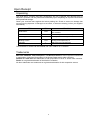
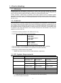
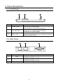
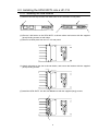
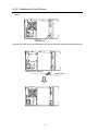
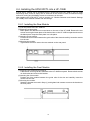
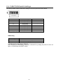
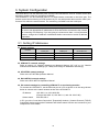
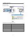
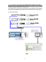
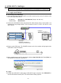
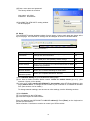

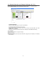
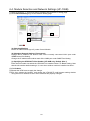

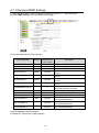
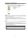
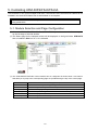

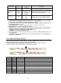
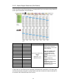
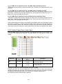
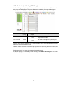
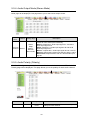
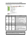
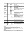
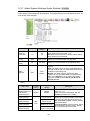

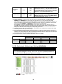
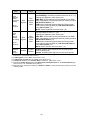
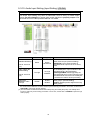
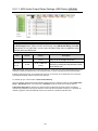
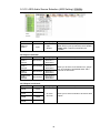
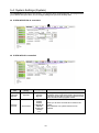
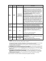
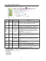

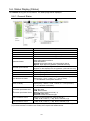

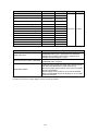
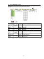
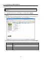
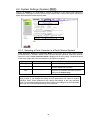

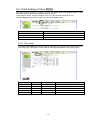
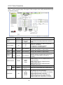
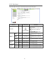

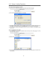

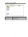
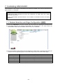
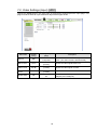
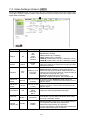

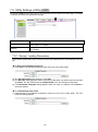
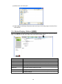
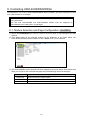
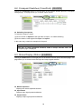
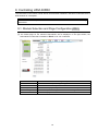
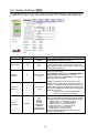
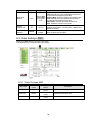
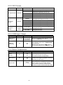
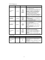
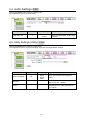
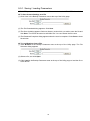
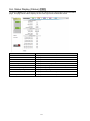
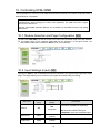
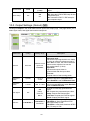
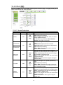
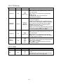
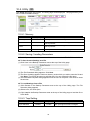
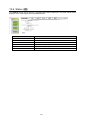
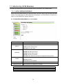
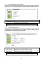
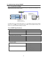
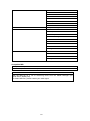
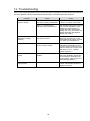
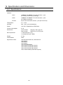
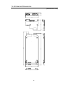
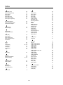

![取扱説明書[PDF:643.1KB]](http://vs1.manualzilla.com/store/data/006549213_2-64727dc84c6e8f0baf16030c4ecb9e3b-150x150.png)
![取扱説明書[PDF:556.1KB]](http://vs1.manualzilla.com/store/data/006556684_2-2cb9599dc72eb06fa8233d0b36239358-150x150.png)
![取扱説明書[PDF:957.5KB]](http://vs1.manualzilla.com/store/data/006607493_2-ccb6975feb1257d5d4cd7f1ae6269c5f-150x150.png)
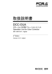
![取扱説明書[PDF:742.2KB]](http://vs1.manualzilla.com/store/data/006565526_3-f5702724d83f0c7d09b8852b97e3f732-150x150.png)
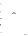
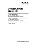

![取扱説明書[PDF:774.2KB]](http://vs1.manualzilla.com/store/data/006689674_2-aca49fe43eb7dd179675271ad81a417a-150x150.png)
![VTW Software Operation manual[PDF:17.4MB] - FOR](http://vs1.manualzilla.com/store/data/005725901_1-df2c6d7f9199f46fcf33ffa12e63545b-150x150.png)
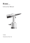
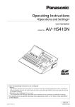
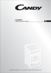


![UF-NETRU取扱説明書[PDF:1005.9KB]](http://vs1.manualzilla.com/store/data/006669382_2-bdb823d73fa79d5b41eeac91de47d491-150x150.png)