1
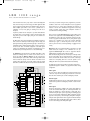
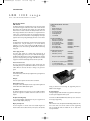
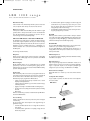
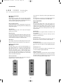
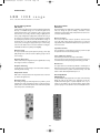
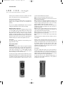
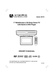
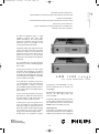
10/30/01
11:16 AM
Page 111
MICROPROCESSOR CONTROLLED •
USER FRIENDLY ALLOWING SPECIFIC FUNCTIONS TO BE EASILY AND
SPEEDILY PROGRAMMED •
SYSTEM EXPANSION MADE EASY AND ECONOMICAL DUE TO A LARGE
RANGE OF PLUG-IN MODULES •
48 VOLT EMERGENCY BATTERY POWER SUPPLY CONNECTOR •
SM30 SOUND
M A N AG E M E N T S YS T E M
PA databook.qxd
EEPROM USER’S DATA STORAGE •
The SM30 Sound Management System is a highly
sophisticated professional public address facility
controller, incorporating all the necessary interface
circuitry for the comprehensive range input and output
modules. The system has been designed to meet
commonly requested public address facilities.
A Call Station, including a high quality cardioid electret
condenser microphone, keypad buttons, and function
keys, allows the operator to route and transmit calls,
announcements, music, and alarm signals. A system of
priorities has been drawn up to cope with conflict
situations when a call is requested from two Call Stations
simultaneously.
Up to 36 loudspeaker zones can be selected all together,
with several zones combined, or individually by typing in
the zone number.
The SM30 system is intended for use with 2 separate
channels. One channel will amplify the “call” signal, and
the other one the “music” signal.This allows the music to
be transmitted without interruption, when a call is made
to other loudspeaker zones.To fulfil the need of amplified
power, more amplifiers can be installed.
LBB 1280 range
SM30 SOUND MANAGEMENT SYSTEM
Since the SM30 system is controlled by a microprocessor,
it is particularly flexible and the specific functions can
easily be programmed or changed by non-technical
personnel.All signal switching and routing procedures are
carried out by the software, so that wiring problems are
kept to a minimum.
In order to meet the various application needs, a range of
plug-in modules are available. The modules slide in and
out quickly, making the SM30 system simple and
inexpensive to assemble, to install, and to maintain.
The SM30 system has a pilot tone signal which can be
used for the surveillance of power amplifiers and their
output devices. A signal tone generator produces more
than 40 chime, attention, and alarm signals.These signals
can be programmed to precede a call or pre-recorded
message, or to be activated independently if required.
The SM30 system can be programmed by using the
programming keys and the LCD Display on the front
panel. The programming menus are presented in the
selected language.
Normally the Power Supply Module is connected to the
mains, but a 48 V DC emergency battery supply
connector is available.
A ‘Delayed Power On’ function is available to save battery
power by switching on amplifiers of the SQ45 range, only
when a Call is made. Since the user’s data is stored in an
EEPROM, a battery back-up facility is unnecessary.
System Operation
A public address sound distribution system comprises a
Control Centre, Call Stations and power amplifiers. The
amplifiers feed the loudspeakers located in geographical
Philips
Communication,
Security & Imaging
111
PA databook.qxd
10/30/01
11:16 AM
Page 112
SPECIFICATIONS
LBB 1280 range
SM30 SOUND MANAGEMENT SYSTEM
and/or functional zones where people must be reached with background
music, announcements, pre-recorded messages, and alarm signals.The SM30
system is designed to handle calls and music simultaneously by using a twochannel amplifier system. When a call is made to a particular zone or
combination of zones, music playing in remaining zones will not be
interrupted.
A system of priorities has been developed to cope with conflict situations.
For example, when a person attempts to make a call when another call is
being made by someone with a higher priority, the new call will not be
switched through.
The SM30 system can be fed by input signals from call stations, microphones,
music sources and a built-in pre-recorded messages card.The routing of an
input signal is started by pushing a Numeric Keypad key or Function Key on
a Call Station, closing a built-in microphone switch, or closing a contact of a
remote detector device. A maximum configuration of the SM30 system
contains up to 6 Call Stations and a maximum of 18 loudspeaker zones, or 3
call stations and up to 36 loudspeaker zones to be selected individually.
The Call Station is the primary input to the SM30 system.When a call is
activated, the following actions are carried out. The desired zones are
selected by pushing the Numeric Keypad keys. The microprocessor
detects which keys are pressed and, if another call is being handled at that
moment, it checks the priority of the new call. If the new call has a lower
priority, it will be ignored. If the new call has a higher priority, the original
caller will be overridden.After this, the microprocessor checks which chime
tone and/or pre-recorded message has been programmed to precede the
call. Music is muted in the selected loudspeaker zones, the programmed
announcement tone or message will be transmitted, the microphone is
switched on and the call is transmitted. Pre-programmed control relay
contacts can activate override relays in the loudspeaker enclosures to
secure full volume level during transmitting.
At the end of the call, the PRESS-TO-TALK key is released and the music
will return at its original volume-level. 4 Function Keys are provided on
the Call Station to route a call to a pre- programmed selection of zones.The
call can be programmed with functions such as priority, attention signal,
message, zone combination and control relay operation. Alternative
functions may be given to a Function Key, such as music source select,
volume up, down and mute, control relay switching or toggling and music
routing.
Microphone calls can be programmed with the same functions as a Call
Station. However, the routing to a zone combination has to be preprogrammed. Control Input ‘calls’ can also be programmed with the
available functions, depending on the specific input number.
With the Direct Routing function, the control inputs can directly activate
the zone relay modules of the pre-programmed music or alarm zones. For
instance, an external fire detection contact connected to the control input,
activates the corresponding alarm zone. If the fire expands to more
buildings, the alarm zone in question will be switched in automatically.
The SM30 system provides the user with more than 40 pre-programmed
signals. All these signals are available to be programmed in various routing
configurations.
Music
SQ45
Call
Pilot Tone
Line Output Module
AUX 1
AUX 2
AUX 3
Display/
keyboard
Music Input
Module
Zone Relay
Module 1
Chime Attention Alarm Signals -
Recorded
Message
Module
1
2
Call Station
Input
Module 1
Zone 1
Zone 6
Zone Relay
Module 2
Zone 7
Zone 12
MICROPROCESSOR
BOARD
Zone Relay
Module 3
Zone 13
Zone 18
1 Call Station
Input
2
Module 2
Control Relay
Module 1
1 Microphone
Input
2
Module
Mains
1
8
Control
Input
Module
1
Power Supply
Unit
48V DC
SM30 BASIC SYSTEM
1
8
1
8
1
8
Control
Input
Module
Control
Input
Module
Control
Input
Module
4
5
6
Zone 19
Zone Relay
Module 4
Zone 24
Zone 25
Zone Relay
Module 5
Zone 30
Zone 31
Zone Relay
Module 6
Zone 36
Mains
Control Relay
Module
2
Chime signals
The 1,2,3 or 4-tone chimes are available in two versions. In the first version,
a chime tone stops when the activating key is released.The second version
allows the chime to finish its cycle, even if the activating key is released.
Power Supply
Unit
48V DC
SM30 MODULE FRAME
112
Attention signals
Available signals are: fast whoop, two tone, crash signal, fire attention, etc.An
attention tone stops when the activating key is released or at the end of the
signal.
Alarm signals
All but two alarm signals are available in two versions: signal duration 60
seconds and continuous. Alarm signals are continuously transmitted, even
though the activating key is released. However, an alarm signal can be
terminated at any time by the operator by pressing the activating key again.
In order to conform with certain European military requirements, an alarm
signal can be interrupted by a call with a higher priority.After releasing the
call key, the alarm signal will return for the programmed duration. Examples
of available alarm signals are: DIN alarm, Muster alarm, 1 kHz tone, Morse
“F”, Fast or slow whoop, specific military alarm signals.
PA databook.qxd
10/30/01
11:16 AM
Page 113
SPECIFICATIONS
LBB 1280 range
SM30 SOUND MANAGEMENT SYSTEM
Basic Control Centre
LBB 1280/40
The Basic Control Centre and Module Frame houses the various printed
circuit boards and plug-in modules. Both units contain an Interconnection
Board with 12 slots in which the plug-in modules can be fitted. The Basic
Control Centre is delivered with the Line Output Module and the and
Power Supply Unit. All the other modules have to be supplemented in the
control centre or module frame in their own pre-designated locations.The
connections between the modules and the corresponding ‘input’ and ‘output’
equipment can be made by using standard plugs and screw connector blocks.
Cabinet
The Control Centre and module frame are delivered with 19-inch brackets,
and without cover ready for mounting in to a 19” rack. For table-top
applications a cover can be ordered under type No. LBB 1349/30. A set of
blanking plates can be ordered under type No. LBB 1292/00 to blank-off any
empty slots.
Power supply module
The power supply module has a standard mains supply plug plus an
emergency battery supply connector. In cases in which the mains supply is
unreliable, and the SM30 system is used for security, alarm and/or evacuation
purposes, an emergency battery power supply of 48 V DC can be used.This
supply can be switched in automatically whenever the mains power fails.
Interconnection board
All of the interconnections between the plug-in modules take place
automatically when they are installed. Each module has its own place in the
cabinets. Misuse in other slots will cause no damage to any part of the
system.
The Basic Control Centre LBB 1280/40
comprises:
• Cabinet
• Display and Keyboard
• Microprocessor Board
• Interconnection Board
• Power Supply Module
• Line Output Module
• User’s Manual
The optional modules are:
- Microphone Input Module
- Call Station Input Module
- Control Input Module
- Recorded Message Module
- Music Input Module
- Zone Relay Module
- Control Relay Module
LBB 1282/00
LBB 1283/00
LBB 1284/00
LBB 1285/00
LBB 1286/10
LBB 1287/00 - LBB 1287/10
LBB 1288/00
The optional accessories are:
- Call Station (18 zones)
- Call Station (36 zones)
LBB 9568/30
LBB 9568/36
-
-
Microphones (with call switch)
LBB 9517/10
LBB 9520/10
LBB 9094/10
LBB 9090/00
Module frame for extended systems LBB 1291/40
Set of slot blanking plates
LBB 1292/00
Top cover plate for table-top use LBB 1349/30
Line output module
This module interfaces all the audio input signals and the system signal tones
to the outputs.
Outputs
There are separate outputs for the ‘music’ and the ‘call’ channel.
Output Volume Level
Two separate controls allow adjustment of the output volume signal level of
both the Alarm and the Chime/attention signals.
Surveillance
The built-in 20 kHz pilot tone signal can be used for amplifier surveillance
purposes. The signal can be switched on/off and the volume level can be
adjusted.
Amplifier Switching Relay
In a one-channel amplifier configuration, this relay can be programmed to
activate the SQ45 amplifier priority relay.
Display and keyboard
The User Programme is a shorter version of the Installer Program. It is
intended to allow the user, without the help of an expert, to alter priorities,
113
routing, etc. whenever his needs change. The programming menus are
available in various languages.
Programming Keys
10 Programming Keys enable the installer to programme the SM30 system
to suit the system configuration and the specific
needs of the user. Illuminated LEDs indicate which keys can be used at the
current stage of programming.
Display
In the normal ‘run’ mode, the alphanumeric LCD Display indicates the name
of the current music source and the volume level. In the programming
mode, the display will enable the installer and user to obtain all the
necessary information.
PA databook.qxd
10/30/01
11:16 AM
Page 114
SPECIFICATIONS
LBB 1280 range
SM30 SOUND MANAGEMENT SYSTEM
Music Function Keys
In the normal ‘run’ mode, 4 Function Keys allow the operator to select music
source, to adjust the volume level up or down, and to mute the music.
•
Microprocessor board
A microprocessor PCB controls the SM30 system. Also included is a signal
generator, which is already encoded with more than 40 chime/attention
tones and alarm signals.They can be programmed to precede a call, a prerecorded message, or to be activated independently.
•
Call Station LBB 9568/30 or Call Station LBB 9568/36
The Call Station of the SM30 system is a desktop unit which presents the
operator with a logical, comprehensive, and easy to use method of routing
and transmitting calls, alarms, announcements, and music. As an option, the
Call Station can also be semi-flush mounted. Up to 6 Call Stations, or 3
extended call stations can be connected in the maximum configuration of
the SM30 system.
The wide range of features includes:
Microphone
Phantom powered cardioid electret condenser microphone of high quality
with a built-in bass roll filter giving a clear voice reproduction, even in difficult
acoustic environments.
Numeric Keypad
Allowing individual selection of up to 18 loudspeaker zones in a standard
system, and up to 36 zones in an extended system, by typing in the zone
number. Each zone has its own Zone Selection Indicator LED. A Recall Key
repeats the last keypad selection.
Function Keys
With a Function Key a call can be routed to a pre-programmed selection of
zones, saving a great amount of time when an operator has to frequently call
the same zones, or when an “ALL CALL” must be made in emergencies.
Each function key may be programmed for different tasks as:
• routing a low priority call, preceded by an attention tone, to several
frequently used loudspeaker zones.
• routing an alarm tone, followed by a pre-recorded evacuation message,
to all loudspeaker zones
• toggling a control relay on and off which switches a warning lamp, etc.
• selecting a music source, turning the music volume up/down, and muting
the music.
• Music routing
Whenever a function key is pressed, the relevant Function Key LED and the
relevant zone LEDs illuminate.
Press-to-talk Key
Activates a call after the zones have been preselected by means of a Keypad
or Function Key.
The way in which a call is executed depends on the programmed type of
signal and/or message:
• A normal call without attention tone or message will reset when the
key is released.
• A call with attention signal and/or non-repeating message will reset
when the key is released.
114
A call with attention signal and repeating pre-recorded message will
continue after the key is released. If you press the key for a second
time, the attention signal will stop immediately and a pre-recorded
message will stop at the end of the message.
A call with alarm signal will continue after release of the key and can be
stopped by pressing the key a second time.
Busy LED
LEDs are provided to advise the operator whether a call may be activated
or the call is accepted.The red ‘Busy’ LED flashing means that another call is
in progress. The red ‘Busy’ LED lighting up continuously indicates that the
call has been blocked by another call with a higher priority.
Wait/Talk LED
The green ‘Wait’ LED flashing indicates that the call is accepted, and the
attention tone or pre-recorded message is being transmitted.
The green ‘Talk’ LED lights up continuously when the attention tone or
message finishes and the microprocessor switches on the microphone to
enable speech broadcast
LED Intensity Preset
To compensate for various local lighting conditions, the illumination intensity
of the LEDs can be adjusted.
Built-in Compressor
Helps to keep the signal output level of the Call Station constant, even in
situations where the operator’s speech volume level changes radically. The
degree of compression depends on the microphone preamplifier gain
setting. It can be preset over a range of 30 dB from 84 to 114 dB (SPL).
Balanced Line Level Output
Allows Call Stations to be located up to 1000 metres from the Control
Centre.
Loudspeaker Zone Template
A paper template is provided, onto which the names of the loudspeaker
zones can be written.
LBB 9568/30
LBB 9568/36
PA databook.qxd
10/30/01
11:16 AM
Page 115
SPECIFICATIONS
LBB 1280 range
SM30 SOUND MANAGEMENT SYSTEM
Microphone Input Module
LBB 1282/00
Each Microphone Input Module allows two high quality hypercardioid
electret or dynamic microphones to be connected to the Control Centre. In
total up to 3 Microphone Input Modules or Call Station Input Modules may
be used.A microphone with priority contact must be used.
Remote Switching Function
The SM30 system uses the remote switching facility of microphones. The
built-in switch can activate a call, including all the functions available (priority,
routing, attention signals, etc.).
Input Selection
Selection of the Microphone Input or the Line Input (line level signal) is
possible by means of a switch.
Bass-Cut Facility
In noisy environments, the operator often has to speak very close to the
microphone which exaggerates the microphone’s bass frequencies. A basscut facility is available to reduce the bass, helping the call to be heard clearly.
Selection of Bass Cut or Flat Response is possible with a switch.
Gain Control
As the strength of each person’s voice differs, input gain controls are used for
‘lining up’ the microphones volume level with the rest of the signal sources.
Call Station Input Module
LBB 1283/00
This module allows the choice of either two standard Call Stations or a
single extended call station to be connected to the Control Centre. The
SM30 system will accept up to 3 Call Station Input Modules and/or
Microphone Input Modules in total. A standard Call Station may be
connected via a cable with a length of up to 1000 metres, which contains 2
screened wires (audio signals and powering) and 2 unscreened wires
(control and data signals). An extended call station can be connected using
either two of the cables mentioned above.
Volume Level Controls
The potentiometers are input volume level controls used for “lining-up” the
Call Station microphone volume level with the rest
115
of the signal sources (microphones, attention signals, background music
players, etc.).
The controls can be set to provide a clear, comfortable listening level for
speech signals, which are balanced with the other amplified signals.
Control Input Module
LBB 1284/00
Each Control Input Module allows 8 remote make contacts to be
connected to the Control Centre. Up to 3 Control Input Modules can be
installed in the basic system, allowing a total of 24 contacts to be used. In
extended systems an additional 3 Control Input Modules can be installed.
When a remote contact closes, the SM30 system starts a series of preprogrammed actions.
Control Inputs
Each control input can be programmed similar to the functions of a call
from a Call Station.
In addition, direct routing control of the music or call relays on the Zone
Relay Card is possible via the inputs.
Control Inputs 1 to 4
Apart from the normal call activation, these inputs may be given an
alternative function to allow remote activation of the Music Functions.
Control Inputs 5 to 8
These inputs may be programmed to activate control relays, whose contacts
can be used to start remote equipment, to activate signalling, warning lamps,
etc.
Control Inputs 1 to 8
These inputs can be programmed to distribute an external audio source
connected to a Microphone Input Module LBB 1282.
Wiring Control Inputs
A plug-in, 16 terminal screw connector block is mounted for wiring the
remote contacts. If the Control Centre has to be removed for some reason,
the block has simply to be unplugged and the wires remain intact. This
avoids the tedious and risky business of rewiring the blocks.
PA databook.qxd
10/30/01
11:16 AM
Page 116
SPECIFICATIONS
LBB 1280 range
SM30 SOUND MANAGEMENT SYSTEM
Recorded Message Module
LBB 1285/00
Music Input Module
LBB 1286/10
A unique feature of the SM30 system is its Recorded Message Module, which
allows up to 4 individual messages to be recorded and played back as
desired.The SM30 system can be programmed so that a message is played
back either alone, or preceding a call. The recording is digitally stored in
memory chips, ensuring that the quality will not deteriorate for as long as
the message is in memory. If the power of the Control Centre is switched
off, a back-up battery mounted onto the module will enable the message to
remain intact for up to 30 days. The maximum total recording time is 65
seconds, and up to 4 messages of varying duration may be recorded, as long
as the sum of the duration’s does not exceed the maximum recording time.
A bandwidth of 6 kHz ensures optimal speech intelligibility.
An important feature of the SM30 system is the ability to play uninterrupted
music, even though the system is handling a call routed to other
loudspeaker zones.This module enables 3 independent music sources to be
connected to the Control Centre.
Microphone Input
The 5-pole 180° DIN socket provides phantom powering, so that a high
quality microphone of a condenser as well as a dynamic type may be used to
record a message.
Automatic Gain Control
A limiter ensures that, even though the microphone signal fluctuates severely,
the message is recorded at a constant level.
Headphone Monitoring
A socket allows the recorded messages to be monitored with a headphone,
both during and after recording.
Output Volume Control
With a volume control potentiometer the output volume level can be “linedup” with the other signal sources.
Message Recording
Re-recording of messages is possible. Safety features are provided to prevent
accidental erasure of the message. Remote location recording of a message is
possible, as the record and monitor functions of the module are independent
of the microprocessor of the SM30 system.
116
Music Source Inputs
Three sets of double cinch sockets are provided to connect the music
sources. The double sockets allow stereo signal sources to be connected,
using standard double cinch/cinch HI-FI cables.The stereo signal is mixed to
mono in the module.
Input Volume Controls
Three potentiometers corresponding to the inputs are provided to adjust
the input volume level of each source independently.
Treble and Bass Tone Controls
Treble and bass potentiometers allow output control facilities.
They increase the level of the relevant treble or bass frequency range by up
to 10 dB and decrease the frequency range volume level by up to 10 dB.
Music Control
The output volume level of the Music Input Module is controlled by the 4
Music Function keys mounted on the front of the Control Centre. Remote
control of these functions is possible via the Functions Keys on the Call
Stations or via the Control Input Module inputs 1 to 4.
Zone Relay Module
LBB 1287/00,/10
The SQ45 Amplifier output signals return to the inputs of the Zone Relay
Module. The relays on this module can be programmed to route the
amplified call and music signals to 6 separate loudspeaker zones. Up to 3
modules can be installed in the basic Control Centre, giving the SM30
system the capacity to route calls and/or music to 18 loudspeaker zones. In
PA databook.qxd
10/30/01
11:16 AM
Page 117
SPECIFICATIONS
LBB 1280 range
SM30 SOUND MANAGEMENT SYSTEM
extended systems an additional 3 modules can be installed in the module
frame, to route calls and/or music to an extra 18 loudspeaker zones.
Coupling Zone Relays Modules
The inputs of the modules may be linked together to the outputs of the
amplifier, so that one amplifier can feed up to 36 loudspeaker zones
(maximum).
Two versions are available. The ZRM LBB 1287/00 is made for single pole
switching and the LBB 1287/10 is made for double pole switching.
Multiple Amplifier Configuration
In an SM30 system with a large number of loudspeakers, it may be necessary
to use extra amplifiers because the high amplifier power required exceeds
the power available. Each amplifier can be used to feed one Zone Relay
Module which covers 6 specific zones. However, the module provides the
possibility of connecting two amplifiers, so that each amplifier feeds fewer
loudspeaker zones. One amplifier will feed the outputs 1 to 4 and the other
will feed the outputs 5 and 6. In this case, when 3 Zone Relay Modules are
installed for example, up to 6 ‘call’ and 6 ‘music’ amplifiers can be used.
Termination’s
The module is fitted with 2 ‘Mate-N-Lok’ connectors. All wiring is to the
plugs provided with the module.
Control Relay Module
LBB 1288/00
The Control Relay Module contains 12 relays to be programmed separately.
It provides the SM30 system with a set of make and/or break contacts for
use with volume override applications, starting remote equipment, such as
cassette players, message loggers, etc., to activate signalling and warning
lamps, to release fire door relays, etc. Relays 1 to 8 have both make and
break contacts. Relays 9 to 12 have make contacts only.
In extended systems, using the SM30 Module Frame LBB 1291/40, up to two
additional Control Relay Modules can be installed, providing a system with up
to a maximum of 36 output contacts. If relays (25 - 36) are needed, a minor
electrical and mechanical modification is required, if relays (13 - 24) are
117
needed an electrical modification only is required.
Relay 1 is reserved for the indication of microprocessor errors.
Relay 2 is reserved for the indication of all other internal errors in the
present Modules and Call Stations.
Relay 3 is dedicated to the Delayed Power ON function, but may be used
for other functions. The programmable Delayed Power On function is
intended for battery operated systems where, in order to save battery
power, the amplifiers are switched on only when a call is made.
Relay 4 is dedicated to start an external audio source, if that audio source
is distributed via a Control Input Module and the audio connected to a
Microphone Input Module.
Relays 3 to 12 can be activated by different sources and may be used for a
number of functions.Activation from a Call Station is done whenever a call
is made, using the Keypad keys or the Function Keys.
Relays 13 to 24 for use in extended systems using the SM30 Module
Frame. Programmable features are as listed above.
Relays 25 to 36 for use in extended systems using the SM30 Module
Frame.
Programmable features are as listed above. If used a maximum of 30 zones
only is applicable.
Activation can also be achieved by closing an input contact of the control
input relays 5 to 8.A typical application of the Control Relay Module is the
activation of the loudspeaker volume control override relays, mounted in
the loudspeaker enclosures. These relays override the volume control
setting of the loudspeakers to get the full volume level when a Call is
transmitted. For this application, the control relays are ‘locked’ to the preprogrammed corresponding zone relays.
Termination’s
The module is supplied with 2 plug-in screw connector blocks with 16
terminals. The great advance of the connector block is that, if for some
reason the Control Centre has to be removed, the block has simply to be
unplugged and the wires remain intact. This avoids the tedious and risky
business of rewiring the blocks in their original configuration.
In a basic frame their is room for a single Control Relay Module. In an
extended system, using an additional module frame, room is provided for
an additional one or two modules.
PA databook.qxd
10/30/01
11:16 AM
Page 118
SPECIFICATIONS
LBB 1280 range
SM30 SOUND MANAGEMENT SYSTEM
for power on/off switching
mute by on/off switch
GENERAL
The specification relates to a Control Centre with corresponding modules.
Pilot tone 20 kHz sinus asymmetrical
volume preset at least : 0.05-1 V
mute by on/off switch : > 80 dB
MICROPROCESSOR HARDWARE
EEPROM data storage time : >10 years
RECORDED MESSAGE MODULE
data retention
audio bandwidth
max. total recording time
max. number of messages
microphone phantom power
supply voltage
:
:
:
:
MAINS SUPPLY
voltage setting at delivery
mains voltage selection range
maximum voltage deviation
for all selected ranges
however at 230 V mains
mains frequency
power consumption
at mains voltage
mains fuse
mains transformer
temperature switch
self restoring type
>30 days
320 - 6000 Hz
65 seconds
4
: 12 V DC
AUDIO OUTPUTS
Music input to music output
gain:
control range
mute
input level
output level symmetrical:
nominal
maximum
amplifier output distortion
THD at nominal level
THD at max. output
amplifier S/N output
at nominal level
Call Station or Microphone
input to call output
output level symmetrical
nominal
maximum
Microphone Input Module
input level
frequency response
signal-to-noise ratio
Call Station
input level
frequency response
signal-to-noise ratio
amplifier output distortion
THD at nominal level
THD at max. output
: > 60 dB (2 dB steps)
: > 80 dB
: >150 mV
: 220-230 V
: 110 V, 127 V, 220-230 V or 240 V
: +10/-10%
: + 6/-10%
: 50-60 Hz
: < 90 VA
: T2.5 A
: +125 °C
EMERGENCY SUPPLY
The unit can be supplied from an external DC voltage
V DC nominal : 48 V @ current: <1.2 A
V DC minimum : 42 V @ current: <1.2 A
V DC maximum : 58 V @ current: <1.2 A
fuse in 48 V DC line on PCB located in housing
polarity protection against reverse connection
: 0 dBV
: +12 dBV
: 0.1%
: 0.3%
: > 80 dB (flat)
MECHANICAL DATA
Dimensions (H x W x D)
: 0 dBV
: +12 dBV
: >1.5 mV
: 50-15000 Hz (+/- 2 dB)
: 68 dB (flat)
weight LBB 1280
: 133 x 440 x 360mm ( 3HE, 19”
rack height)
H = 133 mm (3U)
W = 440 mm (incl. 19” brackets
W = 483 mm)
D = 360 mm incl. handgrips.
Build-in depth = 310 mm (19” rack)
: 8.8 kg (unpacked)
ENVIRONMENTAL REQUIREMENTS
Rated range of use
ambient temperature : -10 to +45 °C
relative humidity : 15 - 90%
: > 84 dB (SPL)
: 440-12500 Hz (- 3 dB)
: 58 dB (flat)
: 0.1%
: 0.3%
Climatic conditions during transporting handling and storage
according to : UN-D 1639/01
temperature : -40 to +70 °C
relative humidity : 5 - 95%
Music and call Output Impedance
at 1 kHz : < 50 Ω
Click suppression in combination for any module
for audio switching : > 60 dB
9498 974 03314 01-08
: > 30 dB
: > 80 dB
© 2001 Philips Electronics N.V.
118