1
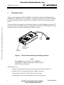
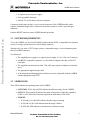
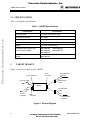
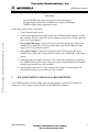
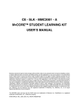
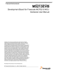
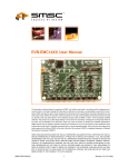
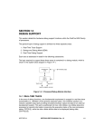
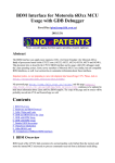
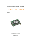
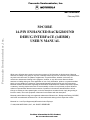
Freescale Semiconductor, Inc. MMC14EBDIUM/D Freescale Semiconductor, Inc... February 2000 M•CORE 14-PIN ENHANCED BACKGROUND DEBUG INTERFACE (14EBDI) USER’S MANUAL While every effort has been made to ensure the accuracy of all information in this document, Motorola assumes no liability to any party for any loss or damage caused by errors or omissions or by statements of any kind in this document, its updates, supplements, or special editions, whether such errors are omissions or statements resulting from negligence, accident, or any other cause. Motorola further assumes no liability arising out of the application or use of any information, product, or system described herein; nor any liability for incidental or consequential damages arising from the use of this document. Motorola disclaims all warranties regarding the information contained herein, whether expressed, implied, or statutory, including implied warranties of merchantability or fitness for a particular purpose. Motorola makes no representation that the interconnection of products in the manner described herein will not infringe on existing or future patent rights, nor do the descriptions contained herein imply the granting or license to make, use or sell equipment constructed in accordance with this description. Motorola and the Motorola logo are registered trademarks of Motorola Inc.; Background Debug, M•CORE, and OnCE are trademarks of Motorola Inc. All other trademarks belong to their respective owners. Motorola Inc. is an Equal Opportunity/Affirmative Action Employer. 1998, 2000 MOTOROLA, INC.; ALL RIGHTS RESERVED For More Information On This Product, Go to: www.freescale.com Freescale Semiconductor, Inc. 14EBDI User’s Manual 1 INTRODUCTION Freescale Semiconductor, Inc... Figure 1 shows the Motorola MMC14EBDI02 14-Pin Enhanced Background Debug Interface (14EBDI). The 14EBDI lets you use an IBM PC-compatible computer or a Sun Solaris computer to manage debugging and other embedded code development tasks with an appropriate target board. The target board does not require on-board debug firmware, nor does debugging consume MCU resources. Instead, the 14EBDI exercises the target MCU and performs all the debugger functions through the OnCE or Background Debug Mode (BDM) connector. Target Cable DB9 Serial Port Connector Power Connector Figure 1. 14-Pin Enhanced Background Debug Interface NOTE The 14EBDI replaces Motorola’s earlier EBDI (the MMCEBDI01), adding compatibility for MMC2080 and MMC3401 microcontrollers. 14EBDI features are: • Support for M•CORE™ target systems that have OnCE™ debug connectors. • Support for CPU32 target systems that have BDM connectors. • Target interface cables for CPU32 and OnCE connections. • Operating power from a separate supply or from the target system. 2 For More Information On This Product, Go to: www.freescale.com MMC14EBDIUM/D Freescale Semiconductor, Inc. 14EBDI User’s Manual • A separate universal power supply. • User-upgradable firmware. • An EIA-232 serial cable to the host computer. Connection to the target system is via a recessed connector of the 14EBDI module, and a separate, detachable target cable. Connection to the host system is via the 9-pin serial port connector. Freescale Semiconductor, Inc... Push the RESET button to restart 14EBDI internal operations. 1.1 SYSTEM REQUIREMENTS To use the 14EBDI, you need an M•CORE evaluation board (EVB), a comparable development system, or a target system that uses a OnCE debug connector. Alternatively, you need a CPU32 target system, a comparable target, or a development system that uses a BDM connector. You also need: • The supplied power supply or a separate power supply: 4.5 to 8 volts, at 0.2 amperes. • An IBM PC-compatible computer, or a Sun Solaris computer, that has an EIA-232 serial port. • The supplied communications cable. (The cable may require an adapter to match the host.) • The appropriate supplied target cable. • A development and debugging host software tool suite compatible with the 14EBDI and the appropriate target CPU. 1.2 14EBDI LEDS Three LEDs indicate the operating status of the 14EBDI: • LOW PWR: If ON, this red LED indicates insufficient voltage for the 14EBDI. • STATUS: This green LED indicates the mode of operation or indicates a problem. (Table 4, at the end of this document explains the indications of this LED. • TARGET: If ON and green, this LED indicates that the target is running. If ON and red, this LED indicates that the target is halted. If OFF, this LED indicates a disconnected or unknown target. MMC14EBDIUM/D For More Information On This Product, Go to: www.freescale.com 3 Freescale Semiconductor, Inc. 14EBDI User’s Manual 1.3 SPECIFICATIONS Table 1 lists interface specifications. Table 1. 14EBDI Specifications Freescale Semiconductor, Inc... Characteristic 2 Specification Operating power + 4.5 volts–8 volts @ 0.2 amps Operating temperature 0°C to 40°C Storage temperature 0°C to 85°C Shell dimensions 5.0 x 2.75 x 1.25 inches (127 x 69.85 x 31.75 mm) Weight 3.6 ounces (102.06 grams) Compatible with controller and memory boards (CMBs) MMCCMB1200, MMCCMB2102, MMCCMB4301 MMCCMB2080, MMCCMB2103, Compatible with evaluation boards (EVBs) MMCEVB1200, MMCEVB2103 MMCEVB2080, TARGET HOOKUP Figure 2 shows how to hook up your 14EBDI. Power connector 16-pin connector To power supply To target OnCE connector OnCE target cable 14EBDI CPU32 target cable To host computer DB9 connector To target BDM connector Figure 2. Hookup Diagram 4 For More Information On This Product, Go to: www.freescale.com MMC14EBDIUM/D Freescale Semiconductor, Inc. 14EBDI User’s Manual CAUTION Turn off 14EBDI and target system power when connecting or disconnecting the target cable. Sudden power surges could damage 14EBDI or target system integrated circuits. Follow these steps to make connections: Freescale Semiconductor, Inc... 1. Turn off target-system power. 2. Connect the communications cable between the 14EBDI D-shell connector and the host computer EIA-232 serial port. (If the computer serial port is a 25-pin connector, use a 9-to-25-pin adapter.) 3. For an M•CORE target: Connect the 16-pin end of the OnCE target cable to the 14EBDI. Then connect the 14-pin end of the cable to the OnCE connector of the target system or development system. 4. For a CPU32 target: Connect the 16-pin end of the CPU32 target cable to the 14EBDI. Then connect the 10-pin end of the cable to the 10-pin header of the target system 5. If the target does not supply at least 4.5 volts, connect the external power supply to the 14EBDI and the power outlet. (This may require reconfiguring the power supply to match your national electrical standards.) 6. Turn on target-system power. This completes the hookup. You may begin code development activity per your software's user’s manual. 3 PIN ASSIGNMENTS AND SIGNAL DESCRIPTIONS Your 14EBDI connects to an M•CORE target system through a 14-pin OnCE connector. It connects to a CPU32 target system through a 10-pin BDM port connector. MMC14EBDIUM/D For More Information On This Product, Go to: www.freescale.com 5 Freescale Semiconductor, Inc. 14EBDI User’s Manual 3.1 ONCE CONNECTOR Figure 4 shows the pin assignments for the OnCE debug port connector of an M•CORE target system. (The marking on the connector identifies Pin 1.) Table 2 lists the signal descriptions for such a connector and the 14EBDI OnCE target cable. • TDO 3 • TCLK 5 • GPI 7 • RESET* 9 • VDD 11 • GPO 13 • Freescale Semiconductor, Inc... TDI 1 • • • 2 GND 4 GND 6 GND 8 KEY (removed pin) • 10 TMS • 12 DBEV* • 14 TRST* Figure 4. OnCE Connector Pin Assignments Table 2. 14EBDI OnCE Connector Signal Descriptions 6 Pin Name Function 1 TDI TEST DATA IN — Serial data input signal for OnCE debug logic. 2,4,6 GND GROUND — Power and signal return. 3 TDO TEST DATA OUT — Serial data output signal for OnCE debug logic. 5 TCLK TEST SERIAL CLOCK — Clock input signal for OnCE debug logic. 7 GPI 9 RESET* 10 TMS TEST MODE SELECT — Input pin used to sequence the OnCE controller state machine. 11 VDD Power supply — Interface operating power (not used for lowvoltage or separate power hookups). 12 DBEV* 13 GPO 14 TRST* GENERAL PURPOSE INPUT — General data input to the target. RESET — Active-low, bidirectional signal to reset the system. DEBUG EVENT — Active-low, bidirectional signal to force the target into debug mode. The target processor can also pull this signal low to indicate that it has entered debug mode. GENERAL PURPOSE OUT — General data output from the target. TEST RESET — Active-low signal to reset the OnCE state machine and debugging logic. For More Information On This Product, Go to: www.freescale.com MMC14EBDIUM/D Freescale Semiconductor, Inc. 14EBDI User’s Manual 3.2 BDM CONNNECTOR Freescale Semiconductor, Inc... Figure 5 shows the pin assignments for the BDM connector of a CPU32 target system. (The marking on the connector identifies pin 1.) Table 3 lists the signal descriptions for such a connector and the 14EBDI 10-pin CPU32 target cable. DS* 1 GND 3 GND 5 RESET* 7 VDD 9 • • • • • • 2 • 4 • 6 • 8 • 10 BERR* BKPT* FREEZE DSI DSO Figure 5. BDM Connector Pin Assignments Table 3. BDM Connector Signal Descriptions Pin Name Function 1 DS* DATA STROBE — Active-low output signal. During a read cycle, indicates that an external device should place valid data on the data bus. During a write cycle, indicates that valid data is on the data bus. 2 BERR* 3, 5 GND 4 BKPT* DSCLK BUS ERROR — Active-low input signal of an invalid bus operation attempt. GROUND — Power and signal return. BREAKPOINT — Active-low input signal that signals a hardware breakpoint to the CPU; DEVELOPMENT SERIAL CLOCK — Clock input signal for background debug mode. 6 FREEZE FREEZE — Signal that the CPU has acknowledged a breakpoint. 7 RESET* RESET — Active-low, bi-directional signal to reset the system. 8 DSI DEVELOPMENT SERIAL IN — Serial data input signal for background debug mode; INSTRUCTION FETCH for CPU32-based MCUs. 9 VDD VOLTAGE DRAIN — DRAIN — Interface operating power (not used for low-voltage or separate-power hookups). 10 DSO DEVELOPMENT SERIAL OUT — Serial data output signal for background debug mode.; INSTRUCTION PIPE for CPU32-based MCUs. MMC14EBDIUM/D For More Information On This Product, Go to: www.freescale.com 7 Freescale Semiconductor, Inc. 14EBDI User’s Manual 4 SELFTEST AND LED INFORMATION When you apply power to the 14EBDI, it runs a built-in selftest. The LEDs indicate the condition of the 14EBDI. To run the 14EBDI selftest: 1. Make sure that the 14EBDI is not connected to a target, and that it is not connected to the host computer. Freescale Semiconductor, Inc... 2. Apply power to the 14EBDI 3. Examine the LEDs. If the 14EBDI is operating properly, The low-power LED is off, The status LED blinks every one or two seconds, and The target LED is off. As you use the 14EBDI, the LEDs convey other status information, which Table 4 explains. Table 4. LED Status Indications LED State Meaning Corrective Action If connected to a PC host computer: the 14EBDI is idle, ready for connection to the debugger. None This is a normal condition. If not connected to a host computer: corrupted firmware. Contact Motorola customer service. Status LED stays lit without blinking. If connected to a Solaris host computer: the 14EBDI is idle, ready for connection to the debugger. None This is a normal condition. Status LED blinks quickly and erratically. The 14EBDI is receiving data from the host computer. None This is a normal condition. Status LED goes off for extended periods of time. The 14EBDI is executing a command. None This is a normal condition. Status LED blinks, but lowpower LED is on. Marginal power. Verify the voltage and current of power supplied to the 14EBDI. Status LED off, low-power LED on. Insufficient power. Supply power in the range 4.5-to-8 volts, at 0.2 amperes. Status LED blinks every one or two seconds. 8 For More Information On This Product, Go to: www.freescale.com MMC14EBDIUM/D Freescale Semiconductor, Inc. 14EBDI User’s Manual Table 4. LED Status Indications (continued) LED State Freescale Semiconductor, Inc... All LEDs off Status LED blinks several times quickly, pauses, then repeats this pattern. MMC14EBDIUM/D Meaning Corrective Action Insufficient power. Verify that power is getting to the 14EBDI. External power has wrong polarity. Correct the polarity of the external power. (Pin is +, sleeve is -.) External voltage is too high; internal regulator shut down. Supply power in the range 4.5-to-8 volts. Internal 14EBDI hardware failure. Contact Motorola customer service. For More Information On This Product, Go to: www.freescale.com 9 Freescale Semiconductor, Inc. Freescale Semiconductor, Inc... 14EBDI User’s Manual 10 For More Information On This Product, Go to: www.freescale.com MMC14EBDIUM/D Mouser Electronics Authorized Distributor Click to View Pricing, Inventory, Delivery & Lifecycle Information: Freescale Semiconductor: MMC14EBDI02