1
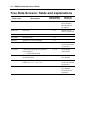
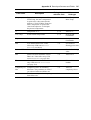
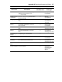
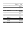
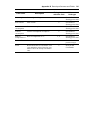
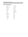
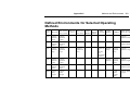
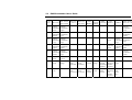
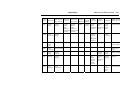
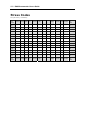
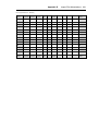
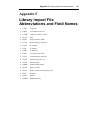
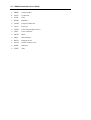
Appendix A Glossary of Field Abbreviations 591
Appendix A
Glossary of Field Abbreviations
Field
Definition
ComplLa
weighing (complexity) factor in reliability
allocation for La
FIT
failure rate in units of 10-9
FR
failure rate
L
(λ) failure rate (measure of reliability)
La
allocated failure rate
Lf
field failure rate (imported from FRACAS)
Lm
manually entered failure rate
Lp
predicted (calculated) failure rate
Ma
maintenance action
Mct
maintenance corrective time
MMH
mean maintenance man-hours
MTBCF
mean time between critical failures
MTBF
mean time between failures
MTTR
mean time to repair
NPRD
non-electronic part reliability data
PD
power dissipation
PTB
product tree building
R(t)
reliability as a function of time
592 RAM Commander User’s Guide
Field
Definition
RBD
reliability block diagram
RG
reliability growth
RP
reliability prediction
RP component
data
RP-related data influenced by the reliability
prediction model (“Processor”)
RTF
RAM Commander file format, used for importing
data from ASCII files
S
ambiguity factor (average number of iterations
required to correct a fault)
TAT
turn-around time
VSR
voltage stress ratio
Wm
weighing (complexity) factor for maintainability
allocation
Xi
probability of fault isolation to Ni replaceable
items
Appendix B Data Input Screens and Fields 593
Appendix B
Tree Data Input Screens and
Fields
The numbers in the column “Dialog boxes with this field” on the next page refer to the table
below:
Dialog box name
Number
Tree Level Item Parameters
1
Tree General
2
Tree Operating (reliability)
3
Tree Nonoperating (reliability)
4
Tree Maintainability
5
Tree Miscellaneous
6
594 RAM Commander User’s Guide
Tree Data Screens: fields and explanations
Field name
Description
Dialog boxes
with this field
Values or
field type
Family
Item family
2–4
--ELECTRONIC
MECHANICAL
EL-MECH.
Item code
Item code
2–4
See list of item
codes on page 600
Ref. Des.
Reference Designator
1–6
Part name
Item part name
1–4
Quantity
Quantity in current assembly
2–5
Environment
Item environment
1, 3-4
See list of
environment codes
on page 603
Cur. ENV
Current environment (set to parent’s
environment if
––– in Environment field
1, 3-4
Set by RAM
Commander
Method of Lp
If user defined, you must fill in
the Method field
3–4
Default
User defined
Method
Required if Method of Lp or Method
of Mct are user defined
3–4
See list of
prediction methods
on page 601
(No prompt)
Source for failure rate
3–4
Calculated
User defined
From FRACAS
Allocated
Appendix B Data Input Screens and Fields 595
Field name
Description
Dialog boxes
with this field
Values or
field type
(No prompt)
Type of ambient temperature. If
Fixed Temp, the item’s temperature
is equal to the value entered in the
adjacent °C field. If Delta Temp, the
item’s temperature is equal to the
value in the adjacent °C field plus
the parent’s temperature.
1, 3–4
Fixed Temp
Delta Temp
o
Temperature in oC
1, 3–4
Value in oC
Cur. Temp.
Actual current temperature
1, 3, 4
Set by RAM
Commander
FRp
Predicted (calculated) failure rate
1, 3–4
Set by RAM
Commander
FRu
User defined failure rate. Takes
effect only if FR source is user
defined (see above)
3–4
User defined
floating point value
Source of FRu
Source of user defined failure rate
3–4
User defined string
value
FRf
Failure rate from field data or from
FRACAS. Takes effect only if FR
source is FRACAS (see page 594)
3–4
Value of Lf
FRa
Allocated failure rate. Takes effect
only if FR source is Allocated
(see page 594)
1, 3–4
Value of allocated
lambda
Complexity for Complexity factor for reliability
FRa
allocation. This parameter is valid if
you selected Allocated failure rate
3–4
Value of
complexity factor
Field factor
3–4
C
Field factor multiplier for computing
item failure rate
596 RAM Commander User’s Guide
Field name
Description
Dialog boxes
with this field
Values or
field type
Duty cycle
Duty cycle multiplier for computing
item failure rate
3
Mult. factor
Multiplicative factor multiplier for
computing item failure rate
3–4
Add. factor
Additive factor multiplier for
computing item failure rate
3–4
Item Failure
Computed failure rate value of
current item
3–4
Set by RAM
Commander
Status Check
Check status
3–5
Set by RAM
Commander
--- = no status
Err = Error
Warn = Warning
O.K. = OK
Status Calc
Calculation status
3–5
Set by RAM
Commander
--- = no status
Err = Error
Warn = Warning
O.K. = OK
Catalog number Item catalog number
1–2
User defined string
Military number Item military number
2
User defined string
Generic name
Item generic name used in library
searches for component
2
User defined string
Description
Item description
1–2
User defined string
Remark
Item remark
2
User defined string
Nc
Number of on/off cycles per 1000
hrs
1, 4
Appendix B Data Input Screens and Fields 597
Field name
Description
Dialog boxes
with this field
Values or
field type
Cur. Nc
Current number of on/off cycles per
1000 hrs (set to parent’s Nc if
––– in Nc field)
1, 4
Set by RAM
Commander
Method of Mct
calculation
If user defined, you must fill in
the Method field
5
Default
User defined
(No prompt)
Maintenance corrective time source
flag
5
Calculated
User defined
Allocated
Mct(c)
Calculated maintenance corrective
time calculated
5
Set by RAM
Commander
Mct(m)
User defined maintenance corrective
time
5
User defined
floating point value
Mct(a)
Allocated maintenance corrective
time
5
User defined
floating point value
Complexity for Complexity for allocated Mct
Mct(a)
5
MLH(c)
Calculated mean labour hour
5
Set by RAM
Commander
MLH(m)
User defined mean labour hour
5
User defined
floating point value
False Alarm
Rate
False alarm rate
5
Level of replace Level of replace
5
Inapplicable
Organizational
Intermediate
Depot
598 RAM Commander User’s Guide
Field name
Level of repair
Description
Level of repair
Ambiguity
factor
Dialog boxes
with this field
Values or
field type
1, 5
Inapplicable
Organizational
Intermediate
Depot Discard
1, 5
Set by RAM
Commander
MTTRa
Allocated MTTR
1, 5
User defined
floating point value
Conf. Level
Confidence level
1, 5
70%, 75%,80%,
85%, 90%, 95%,
98%, 99%, 99.5%,
99.9%
Mct [Hrs]
Calculation result
5
Set by RAM
Commander
MLH
Mean labour hours
1, 5
Set by RAM
Commander
MTTR
Mean time to repair
1, 5
Set by RAM
Commander
Mct max
Calculation result for a given
confidence level
1, 5
Set by RAM
Commander
N1…N5
Fault isolation to N1…N5 parts with
probability %1…%5
1, 5
User defined nonnegative integer
%1…%5
Probability of fault isolation to
N1…N5 parts
1, 5
User defined
integer between 0–
100
Item price
Item’s price in selected currency
6
User defined value
Currency
Currency code
6
$US
FF
Appendix B Data Input Screens and Fields 599
Field name
Description
Dialog boxes
with this field
Values or
field type
Item weight
Item weight in kilograms
6
User defined
floating point value
Item volume
Item volume
6
User defined
floating point value
Power
consumption
Power consumption in watts
6
User defined
floating point value
Current
consumption
Current consumption in Amperes
6
User defined
floating point value
Burn-in temperature in oC
Burn-in
o
Temperature C
1, 6
User defined
floating point value
Burn-in Time
Burn-in time in hours
1, 6
User defined
positive integer
PI FY
Result from burn-in calculation. First
year multiplier (ratio of the first year
failure rate to the steady state failure
rate).
6
Set by RAM
Commander.
600 RAM Commander User’s Guide
List of Item Codes
(---) Assembly
Laser Diode
Breaker
Laser Gas
Bubble Memory
Laser Solid
Capacitor
LF Diode
Connection
LF Transistor
Connector
Meter
Crystal
Miscellaneous
Filter
Optoelectronic
Fuse
Potentiometer
HF Diode
PWB
HF Transistor
Relay
Hybrid
Resistor
IC Analog
Rotating
IC Digital
SAW
IC Memory
Substrate
Inductive
Switch
Lamp
Tube
Appendix C
Methods and Environments 601
Appendix C
Methods and Environments
RAM Commander’s data base contains data from the following operating reliability prediction
methods. This list is complete as of January 1, 1996. ALD will continue to update its data base
support as new methods are issued.
Operating Methods
ALCATEL
MIL-217E-1 P. stress
BELLCORE Issue 5
MIL-217F-1 P. count
BELLCORE Issue 6
MIL-217F-1 P. stress
BRITISH TELECOM HRD4
MIL-217F-2 P. count
BRITISH TELECOM HRD5
MIL-217F-2 P. stress
CNET RDF93 rev 02/95
NPRD-95
GJB299 Part Count
NSWC-92L01 Mechanics
GJB299 Part Stress
Siemens SN29500-1
HRD5 TELECOMM
Table/Packed to Box
ITALTEL IRPH93
Telcordia Issue 1
UTE C 80-810
602 RAM Commander User’s Guide
Non-operating Methods
MIL-217E-1 draft
NPRD-95
RADC-TR-85-91
Table/Packed to Box
Reliability Toolkit (1995)
Maintainability Methods
MIL-STD-472, Procedure 5 Method A
Appendix C
Methods and Environments 603
Defined Environments for Selected Operating
Methods
EnvironMIL 217E1 MIL 217FN1,
ment
FN2, Alcatel
Bellcore
Issue 5
Bellcore 6
Telcordia 1
British
HRD5
Italtel Telecom
IRPH93 HRD4 Telecomm
CNET
RDF 93
GJB299
RADC-TR-85-91
MIL-217E-1 draft
AIA
Airborne,
Inhabited,
Attack
Airborne,
Inhabited,
Fighter
Airborne,
Inhabited, Attack
AIB
Airborne,
Inhabited,
Bomber
Airborne,
Inhabited,
Cargo
Airborne,
Inhabited, Bomber
AIC
Airborne,
Inhabited,
Cargo
Airborne,
Inhabited,
Cargo
AIF
Airborne,
Inhabited,
Fighter
Airborne,
Inhabited,
Fighter
AIT
Airborne,
Inhabited,
Trainer
Airborne,
Inhabited,
Cargo
ARW Airborne,
Rotary
Winged
Airborne,
Rotary
Winged
Airborne,
commercial
(AC)
Portable & Airborne, Airborne,
Benign
Inhabited,
nonCargo
stationary
used,
Temperature
controlled
Airborne, Airborne,
Moderate Inhabited,
Fighter
Airborne,
Inhabited, Cargo
Airborne,
Inhabited, Fighter
Airborne,
Inhabited, Trainer
Ground,
Mobile,
Violence
(GM2)
Airborne, Rotary
Winged
604 RAM Commander User’s Guide
EnvironMIL 217E1 MIL 217FN1,
ment
FN2, Alcatel
Bellcore
Issue 5
Bellcore 6
Telcordia 1
British
HRD5
Italtel Telecom
IRPH93 HRD4 Telecomm
CNET
RDF 93
GJB299
RADC-TR-85-91
MIL-217E-1 draft
AUA
Airborne,
Airborne,
Uninhabited Uninhabited,
Fighter
, Attack
Airborne,
Uninhabited,
Attack
AUB
Airborne,
Airborne,
Uninhabited Uninhabited,
Cargo
, Bomber
Airborne,
Uninhabited,
Bomber
AUC
Airborne,
Airborne,
Uninhabited Uninhabited,
Cargo
, Cargo
Airborne,
Airborne, Airborne,
Severe
Uninhabited Uninhabited,
Cargo
, Cargo
AUF
Airborne,
Airborne,
Uninhabited Uninhabited,
Fighter
, Fighter
Airborne,
Airborne, Airborne,
Extremely Uninhabited Uninhabited,
Fighter
Severe
, Fighter
AUT
Airborne,
Airborne,
Uninhabited Uninhabited,
Cargo
, Trainer
Airborne,
Uninhabited,
Trainer
CL
Cannon,
Launch
Cannon,
Launch
Cannon, Launch
GB
Ground,
Benign
Ground,
Benign
GF
Ground,
Fixed
Ground, Fixed Ground,
Fixed,
Ground,
Fixed,
Controlled
Ground,
Fixed,
Controlled
Weather Ground, Weather
protected Benign protected,
Temperature
controlled
Ground, Non Non
Fixed
weather
weather
Uncontrolled Uncontrolled protected
protected
Ground,
Fixed,
Ground, Ground,
Stationary, Benign
Weatherprotected
Ground,
Stationary,
Non
Weatherprotected
Ground,
Fixed,
Generic
(GF1)
Ground, Benign
Ground, Fixed
Methods and Environments 605
Appendix C
EnvironMIL 217E1 MIL 217FN1,
ment
FN2, Alcatel
Ground,
Mobile
Bellcore
Issue 5
Ground,
Mobile
(both
vehicular
mounted and
portable)
Bellcore 6
Telcordia 1
British
HRD5
Italtel Telecom
IRPH93 HRD4 Telecomm
Mobile
Ground,
Mobile
(both
vehicular
mounted and
portable)
Ground, Ground
Mobile vehicle
installations,
Protected
CNET
RDF 93
Ground,
Non
Stationary,
Benign
GJB299
Ground,
Mobile,
Smooth
(GM1)
RADC-TR-85-91
MIL-217E-1 draft
Ground, Moign
GM
Ground,
Mobile
GMS
Ground,
Ground,
Missile Silo Benign
MFA
Airbreathing Missile, Flight
Missile,
Flight
Airbreathing
Missile, Flight
MFF
Missile,
Free Flight
Missile, Flight
Missile, Free
Flight
ML
Missile,
Launch
Missile,
Launch
MP
Manpack
Ground,
Mobile
NH
Naval,
Hydrofoil
Naval,
Unsheltered
Ground,
Missile Silo
Weather
protected,
Non
temperature
controlled
Satellite,
Launch
Partly
weather
protected
and non weather
protected
Missile,
Launch
Ground, Manually
transport
Non
Stationary,
Severe
Naval,
Sheltered,
Generic
(NS2)
Missile, Launch
Manpack
Naval, Hydrofoil
606 RAM Commander User’s Guide
EnvironMIL 217E1 MIL 217FN1,
ment
FN2, Alcatel
NS
Naval,
Sheltered
Naval,
Sheltered
NSB
Naval,
Submarine
Naval,
Sheltered
NU
Naval,
Naval,
Unsheltered Unsheltered
NUU
Naval,
Naval,
Unsheltered
Undersea
Unsheltered
SF
USL
Space,
Flight
Space, Flight
Undersea,
Launch
Missile,
Launch
Bellcore
Issue 5
Bellcore 6
Telcordia 1
British
HRD5
Italtel Telecom
IRPH93 HRD4 Telecomm
CNET
RDF 93
Naval,
Benign
GJB299
Naval,
Sheltered,
Benign
(NS1)
RADC-TR-85-91
MIL-217E-1 draft
Naval, Sheltered
Submarines Naval, Submarine
Naval,
Ship
environment Severe
s, Non weather
protected
Spacebased,
commercial
(SC)
Satellite,
Flight
Naval,
Naval,
Unsheltered Unsheltered
Ground,
Fixed,
Atrocious
weather
(GF2)
Naval, Undersea
Unsheltered
Space,
Flight
Space, Flight
Undersea, Launch
Appendix C
Methods and Environments 607
Notes on Environments and Operating
Methods
BRITISH TELECOM HRD4
GB Ground, Benign: Nearly zero environmental stress with optimum conditions for operation
and maintenance. Typical applications are in main exchange buildings, environmentally
controlled remote exchanges or cabinets (including Case Repeater Equipment) and
environmentally controlled subscribers’ premises. The equipment is operated in a protected
environment, free from significant shock and vibration with the temperature of the air
immediately surrounding the component not exceeding 55°C and relative humidity rarely
exceeding 70% at 15°C.
GF Ground, Fixed: Conditions less than ideal, with some environmental stress and limited
maintenance. Typical applications are manholes, remote terminals and areas in subscribed
premises subject to shock and vibration or temperature and atmospheric variations.
GM Ground, Mobile: Conditions more severe than for Ground, fixed, mostly for shock and
vibration. There is less maintenance attention and equipment is susceptible to operator abuse.
Typical applications are mobile telephones, portable operating equipment and test equipment.
Bellcore Issue 5
GB Ground, Fixed: Nearly zero environmental stress with optimum engineering operation and
maintenance. Typical applications are central office, environmentally controlled vaults,
environmentally controlled remote shelters, and environmentally controlled customer premise
areas.
GF Ground, Fixed: Some environmental stress with limited maintenance. Typical applications
are manholes, poles, remote terminals, customer premise areas subject to shock, vibration,
temperature, or atmospheric variations.
GM Ground, Mobile: Conditions more severe than GF, mostly for shock and vibration. More
maintenance limited and susceptible to operator abuse. Typical applications are mobile
telephones, portable operating equipment, and test equipment.
608 RAM Commander User’s Guide
Bellcore Issue 6, Telcordia Issue 1
GB Ground, Fixed: Nearly zero environmental stress with optimum engineering operation and
maintenance. Typical applications are central office, environmentally controlled vaults,
environmentally controlled remote shelters, and environmentally controlled customer premise
areas.
GF Ground, Fixed: Some environmental stress with limited maintenance. Typical applications
are manholes, poles, remote terminals, customer premise areas subject to shock, vibration,
temperature, or atmospheric variations.
GM Ground, Mobile: Conditions more severe than GF, mostly for shock and vibration. More
maintenance limited and susceptible to operator abuse. Typical applications are portable and
mobile telephones, portable operating equipment and test equipment.
AIC Airborne, commercial: Conditions more severe than GF, mostly for pressure, temperature,
shock and vibration. In addition, the application is more maintenance limited than for GF.
Typical applications are in the passenger compartment of commercial aircraft.
SF Spacebased, commercial: Low earth orbit. Conditions as for AIC, but with no maintenance.
Typical applications are commercial communication satellites.
GJB299
GB Normally weather, almost no mechanical stress, and readily accessible to maintenance, such
as laboratory with temperature and humidity controlled or large ground station.
GMS Typical conditions in ground silo in which. missiles and its assistant equipment are set.
GF (GF1) Typical conditions in the inside of generic building or on permanent racks with good
ventilation. With moderate strike and vibration. Such as environment in which permanent
installation radar, communications facilities, TV and recorder etc. are installed.
NUU (GF2) Ground conditions with poor protected facilities for weather and Underground
conditions. Severe conditions related to high temperature, low temperature, difference in
temperature, severe humidity, mildew, salt vapor and chemic gas, etc.
GM (GM1) Equipment installed on vehicles which moved smoothly. With strike and vibration
conditions, such as special vehicle running on highroad, carriage of train.
Appendix C
Methods and Environments 609
ARW (GM2) Equipment installed on tracked vehicles. With violent strike and vibration
conditions related to violently moving. and with restricted control of ventilation, temperature
and humidity.
MP Equipment manually transported in field environment. With poor maintenance conditions.
NSB Typical conditions in submarines.
NS (GS1) Include sheltered or below deck conditions on surface ship which travel smoothly.
Unserious exposed to salt vapor and water vapor. Such as air-conditioning cabin of large cargo
ship traveling near coastal waters and ship traveling in freshwater.
NH (GS2) Sheltered conditions without exposed to weather conditions, but often with violent
strike and vibration. Include sheltered or below deck conditions on surface ship.
NU Typical conditions in board of ship. Unprotected surface ship borne, often with violent
strike and vibration, exposed to weather conditions and immersed in salt water.
AIF Typical conditions in fighter which can be occupied by pilots. Without high temperature,
high pressure, and violent strike and vibration.
AUF Severe conditions of high temperature, high pressure, and violent strike and vibration, etc.,
such as equipment compartment and bomb bay in fuselage, tail, wing of fighter.
AIC Typical conditions in cargo compartments which can be occupied by an aircrew.
AUC Environmentally uncontrolled areas which cannot be inhabited by an aircrew during
flight.
SF Earth orbital. Approaches benign ground conditions. Vehicle neither under powered flight
nor in atmospheric reentry, such as installing environment of electronic equipment in satellites.
ML Severe conditions related to missile launch, solid rocket motor propulsion powered flight,
space vehicle boost into orbit, and vehicle re-entry and landing by parachute, such as noise,
vibration, strike, and other severe conditions.
610 RAM Commander User’s Guide
Appendix D
Component Import Formats
The following tables list, by screen name, the various input fields used in import files.
Tree General
Field name
Length Type
Description
TRrefdes
10
Text
Reference designator
TRdepth
2
Int
Tree depth level in the Import file: The first line (i.e. top of the importing Sub tree)
must always have a depth equal to 1. Note that the RAM Commander handles up to
10 tree levels (including project top).
TRicode
4
S text
Predefined shortcuts of Item codes: Family type is determined by the RAM
Commander due to the Item code. Mechanical and Electro Mechanical item codes are
moved to other families. Tree hierarchy items (assemblies) must have the 'UNDEF'
item code. If not specified or not included set to UNDEF.
TRqty
4
Int
Quantity of item(s)
TRgname
21
Text
Generic name (Short library code)
TRcatnum
31
Text
Catalog Number (Factory ID): Library may be accessed through the Cross Reference
option.
TRmilnum
31
Text
Military Number. Library may be accessed through the Cross Reference option.
TRpN
31
Text
Part name (Manufacture ID). Library may be accessed through the Cross Reference
option.
FindName
31
Text
one of the four item's identifiers (Generic name or Catalog Number or Military
Number or Part name). If one column (field) of an Import file includes two or more
item's identifiers (e.g. Generic names and Military Numbers) then you should use this
field type. Upon completing the RTF import procedure you must run the 'Load from
library' option to retrieve imported data.
TRdscr
41
Text
Item description.
TRrem
21
Text
Item remark.
TRManuf
10
Text
Manufacturer’s name
TRlcn
19
Text
Logistics Control Number
Appendix D
Field name
Length Type
Component Import Formats 611
Description
TRSPTTm
12
Float
Spare Part Turnaround time
TRSPCRat
12
Float
Spare Part Condemnation Rate
TRSPMinQ
4
Int
Spare Part Minimal Qty
TRSPMaxQ
4
Int
Spare Part Maximal Qty
TRSPSMR
9
Text
SMR
Ignore
n
Text
Field that should be ignored. n=Number of chars to be ignored (equal to 1 by
default). This field is used to ignore columns of text file and/or make blanks between
fields. Max width 150 chars.
Operating Data
Field
name
Length Type
Description
Notes
OPftemp
9
Float
Fix temperature.
If both 'Fix temperature' and 'Delta temperature' fields are
defined then Fix temperature will be used.
OPdtemp
9
Float
Delta temperature.
If both 'Fix temperature' and 'Delta temperature' fields are
defined then Fix temperature will be used.
OPenv
3
S text
Environment.
All acceptable ENV values are listed in Section 2 of this
Appendix.
OPmldscr
31
Text
Manual LAMBADA (L)
source description.
OPlswitc
h
2
S text
Switch of Lup definition
method
OPlcal
9
Float
L calculated.
OPlman
9
Float
L manually defined by user.
OPlfra
9
Float
L from FRACAS.
OPlall
9
Float
L allocated.
OPdc
9
Float
Duty cycle.
OPkfld
9
Float
Field factor.
OPlcmpl
9
Float
L allocation weight
(complexity).
The following values are acceptable: CA=L Calculated;
MA=L manually defined by user; FR=L from FRACAS;
AL L allocated.
612 RAM Commander User’s Guide
Non-operating Data
Field
name
Length Type
Description
Notes
NOftemp
9
Float
Fix temperature.
If both 'Fix temperature' and 'Delta temperature' fields are
defined then Fix temperature will be used.
NOdtemp
9
Float
Delta temperature.
If both 'Fix temperature' and 'Delta temperature' fields are
defined then Fix temperature will be used.
NOenv
3
S text
Environment.
All acceptable ENV values are listed in Section 2 of this
Appendix.
NOmldscr
31
Text
Manual L source description.
NOlswitch
2
S text
Switch of Lup definition
method.
NOlcal
9
Float
L calculated.
NOlman
9
Float
L manually defined by user.
NOlfra
9
Float
L from FRACAS.
NOlall
9
Float
L allocated.
NOnc
9
Float
Number of cycles / 1000
Hours.
NOkfld
9
Float
Field factor.
NOlcmpl
9
Float
L allocation weight
(complexity).
The following values are acceptable: CA=L Calculated;
MA=L manually defined by user; FR=L from FRACAS;
AL=L allocated.
Appendix D
Component Import Formats 613
Maintainability Data
Field name
Length Type
Description
Notes
MNlorpr
2
S text
Level of repair.
The following values are acceptable:
UN=Unapplicable; OR=Organizational; IN
=Intermediate; DE=Depot; DI=Discard (i.e. not
reparable).
MNlorpl
2
S text
Level of replace.
The following values are acceptable:
UN=Unapplicable; OR=Organizational;
IN=Intermediate; DE=Depot.
MNmswitch
2
S text
MCT & MMH source switch:
CA MCT & MMH Calculated;
MA MCT & MMH Manual;
L MCT Allocated.
MNmctcal
9
Float
MCT Calculated.
MNmctman
9
Float
MCT manually defined by user.
MNmctall
9
Float
MCT Allocated.
MNmmhcal
9
Float
MMH Calculated.
MNmmhman
9
Float
MMH manually defined by
user.
MNmstcmpl
9
Float
Maintainability allocation
weight.
Miscellaneous Data
Field name
Length
Type
Description
MIcurency
3
S text
Currency: USD US dollars; FF French Francs.
MIprice
9
Float
Item price.
MIcur
9
Float
Current consumption [A].
MIpwr
9
Float
Power consumption [W].
MIweight
9
Float
Weight [Kg].
MIvolume
9
Float
Volume [M3].
614 RAM Commander User’s Guide
Stress Information
Stress
150 chars
Example of Stress data:
TJC=5;VSR=0.4;
Text
Stress information.
Appendix E
Import File Abbreviations 615
Appendix E
Import File Abbreviations
The following abbreviations can be used for import file field values instead of their full
nomenclature that appears on screen list boxes.
Item Code Abbreviations
Abbreviation
Definition
BUBM
Bubble memory
CAPC
Capacitor
CBRK
Circuit breaker
CIND
Coil, inductive device
CONR
Connector and IC sockets
CONT
Connection
FLTR
Filter (can be tree hierarchy item)
FUSE
Fuse
HFDI
High frequency diode
HFTR
High frequency transistor
HYBR
Hybrid IC (tree hierarchy item
ICAN
IC Analog
ICDI
IC Digital
ICME
IC Memory
LAMP
Lamps incandescent
616 RAM Commander User’s Guide
Abbreviation
Definition
LFDI
Low frequency diode
LFTR
Low frequency transistor
LGAS
Laser gas
LSEM
Laser Semiconductor device
LSOL
Laser solid state
METR
Meter
MISC
Miscellaneous
OPTE
Optoelectronic device
POTN
Potentiometer
PWBD
Printed wiring board
QCRY
Quartz Crystal
RELY
Relay (can be tree hierarchy item)
RESI
Resistor
ROTD
Rotating device
SACW
Surface acoustic wave
SUBS
Substrate (tree hierarchy item)
SWIT
Switch
TUBE
Tube
UNDF
Undefined tree hierarchy item
Appendix E
Import File Abbreviations 617
Hierarchy Item Codes
UNDF
is used for hierarchy item or item
that represents a purchased part
with User (manually) defined
failure rate.
FLTR, RELY
if they have no children, they are
calculated as usual; if one of them
has "children", it is considered to
be an assembly and gets
"children's" failure rates.
Hybrid are defined as follows:
HYBR, then SUBS on next lower
level, and then components on the
next lower level
618 RAM Commander User’s Guide
Environment Codes
Abbreviation
Definition
AIA
Airborne, Inhabited, Attack
AIB
Airborne, Inhabited, Bomber
AIC
Airborne, Inhabited, Cargo
AIF
Airborne, Inhabited, Fighter
AIT
Airborne, Inhabited, Trainer
ARW
Airborne, Rotary, Winged
AUA
Airborne, UnInhabited, Attack
AUB
Airborne, UnInhabited, Bomber
AUC
Airborne, UnInhabited, Cargo
AUF
Airborne, UnInhabited, Fighter
AUT
Airborne, UnInhabited, Trainer
CL
Cannon, Launch
GB
Ground, Benign
GF
Ground, Fix
GM
Ground, Mobile
GMS
Ground, Missile Silos
MFA
Airbreathing, Missile, Flight
MFF
Missile, Free Flight
ML
Missile, Launch
MP
Manpack
NH
Naval, Hydrofoil
Appendix E
Abbreviation
Definition
NS
Naval, Sheltered
NSB
Naval, Submarine
NU
Naval, UnSheltered
NUU
Naval, Undersea, UnSheltered
SF
Space, Flight
USL
Undersea, Launch
Import File Abbreviations 619
620 RAM Commander User’s Guide
Stress Codes
Part I (IC memory - Hf transistor)
Stress
parameters
IC
IC
IC
Resismemory analog digital
tor
Potentiometer
Capa- Switch
citor
TJC
+
+
+
PDI
+
+
+
+
+
PSR
+
+
+
+
+
+
+
+
+
+
+
+
+
VSR
VAP
+
+
+
+
VAA
Relay
Lf
Lf
Hf
Hf
Stress
diode transistor diode transistor parameters
+
+
+
+
TJC
+
+
+
+
+
PDI
+
+
+
+
+
PSR
+
+
+
+
VSR
+
+
+
+
VAP
+
VAA
VGS
+
+
+
+
+
VGS
VGA
+
+
+
+
+
VGA
VDS
+
+
VDS
VDA
+
+
VDA
CSR
+
+
+
+
+
+
+
CSR
CAP
+
+
+
+
+
+
+
CAP
FRA
+
+
FRA
FRS
+
+
FRS
Stress
parameters
IC
IC
IC
Resismemory analog digital
tor
Potentiometer
Capa- Switch
citor
Relay
Lf
Lf
Hf
Hf
Stress
diode transistor diode transistor parameters
Import File Abbreviations 621
Appendix E
Part II (Optoelectronic - Breaker)
Stress para- Optometers
electronic
Bubble
memory
Connector
Indu
ctive
Fuse
Laser
Diode
SAW
Lamp
Filter
Breaker Stress parameters
TJC
+
+
+
PDI
+
+
+
+
PDI
PSR
+
+
+
+
PSR
VSR
+
VAP
+
-
TJC
+
+
+
+
VSR
+
+
+
+
VAP
VAA
VAA
VGS
+
VGS
VGA
+
VGA
VDS
VDS
VDA
VDA
CSR
+
+
+
+
+
+
+
CSR
CAP
+
+
+
+
+
+
+
CAP
FRA
FRA
FRS
FRS
Stress para- Optometers
electronic
Bubble
memory
Connector
Indu
ctive
Fuse
Laser
Diode
SAW
Lamp
Filter
Breaker Stress parameters
622 RAM Commander User’s Guide
Stress Parameter Abbreviations
Abbreviation Description
CAP
Applied current
CSR
Current stress ratio (CSR)
PDI
Power dissipation
PSR
Power stress ratio (PSR)
TJC
Delta temperature junction to case (ambient)
VAA
Applied voltage (alternative)
VAP
Applied voltage (direct)
VDA
Applied voltage drain source
VDS
Voltage stress ratio drain source (VSRds)
VGA
Applied voltage gate source
VGS
Voltage stress ratio gate source (VSRgs)
VSR
Voltage stress ratio (VSR)
VRA
Rated Voltage
VGR
Rated Voltage gate source
VDR
Rated Voltage drain source
CRA
Rated Current
PRA
Rated Power
FRA
Frequency Applied
FRS
Frequency SR
Appendix F Library Import File Abbreviations
623
Appendix F
Library Import File
Abbreviations and Field Names
•
CAPC
Capacitor
•
CIND
Coil, inductive device
•
CONR
Connector and IC sockets
•
FUSE
Fuse
•
HFDI
High frequency diode
•
HFTR
High frequency transistor
•
ICAN
IC Analog
•
ICDI
IC Digital
•
ICME
IC Memory
•
LFDI
Low frequency diode
•
LFTR
Low frequency transistor
•
OPTE
Optoelectronic device
•
POTN
Potentiometer
•
PWBD
Printed wiring board
•
QCRY
Quartz Crystal
•
RELY
Relay (can be tree hierarchy item)
•
RESI
Resistor
•
SWIT
Switch
•
BUBM
Bubble memory
624 RAM Commander User’s Guide
•
CBRK
Circuit breaker
•
CONT
Connection
•
FLTR
Filter
•
HYBR
Hybrid IC
•
LAMP
Lamps incandescent
•
LGAS
Laser gas
•
LSEM
Laser Semiconductor device
•
LSOL
Laser solid state
•
METR
Meter
•
MISC
Miscellaneous
•
ROTD
Rotating device
•
SACW
Surface acoustic wave
•
SUBS
Substrate
•
TUBE
Tube
Appendix F Library Import File Abbreviations
625
Library Import File Field Names
Field name Type ICME ICAN ICDI RESI POTN CAPC SWIT RELY CONR LFDI LFTR HFDI HFTR OPTE CIND PWBD QCRY FUSE Description
TYPE
S
+
+
+
TECH
S
+
+
+
+
+
+
+
+
+
+
+
+
+
+
+
+
Device type
(style)
+
+
PACK
S
+
+
+
QUAL
S
+
+
+
PINS
N
+
+
+
# Pins
BITS
N
+
+
# Bits
+
+
+
+
+
+
+
+
+
+
+
+
+
+
+
+
+
+
Technology
+
Package
+
+
+
Quality level
GATE
N
TRNS
N
# Gates
TETA
N
+
+
+
+
+
+
+
+
Theta jc [°C
/W]
TMAX
N
+
+
+
+
+
+
+
+
T junction
max °C
PMAX
N
+
+
+
+
+
+
+
+
VMAX
N
+
+
+
+
+
+
+
IMAX
N
APPL
S
RESS
S
+
+
RESI
N
+
+
CAPS
+
# Transistors
+
+
+
+
+
+
+
+
+
+
Power-rated
dissip. [W]
Voltage rated
[V]
Current rated
[A]
+
+
+
Application
Suffix for
resistance
+
Resistance
S
+
Suffix for
capacitance
CAPI
N
+
Capacitance
HFTH
S
+
HFTR
Matching
HFTM
S
+
HFTR
Metalization
OPTL
S
+
OPTE Logic
exists
OPTC
N
+
# characters
OPTH
N
+
# channels
626 RAM Commander User’s Guide
Field name Type ICME ICAN ICDI RESI POTN CAPC SWIT RELY CONR LFDI LFTR HFDI HFTR OPTE CIND PWBD QCRY FUSE Description
CAPT
S
+
ESBT
S
+
EEPROM
Subtype
EECC
S
+
EEPROM
Error Cor.
Code
PRYR
N
+
+
+
+
+
+
+
Max rated
temperature
Years of
production
MTYR
N
+
+
+
Maturity year
MNYR
N
+
+
+
Manufacturin
g year
UTIL
N
+
+
+
Utilization
period
VLMP
S
+
VHSIC
Manuf.
process
VLDA
N
+
VHSIC Die
Area [cm²]
VLFS
N
+
VHSIC
Feature Size
[micr]
VLVR
N
+
VHSIC
Voltage
Range [V]
NETR
N
+
# Resistors
RESC
S
+
RE & RER
Characteristic
POTR
S
+
RR
Construction
POTR
S
+
RP
Construction
POTT
N
+
# Tap
CAPC
S
+
CAPC
Construction
CAPF
S
+
CAPC
Configuration
LFDC
S
RES1
N
+
+
Stress–
Temper. 1
RES2
N
+
+
Stress–
Temper. 2
RET1
N
+
+
Temper. 1 °C
+
LFDI
Construction
Appendix F Library Import File Abbreviations
627
Field name Type ICME ICAN ICDI RESI POTN CAPC SWIT RELY CONR LFDI LFTR HFDI HFTR OPTE CIND PWBD QCRY FUSE Description
RET2
N
+
+
+
Temper. 2 °C
SRSB
S
GSBT
S
FRAG
S
+
Fragility
ISTR
S
+
Internal
structure
+
SRAM
Subtype
+
GAAS
Subtype
FCO
S
+
+
EVAL
S
+
+
Contact form
NCON
N
+
KEYS
N
+
CINT
S
+
# cont
interrupteurs
CINV
S
+
# cont
inverseurs
PROT
S
+
Protection
type
COUR
S
+
Courant for
CNET
MATR
S
+
Material
CSZE
S
+
Contact size
SURF
N
+
Surface
WIDW
S
+
Largeur
domin de
pistos
LAYR
N
+
# layers
HOWV
N
+
# holes by
wave
HOHN
N
+
# holes by
hand
WIRE
N
+
# wires
RFEQ
N
+
+
+
+
+
+
Evaluation for
CNET
# active
contacts
# keys
(touches)
+
+
Frequency
628 RAM Commander User’s Guide
Appendix G
Reliability Growth Modeling
RAM Commander’s reliability growth module is the Duane method as described in MILSTD-1635. In this model, the tested mean time between failure (MTBF) is proportional to
Tα where T is the cumulative operating test time and α is the growth rate index. On a loglog plot, the growth regression line is linear with slope α.
The cumulative mean time before failure (MTBFc) is normally measured during testing
and then divided by (1 - α) to convert it to the current instantaneous mean time before
failure MTBFi. MTBFi is then plotted parallel to the MTBFc at an offset of 1/(1 - α). The
test time at which this line reaches the required MTBF is the expected duration of the
reliability growth test.
RAM Commander uses Bootstrap, a new statistical technology that enables the user to
calculate accurate confidence intervals for the main parameters of the Duane model by
obtaining a large number of samples. Details of this method have been published in the
paper “Bootstrap Technology for RAM Analysis”, Z. Bluvband and L. Peshes,
Proceedings of the Symposium on New Directions in Military Reliability, Availability and
Maintainability (RAM) Analysis, Maryland, USA, 1993.
Appendix G
Reliability Growth Modeling 629
Derivation of Model Equations
According to the Duane formulation:
λΣ =
F
KH − α
E
where:
λΣ
cumulative failure rate
H
total test hours
F
failure during H hours
K
condition-dependent coefficient
growth rate
α
The original mathematical model was expressed in terms of cumulative failure rate.
However, since equipment reliability is generally expressed in terms of MTBF, the
following expression is more frequently used:
⎛T ⎞
MTBFR = MTBFI ⎜ I ⎟
⎝ ti ⎠
where:
MTBFR
required MTBF
MTBFI
initial MTBF
ti
time at which initial data point is plotted
(preconditioning time)
time at which the instantaneous MTBF of the
equipment under test will reach the required MTBF
Differentiating the equation with respect to time, we receive
Ti
λ( t ) =
∂F
= (1 − α ) KH −α = (1 − α )λ Σ
∂H
630 RAM Commander User’s Guide
Thus, the current instantaneous failure rate is (1 – α) times the cumulative failure. That is,
the instantaneous MTBF is 1/(1 – α) times the cumulative MTBF.
The instantaneous MTBF may be interpreted as the MTBF that the equipment under test
would exhibit if we stopped the reliability growth and continued testing. Thus, on a
logarithmic plot, instantaneous or current-status curves are straight lines displaced a fixed
distance from the cumulative plot by a factor of (1 – α).
The cumulative MTBF (MTBFc) is normally measured during testing and then converted
to the instantaneous (or current) MTBF (MTBFi) by dividing by (1 – α), that is:
MTBF
c.
MTBF =
i
1− α
Appendix H
Maintainability Prediction Modeling 631
Appendix H
Maintainability Prediction
Modeling
This appendix presents theoretical development for five maintainability modeling
techniques:
• Maintenance Corrective Time (Mct)
• Mean time to repair (MTTR)
• Ambiguity factor
• Maximum Corrective Maintenance Time
• Mean Maintenance Man-hours per Maintenance Action (MMH/MA)
Maintenance Corrective Time
The formula for computing Mct is
Mctj = TPREPj + TISOj + TDISj + TR / Rj + TREASj + TCALj + TVERj + TSTj
where:
Mctj
average maintenance corrective or repair time for the jth
replaceable item
TPREPj
average preparation time for the jth replaceable item
TISOj
average fault isolation time for the jth replaceable item
TDISj
average disassembly time for the jth replaceable item
TR/Rj
average time to remove/replace (interchange) the jth
replaceable item
632 RAM Commander User’s Guide
TREASj
average reassembly time for the jth replaceable item
TCALj
average calibration time for the jth replaceable item
TVERj
average verification time for the jth replaceable item
TSTj
average time of start-up for the jth replaceable item
Mean Time to Repair
The formula for computing MTTR is
N
∑ λ j [TPREPj
MTTR =
j =1
+ TISOj + S (TDISj + TR / Rj + TREASj + TCALj + TVERj ) + TSTj ]
N
∑λ j
j =1
where:
N number of replaceable items on the next
lower level of the product tree
λj
failure rate of the jth replaceable item
S
Ambiguity factor, as computed below
Ambiguity Factor
The ambiguity factor is the average number of iterations required to correct a fault, and is
computed as
S=
where:
Xi
1
100
K
∑ ( X i − X i −1)
i =1
( Ni + Ni −1 + 1)
2
probability of fault isolation to Ni replaceable items.
X1% < X2% < X3% < X4% < 100%.
0 < Ni
Number of items in the ith ambiguity group
X0 = N0 = 0
Maintainability Prediction Modeling 633
Appendix H
It is assumed that failure is isolated to an entire group of 0 < Ni < 99 (for i=1…5) parts.
The probability that the fault will be isolated for N5 parts is X5 = 100%.
You can use up to 5 groups (i.e., i≤ 5). The probability of the highest one must be equal
to 100%. Furthermore, the inequality
X1% < X2% < X3% < X4% < X5%
must hold.
Maximum Corrective Maintenance Time
The Maximum Corrective Maintenance Time for the φ-th percentile Mctmax(φ) is the
value of corrective maintenance time below which φ percent of all maintenance actions
are expected to be completed.
Mctmax (φ) = exp [log MTTR + φσ Mct]
where:
N
σ Mct =
N
∑ (log Mcti ) 2 − [(∑
i =1
i =1
log Mct i ) 2 / N ]
N −1
Mean Maintenance Man-hours per
Maintenance Action
Component level
K
MMH / MA = ∑ MMHi =
i =1
where:
K
∑
i =1
MPT
i i
634 RAM Commander User’s Guide
MMHi
Mean maintenance man-hours required for the ith
maintenance task (preparation, fault isolation, disassembly,
reassembly, etc.)
Ti
average time to perform the ith maintenance task (see Mct
definition above)
MPi
Manpower required for the ith maintenance task
K
number of maintenance tasks required (preparation, fault
isolation, disassembly, reassembly, etc.)
Assembly Level
N
MMH AS
=
MA
∑ λ j [ MMH PREP + MMH ISO + S ( MMH D / R + MMH R/ Rj + MMH CALj + MMHVERj ) + MMH STj
j =1
]
N
∑λ j
j =1
where:
MMHPREPj
average preparation MMH
MMHISOj
average fault isolation MMH.
MMHD/Rj
average disassembly / reassembly MMH
MMHR/Rj
average MMH of remove / replace (Interchange)
MMHCALj
average calibration MMH.
MMHVERj
average verification MMH
MMHSTj
average start-up MMH
N
number of replaceable items on the next lower level of the
product tree.
λj
failure rate of the jth replaceable item
S
ambiguity factor
The value of the ambiguity factor S is used in calculating the MTTR for an assembly.
Appendix H
Maintainability Prediction Modeling 635
Maintainability Allocation
Maintainability allocation for each ith child of the current item is computed according to
the formula:
⎛
⎞
L( soni ) * Qty ( soni )
⎟
Mct ( soni ) = MTTRa (item) + WM ( son)⎜⎜
⎟
⎝ ∑ WM ( soni ) * L( soni ) * Qty ( soni ) ⎠
where:
Mct(soni)
allocated Mct of ith child
WM
weighing factor for maintainability allocation
Qty
quantity of identical lower level items
L(soni)
failure rate of ith child
636 RAM Commander User’s Guide
Appendix I
Reliability Block Diagram
Computation Formulae
One of the modeling scenarios that can be implemented in RAM Commander’s RBD
module is K-out-of-N redundancy, with or without repair.
Appendix I
Reliability Block Diagrams and Computational Formulas
637
K-out-of-N Without Repair
The formulas in the following table are used to compute MTTF and reliability for various redundant item loads and
without item repair.
Source Data
Models
Load of redundant
MTTF
items
100%
0%
Reliability
1
∑
λ i=0 K + i
⎛ N − K⎞
( −1)i ⎜
⎟
⎝ i ⎠ − ( K +i) λ
⎛ N ⎞ N−K
( N − K + 1) ⎜
e
∑
⎟
⎝ K − 1⎠ i = 0
K +i
N − K +1
λ K
e−K λ
1
N−K
0 < ν ⋅ 100% ≤ 100% 1 N∑− K 1
λ i=0 K + ν i
t0
(K λ t0 )i
∑
i!
i=0
N−K
⎛ N − K⎞
( −1) i ⎜
⎟
N−K
⎝ i ⎠ − ( K +ν i ) λ
i=0
e
∑
K +ν i
ν N − K ( N − K )! i = 0
N−K
∏ ( K + ν i)
t0
t0
638
RAM Commander User’s Guide
K-out-of-N With Repair
γ =
λ MTTR
=
µ MTBF
The formulas in the following table are used to compute MTBF and reliability for various redundant item loads
with item repair.
Source Data
Load of
Repair redundant
items
Calculations Models
MTBF (exact value)
Unrestricted
100%
S ⎛ N⎞
i
∑ ⎜ ⎟γ
1 N − K i=0 ⎝ i ⎠
∑
Nλ S=0 ⎛ N − 1⎞ S
⎜
⎟γ
⎝ S ⎠
Restricted
100%
1
N−K S
λ
S=0 i=0
Unrestricted
0%
Mission Reliability over time
t0 (approximate value)
S ⎛ N⎞
⎧
i
∑⎜ ⎟ γ
⎪
N − K i = 0⎝ i ⎠
⎪
exp − ⎨ Nλ t0 / ∑
S = 0 ⎛ N − 1⎞ S
⎪
⎜
⎟γ
⎪⎩
⎝ S ⎠
⎫
⎪
⎪
⎬
⎪
⎪⎭
1
⎛ N − S + i⎞ i
(i + 1)! ⎜
⎟γ
⎝ i +1 ⎠
⎧
⎫
⎪
⎪
N−K S
1
⎪
⎪
exp − ⎨λ t 0 / ∑ ∑
⎬
N
−
S
+
i
S=0 i=0
⎛
⎞ i⎪
⎪
(i + 1)! ⎜
⎟γ
⎪⎩
⎝ i + 1 ⎠ ⎪⎭
1 N − K ⎛ N - K + 1⎞ i !
∑ ⎜
⎟
K λ i = 0 ⎝ i + 1 ⎠ ( Kγ ) i
N − K ⎛ N − K + 1⎞
⎧
i! ⎫
exp − ⎨Kλ t0 / ∑ ⎜
⎟
⎬
i + 1 ⎠ ( Kγ )i ⎭
i=0 ⎝
⎩
∑ ∑
Steady State
Availability
(approximate
value)
⎛ N ⎞ N − K +1
1- ⎜
⎟γ
⎝ N - K + 1⎠
N
⎛
⎞
1 − ( N − K + 1) ! ⎜
⎟γ
⎝ N − K + 1⎠
1−
( Kγ ) N − K +1
( N − K + 1)!
N − K +1
Appendix I
Reliability Block Diagrams and Computational Formulas
639
K-out-of-N with Repair,
Source Data
Calculations Models
Repair Load of
redundant
items
MTBF (exact value)
Restricted
0%
1 1 - (Kλ ) N - K +1 [1 + (N - K + 1) (1 - Kγ )
⎧
⎫
( Kγ ) N − K (1 − K γ )2 Kλ t0
exp− ⎨
⎬
N-K
2
Kλ
(Kγ )
(1 - Kγ )
⎪⎩1 − ( Kγ ) N − K +1[1 + ( N − K + 1)(1 − Kγ )] ⎪⎭
Unrestricted
0<ν⋅100% ≤ 100%
1
N−K
λ
s=0
∑
s
γi
i=0
i!
s! ∑
∏ [K + ( N − K + 1 − r) ν ]
i
r =1
s +1
γ s ∏ [K + ( N − K + 1 − r) ν ]
r =1
S
Restricted
0<ν⋅100% ≤ 100%
1
N−K
λ
s=0
∑
i
∑ γ ∏ [ K + ( N − K + 1 − r )ν ]
i
i=0
r =1
s +1
γ ∏ [ K + ( N − K + 1 − r )ν ]
S
r =1
Mission Reliability over time Steady State
Availability
t0 (approximate value)
(approximate value)
1 − ( Kγ ) N − K +1
S γ i i
⎫
⎧
N − K +1
s! ∑
∏ [ K + ( N − K + 1 − r )ν ] ⎪
N − K +1
⎪⎪
N−K
⎪ 1- γ
i = 0 i ! r =1
∏ [ K + ( N − K + 1 − r )ν ]
exp − ⎨λ t 0 / ∑
⎬
( N − K + 1) ! r = 1
s +1
S
S=0
⎪
⎪
γ ∏ [ K + N − K + 1 − r )ν ]
r =1
⎪⎭
⎪⎩
S
i
i
⎧
⎫
∑ γ ∏ [ K + ( N − K + 1 − r )ν ] ⎪
N−K
⎪
r =1
i=0
exp − ⎨λ t 0 / ∑
⎬ 1−γ
S +1
S=0
⎪
γ S ∏ [ K + ( N − K + 1 − r )ν ] ⎪
r =1
⎩
⎭
N − K +1
N − K +1
∏ [ K + ( N − K + 1 − r )ν ]
r =1
640
RAM Commander User’s Guide
Appendix I
Reliability Block Diagrams and Computational Formulas
641
Reliability Distributions
The following table lists the probability distributions and associated reliability functions
used in computing reliability.
Distribution
Reliability Function
R(t) = 1 - F(t)
Exponential
e −λ
Weibull
e
t
−( at ) b
∞
Normal
∫ f (τ ) dτ
t
Log normal
∞
∫ f (τ ) dτ
Probability Density
Function f(t)
Parameters
λ e −λ
λ=
t
ba b t b −1 e
− ( at ) b
(t −µ )
− 2
1
e 2σ
σ 2π
1
e
− (log t − µ ) 2
2σ 2
1
>0
MTBF
a > 0; b > 0
- ∞ < µ <∞;
σ>0
- ∞ < µ <∞;
t
σ t 2π
Erlang
⎡κ −1(λ t ) i ⎤
e − λt ⎢ ∑
⎥
⎣i=0 i ! ⎦
λκ t κ −1 e − λt
(κ − 1)!
λ > 0;
Uniform
b−t
b−a
1
for a ≤ t ≤ b
b−a
0≤a<b
σ>0
κ - positive integer
642
RAM Commander User’s Guide