1
इंटरनेट
मानक
Disclosure to Promote the Right To Information
Whereas the Parliament of India has set out to provide a practical regime of right to
information for citizens to secure access to information under the control of public authorities,
in order to promote transparency and accountability in the working of every public authority,
and whereas the attached publication of the Bureau of Indian Standards is of particular interest
to the public, particularly disadvantaged communities and those engaged in the pursuit of
education and knowledge, the attached public safety standard is made available to promote the
timely dissemination of this information in an accurate manner to the public.
“जान1 का अ+धकार, जी1 का अ+धकार”
“प0रा1 को छोड न' 5 तरफ”
“The Right to Information, The Right to Live”
“Step Out From the Old to the New”
Mazdoor Kisan Shakti Sangathan
Jawaharlal Nehru
IS 14624-2 (2012): Safety of laser products, Part 2: Safety
of Optical Fibre Communication Systems (OFCS) [LITD 11:
Fibre Optics, Fibers, Cables, and Devices]
“!ान $ एक न' भारत का +नम-ण”
Satyanarayan Gangaram Pitroda
“Invent a New India Using Knowledge”
“!ान एक ऐसा खजाना > जो कभी च0राया नहB जा सकता ह”
है”
ह
Bhartṛhari—Nītiśatakam
“Knowledge is such a treasure which cannot be stolen”
IS 14624 (Part 2) : 2012
IEC 60825-2 : 2005
Hkkjrh; ekud
ystj mRikn dh lqj{kk
Hkkx 2 çdkf'kd iQkbcj lapkj i¼fr dh lqj{kk ç.kkfy;k¡ (vks,iQlh,l)
( igyk iqujh{k.k )
Indian Standard
SAFETY OF LASER PRODUCTS
PART 2 SAFETY OF OPTICAL FIBRE COMMUNICATION SYSTEMS (OFCS)
( First Revision )
ICS 31.260; 33.180.01
© BIS 2012
BUREAU OF INDIAN STANDARDS
MANAK BHAVAN, 9 BAHADUR SHAH ZAFAR MARG
NEW DELHI 110002
August 2012
Price Group 14
Fibre Optics, Fibres, Cables and Devices Sectional Committee, LITD 11
NATIONAL FOREWORD
This Indian Standard (Part 2) (First Revision) which is identical with IEC 60825-2 : 2005 ‘Safety of
laser products — Part 2: Safety of optical fibre communication systems (OFCS)’ issued by the
International Electrotechnical Commission (IEC) was adopted by the Bureau of Indian Standards on
the recommendation of the Fibre Optics, Fibres, Cables and Devices Sectional Committee and approval
of the Electronics and Information Technology Division Council.
This standard was originally published in 1998 which was identical to IEC 825-2 : 1996 and has now
been revised to align it with the latest version of IEC 60825-2 : 2005.
The text of IEC Standard has been approved as suitable for publication as an Indian Standard without
deviations. Certain conventions are, however, not identical to those used in Indian Standards. Attention
is particularly drawn to the following:
a) Wherever the words ‘International Standard’ appear referring to this standard, they should be
read as ‘Indian Standard’.
b) Comma (,) has been used as a decimal marker while in Indian Standards, the current practice
is to use a point (.) as the decimal marker.
The technical committee has reviewed the provision of the following International Standard referred
in this adopted standard and has decided that it is acceptable for use in conjunction with this standard:
International Standard
IEC 60825-1
Title
Safety of laser products — Part 1: Equipment classification, requirements
and user’s guide
Only the English language text has been retained while adopting it in this Indian Standard, and as
such the page numbers given here are not the same as in the IEC Standard.
For the purpose of deciding whether a particular requirement of this standard is complied with, the
final value, observed or calculated, expressing the result of a test or analysis, shall be rounded off in
accordance with IS 2 : 1960 ‘Rules for rounding off numerical values (revised)’. The number of
significant places retained in the rounded off value should be the same as that of the specified value
in this standard.
IS 14624 (Part 2) : 2012
IEC 60825-2 : 2005
Indian Standard
SAFETY OF LASER PRODUCTS
PART 2 SAFETY OF OPTICAL FIBRE COMMUNICATION SYSTEMS (OFCS)
( First Revision )
1
Scope and object
This Part 2 of IEC 60825 provides requirements and specific guidance for the safe operation
and maintenance of optical fibre communication systems (OFCS). In these systems optical
power may be accessible outside the confinements of transmitting equipment or at great
distance from the optical source.
This Part 2 requires the assessment of hazard levels at accessible locations as a replacement
for classification according to IEC 60825-1. It applies to the complete installed end-to-end
OFCS, including its components and subassemblies that generate or amplify optical radiation.
Individual components and subassemblies that are sold only to OEM vendors for incorporation
into a complete installed end-to-end OFCS need not be assessed to this standard, since the
final OFCS should itself be assessed according to this standard.
NOTE The above statement is not intended to prevent manufacturers of such components and subassemblies
from using this standard if they wish to do so, or are required to do so by contract.
This standard does not apply to optical fibre systems primarily designed to transmit optical
power for applications such as material processing or medical treatment.
In addition to the hazards resulting from laser radiation, OFCS may also give rise to other
hazards, such as fire.
This standard does not address safety issues associated with explosion or fire with respect to
OFCS deployed in explosive atmospheres.
Throughout this part of IEC 60825, a reference to ‘laser’ is taken to include light-emitting
diodes (LEDs) and optical amplifiers.
The objective of this Part 2 of IEC 60825 is to:
–
protect people from optical radiation resulting from OFCS;
–
provide requirements for manufacturers, installation organizations, service organizations
and operating organizations in order to establish procedures and supply information so
that proper precautions can be adopted;
–
ensure adequate warnings are provided to individuals regarding the potential hazards
associated with OFCS through the use of signs, labels and instructions.
Annex A gives a more detailed rationale for this part of IEC 60825.
The safety of an OFCS depends to a significant degree on the characteristics of the
equipment forming that system. Depending on the characteristics of the equipment, it may be
necessary to mark safety relevant information on the product or include it within the
instructions for use.
1
IS 14624 (Part 2) : 2012
IEC 60825-2 : 2005
Where required by the level of potential hazard, it places the responsibility for the safe
deployment and use of these systems on the installer or end-user / operating organization or
both. This standard places the responsibility for adherence to safety instructions during
installation and service operations on the installation organization and service organizations
as appropriate, and operation and maintenance functions on the end-user or O perating
organization. It is recognised that the user of this standard may fall into one or more of the
aforementioned categories of manufacturer, installation organization, end-user or operating
organization.
2
Normative references
The following referenced documents are indispensable for the application of this document.
For dated references, only the edition cited applies. For undated references, the latest edition
of the referenced document (including any amendments) applies.
IEC 60825-1, Safety of laser products – Part 1: Equipment classification, requirements and
user's guide 1)
Amendment 1 (1997)
Amendment 2 (2001)
3
Terms and definitions
For the purposes of this document, the terms and definitions contained in IEC 60825-1 as well
as the following terms and definitions apply.
3.1
accessible location
any part or location within an OFCS at which, under reasonably foreseeable events, human
access to laser radiation is possible without the use of a tool
3.2
automatic power reduction (APR)
a feature of an OFCS by which the accessible power is reduced to a specified level within a
specified time, whenever there is an event which could result in human exposure to radiation,
e.g. a fibre cable break
NOTE The term “automatic power reduction” (APR) used in this standard encompasses the following terms used
in recommendations of the International Telecommunication Union ITU:
–
automatic laser shutdown (ALS);
–
automatic power reduction (APR);
–
automatic power shutdown (APSD).
3.3
end-user
person or organization using the OFCS in the manner the system was designed to be used
NOTE 1
The end-user cannot necessarily control the power generated and transmitted within the system.
___________
1) A consolidated edition 1.2 exists including IEC 60825-1 (1993) and its Amendment 1 (1997) and Amendment 2
(2001).
2
IS 14624 (Part 2) : 2012
IEC 60825-2 : 2005
NOTE 2 If the person or organization is using the OFCS for a communications application in a manner other than
as designed by the manufacturer, then that person/organization assumes the responsibilities of a manufacturer or
installation organization.
3.4
hazard level
the potential hazard at any accessible location within an OFCS. It is based on the level of
optical radiation which could become accessible in a reasonably foreseeable event, e.g. a
fibre cable break. It is closely related to the laser classification procedure in IEC 60825-1
3.5
hazard level 1
hazard level 1 is assigned to any accessible location within an OFCS at which, under
reasonably foreseeable events, human access to laser radiation in excess of the accessible
emission limits of Class 1 for the applicable wavelengths and emission duration will not occur
3.6
hazard level 1M
hazard level 1M is assigned to any accessible location within an OFCS at which, under a
reasonably foreseeable event, human access to laser radiation in excess of the accessible
emission limits of Class 1 for the applicable wavelengths and emission duration will not occur,
whereby the level of radiation is measured with the measurement conditions for Class 1M
laser products (see IEC 60825-1)
NOTE If the applicable limit of hazard level 1M is larger than the limit of 2 or 3R and less than the limit of 3B,
hazard level 1M is allocated.
3.7
hazard level 2
hazard level 2 is assigned to any accessible location within an OFCS at which, under a
reasonably foreseeable event, human access to laser radiation in excess of the accessible
emission limits of Class 2 for the applicable wavelengths and emission duration will not occur
NOTE If the applicable limit of hazard level 1M is larger than the limit of 2 and less than the limit of 3B, hazard
level 1M is allocated.
3.8
hazard level 2M
hazard level 2M is assigned to any accessible location within an OFCS at which, under a
reasonably foreseeable event, human access to laser radiation in excess of the accessible
emission limits of Class 2 for the applicable wavelengths and emission duration will not occur,
whereby the level of radiation is measured with the measurement conditions for Class 2M
laser products (see IEC 60825-1)
NOTE If the applicable limit of hazard level 2M is larger than the limit of 3R and less than the limit of 3B, hazard
level 2M is allocated.
3.9
hazard level 3R
hazard level 3R is assigned to any accessible location within an OFCS at which, under a
reasonably foreseeable event, human access to laser radiation in excess of the accessible
emission limits of Class 3R for the applicable wavelengths and emission duration will not
occur
NOTE If the applicable limit of hazard level 1M or 2M is larger than the limit of 3R and less than the limit of 3B,
hazard level 1M or 2M is allocated.
3
IS 14624 (Part 2) : 2012
IEC 60825-2 : 2005
3.10
hazard level 3B
hazard level 3B is assigned to any accessible location within an OFCS at which, under a
reasonably foreseeable event, human access to laser radiation in excess of the accessible
emission limits of Class 3B for the applicable wavelengths and emission duration will not
occur
3.11
hazard level 4
hazard level 4 is assigned to any accessible location within an OFCS at which, under a
reasonably foreseeable event, human access to laser radiation in excess of the accessible
emission limits of Class 3B for the applicable wavelengths and emission duration may occur
NOTE This standard is applicable for the operation and maintenance of OFCS. In order to achieve an adequate
level of safety for persons who may come into contact with the optical transmission path, hazard level 4 is not
permitted within this standard. It is permitted to use protection systems, such as automatic power reduction, to
achieve the required hazard level where the transmitted power under normal operating conditions (e.g. no fault
exists in the fibre path) exceeds that permitted for a particular location type. For instance, it is possible for
accessible parts of an OFCS to be hazard level 1 even though the power transmitted down the fibre under normal
operating conditions is Class 4.
3.12
installation organization
an organization or individual that is responsible for the installation of an OFCS
3.13
location with controlled access; controlled location
an accessible location where an engineering or administrative control is present to make it
inaccessible, except to authorized personnel with appropriate laser safety training
NOTE
For examples see D.2.1 a).
3.14
location with restricted access; restricted location
an accessible location that is normally inaccessible by the general public by means of any
administrative or engineering control measure but that is accessible to authorized personnel
who may not have laser safety training
NOTE
For examples see D.2.1 b).
3.15
location with unrestricted access; unrestricted location
an accessible location where there are no measures restricting access to members of the
general public
NOTE
For examples see D.2.1 c).
3.16
manufacturer
organization or individual that assembles optical devices and other components in order to
construct or modify an OFCS
3.17
operating organization
organization or individual that is responsible for the operation of an OFCS
4
IS 14624 (Part 2) : 2012
IEC 60825-2 : 2005
3.18
optical fibre communication system (OFCS)
an engineered, end-to-end assembly for the generation, transfer and reception of optical
radiation arising from lasers, LEDs or optical amplifiers, in which the transference is by means
of optical fibre for communication and/or control purposes
3.19
reasonably foreseeable event
an event the occurrence of which under given circumstances can be predicted fairly
accurately, and the occurrence probability or frequency of which is not low or very low
NOTE Examples of reasonably foreseeable events might include the following: fibre cable break, optical
connector disconnection, operator error or inattention to safe working practices.
Reckless use or use for completely inappropriate purposes is not considered as a reasonably foreseeable event.
3.20
service organization
an organization or individual that is responsible for the servicing of an OFCS
3.21
subassembly
any discrete unit, subsystem, network element, or module of an OFCS which contains an
optical emitter or optical amplifier
4
Requirements
4.1
General
This section defines the restrictions that are to be placed on an OFCS and on the location
types in which an OFCS can operate, in accordance with the hazard that arises from optical
radiation becoming accessible as a result of a reasonably foreseeable event. Whenever one
or more alterations are made to an OFCS, the organization responsible for that alteration
shall make a determination of whether each alteration could affect the hazard level. If the
hazard level has changed, the organization responsible for the alteration(s) shall re-label
those locations in the system that are accessible so as to ensure continued compliance with
this standard.
Each accessible location within an OFCS shall be separately assessed to determine the
hazard level at that location. Where multiple communications systems are present at a
location, the hazard level for the location shall be the highest of the levels arising from each
of those systems. Based on the hazard level determined, appropriate actions shall be taken to
ensure compliance with this standard. These actions could for example involve restriction of
access to the location, or the implementation of safety features or redesign of the optical
communications system to reduce the hazard level.
Suppliers of active components and subassemblies in conformance with this standard that do
not comprise an OFCS need to comply only with the applicable portions of Clause 4.
OFCS that also transmit electrical power shall meet the requirements of this standard in
addition to any applicable electrical standard.
NOTE
When determining the hazard level, two characteristics have to be taken into account.
5
IS 14624 (Part 2) : 2012
IEC 60825-2 : 2005
1) What is the maximum permissible exposure (MPE)? The level of exposure must be determined at a location
where it is reasonably foreseeable that a person could be exposed to radiation coming from the OFCS. The time
taken for the APR system (if present) to operate must be included when determining the MPE. If the OFCS does
not incorporate APR, then meeting the requirements referred to in Note 2 below will be taken as automatically
meeting the requirements of this Note 1 without further investigation or tests. Requirements are described in 4.8.2.
2) What is the maximum permitted power at which the OFCS can operate after a reasonable foreseeable event
(such as a fibre-break) has caused the radiation to become accessible? This maximum power value could be lower
than the normal operating power in the fibre as a result of activation of the APR system. Requirements are
described in 4.8.1.
4.2
Protective housing of OFCS
Each OFCS shall have a protective housing which, when in place, prevents human access to
laser radiation in excess of hazard level 1 limits under normal operating conditions.
4.3
Fibre cables
If the potential hazard at any accessible location within an OFCS is hazard level 1M, 2M, 3R
or 3B, then the fibre optic cable shall have mechanical properties appropriate to its physical
location. Cables for various physical locations are described in the IEC 60794 series. Where
necessary, additional protection, for example ducting, conduit or raceway, may be required for
locations where the fibre would otherwise be susceptible to damage.
4.4
Cable connectors
The following requirements for cable connectors may be achieved by the mechanical design
of the connectors, or by the positioning of the connector, or by any other suitable means.
Whichever means is chosen, human access to radiation above that permitted for connectors
in a particular location type shall be prevented.
NOTE
4.4.1
The use of a tool for disconnection is one example of a mechanical solution.
Unrestricted locations
In unrestricted locations, if the radiation level exceeds the accessible emission limits of:
–
Class 2 within the wavelength range 400 nm to 700 nm, or
–
Class 1 in all other cases,
then suitable means shall limit access to the radiation from the connector.
NOTE In an unrestricted location the highest hazard levels permitted are hazard level 2M for the wavelength
range 400 nm to 700 nm and hazard level 1M in all other cases (see 4.9.1).
4.4.2
Restricted locations
In restricted locations, if the radiation level exceeds the accessible emission limits of:
–
Class 2M within the wavelength range 400 nm to 700 nm, or;
–
Class 1M in all other cases,
then suitable means shall limit access to the radiation from the connector.
NOTE In a restricted location the highest hazard level permitted is hazard level 1M, 2M or 3R, whichever is higher
(see 4.9.2).
6
IS 14624 (Part 2) : 2012
IEC 60825-2 : 2005
4.4.3
Controlled locations
In controlled locations, if the radiation level exceeds the accessible emission limits of:
–
Class 2M within the wavelength range 400 nm to 700 nm, or;
–
Class 1M in all other cases,
then suitable means shall limit access to the radiation from the connector.
NOTE
In a controlled location the highest hazard level permitted is hazard level 3B (see 4.9.3).
4.5
Automatic power reduction (APR) and restart pulses
If equipment makes use of an automatic power reduction (APR) system in order to reduce its
assigned hazard level, then it shall be restarted with restrictions which are described in the
following three scenarios. In addition, the APR shall be designed to have an adequate level of
reliability (see Note 1).
NOTE 1
Examples of calculating the reliability of APR systems are given in Clause D.5.
NOTE 2 The restart interval described in the following scenarios is wavelength-dependent as described in
IEC 60825-1.
4.5.1
Automatic restart
In the case where the restart is initiated automatically, the timing and power of the restart
process shall be restricted such that the hazard level assigned to each accessible location of
the system shall not be exceeded.
4.5.2
Manual restart with assured continuity
In the case where the restart is initiated manually and the continuity of the communications
path is assured by the use of administrative controls or other means, the timing and power of
the restart process is not restricted (see Note 3). The manufacturer’s instructions shall specify
that administrative controls (or other means) must take account of the fact that the assigned
hazard level at any accessible location may be exceeded during this restart procedure.
NOTE 3 Since in this case the timing and power of the restart process is not restricted, the administrative or other
controls will need to take into consideration any increased risk of new hazards (such as fire). It is important that
these additional controls be documented in the appropriate service instructions.
4.5.3
Manual restart without assured continuity
In the case where the restart is initiated manually and the continuity of the communications
path is not assured, the timing and power of the restart process shall be restricted such that
the hazard level assigned to each accessible location of the system shall not be exceeded.
4.5.4
Disabling of the APR
If a manual initiated restart of the system temporarily inactivates the APR, the system must
indicate that the APR is not operable for the duration of the reboot so that the operating
organization can take the appropriate precautions. Unless these conditions are met, the
hazard level must be assigned using the transmitting power level before APR.
7
IS 14624 (Part 2) : 2012
IEC 60825-2 : 2005
Disabling of the APR mechanism shall not be permitted for Class 3B and 4 transmitting
powers, unless all of the following conditions are met:
1)
that such disabling is necessary only for the infrequent incidences of system installation
and service;
2)
that such disabling can only be done via software commands or a manual lockout key
system;
3)
if disabling is done via software commands, incorporated in such software shall be a
security system that prevents inadvertent disabling of the APR mechanism;
4)
that such software incorporate a warning indicator that the APR will be disabled if the
procedure is continued;
5)
continuous operation of the traffic-carrying OFCS with APR disabled shall be prevented
by suitable engineering means;
6)
proper instructions on the safe use of the equipment with the disabled APR are included
in the documentation.
NOTE 1 Except where otherwise explicitly stated, this standard does not permit end-to-end OFCS to operate if
accessible locations within that system are hazard level 4. If the transmitting power of a transmitter, amplifier, etc.
is Class 4 and the APR has been disabled, then the result would be accessible locations operating at hazard
level 4. Nevertheless, it is recognised that it may be necessary to disable the APR in certain conditions, but these
conditions need to be well controlled and time-limited so that the probability of exposure to a Class 4 radiation is
very low.
NOTE 2 Regarding condition 5), an example of a ‘suitable engineering means’ is a control system that
automatically re-enables the APR as soon as practicable after a time interval that is long enough to complete
whatever task that caused the APR to be initially deactivated.
4.6
Labelling or marking
4.6.1
General requirements
Except as identified below, each optical connector, splice box or other part emitting radiation
when opened shall be marked (e.g. with a label, sleeve, tag, tape etc.), if the hazard level at
the location is in excess of hazard level 1. The marking shall be coloured yellow with the
imprint of the warning label according to IEC 60825-1 and the explanatory label in
IEC 60825-1. If XX is the hazard level assigned to the location, then the explanatory text shall
bear the words "hazard level XX“. It is permitted to reduce the marking in size, provided that
the result is legible . For network elements containing laser or optical amplifiers, it is the
responsibility of the manufacturer of the network element to provide such labelling; all other
labelling is the responsibility of the operating organization.
Labelling or marking is not required in:
–
unrestricted locations for hazard level 1M or 2M;
–
restricted locations for hazard level 1M or 2M, if the requirements for cable connectors in
unrestricted locations are met (see 4.4.1);
–
controlled locations for hazard level 1M or 2M.
NOTE 1 Unlike the labelling requirements of IEC 60825-1, marking in restricted locations is mandatory for
locations with hazard level 1M, except as identified above.
NOTE 2 In unrestricted locations, hazard level 1M or 2M is exempt from this requirement, because access to
radiation from a connector is limited to hazard level 1 by suitable means (see 4.4.1) and the mechanical design of
the fibre cables must be consistent with the relevant standard within the IEC 60794 series (see 4.3).
NOTE 3 In controlled locations, hazard level 1M or 2M is exempt from this requirement, because accessibility is
limited to personnel with appropriate laser safety training (see definition 3.13).
8
IS 14624 (Part 2) : 2012
IEC 60825-2 : 2005
4.6.2
Marking of connectors of optical transmitters and optical amplifiers
For connectors of optical transmitters and optical amplifiers, the requirements of 4.6.1 apply.
Additionally the explanatory text shall bear a statement of the maximum output of laser
radiation (after operation of the APR function, where applicable) and the associated
wavelength or wavelength range.
4.6.3
Markings for groups of connectors
Groups of connectors such as patch panels may be marked as a group, with just a single
clearly visible location hazard level marking, rather than having each connector individually
marked. If a group of connectors is housed within an enclosure and it is a foreseeable event
that exposure to optical radiation above hazard level 1M could result from accessing the
enclosure, then a marking shall be clearly visible both before and after the access panel is
removed. This may require the use of more than one marking.
4.6.4
Indelibility requirements for safety markings
Any marking required by this standard shall be durable and legible. In considering the
durability of the marking, the effect of normal use shall be taken into account.
Compliance is checked by inspection and by rubbing the marking by hand for 15 s with a
piece of cloth soaked with water and again for 15 s with a piece of cloth soaked with
petroleum spirit. After this test, the marking shall be legible; it shall not be possible to remove
marking labels easily and they shall show no curling.
The petroleum spirit to be used for the test is aliphatic solvent hexane having a maximum
aromatic content of 0,1 % by volume, a kauributanol value of 29, an initial boiling point of
approximately 65 °C, a dry point of approximately 69 °C and a mass per unit volume of
approximately 0,7 kg/l.
NOTE
The above requirement and test is identical to that contained in 1.7.13 of IEC 60950-1 [13] 2.
4.7
Organizational requirements
4.7.1
Manufacturers of ready-to-use OFCS, turn key systems or subassemblies
Manufacturers of OFCS, turnkey end-to-end systems or subassemblies shall:
1)
ensure that the equipment satisfies the applicable requirements of this standard;
2)
provide the following information:
a) adequate description of the engineering design features incorporated into the product
to prevent exposure to radiation above the MPE levels;
b) adequate instructions for proper assembly, maintenance and safe use including clear
warnings concerning precautions to avoid possible exposure to radiation above the
MPE levels;
___________
2 Figures in square brackets refer to the Bibliography.
9
IS 14624 (Part 2) : 2012
IEC 60825-2 : 2005
c) adequate instructions to installation organizations and service organizations to ensure
the product can be installed and serviced in a manner that the radiation accessible
under reasonably foreseeable events meets the requirements of Clause 4;
d) the hazard levels at accessible locations within the system or subassembly and the
parameters upon which those hazard levels are based;
e) for systems with APR:
f)
–
the reaction time and operating parameters of the APR;
–
where installation or service requires overriding an APR, information shall be
included to enable the operating organization to specify safe work practices while
the APR is overridden and safe procedures reinstating and testing such systems;
–
if a manual initiated restart temporarily inactivates the APR, the timing of the
restart shall be stated clearly in the user manual;
–
all scenarios (e.g. removal or failure of a controller or other element) where the
APR would not be operable including appropriate precautions that need to be
taken under such conditions.
any other information relevant to the safe use of the OFCS;
g) a statement that the equipment must be installed according to the manufacturer’s
instructions, including the warning "CAUTION: Use of controls or adjustments or
performance of procedures other than those specified herein may result in hazardous
radiation exposure."
4.7.2
Installation and service organization
The organization responsible for the installation and servicing of OFCS shall follow the
manufacturer's instructions for installation of equipment in a manner that will ensure that the
accessible radiation under reasonably foreseeable events satisfies the requirements of
Clause 4.
Before placing an OFCS into service, the installation organization or service organization, as
applicable, shall ensure that APR, if used, is in appropriate working condition as designated in
4.5 and 4.8.
For systems with accessible locations other than hazard level 1 or 2, the installation
organization and/or the service organization shall:
a) provide adequate laser safety training of personnel responsible for carrying out installation
and service activities;
b) ensure that suitable access controls and warning labels are employed on controlled and
restricted locations.
4.7.3
Operating organization
The operating organization has the ultimate responsibility for the safety of the end-to-end
system. This includes, especially:
a) identification of the location type at all accessible locations of the entire OFCS;
b) ensuring that the hazard levels are not exceeded for those location types under
reasonably foreseeable events;
10
IS 14624 (Part 2) : 2012
IEC 60825-2 : 2005
c) ensuring that installation and service is performed only by organizations with the
capability of satisfying the requirements of 4.2 to 4.9;
d) ensuring that access to restricted and controlled locations is appropriately addressed with
respect to laser safety;
e) ensuring continuous compliance with system manufacturing, operating, installation,
service and safety requirements.
4.8
Assessment of hazard level
4.8.1
Determination of hazard level
The hazard level is determined by the measurement of the optical radiation that could become
accessible following any reasonably foreseeable event (e.g. fibre break) during operation and
maintenance. The methods for the determination of compliance with the specified radiation
limit values are the same as those described for classification in IEC 60825-1. Measurements
need to be taken under the appropriate conditions, e.g. simulated fibre cable break, and shall
be based on the relevant clauses in IEC 60825-1.
The assessment of the hazard level with and without automatic power reduction shall take
place:
–
1 s after the reasonably foreseeable event for unrestricted locations, unless measurement
at a later time would result in a larger exposure;
–
3 s after the reasonably foreseeable event for restricted and controlled locations, unless
measurement at a later time would result in a larger exposure.
In circumstances where it is difficult to carry out direct measurements, an assessment of
hazard level based on calculations is acceptable. For example, the knowledge of the laser or
amplifier power and fibre attenuation may allow an assessment of the hazard at any particular
location.
For OFCS with automatic power reduction, the hazard level will be determined by the
accessible emission (pulse or continuous wave) after the time interval given above (1 s for
unrestricted locations, 3 s for restricted locations or controlled locations). Additionally, the
MPE requirement in 4.8.2 shall be satisfied.
4.8.2
Impact of using automatic power reduction features
Where the OFCS uses an automatic power reduction feature to meet the limits of a hazard
level that is lower than that which would have to be assigned if no automatic power reduction
feature would be present, the irradiance or radiant exposure during the maximum time to
reach the lower hazard level specified in 4.8.1 (1 s for unrestricted, 3 s for restricted or
controlled locations) shall not exceed the irradiance or radiant exposure limits (MPE). For
controlled locations the measurement distance is 250 mm for this subclause only.
4.8.3
Conditions for tests and assessment
Tests and assessments shall be carried out under reasonably foreseeable fault conditions.
In some complex systems (e.g. where the optical output is dependent on the integrity of other
components and the performance of circuit design and software), it may be necessary to use
other recognised methods for hazard/safety assessment (see Annex C).
11
IS 14624 (Part 2) : 2012
IEC 60825-2 : 2005
However, faults which result in the emission of radiation in excess of the hazard level need not
be considered if:
–
they are for a limited duration only; and
–
it is not reasonably foreseeable that human access to the radiation will occur before the
product is taken out of service.
4.9
Hazard level requirements by location type
The required hazard level shall be determined for each accessible location within an OFCS.
NOTE 1
This includes access to optical fibres that can become broken.
NOTE 2 This standard is applicable for the operation and maintenance of OFCS. For the safety of the user,
hazard level 4 is not allowed throughout the standard. Where systems employ normal transmitting power levels
exceeding the acceptable hazard level for the particular location type, protection systems such as automatic power
reduction may be used to determine the actual hazard level.
4.9.1
Unrestricted access locations
At a location with unrestricted access the hazard level shall be 1, 1M, 2 or 2M.
NOTE If the applicable limit of hazard level 1M is larger than the limit of 2 and less than the limit of 3B, hazard
level 1M is allocated.
4.9.2
Restricted access locations
At a location with restricted access the hazard level shall be 1, 1M, 2, 2M or 3R.
NOTE 1 If the applicable limit of hazard level 1M or 2M is larger than the limit of 3R and less than the limit of 3B,
hazard level 1M or 2M is allocated respectively.
NOTE 2 If the applicable limit of hazard level 1M is larger than the limit of 2 and less than the limit of 3B, hazard
level 1M is allocated.
4.9.3
Controlled access locations
At a location with controlled access the hazard level shall be 1, 1M, 2, 2M, 3R or 3B.
12
IS 14624 (Part 2) : 2012
IEC 60825-2 : 2005
Annex A
(informative)
Rationale
The safety of laser products, equipment classification, requirements and user's guide are
covered by IEC 60825-1. Part 1 is primarily aimed at self-contained products which are under
effective local control. An OFCS will be safe under normal operating conditions because the
optical radiation is totally enclosed under intended operation. However, because of the
extended nature of these systems (where optical power, under certain conditions, may be
accessible many kilometres from the optical source), the precautions to minimise the hazard
will be different from those concerning laser sources which are normally under local operator
control. (It should be noted that many OFCS contain LEDs, which are included in the scope of
IEC 60825-1.)
The potential hazard of an OFCS depends on the likelihood of the protective housing being
breached (e.g. a disconnected fibre connector or a broken cable) and on the nature of the
optical radiation that might subsequently become accessible. The engineering requirements
and user precautions that are required to minimise the hazard are specified in this Part 2 of
IEC 60825.
Each accessible location within an OFCS is allocated, by the system operating organization or
its delegate, a hazard level that gives a guide as to the potential hazard if optical radiation
becomes accessible. These hazard levels are described as hazard levels 1 to 4, in a fashion
similar to the classification procedure described in IEC 60825-1. In fibre optic applications the
limits of hazard levels 1M and 2M are often higher than the limit of hazard level 3R, but less
than the limit of hazard level 3B. For these applications hazard level 3R is not applicable (see
notes to 3.6, 3.8 and 3.9).
Where operating organizations subcontract the installation, operation or maintenance of fibre
optic communication systems, the responsibilities in relation to laser safety should be clearly
defined by the operator.
In summary, the primary differences between IEC 60825-1 and this Part 2 are as follows.
–
A whole OFCS will not be classified as required by IEC 60825-1. This is because under
intended operation, the optical radiation is totally enclosed, and it can be argued that a
rigorous interpretation of IEC 60825-1 would give a Class 1 allocation to all systems,
which may not reflect the potential hazard accurately. However, if the source can be
operated separately, it should be classified according to IEC 60825-1.
–
Each accessible location in the extended enclosed optical transmission system will be
designated by a hazard level on similar procedures as those for classification in
IEC 60825-1, but this level will be based not on accessible radiation but on radiation that
could become accessible under reasonably foreseeable circumstances (e.g. a fibre cable
break, a disconnected fibre connector etc.).
–
The nature of the safety precautions required for any particular hazard level will depend
on the type of location, i.e. domestic premises, industrial areas where there would be
limited access, and switching centres where there could be controlled access. For
example, it is specified that in the home a disconnected fibre connector should only be
able to emit radiation corresponding to Class 1 or 2, whilst in controlled areas it could be
higher.
13
IS 14624 (Part 2) : 2012
IEC 60825-2 : 2005
Annex B
(informative)
Summary of requirements at locations in OFCS
Hazard level
Location type
Unrestricted
1
1M
Restricted
Controlled
No requirements
No requirements
No requirements
Class 1 from connectors
that can be opened by an
end-user 1)
No labelling or marking
required if connectors that
can be opened by end-user
are Class 1. If output is
Class 1M then labelling or
marking is required 2) .
No requirements
No labelling or marking
requirement 2)
2
Labelling or marking 2)
Labelling or marking 2)
Labelling or marking 2)
2M
Labelling or marking 2) ,
and
Labelling or marking 2)
Labelling or marking 2)
Labelling or marking 2) , and
Labelling or marking 2)
Class 2 from connector 1)
3R
Not permitted 3),4)
Class 1M from connector 1)
3B
Not permitted 3),4)
Not permitted 3),4)
Labelling or marking 2) ,
and
Class 1M or 2M from
connector 1)
4
Not permitted 3),4)
Not permitted 3),4)
Not permitted 3),4)
NOTE 1 Where the information contained in this annex differs from the requirements contained in
Clause 4, the requirements of Clause 4 have precedence.
NOTE 2 Reference to “Class X” in the table above means access to radiation that is within the
accessible emission limits corresponding to Class X, as given in IEC 60825-1.
1)
See 4.4.
2)
See 4.6.1.
3)
See 4.5 and 4.8.2. Where systems employ normal transmitting power levels exceeding the
acceptable hazard level for the particular location type, protection systems such as automatic power
reduction may be used to determine the actual hazard level.
4)
See 4.9.
14
IS 14624 (Part 2) : 2012
IEC 60825-2 : 2005
Annex C
(informative)
Methods of hazard/safety analysis
Some methods of hazard/safety analysis include the following:
a) preliminary hazard analysis (PHA) including circuit analysis. This method may be used in
its own right, but is an essential first stage in the application of other methods of
hazard/safety assessment;
b) consequence analysis – see the IEC 61508 series of standards [5];
c) failure modes and effects analysis (FMEA);
d) failure modes, effects and criticality analysis (FMECA) (see IEC 60812 [1]);
e) fault tree analysis (FTA);
f)
event tree analysis;
g) hazards and operability studies (HAZOPS).
Appropriate testing should be implemented to supplement the analysis whenever necessary.
The method of analysis and any assumptions made in the performance of the analysis should
be stated by the manufacturer/operator.
15
IS 14624 (Part 2) : 2012
IEC 60825-2 : 2005
Annex D
(informative)
Application notes for the safe use of OFCS
D.1
Introduction
This annex provides guidance on the application of this standard to specific practical
situations. It is an informative annex to assist the users of this standard in applying the
requirements of IEC 60825-1 and IEC 60825-2 to their specific application. It does not contain
any requirements.
This standard applies to OFCS. In such systems the optical power can be transmitted for long
distances beyond the optical source and measures need to be taken to ensure that the
potential hazards from a broken communications path are minimised. In order to know the
extent of the potential hazard existing in an OFCS it is necessary to assign a hazard level to
those locations that can become accessible: this is similar to, but replaces, the designation of
a Class to the equipment within IEC 60825-1.
It is possible to configure an optical fibre communications system to act as a closed-loop
control system, such that when the communications path is broken the transmitted signal is
automatically reduced in power within a short period of time to a safe value. It is therefore
possible to have two systems, one with automatic power reduction (APR) and another without
APR, both having the same hazard level (and therefore the same degree of safety): the signal
level under normal operating conditions in the system with APR can then be much higher than
the signal level in the system without APR. Because the APR feature is critical to safety, the
reliability of this feature should be adequate and recommendations are provided in this Annex.
Whereas the Part 1 standard applies to discrete laser products, this Part 2 applies to
complete end-to-end systems. Because the subassemblies that generate or amplify optical
radiation are critical to the safety of the OFCS, and because they have to meet part of the
requirements, these items are also included within the scope of this standard. The
manufacturers of individual passive components or passive subassemblies that are not yet
incorporated into the end-to-end system can not know the associated hazard level and so
these items are excluded from the scope of this standard.
This standard does not address safety issues associated with explosion or fire with respect to
OFCS deployed in hazardous locations.
D.2
D.2.1
Areas of application
Typical OFCS installations
a) Locations with controlled access (see 3.13):
–
cable ducts;
–
street cabinets;
–
dedicated and delimited areas of distribution centres;
–
test rooms in cable ships.
NOTE Where service access to cable ducts and street cabinets could expose the general public to radiation
in excess of the accessible emission limit of Class 1, appropriate temporary exclusion provisions (e.g. a hut)
should be provided.
16
IS 14624 (Part 2) : 2012
IEC 60825-2 : 2005
b) Locations with restricted access (see 3.14):
–
secured areas within industrial premises not open to the public;
–
secured areas within business/commercial premises not open to the public (for
example telephone PABX rooms, computer system rooms, etc.);
–
general areas within switching centres;
–
delimited areas not open to the public on trains, ships or other vehicles.
c) Locations with unrestricted access (see 3.15):
–
domestic premises;
–
services industries that are open to the general public (e.g. shops and hotels);
–
public areas on trains, ships or other vehicles;
–
open public areas such as parks, streets, etc.;
–
non-secured areas within business/industrial/commercial premises where members of
the public are permitted to have access, such as some office environments.
OFCS may pass through unrestricted public areas (for example in the home), restricted areas
within industrial premises, as well as controlled areas such as cable ducts or street cabinets.
Optical local area networks (LANs) may be deployed entirely within restricted business
premises.
Fibre systems may be entirely in unrestricted domestic premises such as hi-fi interconnections.
For requirements on infra-red (IR) wireless LANs or free space optical systems, see separate
applicable part of IEC 60825-12 [16].
D.2.2
Typical system components
a) Fibre cables:
single fibre/multiple fibre/ribbon construction
single mode/multimode
all dielectric or hybrid construction
carrying single/multiple wavelengths
uni/bidirectional fibre
communications/power feeding
b) Optical sources:
LEDs, VCSEL, Fabry Perot or DFB lasers, pump lasers, optical
amplifiers
bulk/distributed, continuous/low/high-frequency emission
c) Connectors:
simplex/duplex/multiway/hybrid
d) Power splitters, wavelength multiplexers, attenuator
e) Protective enclosures and housings
f)
Fibre distribution frames
17
IS 14624 (Part 2) : 2012
IEC 60825-2 : 2005
D.2.3
a)
b)
c)
d)
e)
f)
Typical operating functions
Installation
Operation
Maintenance
Servicing
Fault-finding
Measurement (including optical time domain reflectometry (OTDR))
D.3
OFCS power limits
The maximum mean power for each hazard level for the most important wavelengths and
optical fibre types used in OFCS is presented in Table D.1. For most typical systems with duty
cycles between 10 % and 100 %, the peak power can be allowed to increase as the duty cycle
decreases. However, for duty cycles ≤50 %, it is most straightforward to limit the peak powers
to twice these mean power limits, although IEC 60825-1 can be used for a more sophisticated
analysis in order to identify any increase in peak powers permissible for these types of
systems. This is especially valid when "visible sources” with wavelengths in the
photochemical hazard area are used.
NOTE For the most common single mode and multimode fibres the point source limits have to be applied. Fibres
with core diameters above 150 µm (e.g. plastic optical fibre (POF) and hard clad silica fibre (HCS)) have to be
considered as intermediate extended sources. However, the applicable apparent source size for the determination
of the factor C 6 may depend on the actual degree of mode-filling.
Table D.1 – OFCS power limits for 11 µm single mode (SM) fibres and 0,18 numerical
aperture multimode (MM) fibres (core diameter < 150 µm)
Wavelength
and fibre type
Hazard level
1
1M
2
2M
3R
3B
633 nm (MM)
0,39 mW
(–4,1 dBm)
3,9 mW
(+5,9 dBm)
1 mW
(0 dBm)
10 mW
(+10 dBm)
See note to 3.9.
500 mW
(+27 dBm)
780 nm (MM)
0,57 mW
(–2,5 dBm)
5,6 mW
(+7,5 dBm)
-
-
See note to 3.9.
500 mW
(+27 dBm)
850 nm (MM)
0,78 mW
(–1,1 dBm)
7,8 mW
(+8,9 dBm)
-
-
See note to 3.9.
500 mW
(+27 dBm)
980 nm (MM)
1,42 mW
(+1,53 dBm)
14,1 mW
(+11,5 dBm)
-
-
See note to 3.9.
500 mW
(+27 dBm)
980 nm (SM)
1,42 mW
(+1,53 dBm)
2,66 mW
(+4,2 dBm)
-
-
7,26 mW
(+8,6 dBm)
500 mW
(+27 dBm)
1 310 nm (MM)
15,6 mW
(+12 dBm)
156 mW
(+21,9 dBm)
-
-
See note to 3.9.
500 mW
(+27 dBm)
1 310 nm (SM)
15,6 mW
(+12 dBm)
42,8 mW
(+16,3 dBm)
-
-
80 mW
(+19 dBm)
500 mW
(+27 dBm)
1 400 nm ...
1 600 nm (MM)
10 mW
(+10 dBm)
384 mW
(+25,8 dBm)
-
-
See note to 3.9.
500 mW
(+27 dBm)
1 420 nm (SM)
10 mW
(+10 dBm)
115 mW
(+20,6 dBm)
-
-
See note to 3.9.
500 mW
(+27 dBm)
1 550 nm (SM)
10 mW
(+10 dBm)
136 mW
(+21,3 dBm)
-
-
See note to 3.9.
500 mW
(+27 dBm)
18
IS 14624 (Part 2) : 2012
IEC 60825-2 : 2005
NOTE 1
Hazard Levels 1M and 2M
The maximum power shown in the table for 11 microns fibre is limited by the power density. The precise fibre
power limit is therefore determined by the minimum expected beam divergence, which is in turn dependent on
the single mode fibre mode field diameter (MFD). This may change for different values of the MFD and there
are significant changes in Class limits as the MFD changes. Some high power connectors use enlarged mode
field diameter (MFD) and the far field divergence is lower. These connectors can result in a higher hazard level
and determination of the hazard level when using these connectors is strongly recommended.
NOTE 2
1 310 nm figures
The 1 310 nm figures are calculated for 1 270 nm, which is the shortest wavelength in the "1 310 nm"
telecommunications window.
NOTE 3
Fibre parameters
The fibre parameters used are the most conservative cases; single mode figures are calculated for a fibre of 11
microns mode field diameter, and multimode figures for a fibre with a numerical aperture of 0,18. Many
systems operating at 980 nm and 1 550 nm use fibres with smaller MFDs. For example, the limit for hazard
level 1M when a wavelength of 1 550 nm is transmitted along dispersion shifted fibre cables having upper limit
values of MFD of 9,1 µm is 197 mW. For other MFD values and wavelengths, please refer to IEC 60825-1,
example A.6.3.
NOTE 4
Hazard level 1M limits for <1 310 nm
The hazard level 1M limits for single mode fibres at 900 nm and below are not presented here, as the
divergence that these wavelengths will undergo is rather variable. This is because these wavelengths are in
fact multimoded in standard 1 310 nm single mode fibre, and the exact divergence will depend on the rather
unpredictable degree of mode mixing. This mode mixing variability is also a potential problem when trying to
evaluate these wavelengths on true multimode fibre. If it is necessary to calculate a value for these cases, the
assumption that the fibre carries all of its power in the fundamental mode and use of the single mode equations
will yield a conservative value.
NOTE 5
Multimode fibres with core diameters above 150 µm
These fibres have to be considered as intermediate extended sources (e.g. hard clad silica (HCS) fibres with
200 µm or plastic optical fibres with 1000 µm core diameter). The applicable source size may depend on the
degree of mode filling and should be determined in detail before calculating the limit values.
NOTE 6
Hazard level 2 limits
It can be shown, that for apparent source sizes smaller than 33 mrad (most cases in fibre communication
techniques) the hazard level 2 limits are always lower than the appropriate hazard level 1M limits: Safe for the
unaided eye, but potentially unsafe when using optical instruments.
NOTE 7
Multiple fibres and ribbon cables
The limits in the table are calculated for single fibres only. If multiple fibres or ribbon fibres with single fibres
located in close proximity to each other have to be assessed, each individual fibre and each possible grouping
of the fibres has to be evaluated.
NOTE 8
1 420 nm figure
The 1 420 nm figure is calculated for the 1420 nm to 1 500 nm Raman range.
D.4
D.4.1
Hazard level evaluation examples
Multiple wavelengths over the same fibre
When more than one wavelength is transmitted along a single fibre, such as on a wavelength
division multiplex (WDM) system, then the hazard level depends on both the power levels and
on whether the wavelengths are additive. For skin exposure to wavelengths usually used in
OFCS, the hazards are always additive. For most fibre systems, 1 400 nm is the point at
which addition conditions change:
19
IS 14624 (Part 2) : 2012
IEC 60825-2 : 2005
a) if two wavelengths are both below 1 400 nm, they add, i.e. the combined hazard is higher;
b) if two wavelengths are both above 1 400 nm, they add, i.e. the combined hazard is higher;
c) if one wavelength is above 1 400 nm and one is below, then hazards do not add, i.e. the
combined hazard does not increase.
It is necessary to calculate separately for skin and retinal hazards.
To calculate the hazard level for a multi-wavelength system it is necessary to calculate the
system power at each wavelength as a proportion of the AEL for that Class at that wavelength
(for example 25 %, 60 %, etc., up to 100 %), and then add these components together. If the
totalled proportion exceeds 1 (100 %), then the hazard level exceeds the accessible emission
limits for that Class. This procedure should also be used when determining the APR timing by
using the MPE table instead of the AEL tables.
D.4.1.1
Multi-wavelength example
An optical transmission system using multimode fibre of 50 µm core diameter and a numerical
aperture 0,2 ± 0,02 carries six optical signals: at wavelengths of 840 nm, 870 nm, 1 290 nm,
1 300 nm, 1 310 nm and 1 320 nm. Each of these signals has a maximum time-averaged
power of –8 dBm (0,16 mW). Determine the hazard level at the transmitter site.
In the absence of any other information concerning the transmitter emission duration when a
connector is removed, assume that no shut-down system operates, and then determine the
hazard level based on the power levels accessible at the transmitter connector (removing the
connector is a reasonably foreseeable event).
Assess on the basis of t = 100 s emission duration for unintended viewing (see 8.4 e) of
IEC 60825-1).
Table 5 of IEC 60825-1 indicates that the effects of all wavelengths are additive. The
evaluation must therefore be made on the basis of the ratio of the accessible emission at
each wavelength to the AEL for the applicable class at that wavelength (see 8.4 b) of
IEC 60825-1).
Note, however, that the AELs are constant in the wavelength range 1 200 nm to 1 400 nm;
hence, the four signals in the vicinity of 1 300 nm may be considered as a single signal with a
power level equal to the sum of powers in those signals.
First compare the emission levels with the AEL for Class 1:
Since we have a small source with 50 µm core diameter the angular subtense α of the source
is 0,5 mrad < αmin . T 2 = 10 s (see IEC 60825-1, notes to Tables 1 to 4) and T 2 < t (100 s, see
above).
P AEL = 3,9 × 10 –4 C 4 C 7 W
where
C 4 = 10 0,002(λ – 700) for 840 nm and 870 nm
C 4 = 5 for wavelengths > 1 050 nm
20
IS 14624 (Part 2) : 2012
IEC 60825-2 : 2005
and
C 7 = 1 for 840 nm and 870 nm
C 7 = 8 for wavelengths > 1 050 nm
hence
AEL 840 nm = 0,74 mW
AEL 870 nm = 0,85 mW
AEL 1 300 nm = 15,6 mW
The measurement specifications given in 9.3 of IEC 60825-1 require the most restrictive
condition in Table 10 of IEC 60825-1 to be applied. For a divergent beam from an optical fibre
the most restrictive condition is 2. Using Table 10, the aperture diameter is 7 mm and the
measuring distance is 14 mm for thermal limits.
Using the expression for the diameter of the beam from an optical fibre (equation (1) in A.6 of
IEC 60825-1), the diameter at the 63 % (1/e) points for the smallest NA fibre (worst case) is:
d 63 =
2r NA 2 × 14 mm × 0,18
=
= 3,0 mm
1,7
1,7
Thus, in this case, all of the fibre power would be collected by the 7 mm aperture, and no
correction is needed.
Summing the ratios of the power at each wavelength to the corresponding AEL yields:
∑
(Power) 0,16 0,16 4 × 0,16
+
+
= 0,45
=
15,6
AEL 0,74 0,85
This ratio is less than 1; thus, the accessible emission is within Class 1 limits and so hazard
level 1 applies at that location.
D.4.2
Bi-directional (full duplex) transmission
There is no additive effect from each separate direction of transmission, as each broken fibre
cable end represents a separate hazard if the fibre breaks. The hazard level is determined by
the transmission direction with the higher power.
D.4.3
Automatic power reduction
By using automatic power reduction in an end-to-end OFCS it is possible to assign a lower
hazard level than would otherwise have been the case. This is important when the hazard
level of the internal optical transmitters/amplifiers of a system may put a limitation on where
that system may be deployed. See Annex B.
Automatic power reduction should not take the place of good working practices and proper
servicing and maintenance. Also, the reliability of the APR mechanism should be taken into
account when assessing the hazard level.
21
IS 14624 (Part 2) : 2012
IEC 60825-2 : 2005
Assessment of the hazard level should take place at the time of reasonably foreseeable
human access to radiation (for example after a fibre break), unless measurement at a later
time would result in a larger exposure (see 4.8.1 and 4.8.2).
Automatic power reduction cannot be regarded as a universally protective measure because,
after a fibre break, it is common practice to use an optical test set (usually an optical time
domain reflectometer, OTDR) to determine the location of the break. This instrument launches
laser power down the fibre under test. Therefore, even if the normal telecommunications
transmitter is shut down or removed, the diagnostic instrument could, at a later time, apply laser
power to the fibre.
These OTDRs typically operate at Class 1, so no potential hazard is present at such sources.
However, higher power systems have a longer range and may require Class 1M, Class 3R or
Class 3B OTDRs to detect the break. Also, OTDR signals may be amplified to a higher Class
if sent through an optically amplified system.
Except for turnkey systems designed for use in unrestricted locations it is important that a
laser safety professional or the OFCS operator decide for each location (or for the entire span
of a network) the hazard level that should be permitted, consistent with the level of laser
training provided to their staff and others who could access their network. Hazard level 1M or
hazard level 3R are often chosen because workers would be instructed not to use any optical
(collimating) instruments that would increase the hazard and typically they would have no
need to examine the fibre at a close range. Hazard level 3B is acceptable in controlled
locations with proper labelling and connector conditions.
This subclause will examine APR under several circumstances:
–
in systems with optical amplifiers;
–
on a readily accessible fibre in a splice tray;
–
at a fibre optic connector;
–
on a fibre not readily accessible in a submerged/buried cable;
–
in restricted and unrestricted locations;
–
in the case of ribbon cables.
For upper limit values of typical wavelengths see Clause D.3 and Table D.1.
D.4.3.1
Optical amplifiers
Optical amplifiers have the capability to generate significant levels of optical power. Powers of
the order of ≥500 mW are not uncommon. This may result in a potential hazard without the
use of protection mechanisms. For this reason it is important that a suitable means is
employed for limiting such power levels when amplifiers are accessed for repair or
maintenance. Consideration of appropriate mechanisms including, but not limited to, APR to
reduce the hazard level and the use of shuttered connectors may be necessary.
22
IS 14624 (Part 2) : 2012
IEC 60825-2 : 2005
D.4.3.2
APR for distributed optical amplification systems
APR for distributed optical amplification systems (e.g., Raman) is required not only on main
signal sources but also on pump lasers. The response of such a distributed optical
amplification system could have shorter time-periods than other (lower power) systems,
depending on the actual pump power in the Raman amplification system of interest.
D.4.3.3
Fibre in a splice tray
As powers increase in an OFCS, it is important that splicing operations on potentially
energized fibres of hazard level 3B take into consideration the safety of the operator, and a
fully enclosed splicing system should be employed in such cases. If splicing is not to take
place in a protective enclosure, automatic power reduction is an option for reducing the
hazard level and, therefore, the exposure.
D.4.3.4
Connectorised systems
Another occurrence where access to energized fibre is reasonably foreseeable is when an
energized system has one or several of its fibres disconnected at an optical connector.
A number of solutions exist to achieve a safer hazard level when disconnecting optical
connectors. For example, one mechanical solution that can be considered is the use of
shuttered connectors. Such a solution, provided the connectors meet the reliability
characteristics outlined in Clause D.5, provides control of the exposure from unmated
connectors. These shutters should operate within 1 s in unrestricted locations and 3 s in
restricted and controlled locations. (It should be noted that shutters might not be practical or
desirable for controlling optical power levels exceeding hazard levels 1M, 2M or 3R. In these
situations, APR may be the only solution.)
D.4.3.5
Submerged/buried cable for undersea systems
Certain undersea systems have the potential to carry substantial optical power levels.
Typically, damage to fibre cable is incurred on the submerged portion, not on the buried land
portion. Because the fibre cable is submerged, an appropriate shipping vessel is necessary to
retrieve the cable and repair it, which may take hours or days to accomplish. As automatic
power reduction may not be appropriate or practical for these systems, rigorous administrative
controls, including manual laser shutdown procedures, may need to be employed. This will
ensure that proper working conditions are maintained below hazard level 4, as specified in
this standard.
Manual shutdown of the system under repair/maintenance/service conditions is currently the
practice for many operators because of the hazardous electrical power associated with
the submerged cable. This electrical power is used to power the undersea repeaters along the
route. In the future, for repeaterless systems, this electrical power may no longer be a part of
the cable. However, the work practice to de-energize fibre before extraction should be
continued and maintained because of the hazards of the associated optical power.
23
IS 14624 (Part 2) : 2012
IEC 60825-2 : 2005
D.4.3.6
APR for restricted and unrestricted locations
OFCS designers need to be aware of the restrictions in 4.9 regarding restricted and
unrestricted locations. For these locations the designers should consider the incorporation of
APR into any system that has the potential to expose humans to optical power of Class 3B or
above. Appropriate break detection and reliability precautions should be taken when
designing this power down system.
D.4.3.7
APR for ribbon cables
The use of ribbon cables can place the OFCS in a more restrictive hazard level. A careful
hazard assessment, as explained in D.4.5, should take place, and appropriate APR,
shuttering and splicing considerations should be evaluated and implemented with respect to
the potentially increased hazard level and the location of the OFCS.
D.4.4
Multiple fibres
The hazard from bundles of broken (i.e. not cleaved) fibre within a broken fibre cable does not
increase beyond that of the worst case fibre within that cable. This has been shown by a
considerable number of measurements on broken fibre ends, consideration of reflection and
scattering at fibre ends, and random alignment and movement of fibre ends.
These measurements and considerations have also been shown to apply to broken ribbon
fibre, but not to ribbon fibre cleaved as a unit (see D.4.5).
D.4.5
Ribbon cable
Ribbon fibre ends cleaved as a unit may exhibit a higher hazard level than that of a single
fibre. An example would be eight fibres within a ribbon, each carrying a power level just within
hazard level 1M. Individually, they are of a relatively safe 1M hazard level, but cleaved as an
unseparated unit, the hazard level might become 3B, thus presenting a genuine eye risk. This
results from the small centre-centre separation distances of typical ribbon fibre of 150 µm
to 250 µm. The low angular separation of several equally spaced fibres leads to a cumulative
effect. At the measurement distance of 100 mm, the α of one single mode fibre is < αmin for
cw emission ( αmin = 1,5 mrad, (see 8.4 c) of IEC 60825-1).
The angular subtense of the ribbon in its plane will depend on the number of fibres and their
separation (for example an eight-fibre ribbon with fibres spaced at 200 µm will subtend
14 mrad at 100 mm). This subtense exceeds αmin and the ribbon is considered as an
intermediate extended source and the point source AEL may be increased by factor C 6 . Any
angular dimension that is more than αmax ( αmax = 100 mrad) or less than αmin (1,5 mrad)
should be limited to αmax or αmin respectively before determining the mean.
The total power permitted in the ribbon fibre is determined by the worst case combination of
any individual fibres (for details see IEC 60825-1 classification rules for non-circular and
multiple sources).
24
IS 14624 (Part 2) : 2012
IEC 60825-2 : 2005
D.4.5.1
Ribbon fibre example calculation
The ribbon consists of eight equally spaced (by 200 µm) single mode fibres. What is the
maximum allowed Class 1 cw output power per fibre for a wavelength of a) 1 310 nm and
b) 1 550 nm?
Solution for a)
Evaluations should be made for every single fibre or assembly of fibres, necessary to assure
that the source does not exceed the AEL for each possible angle α subtended by each partial
area, where αmin < α ≤ α max. Table D.2 below shows the AEL per combination of fibres as well
as the resulting maximum permitted power within one single fibre of the combination.
The combination of two fibres represents the worst case. Therefore, the maximum power for
one single fibre of the ribbon is 9,3 mW.
Table D.2 – Relation between the number of fibres in a ribbon fibre and the maximum
permitted power (example)
Combination
(No. of fibres)
1
2
3
4
5
6
7
8
C6
1
1,2
1,9
2,5
3,2
3,9
4,5
5,2
T2
10
10,07
10,31
10,55
10,8
11,06
11,32
11,59
AEL/mW
15,6
18,7
28,9
39
49
58,8
68,6
78,2
Resulting limit
per fibre/mW
15,6
9,3
9,6
9,75
9,8
9,8
9,8
9,8
Solution for b)
At 1 550 nm, the hazard for the cornea dominates. Consequently, there is no correction factor C6.
The maximum power per fibre is simply the corresponding AEL for one source, divided by the
number of fibres, i.e. 10 mW/8 = 1,25 mW.
D.4.5.2
Ribbon fibre issues
The additive property of the radiation hazard from ribbon fibre sources, therefore, means that
the hazard level of a location can depend on the choice of cable type. For instance it is
impractical to switch off essential systems if they are designed for live maintenance and if the
resulting hazard level at the location is not compatible with the location type. A solution will be
required to reduce the hazard if ribbon fibres are to be used in this fibre network.
The solution may not be too difficult. As broken ribbon fibres do not present a problem, it is
only the cleaving and splicing operations that require consideration. Separated ribbon, being
no different from normal fibre, also does not present a problem.
If access to unseparated cleaved fibre end can be assuredly prevented, then, as the hazard
level relates to accessible emission limits, the hazard level may be prevented from increasing.
Any method would have to prevent access under reasonably foreseeable circumstances (i.e.
not just an instruction "not to look"!). A possibility might be to use a cleaving tool that stayed
attached to the cleaved fibre end until it was inserted into a ribbon splicer that likewise
prevented access during the whole operation.
25
IS 14624 (Part 2) : 2012
IEC 60825-2 : 2005
Once ribbon fibre is used in the network, it will be difficult to control what type of system is put
onto it.
D.4.6
Power diminution due to power splitters and fibre losses
This power diminution may be taken into account, for example at the customer side of a
distribution network, the hazard level after some length of fibre may be lower than at the
distribution point.
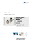
Figure D.1 shows the layout of a typical passive optical network (PON).
Exchange/office
External
Customer
Switch
ONU
Services
OLT
ONU
Services
Splitters
Fibre
Copper
OLT
Optical line termination
ONU
Optical network unit
Figure D.1 – PON (passive optical network)-based system
D.4.7
General considerations and examples
a) The assessment of hazard levels should always consider reasonably foreseeable fault
conditions (see 4.8.3) resulting from random failures in hardware components and
systematic failures (e.g. failure of software controlling the APR function). Consequently, it
may be necessary to include multiple fault conditions: a determination of the probability of
such conditions occurring is to be conducted by the responsible organization.
NOTE Whereas IEC 60825-1 refers to single fault conditions, it may be reasonably foreseeable that more
than one fault will combine to cause a dangerous situation.
26
IS 14624 (Part 2) : 2012
IEC 60825-2 : 2005
b) Service conditions often result in higher hazard levels (see Clause 5). These should be
considered by the responsible organization and persons. Examples are: introduction of
high power or amplified optical time domain reflectometer pulses into an operating fibre
network; failure or overriding of the APR (see 4.7.1e).
c) Changing of components, system parameters or the network structure may result in
changed hazard levels. Examples are: replacement of conventional bundled fibre cables
by ribbon cables (this may be beyond the direct supervision of the network manager);
change of the modulation scheme; change in transmitter circuit pack power or wavelength;
addition/change of optical amplifiers, etc.
D.5
Fault analysis – Explanation and guidance
Fault analysis is necessary for systems where the optical output is dependent on the integrity
of other components and the performance of the circuit design. It is recommended that the
manufacturer or operator should carry out a fault analysis.
D.5.1
Definitions
For the purpose of this Clause D.5, the following definition applies.
FITs
an indicator of reliability defined as the number of failures per 10 9 h
D.5.2
Fault analysis
Hazard levels are assessed under reasonably foreseeable fault conditions. The purpose of
fault analysis is to identify failures in the optical control circuits that could have significant
consequences affecting the assigned hazard level. For example, it is permitted for the lasers
used in locations with hazard level 1M to emit optical power exceeding the upper limit of
hazard level 1M under normal operating conditions, if an adequate APR feature is provided.
However, in case of a fibre break, the accessible radiation is reduced so that it is within the
limits of hazard level 1M. If however a fault in a component in the laser drive circuit or in the
APR were to result in radiation exceeding the limits for hazard level 1M, then a higher hazard
level would have to be assigned.
An APR feature can comprise both hardware and software components: both components
should be taken into account when determining the reliability of the APR feature.
D.5.3
Fault probability levels
No system is 100 % fail-safe since there is always a non-zero probability that failures will
occur. To quantify the risk of exposure to hazardous radiation, OFCS should be subject to
fault analysis using recognized techniques.
D.5.4
Commonly used fault analysis techniques
Commonly used fault analysis techniques are:
–
simulation of those faults that could be expected under reasonably foreseeable conditions;
–
failure modes effects and criticality analysis (FMECA, see IEC 60812 [1]);
–
consequence analysis (see the IEC 61508 series of standards [5]).
27
IS 14624 (Part 2) : 2012
IEC 60825-2 : 2005
D.5.5
Failure modes effects and criticality analysis
If the chosen method of fault analysis is failure modes effects and criticality analysis then the
probability of exceeding the accessible emission limits (under reasonably foreseeable
circumstances) for the target hazard level should not exceed 500 FITs. It is recommended
that the manufacturer or operator should carry out a fault analysis.
NOTE On the basis of 500 FITs and the estimated amount of time an engineer works on live fibres throughout his
working life, the incident rate for the risk of injury to the eye is less than five HITs. (HITs is the number of hazard
incidents per 10 9 h. For example in the UK, the Health and Safety Executive considers an occupational risk of less
than 5,43 HITs for accidents to be trivial.).
D.5.5.1
Example of FMECA analysis for a simple laser drive circuit
The purpose of the analysis is to provide a quantitative measure of the probability of the
optical power exceeding Class 1M AEL. The following example illustrates one recommended
method.
Consider the simple circuit in Figure D.2.
5V
LM1
IC
Polarisation
R2
TR1
Modulation
C1
R1
Figure D.2 – Simple laser drive circuit
D.5.5.1.1
Step 1: identify critical components
From circuit diagrams and parts lists, identify all the components likely to affect the laser
module. Typically, these include mean power control circuitry, data modulator and threshold
bias generator. Include automatic power reduction (APR) circuits in the analysis if the function
of the APR is to achieve the intended classification, or if an APR component failure could
cause a significant increase in the accessible power.
28
IS 14624 (Part 2) : 2012
IEC 60825-2 : 2005
D.5.5.1.2
Step 2: identify component failure modes
Construct a table listing the components, their circuit identifier and their most likely failure
modes as shown in Table D.3 below.
Table D.3 – Identification of components and failure modes (example)
Circuit ID
LM1
Component
Uncooled laser
Failure mode
Beta
Comments
Increase in output
Decrease in output
No output
TR1
R1
BFR 96 Mullard
Short circuit
<500 mW NPN
Open circuit
47R 2 %
Short circuit
0,25 W
Open circuit
Parameter drift
R2
3K9 2 %
Short circuit
0,25 W
Open circuit
Parameter drift
C1
0,47 µF 10 %
Short circuit
50 V
Open circuit
Parameter drift
The US Department of Defense Reliability Analysis Center (RAC) publication [2] gives a list of
likely failure modes. Include a column for comments and request an explanation of the likely
outcome of the failure from the engineers consulted (see step 3).
D.5.5.1.3
Step 3: determine beta values
Circuit designers or repair engineers are the best people to consult for this task, since it
requires a knowledge of how each component operates in the circuit.
Beta values depend on the criticality of the failure mode. A simple analysis assigns a
probability figure to the beta value by considering just three categories, as illustrated in
Table D.4.
Table D.4 – Beta values (example)
Does the failure mode cause the laser
power to exceed Class 1M AEL?
Beta value
Yes
1
No
0
Maybe
0,5
The consulted engineers may be able to give better estimates for the beta values.
It is good practice to simulate fault conditions whenever possible.
29
IS 14624 (Part 2) : 2012
IEC 60825-2 : 2005
D.5.5.1.4
Step 4: determine failure rates
The next step is to determine base failure rates for each component and apportion failure
rates to failure modes. This information can be obtained from e.g. the following sources:
–
data obtained by the analysis of in-service failures,
–
BT Handbook of Reliability Data, HRD5 [3] (provides intrinsic failure rates for generic
component types at the upper 60 % confidence limit),
–
RAC publication [2] (lists the apportionment of failure rates to failure modes),
–
Mil-HDBK 217 [17], and
–
RAC publication NPRD [14].
For example, HRD5 lists the base failure rate ( λ base ) for a silicon small signal bipolar
transistor as eight FITs, and the RAC publication lists the apportionment of failure modes ( α )
as 73 % for short circuits and 27 % for open circuits. Insert the values into the appropriate
columns in the spreadsheet.
Determine the system failure rate by multiplying the columns horizontally and then add
vertically. The overall failure rate represents the probability of the system exceeding the
intended classification. This is illustrated in the following Table D.5.
Table D.5 – Determination of failure rates (example)
Circuit
ID
LM1
TR1
R1
R2
C1
Component
Uncooled laser
Failure mode
Beta
λ base
α
Product
Increase in output
1
500
0,05
25,0
Decrease in output
0
500
0,65
0
No output
0
500
0,30
0
BFR 96 Mullard
Short circuit
1
8
0,73
5,84
<500 mW NPN
Open circuit
0
8
0,27
0
47R 2 %
Short circuit
1
0,2
0,05
0,01
0,25 W
Open circuit
0
0,2
0,84
0
Parameter drift
0,5
0,2
0,11
0,01
3K9 2 %
Short circuit
1
0,2
0,05
0,01
0,25 W
Open circuit
0
0,2
0,84
0
Parameter drift
0,5
0,2
0,11
0,01
0,47 µF
Short circuit
1
0,3
0,49
0,15
10 % 50 V
Open circuit
0
0,3
0,29
0
Parameter drift
0,5
0,3
0,22
0,03
Overall failure rate = 31,06 FITs
30
Comments
May result from
fibre movement
Chip failure
I laser limited by R1
(may still be safe,
see below)
IS 14624 (Part 2) : 2012
IEC 60825-2 : 2005
In this example (assuming 5 V power rail), the maximum laser current is limited by R1 to
about 35 mA. This is unlikely to result in a 1,5 µm laser exceeding the Class 1M limit. In other
cases, this is not always applicable, and reference should be made to the laser data sheet
and individual component values.
In similar examples, where a component failure is significant only if accompanied by
simultaneous independent failures in other components, a simple summation of FITs for these
components may not be appropriate.
D.5.6
Consequence analysis
The IEC 61508 series of standards, Functional safety of electrical/electronic/programmable
electronic safety-related systems [5], is one example of a standards-based approach that can
be used to quantify the reliability of automatic power reduction (APR) safety systems. In the
scheme specified by IEC 61508-1, requirements for a safety-related control system are
categorised into one of four safety integrity levels (SIL). Depending on the SIL, different
requirements apply. According to IEC 61508-1, hardware random failures and systematic
failures have to be taken into account.
–
Hardware random failures can be calculated using reliability data.
–
Systematic failures take into account the possibility of design failures, failures due to
environmental stress or influence and operational failures.
NOTE 1 The following is the SIL definition from IEC 61508-1: Discrete level (one out of possible four) for
specifying the safety integrity requirements of the safety functions to be allocated to the
electrical/electronic/programmable electronic safety-related systems, where safety integrity level 4 has the highest
level of the safety integrity and safety integrity level 1 has the lowest.
NOTE 2 Where programmable electronic devices are used to control hazard levels it is recommended that the
IEC 61508 series of standards should be applied. If the system is purely hardware it can be analysed using familiar
techniques such as FMECA.
The standard provides several example methods how an “application sector”, like OFCS,
could determine a recommended safety integrity level for specified product hazards. The
following is a hypothetical and very conservative example of an approach for determining a
SIL level. It is based on the “risk graph” method in Annex D of IEC 61508-5.
D.5.6.1
Example for consequence analysis
Risk (with no safety-related systems in place) is considered to be a function of the frequency
of the hazardous event and the consequences of the event. For this example, a risk graph
method is used to determine the SIL value. The figure below is the risk graph taken from one
of the IEC 61508 standards.
31
IS 14624 (Part 2) : 2012
IEC 60825-2 : 2005
C1
Starting point
for risk reduction
estimation
F1
C2
F2
C3
P1
P2
P1
P2
F1
F2
C4
W3
W2
W1
a
–
–
b
a
–
c
b
a
d
c
b
e
d
c
f
e
d
g
f
e
h
g
f
Necessary
minimum risk
reduction
C = Consequence risk parameter
F = Frequency and exposure time risk
parameter
P = Possibility of avoiding hazard risk
parameter
W = Probability of the unwanted
occurrence
a, b, c … h = Estimates of the required risk
reduction for the SRSs
–
a
b, c
d
e, f
g
h
a, b, c, d, e, f, g, h represent the
necessary minimum risk
reduction. The link between the
necessary minimum risk
reduction and the safety integrity
level is shown in the table.
Safety integrity level
No safety requirements
No special safety
requirements
1
2
3
4
An E/E/PE SRS is not
sufficient
Figure D.3 – Risk graph example from IEC 61508-5 Clause D.5
D.5.6.1.1
Step 1 – Consequence evaluation
In the 61508 standard, four consequence levels are classified as shown in Table D.6 below.
In the case of OFCS, for skin or eye damage, the consequence risk level could very
conservatively be assigned C 2 .
Table D.6 – Consequence classification from IEC 61508-5 Table D.1
Consequence Risk Level
D.5.6.1.2
Classification
C1
Minor Injury
C2
Serious permanent injury to one or more persons; death to one person
C3
Death to several people
C4
Very many people killed
Step 2 – Frequency evaluation
In the IEC 61508 series of standards, frequency and exposure time in the hazardous zone
must be assessed and can be assigned one of two values as specified in Table D.7 below.
A very conservative estimate for an OFCS example is an assignment of risk level F 2.
32
IS 14624 (Part 2) : 2012
IEC 60825-2 : 2005
Table D.7 – Frequency classification from IEC 61508-5 Table D.1
Classification
Frequency of, and exposure time
in, the hazardous zone – Risk
Level
D.5.6.1.3
F1
Rare to more often exposure in the hazardous zone
F2
Frequent to permanent exposure in the hazardous zone
Step 3 – Evaluation of the possibility of avoiding the hazard
In the standard, the possibility of avoiding the hazardous event can be assigned one of two
values as specified in Table D.8 below. In this example, an assignment of risk level P1 is
made.
Table D.8 – Possibility of avoiding hazard classification from IEC 61508-5 Table D.1
Possibility of avoiding the
hazardous event – Risk level
D.5.6.1.4
Classification
P1
Possible under certain conditions
P2
Almost impossible
Step 4 – Evaluation of the probability of the hazardous event taking place
without any safety-related systems
The last assignment is the probability of the hazardous event taking place without any safetyrelated systems, i.e. probability of unwanted occurrence (see Table D.9 below). For this
example the risk level range of W 1 -W 3 is assigned.
Table D.9 – Classification of the probability of the unwanted occurrence
from IEC 61508-5 Table D.1
Probability of the unwanted
occurrence risk level
Classification
W1
A very slight probability that the unwanted occurrences will come to pass and
only a few unwanted occurrences are likely
W2
A slight probability that the unwanted occurrences will come to pass and a
few unwanted occurrences are likely
W3
A relatively high probability that the unwanted occurrences will come to pass
and frequent unwanted occurrences are likely
D.5.6.1.5
Step 5 – Mapping onto the graph
Mapping these parameters onto the risk graph (Figure D.3 above) yields, under the most
conservative conditions, an assignment of a reliability level of SIL 1 for a skin or eye hazard.
(The other methods described in the IEC 61508 series of standard also converge to SIL 1
using the same criteria.).
33
IS 14624 (Part 2) : 2012
IEC 60825-2 : 2005
D.5.6.1.6
Step 6 – Determination of the reliability of the APR system
In the following steps only SIL 1 has been considered. For SIL levels other than 1, refer to the
IEC 61508 series of standards. For these SIL levels hardware random failures, hardware fault
tolerance and the safe failure fraction should be taken into account according to IEC 61508-2.
The SILs are presented as two sets of number ranges – one set for high demand mode and
one set for low demand mode for the safety device. After installation, optical fibre systems are
seldom disturbed in any fashion that would unintentionally break or open the optical path.
Therefore, there would be a very infrequent need for the automatic power reduction (APR)
system to shut down or reduce the optical power. In the terminology of the IEC 61508 series,
the APR would operate in a “low demand mode” (see definitions in Table D.10 below).
NOTE For example, mean time between failures for optical fibre cables have been determined to be in the range
of 2 years to greater than 160 years. See Tables 1 and 2 in Cochrane and Heatley [18].
Table D.10 – Modes of operation – Definitions from IEC 61508-4, 3.5.12
Term
Definition
Mode of operation
Way in which a safety-related system is intended to be used, with respect to the
frequency of demands made upon it, which may be either:
Low demand mode
where the frequency of demands for operation made on a safety-related system is
no greater than one per year and no greater than twice the proof-test frequency; or
High demand or continuous
mode
where the frequency of demands for operation made on a safety-related system is
greater than one per year or greater than twice the proof-check frequency.
NOTE 1 High demand or continuous mode covers those safety-related systems which implement continuous control
to maintain functional safety (e.g. a pressure regulator valve).
For a SIL Level 1 system the target failure rate for a hazardous situation is between 10 –1 and
10 –2 . This target failure rate can be achieved by several solutions. Examples include APR,
mechanical solutions and external risk reduction.
In this example, APR is chosen and the probability that APR fails to reduce the power should
be less than 0,1 (see Table D.11).
Table D.11 – SIL values from 7.6.2.9 of IEC 61508-1
Safety integrity
level
Low demand mode of operation
(Average probability of failure to perform its design function
on demand)
4
≥10 –5 to <10 –4
3
≥10 –4 to <10 –3
2
≥10 –3 to <10 –2
1
≥10 –2 to <10 –1
34
IS 14624 (Part 2) : 2012
IEC 60825-2 : 2005
Concerning random hardware failures the SIL level or probability of failure of an automatic
power reduction system is the APR unavailability. If the APR is continually monitored with
alarms to alert to a malfunction of the APR or periodically tested, this unavailability is
determined by both the APR equipment reliability and the operator repair time (mean time to
repair or MTTR) in the event of an APR failure. Equipment reliability is often expressed as FIT
rate (failures in 10 9 hours). Consider the following equation:
SIL level = APR unavailabi lity =
FIT rate × MTTR
10 9
(D.1)
SIL level
thus FIT rate =
× 10 9
MTTR
where
SIL level
is failures/demand,
MTTR
is mean time to repair in hours and
10 9
is the conversion from failure rate in failures/hour and FITs in failures/10 9 hours.
The following figure D.4 shows the relationship between FIT rate and mean time to repair a
failed safety system. The range for SIL level 1 safety systems has been highlighted.
FIT rate required to meet safety integrity levels
FIT rate (failures/109 h)
100 000 000
SIL 1
1 000 000
10 000
100
1 month
1 day
1
1
10
100
1 year
1 000
10 000
Mean time to repair (h)
Figure
D.5.6.1.7
D.4 – Graph of FIT rate and mean time to repair
Step 7 – Reducing the risk from systematic failures
For SIL 1, IEC 61508-2 and IEC 61508-3 highly recommend at least the following methods to
reduce systematic failures:
a) program sequence monitoring, e.g. watchdog, logical monitoring of program sequence,
temporal monitoring with online check;
b) software design using structured methods, e.g. JSD, MASCOT, SADT, Yourdon;
35
IS 14624 (Part 2) : 2012
IEC 60825-2 : 2005
c) measures against voltage breakdown, voltage variations, overvoltage, low voltage;
d) separation of electrical energy lines from information lines;
e) increase of interference immunity;
f)
measures against the physical environment, e.g. temperature, humidity, water, vibration,
dust, corrosive substances;
g) measures against temperature increase, e.g. temperature sensor, fan control, thermal
fuse, temperature alarm, forced air cooling and status indication;
h) spatial separation of multiple lines carrying duplicated signals;
i)
modification protection, e.g. plausibility check of signals or detection by automatic start-up
tests.
For further information and details to the above mentioned methods see IEC 61508 [5],
Parts 2 and 3.
D.5.6.1.8
Fit rate determination
The reliability of the APR system is a continuum that is dependent on the responsible use and
maintenance of these systems. For APR functions with a very low FIT rate there is no
maintenance of the APR function needed if the product is taken out of service within the
specified lifetime of the APR function. For all other systems the APR unavailability, and
consequently the FIT rate, is dependent on the possibility that any failure of the APR can be
detected and the operator alerted in a reasonable time for repair, as well as the
responsiveness of the operator to respond to any alarms that would indicate a failure in the
APR.
Since equipment manufacturers do not have control over the maintenance of their systems, it
may be useful to propose specific FIT rates – rather than the combination of SILs and mean
time to repair (Figure D.4). Manufacturers are likely to supply APR systems that either 1) have
frequent or continuous diagnostic testing (proof testing) or 2) are not tested or monitored. For
continuous diagnostic testing, monitoring, and alarming it is likely that a failure in optical fibre
communications systems would be repaired within one day, therefore MTTR = 24 hours.
Systems that do not test the safety-related systems may operate unattended for long periods,
but sometimes these systems are likely to be upgraded, repaired, tested or replaced every
couple of years. Therefore, the mean time to repair can sometimes be considered to be
(10 4 h), or MTTR = 10 4 h, which is in the order of one year.
Table D.12 – Determination of equipment monitoring classification
Diagnostic testing and monitoring
of safety-related system
Classification
Mean time to
repair
M1
Frequent or continuous diagnostic testing and
monitoring performed on the safety-related system
1 day (24 h)
M2
No monitoring, but frequent diagnostic testing
1 year (10 4 h)
M3
No monitoring and no testing; system is taken out
of service before the specified end of life of the
APR
20 years (2x10 5 h)
36
IS 14624 (Part 2) : 2012
IEC 60825-2 : 2005
With this information, the FIT rate can now be determined. As an example, consider a
communication system operating at 1 550 nm where the optical power under normal operation
(no fault detected) exceeds Class 1M but is below the upper limit of Class 3B. Let us say that
we wish to enable the OFCS to operate in an unrestricted location. To facilitate this it is
necessary for the radiation accessible under reasonably foreseeable fault conditions to be
limited to hazard level 1, and, given the Class of laser emitter, an APR system is needed.
The maximum permitted FIT rate should be assigned as the upper limit of a SIL 1 level
system. From Equation (D.1) and Figure D.4 above, it can be seen that the minimum
requirement (i.e. the maximum acceptable FIT rate) would be 4 × 10 6 FITs for a continuously
diagnosed system with a mean time to repair (MTTR) of 24 h, 10 4 FITs for a system with a
MTTR of 1 year, and 500 FITs for a system without continuous diagnostics.
FIT rate specifications can similarly be determined for other consequence risk levels (see the
IEC 61508 series).
Table D.13 – FIT rates from example above
FIT Rate
Consequence
Safety
integrity
level
SIL 1
D.6
M1
(Continuous
diagnostics)
M2
(Frequent
testing)
M3
(No
monitoring)
<4x10 6
<10 4
<500
Serious permanent injury to one or
more persons; death to one person –
e.g. retinal damage, small fire (C 2 )
Suggested working practices
The following working practices may be regarded as examples of good practice, and are
recommended when working with OFCS. Different working practices may apply in different
circumstances.
D.6.1
General working practices
The following working practices may be regarded as good practice when working on an
OFCS:
Viewing fibre
Do not stare with unprotected eyes or with any unapproved collimating
device at the fibre ends or connector faces, or point them at other people.
Viewing aids
Use only approved filtered or attenuating viewing aids.
Fibre ends
(single or
multiple)
Any single or multiple fibre end(s) found not to be terminated (for example,
matched, spliced) should be individually or collectively covered with material
appropriate for the wavelength and power when not being worked on. They
should not be readily visible and sharp ends should not be exposed.
Suitable methods for covering include the use of a splice protector or tape.
Always attach end caps to unmated connectors.
37
IS 14624 (Part 2) : 2012
IEC 60825-2 : 2005
Ribbon fibres
Do not cleave ribbon fibres as an unseparated ribbon, or use ribbon splicers,
unless authorized.
Test cords
When using optical test cords, the optical power source should be the last to
be connected and the first to be disconnected.
Fibre off-cuts
Collect all fibre off-cuts and dispose of them in an approved container. The
container itself should be disposed of in an approved manner.
Maintenance
Follow only approved instructions for operating and maintaining the system
being worked on.
Cleaning
Use only approved methods for cleaning and preparing optical fibres and
optical connectors.
Modification
Do not make any unauthorized modifications to any OFCS or associated
equipment.
Board
extenders
Board extenders should not be used on optical transmitter cards. Do not
power optical sources when they are outside transmitter racks.
Label damage
Report damaged or missing optical safety labels to line management.
Key control
For equipment with key control, the keys should be placed under the control
of a person appointed by management who should ensure their safe use,
storage and overall control. Spare keys should be retained under strict
control procedures by a nominated line manager.
Test
Equipment
Use test equipment of the lowest class necessary and practical for the task.
Do not use test equipment of a higher class than the location hazard level.
Signs
Area warning signs are required for locations exceeding hazard level 1M.
Area signs may be displayed in locations of lower classification.
Alarms
System alarms, especially those indicating that the APR or any other safety
system is inoperable, should be responded to so that repair takes place
within specified time.
D.6.2
Live working practices for hazard levels 1, 1M, 2, 2M and 3R
When working on live/energized systems (e.g. when optical signals are being transmitted
along the fibre of an OFCS) it is recommended that the working practices listed in D.6.1 be
used.
D.6.3
Working practices for hazard level 3B
Working on an energized system (sometimes referred to as ‘live working’) in locations with
hazard level 3B allocated is not recommended.
Responsible and adequate OFCS safety and training programmes should be established and
maintained by management. Personnel engaged in the installation and servicing of OFCS
should observe all rules, and report to management any potentially unsafe conditions or
abnormal exposures to optical radiation.
38
IS 14624 (Part 2) : 2012
IEC 60825-2 : 2005
If working on energized systems in locations with hazard level 3B is not permitted (as
described above), then the following working practices should be used:
–
all general practices defined in D.6.1;
–
the equipment generating the optical radiation should be de-energized, thereby deenergizing the OFCS (as detailed in D.6.4);
–
check that there is no optical power in the fibre by using an approved optical power meter
capable of withstanding the highest power transmitted in the system without damage;
–
cover the ends of all exposed fibres not being worked on. Always ensure unmated
connectors are appropriately attenuated, using the in-built connector shutter mechanism
or an end cap;
–
use only indirect viewing aids (for example televised or shadow imaging splicing
machines). Do not use microscopes or eye loupes without authorization;
–
when using optical test cords, the optical power source should be the last to be connected
and the first to be disconnected.
D.6.4
Formal power-down and power-up procedure for hazard level 3B
When de-energizing an OFCS (if working on energized systems is not permitted), the
following procedure should be adopted.
a) A nominated person at an optical power source should:
–
have been trained to an appropriate level on the type of equipment which has to be
switched on and off;
–
be conversant with the instructions and safety requirements relating to the previous
paragraph and with any additional local instructions and circumstances;
–
have a responsible attitude to safety.
b) Nominated persons should be appointed by line management and be notified of their
appointment.
c) A list of nominated persons at each installation should be recorded and prominently
displayed.
d) Before starting work, the person authorized to carry out the work (the originator) should:
–
contact a nominated person at the appropriate optical power source and request that
the power on the relevant fibres be switched off;
–
on duplex systems, a nominated person should be contacted at each end;
–
on being informed that the power has been switched off, complete the necessary
forms, which should be retained by the originator. These forms need not be completed
if the originator and the nominated person are one and the same;
–
verify (with an energized/live fibre identifier or optical power meter) that the power is
off;
–
on completion of the work, inform a nominated person at the appropriate optical power
source(s).
39
IS 14624 (Part 2) : 2012
IEC 60825-2 : 2005
e) On receipt of a request from an originator to switch off an optical power source, the
nominated person should:
–
record the time and date of the request and the details of the originator. Forms should
be kept on file at the location of the optical source;
–
switch off the appropriate power source (with key control, if fitted);
–
complete the warning label and affix it to the appropriate station equipment at the point
of disconnection, for example equipment rack, distribution frame; a label should be
attached for each originator;
–
contact the originator and give him the job number and the time that the source was
switched off;
–
on being informed that the work has been completed, record the details appropriately
and remove the warning label from the equipment before re-energizing the source.
When more than one originator requires the same power source to be switched off, the
source should not be re-energized before all work is completed.
D.7
Maximum output power during shutdown
Table D.14 lists the maximum output power (mW), during the shutdown time, for single mode
OFCS which shut down to lower hazard level limits in 1 s for unrestricted locations and 3 s for
restricted and controlled locations (see 4.8.2). Engineering requirements as outlined in
Annex B should be employed as appropriate to that lower hazard level.
The equation used to derive Table D.6 was:
NOHD =
ω0πd
×
2 2λ
1
P
ln
2
P − πd MPE
4t
An alternative form of this equation is:
P=
πd 2MPE
×
4t
1
πω0d
1 − exp− 0,125
λNOHD
where
ω0
is the mode field diameter (1/e 2 power density) (m);
P
is the total power in fibre (W);
d
is the limiting aperture diameter (m);
MPE
is the maximum permissible exposure (Jm –2 );
NOHD is the nominal ocular hazard distance (m);
t
is the shutdown time (s);
λ
is the wavelength (m).
40
2
IS 14624 (Part 2) : 2012
IEC 60825-2 : 2005
Table D.14 – Examples of power limits for OFCS having automatic power reduction to
reduce emissions to a lower hazard level
Maximum
power output
unrestricted
mW
Maximum
power output
restricted
mW
Maximum
power output
controlled
mW
Shutdown
times
Measurement
distance
nm
Fibre mode
field
diameter
µm
s
m
980
7
9,4
–
–
1
0,1
980
7
–
7,2
–
3
0,1
980
7
–
–
39
3
0,25
1 310
11
78
–
–
1
0,1
1 310
11
–
59
–
3
0,1
1 310
11
–
–
314
3
0,25
1 400 ...
1 500
11
650
–
–
1
0,1
1 400 ...
1 500
11
–
288
–
3
0,1
1 400 ...
1 500
11
–
–
1 774
3
0,25
1 550
11
1 273
–
–
1
0,1
1 550
11
–
428
–
3
0,1
1 550
11
–
–
2 640
3
0,25
Wavelength
NOTE The fibre parameters used are the most conservative case. Listed figures for λ = 1 310 nm ...
1 550 nm are calculated for a fibre of 11 microns mode field diameter (MFD) and those for λ = 980 nm are for
7 µm MFD.
Many systems operating at 1 550 nm with the use of erbium doped fibre amplifiers (EDFAs) pumped by
1 480 nm or 980 nm lasers use transmission fibres with smaller MFDs. For example, 1 550 nm dispersion
shifted fibre cables have upper limit values of MFD of 9,1 µm. In this case, the maximum power outputs for
unrestricted and restricted areas at 1 480 nm and 1 550 nm are 1,44 times the values in Table D.14, and
those for controlled areas at 1 480 nm and 1 550 nm are 1,46 times the values in Table D.14.
41
IS 14624 (Part 2) : 2012
IEC 60825-2 : 2005
Annex E
(informative)
Guidance for service and maintenance
E.1
Tests and measurements
E.1.1 Tests, measurements and operations in cable ducts and switching centres should be
considered as service or maintenance operations. Wherever possible, diagnostic tests should
be carried out in such a way as not to increase the hazard level at any location. It may be
necessary to have administrative controls which, in some cases, may involve a permit to work
system. When connecting test equipment, due regard should be given to establishing the
actual power levels introduced into the system in assessing the hazard.
E.1.2 The operating organization should develop and maintain clearly defined conditions
under which the automatic power reduction feature can be overridden.
When the automatic power reduction feature has been overridden, the hazard level should be
reassessed by the operating organization. The appropriate safety precautions described
in 5.2 and its associated subclauses should be taken as appropriate to the reassessed hazard
level.
E.1.3 Any viewing optics for fibre examination and splicing should be selected so that they
reduce exposure to below the relevant maximum permissible exposure (MPE) and should be
approved for use by the operating organization.
NOTE The marking of approved viewing optics with a label by the operating organization may be an acceptable
solution.
E.1.4 Wherever reasonably practical, servicing, maintenance and repair should be carried
out with no power propagating in the fibre. Where this is not reasonably practicable, the
system should be operated at the lowest power consistent with the functional need.
E.1.5 The operating organization should establish work practices preventing human
exposure to radiation in excess of the relevant MPE.
E.2
E.2.1
Safety precautions
General remarks
E.2.1.1 In locations where, during service or maintenance, optical or laser radiation above
the MPE levels may be encountered (e.g. during switching, in controlled locations),
appropriate eye protection should be provided.
42
IS 14624 (Part 2) : 2012
IEC 60825-2 : 2005
E.2.1.2 Before working on any optical fibre cable or system, the end-user should check the
hazard level at accessible locations. In the case of systems that are installed and activated,
the hazard level should be identified at accessible locations by warning labels. Precautions
appropriate to the hazard level should be taken on systems that are known to be, or could
become, operational. During installation, hazard level labels may not have been provided yet
and, in their absence, precautions appropriate to the classification of any transmitters or test
equipment containing optical sources connected to the fibre should be used.
E.2.1.3 During the installation or testing of an optical fibre cable or network it is
recommended that only test equipment having an output designated hazard level 1, 1M, 2 or
2M per IEC 60825-2 or Class 1, 1M, 2 or 2M per IEC 60825-1 be used.
For optical fibre communications systems located in a restricted location or a controlled
location it is possible to use test equipment with higher optical output powers, providing the
accessible fibre ends and connectors at all locations are secured and labelled with the
appropriate hazard level before testing proceeds.
E.2.1.4
Entry points to controlled areas with a hazard level of 3B should have:
–
a sign bearing the warning label according to Figure 14 in IEC 60825-1 and the
explanatory label of Figure 15 of IEC 60825-1 bearing the words "Hazard level 3B“;
–
a sign limiting access to authorized persons only and explaining the existence of a
potential hazard.
E.2.1.5
Each person engaged in the operation, installation or service of an OFCS should:
–
observe all rules, procedures and practices established for the safe operation of OFCS;
–
immediately notify the supervisor of conditions or practices that have the potential to
cause personnel injury or property damage;
–
immediately report to the supervisor any known or suspected abnormal exposure to optical
radiation.
E.2.2
Precautions in locations with hazard levels 1M, 2M, 3R and 3B
E.2.2.1 Where possible, optical transmission or test equipment should be shut down, put into
a low-power state or disconnected before any work is done on exposed fibres, connectors etc.
In that case, unintentional switching on should be prevented by a remote control switch or
another suitable method. The status of the line (power on or off) should be clearly indicated.
E.2.2.2 Persons having access to any energized fibre end or connector end should be
instructed not to view such points directly. Under all circumstances, only those viewing aids
which provide the appropriate level of attenuation should be used.
43
IS 14624 (Part 2) : 2012
IEC 60825-2 : 2005
E.2.2.3 Only staff who have attended an optical fibre safety training course should be
permitted to work on OFCS in a location with hazard level 3B.
E.2.2.4 Staff installing, operating or maintaining OFCS and any associated test equipment in
locations with hazard level 3B should ensure that untrained personnel are adequately
protected.
E.2.2.5 It is possible that high loss points in the system could suffer from high temperatures
when extremely high power levels (hundreds of mW to several W) are injected into the fibre.
NOTE
An example of such a system is one that uses distributed Raman amplification technology.
The high temperature may lead to dangerous situations in equipment and offices. Therefore,
in systems that normally transmit extremely high power the following action is recommended:
connectors should be cleaned very carefully so that the loss induced by connectors, splices or
bending at any point is reduced as far as possible.
E.2.3
Training programme
The employer of staff installing or maintaining OFCS should establish and maintain an
adequate programme for the control of fibre optic hazards. Safety and training programmes
should be instituted for staff working on fibre optic communication systems with a hazard level
of 3B. Such programmes should be directed by individuals competent in the field of laser and
OFCS safety. The programmes should provide, as a minimum:
–
background information on OFCS;
–
safety information concerning the laser classification system and hazard levels.
44
IS 14624 (Part 2) : 2012
IEC 60825-2 : 2005
Annex F
(informative)
Clarification of the meaning of “hazard level”
In this annex, the difference between “laser class” defined in IEC 60825-1 and “hazard level”,
defined in IEC 60825-2 is further clarified.
F.1
Class
The word “class” refers to a scheme by which, based on emission levels, a product or internal
emitter can be grouped with respect to its safety. These levels are described in the accessible
emission limit tables in IEC 60825-1. Classes range from Class 1, which is safe under
reasonably foreseeable conditions, to Class 4, which is potentially the most hazardous case.
In IEC 60825-1, the classification of products is based on reasonably foreseeable operating
conditions including single fault conditions.
F.2
Hazard level
“Hazard level” is a term used in this standard which refers to the potential hazard from laser
emissions at any location in an end-to-end fibre optic communication system that may be
accessible during use or maintenance or in the event of a failure or fibre disconnection. The
assessment of the hazard level uses the class accessible emission limit tables described in
IEC 60825-1. The assessment of hazard level is described in 4.8.1. The assessment can be
an actual measurement or be based upon calculation of emitting powers and known time
constants.
Annex A of this standard gives the following additional clarification: “A whole OFCS will not be
classified in the same way as required by IEC 60825-1. This is because, under intended
operation, the optical radiation is totally enclosed and it can be argued that a rigorous
interpretation of IEC 60825-1 would give a Class 1 allocation to all systems, which may not
reflect the potential hazard accurately.” Based upon this statement, a complete OFCS can be
regarded as a Class 1 laser product because, under normal conditions, the emissions are
completely enclosed (like a laser printer) and no light should be emitting outside the
protective housing. It is not until the fibre becomes broken or an optical connector is
unplugged that someone might be exposed to a level of optical radiation which is potentially
hazardous (if the internal emitters or amplifier outputs are of high enough power).
Therefore, for each optical output port, the hazard level must be assessed. The hazard level
limits are dependent on the “dominant” wavelength range, taking into consideration that
IEC 60825-1 defines different limits for different wavelength ranges. Details can be found
in IEC 60825-1. Furthermore, this standard allows the use of automatic power reduction
(APR) techniques to achieve a lower (less hazardous) hazard level based on the normal
power in the fibre and the speed of automatic power reduction.
45
IS 14624 (Part 2) : 2012
IEC 60825-2 : 2005
F.3
Rationale to definitions 3.1, 3.4 to 3.11 and to Clause 4
Large portions of OFCS can sometimes be classed as "not accessible under reasonably
foreseeable conditions".
F.4
Rationale to 4.8.1 and 4.8.2
The philosophy of these subclauses is based on assumptions that already exist in Parts 1
and 2 of IEC 60825.
The clause requires that the MPE not be exceeded if any person is exposed to radiation
emerging from the port or fracture from the instant of break or disconnection. The power is
assumed to remain constant at its maximum value until the shutdown time has expired.
a) Unrestricted locations:
The 1 s shutdown for unrestricted areas is consistent with 4.8.1 of IEC 60825-2, which
states that "...the assessment of the hazard level shall take place 1 s after the reasonably
foreseeable event...”. The 100 mm distance is consistent with Table 10 of IEC 60825-1.
Even if a fibre is intentionally cut, it is highly unlikely that, within 1 s, a person can get
within 100 mm and position collimating optics be adversely exposed. Also, one must keep
in mind that optical signals are attenuated as they move down the fibre, so the output at
the failure in the unrestricted area may be considerably lower than at the transmitter or
amplifier.
b) Restricted locations:
The 3 s shutdown for restricted areas is also consistent with 4.8.1, if one assumes that
any failure of the system within a restricted area would be of an accidental nature and the
3 s limit for shutdown would be an acceptable time period "after the reasonably
foreseeable event". It is also highly unlikely that, in this time period, a person can get
within 100 mm and position collimating optics be adversely exposed. One must also keep
in mind that optical signals are attenuated as they move down the fibre, so the output at
the failure in the restricted area may be considerably lower than at the transmitter or
amplifier.
c) Controlled locations:
Persons working in locations with controlled access must have received adequate training
in laser safety, which should include an understanding that viewing a broken fibre should
not undertaken unless the system has been properly inactivated.
Rationale to Clause D.5
Annex D is informative. The use of the term "recommended" may be incorrectly construed as
forbidding the use of alternative methods of analysis. The method of fault analysis and the
adoption of a suitable safety level is the prerogative of the user.
46
IS 14624 (Part 2) : 2012
IEC 60825-2 : 2005
Bibliography
[1]
IEC 60812, Analysis techniques for system reliability – Procedures for failure mode and
effects analysis (FMEA)
[2]
Failure Mode/Mechanism Distributions 1991, FMD-91. Reliability Analysis Center, US
Dept of Defense, 1991. [Prepared by:Reliability Analysis Center, PO Box 4700, Rome
NY]
[3]
BT Handbook of Reliability Data for Components Used in Telecommunications Systems,
1995, Issue 5 [Copies available from: ILI Index House, Ascot, Berkshire SL5 7EU]
[4]
UKAS Document NIS 20: Uncertainties of Measurement for Electrical Product Testing
Draft 2, Jan 1992
[5]
IEC 61508 (all parts), Functional safety of electrical/electronic/programmable electronic
safety-related systems
[6]
IEC 60794-1-1, Optical fibre cables – Part 1-1: Generic specification – General
[7]
IEC 60794-1-2, Optical fibre cables – Part 1-2: Generic specification – Basic optical
cable test procedures
[8]
IEC 60794-2, Optical fibre cables – Part 2: Indoor cables –Sectional specification
[9]
IEC 60794-3, Optical fibre cables – Part 3: Sectional specification – Outdoor cables
[10]
IEC 60794-4-1, Optical fibre cables – Part 4-1: Aerial optical cables for high-voltage
power lines
[11]
IEC 60794-3-10, Optical fibre cables – Part 3-10: Outdoor cables – Family specification
for duct and directly buried optical telecommunication cables
[12]
IEC 60794-3-20, Optical fibre cables – Part 3-20: Outdoor cables – Family specification
for optical self-supporting aerial telecommunication cables
[13]
IEC 60950-1:2001, Information technology equipment – Safety – Part 1: General
requirements
[14]
Nonelectronic parts reliability data 1995, NPRD-95. Reliability Analysis Center (US Dept
of Defense, 1995. [Prepared by Reliability Analysis Center, PO Box 4700, Rome NY]
[15]
ITU-T Recommendation G.664, Optical safety procedures and requirements for optical
transport systems
[16]
IEC 60825-12, Safety of laser products – Part 12: Safety of free space optical
communication systems used for transmission of information
[17]
MIL-HDBK-217F, Reliability Prediction Of Electronic Equipment
[18]
COCHRANE, P. and HEATLEY, DJT. Reliability Aspects of Optical Fibre Systems &
Networks. BTTJ Special Issue on Future Telecommunication Systems & Networks,
No. 2, April 1994, Vol 12, pp. 77-92,
[also found at: http://innovate.bt.com/people/ heatledj/ papers/reliability/reliability]
___________
47
Bureau of Indian Standards
BIS is a statutory institution established under the Bureau of Indian Standards Act, 1986 to promote
harmonious development of the activities of standardization, marking and quality certification of goods
and attending to connected matters in the country.
Copyright
BIS has the copyright of all its publications. No part of these publications may be reproduced in any form
without the prior permission in writing of BIS. This does not preclude the free use, in course of implementing the standard, of necessary details, such as symbols and sizes, type or grade designations.
Enquiries relating to copyright be addressed to the Director (Publications), BIS.
Review of Indian Standards
Amendments are issued to standards as the need arises on the basis of comments. Standards are also
reviewed periodically; a standard along with amendments is reaffirmed when such review indicates that
no changes are needed; if the review indicates that changes are needed, it is taken up for revision. Users
of Indian Standards should ascertain that they are in possession of the latest amendments or edition by
referring to the latest issue of ‘BIS Catalogue’ and ‘Standards: Monthly Additions’.
This Indian Standard has been developed from Doc No.: LITD 11 (3155).
Amendments Issued Since Publication
______________________________________________________________________________________
Amendment No.
Date of Issue
Text Affected
______________________________________________________________________________________
______________________________________________________________________________________
______________________________________________________________________________________
______________________________________________________________________________________
______________________________________________________________________________________
BUREAU OF INDIAN STANDARDS
Headquarters:
Manak Bhavan, 9 Bahadur Shah Zafar Marg, New Delhi 110002
Telephones: 2323 0131, 2323 3375, 2323 9402
Website: www.bis.org.in
Regional Offices:
Telephones
Central
2323 7617
{ 2323
3841
: Manak Bhavan, 9 Bahadur Shah Zafar Marg
NEW DELHI 110002
Eastern : 1/14, C.I.T. Scheme VII M, V.I.P. Road, Kankurgachi
KOLKATA 700054
Northern : SCO 335-336, Sector 34-A, CHANDIGARH 160022
Southern : C.I.T. Campus, IV Cross Road, CHENNAI 600113
Western : Manakalaya, E9 MIDC, Marol, Andheri (East)
MUMBAI 400093
8499, 2337 8561
{ 2337
2337 8626, 2337 9120
3843
{ 260
260 9285
1216, 2254 1442
{ 2254
2254 2519, 2254 2315
9295, 2832 7858
{ 2832
2832 7891, 2832 7892
Branches: AHMEDABAD. BANGALORE. BHOPAL. BHUBANESHWAR. COIMBATORE. DEHRADUN.
FARIDABAD. GHAZIABAD. GUWAHATI. HYDERABAD. JAIPUR. KANPUR. LUCKNOW.
NAGPUR. PARWANOO. PATNA. PUNE. RAJKOT. THIRUVANATHAPURAM. VISAKHAPATNAM.
Published by BIS, New Delhi


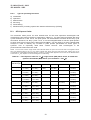
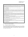


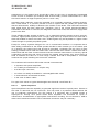
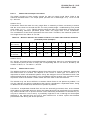
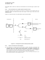
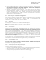

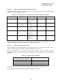
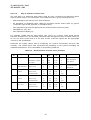

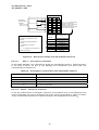
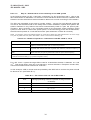
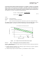
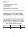

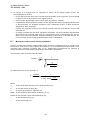
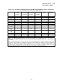


![KeyView [4823353_1.wpd]](http://vs1.manualzilla.com/store/data/005667242_1-589c8deb81b55e7c0d34a0d078158765-150x150.png)