1
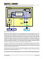
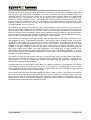
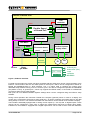
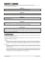
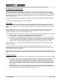
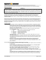
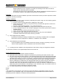
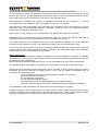
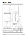
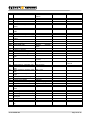
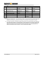
EnSonic
User Manual
Document code: 10735.USER.002
___________________________________________________________________________________________________________
EnSonic User Manual
10735.USER.0022
Document
EnSonic User Manual
Document code
10735.USER.002
Date
Oct 24, 2005
Publisher
Elster-Instromet N.V.
Rijkmakerlaan 9
B 2910 Essen
Belgium
Phone:
Fax:
Copyright
+32-3-670 0700
+32-3-667 6940
©2005, Elster-Instromet N.V., Essen, Belgium
All technical and technological information contained in this manual, including
any drawings and technical specifications remain the property of ElsterInstromet N.V. and may not be used (other than for the operation of this
product), copied, multiplied, passed on or communicated to a third party
without the prior written permission of Elster-Instromet N.V.
Trademarks
Products listed are trademarks of their respective manufacturers. Company
names listed are trade names of their respective companies
Revision History
Revision
A
B
10735.USER.002
Remark
First edition
ATEX security issues added
Name updated to Elster-Instromet
Updates & minimal changes to contents
Updates & changes to contents
Date
20/1/2004
18/8/2005
24/10/2005
Page 2 of 30
Table of Contents
Preface .............................................................................................................................................................. 4
H1 System Overview ........................................................................................................................................ 5
Introduction.................................................................................................................................................... 5
EnSonic Calculation Model ........................................................................................................................... 5
EnSonic System Setup.................................................................................................................................. 6
H2 Safety Instructions ................................................................................................................................... 11
General warnings ........................................................................................................................................ 11
Analysers in hazardous area’s .................................................................................................................... 11
System Safety Components........................................................................................................................ 12
Gas flow ................................................................................................................................................. 12
Ex-safety ................................................................................................................................................ 14
Electric safety......................................................................................................................................... 14
H3 EnSonic Operation ................................................................................................................................... 15
Power supply............................................................................................................................................... 15
Configuration software ................................................................................................................................ 15
Moisture filter draining ................................................................................................................................. 17
Parameter setting........................................................................................................................................ 17
Calibration ................................................................................................................................................... 18
Initiating a calibration ............................................................................................................................. 18
Internal Calibration Procedure ............................................................................................................... 18
Modbus configuration.................................................................................................................................. 20
Appendix B, Component Layout................................................................................................................... 23
Appendix D, LED Status Indication EnSonic Interface board.................................................................... 27
Appendix E, Dip-switch settings................................................................................................................... 28
Appendix G, Type plate ................................................................................................................................. 30
10735.USER.002
Page 3 of 30
Preface
This document describes the EnSonic Energy Measurement System and serves as a guide for configuring
and operating the EnSonic.
Throughout this document the Model 2000 flow computer which is used as a display and control unit for the
EnSonic is sometimes referred to as FC2000 or M2000.
Related documents:
‘EnSonic Installation Manual’
‘EnSonic Programmer’
‘Model 2000 Programmer’
‘Model 2000 Gas Flow Computer’
10735.USER.002
code: 10735.INST.004
code: 10735.ENSCNF.001
code: 10735.M2KCNF.001
code: Model 2000 issue 6, 202/09-02
dd 25-06-2004
dd 25-01-2004
dd 25-01-2004
dd 16-09-2002
Page 4 of 30
H1 System Overview
This chapter describes the EnSonic calculation model, the system set-up and the internal data flow.
Introduction
The EnSonic is a device capable of measuring the gross parameters of a generic natural gas at high
pressure on an almost real-time basis with a high accuracy and repeatability. The gross parameters
determined are the compressibility Z, the heating value HSR, the relative density RD, the Wobbe index Wi, all
at base conditions, and the Carbon Dioxide content xCO2. The system has been designed to operate
independently from other systems and can be installed outdoors in hazardous areas close to operational
natural gas transport systems. The EnSonic is fitted with an auto-calibration function checking the
performance and accuracy of the system at regular intervals, typically once or twice a week, with a single
calibration gas (in most situations a natural gas). The EnSonic can be powered by 230 VAC, 110 VAC or 24
VDC; data communication takes place over two RS485 serial communications ports via a Modbus RTU
protocol.
More specifications of the EnSonic are presented in appendix A.
EnSonic Calculation Model
In the EnSonic a novel calculation model has been implemented allowing the EnSonic to determine the gross
parameters of a generic natural gas using only 3 main input parameters. To be more specific, the correlative
model is based on empiric relations between the composition and the heating value of the gas; the on line
determination of the gross parameters is based on the accurate and continuous measurement of the
following input parameters, see fig 1:
1a) the Velocity of Sound, VOS_high, of the natural gas at high pressure
1b) the state of the gas in the high pressure condition: P_high and T_high
2a) the Velocity of Sound, VOS_low, of the gas at low pressure
2b) the state of the gas in the low pressure condition: P_low and T_low
3) the Carbon Dioxide content, xCO2, of the gas
VOS at high pressure
P_high & T_high
VOS at low pressure
P_low & T_low
model
based on
S-GERG
AGA-8
ISO 12213
ISO 6976
AGA-8
M-GERG
Z
Rho
Wobbe
Hv
CO2
CO2 content
intermediate
compostion
Figure 1, EnSonic Operation
The measured data acts as input for the novel and patented correlative model developed by Prof. Shouten en
Dr. Michels of the ‘Van Der Waals’ laboratory in Amsterdam. The model itself is based on the S-GERG, AGA-
10735.USER.002
Page 5 of 30
8 and ISO 12213 natural gas databases and is therefore applicable to an extremely wide range of natural
gases. Thereby, since mixtures of natural gases behave like a single natural gas, the EnSonic is able to
handle these mixtures as well.
The model is based on the fact that for natural gases the ratio between the hydrocarbons is a function of the
heating value of the gas only. Therefore the heating value and the composition of the gas can be determined
using an iterative approach. Since the model is based on a database for generic natural gases the system
cannot be used for artificial mixtures of gases or natural gases blended with high concentrations of single
component gases.
The output of the model is an ‘intermediate’ or ‘inferred composition’ which has the same gross parameters
as the natural gas being analyzed. Since the concentration of the individual components in the intermediate
composition may differ slightly from their actual concentration, the intermediate composition is not available to
the user of the system. However, it should be kept in mind that the model has been designed to determine
the gross parameters of the natural gas with high accuracy.
Finally, the gross parameters of the natural gas are calculated using the inferred composition and the wellknown ISO 6976, AGA-8 or M-GERG equations.
Since the gas is sampled on a continuous basis and the output of the system is updated once per second a
very fast and almost real time measurement system has been realized.
EnSonic System Setup
The basic system setup of the EnSonic is explained using figures 2 and 3 where the gas- and data-flow in the
system are presented. Since these figures show the standard version of the Ensonic certain components
may or may not be present in actual installations depending on the customers requirements.
The systems comes mounted in an IP 56 cabinet, a skid with sunroof can be supplied to facilitate outdoor
installation, see appendix A for the overall dimensions. The cabinet houses an explosion proof EEx-d box in
which the non Ex-safe components are mounted, the Ex-safe components are mounted outside of this box.
Appendix B presents a detailed overview of the component layout.
10735.USER.002
Page 6 of 30
Cabinet IP56
Eex-d Box
CO2
Meter
atm
3 bar
stream
selection
valve
Double Velocity of
Sound Cell
T
40 bar
pressure
transmitters
Ph
Pl
filter
back
pressure
regulators
P < 80 bar
line gas
reference
gas
vent to
atmosphere
Figure 2, EnSonic gas routing
During normal operation high pressure line gas with a pressure between 40 to 80 bara (580 to 1160 psia) is
sampled from the main transport line via a heat traced sample line with a maximum length of approx. 3 m.
After passing the (optional) membrane filter and the stream selection valve the high pressure gas flow is split
in two separate flows of different pressure (approx. 3.8 and 38 bar) using two manually adjustable
restrictions. Both flows are led into the Double Velocity of Sound Cell (: 2VOS cell or body) which
incorporates two identical sub-systems consisting of a heat exchanger and a measurement chamber (: VOS
cell) where the speed of sound of the gas is measured using state of the art ultrasonic measurement
techniques. At all times the temperature of the body is kept constant at 50 °C (122 F) using a sophisticated
temperature control system. Downstream of the low pressure VOS cell a small amount of the gas is diverted
via a third adjustable flow restriction to a Carbon Dioxide analyzer operating at atmospheric pressure.
Downstream of this analyser a flowmeter has been mounted to monitor the flow rate.
The two main gas flows through the 2VOS body are passed to manually adjustable back pressure regulators
controlling the pressure in the two cells. The reason for measuring and controlling the gas pressure
downstream of the 2VOS body is the minimisation of the upstream volume of the system. Finally, all the gas
is collected and vented into the atmosphere. A flowmeter is mounted in the main vent pipe to check for the
presence of flow during operation of the unit.
To check the performance of the system reference gas can be supplied on a regular basis by activating the
stream selection valve. By using a reference gas of known composition the EnSonic is capable to check and,
when necessary, re-adjust itself automatically.
The data flow in the system is explained using figure 3. In the centre of this figure the 2VOS cell is shown in
which the speed of sound of both the high and low pressure gas is measured using standard Elster-Instromet
10735.USER.002
Page 7 of 30
ultrasonic sensors and electronics. Since the ultrasonic measurement unit operates completely independent
from the rest of the components in the system it can be treated as a stand-alone ultrasonic meter. The
measured velocity of sound and gas velocity are sent to the EnSonic processor board via a serial RS232
communication port. Consequently, the unit can be configured and diagnosed using the standard tools
available for Instromet ultrasonic meters. Users familiar with Instromet ultrasonic metering systems can view,
log and analyse the measurement data from the ultrasonic unit independently from the operation of the
EnSonic by watching the data on one of the other serial communication ports of the ultrasonic unit, see the
connection labeled ‘service’ in figure 3.
As mentioned, the ultrasonic measurement data is made available to the processor board of the EnSonic
once per second via the RS232 port of the ultrasonic meter. It should be kept in mind that since the ultrasonic
meter sends it’s data packages to the processor board once per second independent of the state of the
EnSonic processor board, the ultrasonic meter can be regarded as being the master in this communication.
In fact, the processor board of the EnSonic just ‘listens’ to the data coming in, when the data communications
fails the EnSonic processor board will raise an alarm after a number of retries.
The temperature of the 2VOS cell is kept constant using an independent control system consisting of a Pt100 temperature sensor, a temperature transmitter, a PID controller and a dedicated heater covering the
greater part of the 2VOS cell. The temperature control is straightfoward: the temperature of the body is
measured by the temperature transmitter using the Pt-100 sensor and the measured temperature is made
available to the PID controller via the 4-20 mA current output of the temperature transmitter. The PID
controller on it’s term controls the amount of heat sent to the 2VOS cell by proportionally swichting the 24
VDC power supply of the heater. The actual temperature of the 2VOS body is made available to the
computational unit of the EnSonic via the digital HART interface of the temperature transmitter. To achieve
this, the HART address of the temperature transmitter is set to 0 (zero). The actual temperature is used in the
calculation of the gas parameters.
The pressure of both the high and low VOS cell is measured using highly accurate pressure transmitters,
data from these transmitters is sent to the computational unit via digital HART interfaces. To speed up the
communication as much as possible both pressure transmitters and the temperature transmitter are
connected to 3 separate HART interfaces.
Communication with the CO2 analyser takes place via a RS232 interface.The computational unit polls the
CO2 analyser at least once per second which on it’s term transmits the requested data to the processor
board. The data (CO2 mol% and pressure) consists of 16-bit numbers which are converted to a physical CO2
concentration and pressure by the computational unit.
The processor board has been fitted with a digital input which is used to check for the presence of reference
gas using an intrinsic safe pressure switch mounted on the pressure reducer of the reference gas. Only when
reference gas is present, the stream selection valve is allowed to switch between line and reference gas. The
stream selection valve is controlled via the digital output on the processor board. In double-block and bleed
configurations two stream-selection valves are mounted.
10735.USER.002
Page 8 of 30
EnSonic Cabinet IP56
Eex-d box
PID
controller
heater
4-20 mA
Double Speed
of Sound Cell
RS232
relay
Hart
RS232
CO2 Meter
Processor board
port 1
Interface & power
supply board
port 2
Eex-i
barrier
Hart
RS 485
MODBUS
service
Temperature
transmitter
Ultrasonic
flow meter
RS232/485
stream
selection
valve
Pt 100
empty
gas bottle
Pl
FC2000
PC
Hsr = xxxx
Hart
Ph
4-20mA (4x)
status bits (12x)
reset
calibrate
MODBUS
Figure 3, EnSonic data flow
For data communication the system has been equipped with two serial ports. During normal operation of the
EnSonic communication with the user takes place via serial port 2 which can be configured for RS232 or
RS485 and MODBUS-ASCII or -RTU operation. Port 1 is mainly used to configure the system using
dedicated setup software running on a PC. However, port 1 can also be configured to operate as a MODBUS
port (ASCII or RTU). In general port 1, which only supports the RS232 mode, is connected to a RS232/485
converter to allow for long cable lengths.
Both ports can use different Modbus registers settings which can be configured using the EnSonic setup
software.
During normal operation the Instromet FC2000 flow computer (optional) which is used as a display and
control unit is connected to serial port 2 while serial port 1 is used to configure the system and/or to log data
during startup or service. The measurement data from the EnSonic can be viewed on the FC2000 ‘s display.
The FC2000 is standardly equipped with 4 analog current outputs (4 – 20 mA) and 12 digital outputs. These
outputs can be configured in many ways to reflect the measurement data and to indicate alarm states.
Furthermore, the FC2000 is equipped with 3 digital inputs which can be used to issue reset and calibration
10735.USER.002
Page 9 of 30
commands remotely. Reset and calibration commands can also be issued locally using the keyboard of the
FC2000 or remotely via the Modbus port of the M2000.
In most installations where long cable lengths are involved the EnSonic requires a 230 VAC power supply, for
short cable lengths a 24 VDC unit can be used.
10735.USER.002
Page 10 of 30
H2 Safety Instructions
Prior to installation and operation of the EnSonic the following warnings and precautions should always be
noted.
SPECIAL NOTICE
The following warnings and precautions are intended for information only. Any international,
national, local or company codes and regulations applicable to the location of the analyser should
always be considered and applied. Elster-Instromet assumes no responsibility for compliance with
these requirements.
General warnings
WARNING !!
The EnSonic is a 230 VAC (or 115 VAC) powered apparatus. Therefore high voltage connections are located
in the EEx-e connection box and in the EEx-d housing.
WARNING !!
The external power supply of the EnSonic must be fitted with fuses with a proper value. These fuses are a
part of the electric safety of the EnSonic.
WARNING !!
Depending on the configuration of the analyser; it can weigh up to 200 kg. You should have the necessary
equipment to lift and move it.
WARNING !!
When powered the external heat tracing will warm up and reach temperatures up to 70 °C (160 F). Do not
touch uncovered parts of the heat tracing inside the cabinet.
Analysers in hazardous area’s
The analyser is designed for use in a hazardous area. The protection types used are EEx “e” (increased
safety), EEx “d” (explosion proof) and EEx “i” (intrinsic safety). Housings which are used as an EEx-d
protection housing should not be opened when a hazardous gas is present or when the unit is powered.
WARNING !!
Do not open the EEx-d ELECTRONICS HOUSING when an explosive gas atmosphere is present! Since
batteries are present on the digital boards in the EEx-d box it is not sufficient to shut off the power supply.
PRECAUTION
Before working on any electrical part of the analyser ensure that there are no hazardous gasses present in
the immediate area of the analyser, as they may create a potential for fire, explosion, damage to property and
injury to personnel. Obtain proper work permits.
10735.USER.002
Page 11 of 30
Use of pressurised (explosive) gasses
WARNING !!
The calibration gas for the analyser is flammable and may form an explosive mixture with air. Follow the
applicable safety precautions and use extreme care when making connections.
WARNING !!
Make sure that the line and sample gas pressure do not exceed the maximum inlet pressure of 80 barg.
WARNING !!
Optimal pressure for calibration and/or reference gas is 50 barg. For safety reasons make sure this pressure
never exceeds 80 barg.
WARNING !!
Gas flow through the EnSonic vent system may never obstructed since high pressure gas may built up and
dangerous situations may be created and/or components may become damaged. Although safety
components are present, a proper gas flow through the vent is of vital importance.
PRECAUTION!!
The EnSonic may be fitted with an optional moisture filter. Draining the filter involves the manual operation of
a number of valves in a distinct order. Therefore, the section on how to drain the moisture filter should be
read first. It should be noted that the handling of natural gas moisture and/or condensate is restricted to local
regulations since natural gas moisture and/or condensate contain toxic components which can seriously
harm the environment and human health.
System Safety Components
This section describes the safety components in the system and should be read carefully before installing,
operating and/or servicing the EnSonic.
The safety of the system during normal operation depends on a number of components, the function of these
components is explained using figure 4.
Typeplate
Appendix G gives a description of the type plate on the Eex-d box of the EnSonic. The information on
this type plate should be taken into account when installing, operating or servicing the components in
the Eex-d box. The type plate itself is located in the upper right corner of the cover of the Ex-proof box.
Gas flow
Although the total internal gas volume of the EnSonic is very low and the EnSonic has been designed
to handle inlet pressures upto 80 bar, the use of high pressure gas requires the addition of a number of
safety components.
The inlet of the calibration gas (: CAL input, see fig 4) is protected by the safety valve C1 which has a
setpoint of 60 bar (: 870 psi). In case of a breakdown or malfunction of the pressure regulator P1 which
controls the inlet pressure of the calibration gas, C1 reduces the pressure from bottle level to 60 bar.
The surplus of gas is vented to the atmosphere via the VENT output.
10735.USER.002
Page 12 of 30
10735.USER.002
Page 13 of 30
Figure 4, Safety components
It should be noted that the inlet of the line gas (: STREAM input) is not protected by a safety valve. It is
the responsibility of the user to supply gas with a pressure lower than or equal to 80 bar (: 1160 psi).
However, since most transport systems operate at pressures lower than approx. 65 bar extra
precautions won’t be required in most of the installations.
The drain of the optional moisture filter MF is protected by the valve V3 since metering valve N1 is not
suited for this purpose.
The CO2 analyser (: CA), a low pressure device with a maximum inlet pressure of 1200 mbar (: 17
psia) and a breakdown pressure of approx 2 bara (: 29 psia), is protected by safety valve C4 which is
set at a fixed value of 5 psig (: 0.35 barg). Gas from C4 is vented into the atmosphere via the VENT
outlet.
Ex-safety
Regarding the Ex safety aspects of the main Eex-d box containing the electronics and the double
speed of sound measurement cell, the regulations require all feedthroughs (electric and gas) in and out
of the box to be ‘flame resistant’. For the electric feedthroughs this is achieved by using Eex-d certified
cable glands. The gas feedthroughs are proteced by applying capillary tubes with a specific inside
diameter and length (fig 4 ‘coupling with capillary tube’) or by using Ex certified flame resistors (B1, B2
and B3). Since tubing is fitted on the downstream side of these flame resistors no extra mechanical
fixation is required.
A second requirement is the limitation of the pressure inside the Eex-d box to 100 mbarg in case of a
rupture or breakdown of a high pressure gas tube. This requirement is fulfilled by mounting orifices in
the inlet tubes of the line and calibration gas. These orifices, O1 and O2, are mounted outside of the
box and limit the flow into the Eex-d box. The maximum inlet pressure is limited to 80 bara (: 1160
psia) and upstream of the orifices 2 filters, F1 and F2, are mounted to ensure an uninterrupted gas
supply.
Electric safety
The electric safety of the EnSonic depends on a number of items. One of these items is the fact that
the external power supply (230 VAC or 24 VDC) must be fitted with fuses of an appropriate value.
Operating the power supply without these fuses will reduce the safety of the unit in the field and
therefore may cause dangerous situations.
Another issue is the use of back-up batteries on two electronic boards. The following types of batteries
are used:
1) EnSonic processor board: Lithium battery ‘Panasonic 3V BR2330’, specifications: 3V, 225 mAh
and
2) Ultrasonic meter processor board: Lithium battery ‘VARTA Varta 3V CR 1/2AA SLF’, specifications:
3V 950 mAh.
Using batteries of different type will affect the Ex-approval of the system.
10735.USER.002
Page 14 of 30
H3 EnSonic Operation
This section describes the configuration and operation of the EnSonic and assumes that the system has
been installed properly (mechanically and electrically). Furthermore, the 2VOS body has been allowed to
warm up to 50°C and the communication between the unit in the field and the M2000 has been established.
Communication with the configuration software packages has also been established. At this stage the unit
has not been pressurized.
The mechanical and electrical installation of the EnSonic is described in the EnSonic Installation Manual.
A summary of the most important items of the installation:
Power supply
In general the EnSonic is powered by 230 VAC while for installations with short cable lengths a 24 VDC
power may be used. However, since the voltage drop depends on the cable specification and a 230 VAC
supply is still required for the heat tracing, Instromet should be consulted before installing a 24 VDC power
supply.
After installation of the EnSonic the 230 VAC power should be switched on and the 2VOS cell should be
allowed to warm up to 50 °C. This will take approx. 1/2 hr so switching the unit on direclty after the
mechanical installation reduces the overall installation time.
After supplying the power to the EnSonic the proper functioning of the devices in the system is assured when:
1) the three LED’s on the main computational board are flashing simultaneously
2) the three LED’s on the ultrasonic measurement unit are lit or flashing
3) the display of the temperature controller indicates the set value of 50.00 °C on the second line and
the currently measured temperature on the first line (since the span of the controller ranges from 45
°C to 55 °C the temperature indication will indicate ‘UFL’ (UnderFLow) until the body temperature
rises above 45 °C). The actual body temperature can be viewed on the display of the FC2000.
If these conditions are not met the power should be switched off immediately and the installation manual
should be consulted.
The communication with the FC2000 is checked by watching the data displayed on the screen of the
FC2000: the data should be accompagnied by the label ‘OK’ (independent of the value), the label ‘ALM’ or
‘NA’ indicates a communication failure.
When the basic EnSonic system is running properly the 220 VAC power supply of the heated tracing can be
switched on. Proper functioning can easily be checked by noticing the warming up of the heated tracing at the
inlet.
Configuration software
Since the EnSonic system consists of two main components two software packages are required to configure
the system:
1) The EnSonic unit in the field is configured using the EnSonic configuration software package running
on a PC or laptop which is connected to serial port 1 of the unit (serial port 2 is used for data
transmission to the FC2000). Depending on the installation the communication with the unit takes
place via a 3 wire RS232 or a 2 wire RS485 communication line. When using a laptop the unit can
also be configured directly in the field. However, the necessary safety precautions should be taken
into account.
2) The FC2000 which acts as display and control unit is configured using the FC2000 configuration
software package running on a (or the same) PC or laptop. Communication with the unit takes place
via the serial infra-red or USB port located on the front of the unit.
10735.USER.002
Page 15 of 30
Flow control
After powering the system and establishing communication between the unit and the M2000, the unit is ready
to be pressurised using the following procedure.
WARNING !!
Make sure that the line and sample gas pressure do not exceed the maximum inlet pressure of 80 barg.
WARNING !!
Gas flow through the EnSonic vent system may never obstructed otherwise high pressure gas may built up
and components may become damaged. Although safety components are present, a proper gas flow through
the vent is of vital importance.
Before supplying high pressure gas to the system the following should be checked:
1) before connecting the tubing from the main line to the EnSonic inlet it should be cleaned by flushing
the tubing with high pressure gas for a few seconds
2) the vent system of the EnSonic should be mounted properly and allowed to vent the gas free of any
obstructions. Any obstruction in the vent will generate a dangerous situation and damage the
system.
3) the metering valve controlling the flow to the CO2 meter in the Eex-d box should be fully closed by
turning it clockwise, take care not to damage the valve stem by tightening it too much
4) the setting of the back-pressure reducing valves has been determined during the FAT and calibration
and should not be changed
5) the by-pass valves of the coalescing filter in the gas inlet should be positioned such that the gas flows
through the filter
After performing the above checks, high pressure line gas can be supplied to the system and the following
checks should be performed immediately:
1) after a few seconds the high and low pressure in the 2VOS cell reach the set value of the back
pressure valves and the valves should start venting gas to the atmosphere via the flow meter in the
vent system, if no gas is vented the gas supply should be switched off immediately and the vent
system should be checked first
2) the pressure in the CO2 sensor should remain below 1200 mbar (see M2000 display), since the CO2
metering valve is closed the pressure should be close to atmospheric. If the pressure is too high the
gas supply should be switched off immediately and the setpoint of the CO2 metering valve should be
checked.
When the system is properly venting gas and the CO2 pressure remains below 1200 mbar the following
actions should be performed:
1) the pressure levels in the 2VOS cell should be checked against the levels indicated in the calibration
or installation sheet of the system, since the flow through the CO2 meter has been shut off, these
values may differ slightly, especially the low pressure cell which supplies gas to the CO2 sensor.
However, the high and low pressure cell should operate at approx. 38 and 3.8 bara.
2) The flow through the CO2 analyser should be increased by opening the CO2 metering valve slowly
(turn anti-clockwise) until the flow reaches the required level of 30 ~ 60 ml/h as indicated by the flow
meter in the outlet of the CO2 meter.
3) When the flow and pressure levels have been set the system should be allowed to reach its set
temperature and stabilise. During the warm up the communication with the system can be checked
and the system can be configured.
All necessary parameters are available on the screen of the M2000. To display these parameters the
following keystrokes should be entered on the front panell of the M2000:
a. Press the F4 button under the word ‘Menu’ displayed on the screen
b. Press the upper or lower arrow key on the right side of the screen until the item GAS DATA
is visible and highlighted
c. Press the ENTER key to select this item
d. In the displayed menu select RECEIVED to view the actually received calculation results, use
the arrow keys to view the different pages.
10735.USER.002
Page 16 of 30
When the system has reached its set temperature the overall gas parameters will be measured properly.
Moisture filter draining
WARNING !!
The EnSonic may be fitted with an optional moisture filter. Draining the filter involves the manual operation of
a number of valves in a distinct order. Therefore, the section on how to drain the moisture filter should be
read first. It should be noted that the handling of natural gas moisture and/or condensate is restricted to local
regulations since natural gas moisture and/or condensate contain toxic components which can seriously
harm the environment and human health.
The EnSonic may be fitted with an optional membrane moisture filter in the line gas supply which on regular
intervals requires draining. The length of the interval is not prescribed but depends on local conditions.
Although the procedure to drain the filter is straightforward, care should be taken not to damage the
membrane inside the filter. Figure 4 is used to explain the procedure, figure 7 presents the actual location of
the filter and valves.
Before draining the filter, valves N1 and V3 should be closed and valves V1 and V2 should be set properly to
isolate the moisture filter from the main gas loop. Next, V3 should be opened and N1 should gradually be
turned anti-clockwise to drain the filter. To take the filter back into operation, V3 and N1 should be closed (V3
first) and V1 and V2 should be set to their original position. Do not tighten metering valve N1 since this may
damage the valve stem.
Parameter setting
With the unit running properly a number of parameters can be set using the EnSonic configuration software:
- The time and date on the ‘Date & Time’ page. When the unit is connected to a M2000 the
time setting of the EnSonic is updated at regular intervals from the time setting of the M2000.
- The number of samples used for low pass filtering the output data, see item ‘Low Pass Filter
Sampels’ on the ‘Calculation’ page.
- The following alarm limits and default values (just the pages are mentioned where these
parameters can be found):
i. Ultrasonic
: VPP & CPP for the high and low pressure VOS cell
ii. CO2
: pressure and measured mol% limits
iii. Input board : pressure and temperature
iv. Calculation : Density, Wobbe, HV and Z
v. Calibration : Calibration Deviation
- The alarms that will trigger the ‘Main Alarm Bit’ in the EnSonic Main Status word, see the
‘Alarm Mask’ page.
- The amount of hysterisis (in %) applied on the limits of the output parameters of the EnSonic.
The hysterisis is only applied after a limit has been crossed, see the item ‘Hysterisis’ on the
‘Calculation’ page.
- Passwords can be set on the ‘Modbus Password’ page. Remark: passwords activation
depends on the dip-switch setting on the EnSonic processor board, see appendix E.
- The interval for the auto-calibration of the system, see the items ‘Calibration Interval’ on the
page ‘Calibration’.
Using the M2000 configuration software the following items can be set:
- Time and date on the ‘Date & Time’ page. These settings are copied to the unit in the field on
a regular basis.
- The functionality of the digital inputs, see the items ‘Status Inputs 1-3’ on the page ‘Digital
Inputs’. The mapping should resemble the actual connections.
- The number of significant digits used when displaying data on the screen on the ‘Units 1’
page, items ‘rd sig fig’, ‘gasdata sig fig’ and ‘Hs sig fig’.
- The mapping of the parameters and their ranges on the analogue outputs. See the page
‘Analogue Outputs’. The parameters can be dragged-and-dropped from the tree like
structure to the ‘Variable’ field of one of the four outputs. The range is set in the Min and Max
fields.
- The digital outputs can be configured by dragging-and-dropping Status bits from the tree like
structure to one of the 12 parameter fields on the left. Before a field can be accessed it’s
function must be set to ‘Alarm’ by activating the selection box directly to the left of the field.
10735.USER.002
Page 17 of 30
-
Multiple status bits can be ‘dropped’ in one field, the resulting function will be the OR-ed
value of all the status bits present in the field.
Passwords can be set on the ‘Unit Security’ page. Remark: passwords activation depends on
the dip-switch setting on the M2000 processor board, see appendix E.
Calibration
This section describes the internal calibration procedure of the EnSonic and the procedure required to initiate
a calibration remotely or manually.
Initiating a calibration
The performance of the EnSonic can be checked by calibrating the system using one of the following options:
1) via the keyboard of the M2000
a. press the F4 key under the label ‘Menu’ displayed on the screen
b. select the menu option EDIT by using the arrow keys located at the right of the screen and
press the enter key
c. enter the 4-digit password (default: 1111), press the enter key
d. select the menu option GENERAL by using the arrow keys and press the enter key
e. the text ‘Calibrate EnSonic?: NO’ should be displayed on the screen, press enter to view the
available options
f. select YES using the arrow keys and press the enter key
g. select the menu option EXIT and press the enter key
h. select the menu option SAVE & EXIT and press the enter key, the actual calibration
command is issued the moment the enter key is pressed
or
2) via the digital input of the M2000
by properly connecting a remotely controlled relay or a manually controlled switch to the digital
input which has been configured for calibration, a calibration can be initiated
or
3) via the Modbus input of the M2000
for this the Modbus setup of the M2000 needs to be properly configured, by writing a non-zero
value to certain registers a reset or calibration of the unit can be initiated
or
4) by setting the auto-calibration interval parameters of the EnSonic using the configuration software
The first three methods can be applied independent from the last one.
Internal Calibration Procedure
Basically, the auto-calibration procedure operates as follows:
1) a gas with known composition is applied to the EnSonic by activating the stream selection valve
2) the system calculates the ratio’s between 1) the measured values of the three main input parameters
(: VOS_H, VOS_L and CO2 content) and one of the output parameters (user selectable) and 2) the
calculated values based on the given composition, measured pressures and measured temperature
3) when the differences between the currently calculated ratio’s and the ratio’s calculated during the
previous calibration are smaller than user programmable limits, the system uses the new ratios to
correct the measurement result of the input parameters, the selected output parameter is not
corrected. When one of the differences is larger than one of the user set limits, a calibration alarm is
raised during the interval defined in ‘Time Bit High’ on the ‘Calibration’ page. This number can be set
to extreme high values to simulate an ‘infinite high’ status.
4) The system switches back to line gas using the new ratios.
Details:
Ad 1)
- The composition of the reference gas must be set using the EnSonic configuration program, see ‘Gas
Composition’ on the ‘Calibration’ page. This composition must be downloaded to the EnSonic before it is
used during the auto-calibration to calculate various parameters.
10735.USER.002
Page 18 of 30
- The stream selection valve is controlled by the EnSonic. The time interval between the succesive
calibrations can be set using the EnSonic configuration program, see the ‘Calibration Interval’ parameters.
- Before initiating a calibration the systems checks for the presence of calibration gas by checking the state of
the empty bottle detection pressure switch mounted on the pressure reducer on the bottle of reference gas. If
the gas pressure is too low, the calibration is skipped and an empty bottle error flag is raised.
Ad 2)
The internal timing of the calibration procedure is user programmable, see fig 5. The following parameters
can be set (all units in seconds, see the ‘Calibration’ page):
- Tcal
: T_calibration, duration of calibration
- Tlp
: T_low_pass, length of low pass filter used during calibration
- Twait
: time before the systems releases the calibration flag
Tcal
T wait
Tlp
10 s
t1
t3
line gas
line gas
reference gas
t0
t4
t2
Figure 5, Calibration Timing
The timing is as follows (at t0 the calibration command is issued):
- before t0 the system is in normal operation mode and line gas is supplied to the system
- at t0 the empty bottle detection is checked and when allowed, the stream selection valve is activated, the
calibration mode flag is raised and reference gas is supplied to the system
- between t1 and t0 the systems is flushed with the reference gas
- at a certain moment the unit starts calculating and measuring the input parameters, a low pass filter with a
length of Tlp is applied
- before switching back to line gas the new ratios are applied on the input parameters for a period of 10 sec
using reference gas, this way the outcome of the calibration can be checked
- at t2 the stream selection valve is de-activated and line gas is supplied to the system
- at t3 the system has been flushed with line gas
- at t4 the EnSonic releases the calibration mode flag and returns to the normal operation mode.
Typicall values for Tcal, Tlp and Twait are:
- flush times: t1 – t0 = t3 - t2: approx. 10 sec.
- Tcal
: 60 sec
- Tlp
: 40 sec, leaving a flush time of 60 – 40 – 10 = 10 sec
- Twait : 20 sec.
Overall remarks:
10735.USER.002
Page 19 of 30
It is not necessary to set the inlet pressure of the reference gas to the EnSonic to the same value as the inlet
pressure of the line gas. A lower reference gas pressure will result in a lower gas flowrate through the system
when using reference gas. However this will not influence the calibration result.
After performing a calibration the number of calibrations performed will be increased by 1, see the
‘Performed’ field on the ‘Calibration’ page. This number can be set to 0 if necessary.
After replacing a bottle with reference gas and setting the composition of the new reference gas on the
‘Calibration’ page it is recommended to perform a calibration to check the system. The setup files containing
the old and new composition should be saved.
When entering a composition the ‘Sum of Composition’ and ‘Wobbe index’ fields will be updated.
Calibrations with 4-component gases can be performed by setting the value in the ‘Gas Mix’ field. With 4component mixtures only the 3 input parameters for the calculations are checked.
The output parameter of the calculation that needs to be calibrated is selected in the field ‘Calibration
Parameter’ and is referred to as ‘Ref’ in the ‘Calibration Deviation’ and ‘Current Calibration’ boxes.
In order to prevent control systems from receiving calibration data the output of the system can be configured
to present the last valid measurement data during the calibration. The ‘Output State’ field on the ‘Calibration’
sheet should be set to ‘Last Valid Result’ to achieve this.
Modbus configuration
The user is able to create different Modbus configurations for specific applications. However, the Modbus
configuration for port 2 should not be changed since the communication between the M2000 and the unit in
the field relies on this configuration.
Before changing the Modbus configuration of port 1 it is recommended to save the current configuration.
Two different Modbus configurations can be defined and be linked to one or both communication ports.
Although almost all parameters within the EnSonic can be accessed, a short overview of the user relevant
parameters that can be accessed by including them in one of the two Modbus configurations (not all
parameters are presented) is given:
- hourly and daily averages of the output parameters (Wobbe, Z, Hs and Rd)
- the measured CO2 concentration
- the calculated gas composition
- the gas flowrate through the system
- all parameters present in the data packages from the ultrasonic meter
- low level parameters like calculation time, calculation number and calibration parameters
The availability of certain parameters may depend on the security settings of the system.
For data collection the user should supply it’s own data collection system capable of communicating with the
EnSonic via Modbus. The extremely flexible ‘Instromet Supervisory Suite’ (: ISS) is able to perform all tasks
necessary for data collection, storage and trending. Consult Instromet for more information.
10735.USER.002
Page 20 of 30
Appendix A, Specifications
Inlet
Medium: Natural gas
Pressure min/max: 40/80 bara
Max. gas consumption: 300 nltr/h
Accuracy
Wobbe index, Heating value, Compressibility: +/- 0.3 %
Density
: +/- 0.1 %
Skid (see figure next page):
Overall Dimensions
Mounting
Weight
: 1900 x 900 x 650 mm
: 4 x M12, rectangle 750 x 650 mm
: approx. 200 kg
Electrical
- Power supply
EnSonic
M2000
Heated tracing
: 230/110 VAC or 21 - 28 VDC / 2.5 A / 50 Watt
: 21 - 28 VDC
: 230 VAC / 50 Watt
- Communication
EnSonic processor board :
EnSonic data
:
EnSonic service :
Ultrasonic meter
:
US service
:
US data
:
Cable requirements
Data
24 VDC
or
230 / 110 VAC
2 serial ports, RS485 or RS232
port 1 & 2, RS 485 or RS232 , MODBUS RTU or ASCII
port 1 only, RS 232, dedicated protocol
3 serial ports, 2 x RS485, 1 x RS232
dedicated protocol (UNIFORM)
dedicated protocol (UNIFORM) or MODBUS RTU
2
: 3 x (2 x 0.8mm ), twisted pair, shielded & armoured
(ports connected: port 1 EnSonic, port 2 EnSonic, RS485 port US)
2
: 2 x 2.5 mm , shielded & armoured
2
: 3 x 1.5 mm , shielded & armoured
Maximum cable length
RS485: approx. 1000 m
RS232: approx. 10 m
See remarks about power supply before installing power supply cable.
10735.USER.002
Page 21 of 30
Figure 6, Overall dimensions
10735.USER.002
Page 22 of 30
Appendix B, Component Layout
Figure 7, Component layout
10735.USER.002
Page 23 of 30
Item
US
Description
Electronics Ultrasonic meter
CPU
PID
TT
TS
2VOS
EnSonic Processor board
Temperature PID controller
Temperature transmitter
Temperature sensor Pt-100
Double Velocity of Sound
body
CO2 analyser
Signal converter RS232 –
485
Fuse 1, 24 VDC power supply
Fuse 2, 24 VDC power supply
Fuse 3, stream selection
valve
Terminal & Data Rail
Power supply / converter
Overvoltage protection
Solid state relay
CA
SC
FU1
FU2
FU3
TR
PS
OP
SSR
EB
O1
O2
F1
F2
BI
Eex-e connection box
Orifice 1, line gas
Orifice 2, calibration gas
Particle filter 1, line gas
Particle filter 2, calibration
gas
Intrinsic safe barrier
M1
Manometer 1, calibration gas
M2
P1
Manometer 2, calibration gas
Pressure reducer calibration
gas
Back pressure regulator VOS
low
Back pressure regulator VOS
high
Safety valve calibration gas
Safety valve DB&B
Safety valve DB&B
Safety valve CO2 analyser
Bypass valve moisture filter
Bypass valve moisture filter
Drain protection moisture
filter
Drain valve moisture filter
Metering valve flow VOS high
Metering valve flow VOS low
Metering valve flow CO2
analyser
Moisture filter
Stream Selection valve
Stream selection valve, DB&
B
Pressure transmitter VOS
BP1
BP2
C1
C2
C3
C4
V1
V2
V3
N1
N2
N3
N4
MF
S1
S2
PT1
10735.USER.002
Remark
Mounted
at
bottom
Mounted on top
Type
Certificate
the
230 VAC – 24 VDC
Stream
selection
valve
External power & data
External
pressure
contact
Bottle pressure
See remark below
MK1-22UN-Ex0
TÜV 03 ATEX 2031
KEMA
1264 X
01
ATEX
Set pressure
Max. 5 bar
Max. 40 bar
Setpoint: 60 bar
Optional
Optional
Setpoint: 5 psig
Optional
Optional
Optional
Optional
Optional
Optional
Page 24 of 30
PT2
B1
high
Pressure transmitter VOS low
Breather gas flow VOS high
B2
Breather gas flow VOS low
B3
Breather Eex-d box
H1
H2
H3
H4
G
Heater 2VOS body
Heater metering valves
Heater CO2 analyser
Cabinet Heater
Cable Gland
See
remark
mounting
See
remark
mounting
See
remark
mounting
on
on
on
Artidor
AR-81/013
Artidor
AR-81/013
Artidor
AR-81/013
01 ATEX
2136 U
01 ATEX
2136 U
01 ATEX
2136 U
Hawke (or
equivalent)
ATEX EEx-d
Optional
Cabinet door
Remarks:
1) Mounting of breathers B1 … B3: since tubing is fitted on the downstream / low pressure side of the
breathers preventing the breathers from loosening no extra fixation of the breathers is required.
2) The version of the Eex-e connection box (EB) currently shown in the lower left part of the cabinet has
been fitted with two switches. The leftmost switch is used to (dis)connect the external 24 VDC power
supply, the rightmost switch is used to (dis)connect the external 220 or 110 VAC power supply of the
heated tracing. EnSonic versions without an external 24 VDC power supply will be fitted with one
switch for the (dis)connection of the 220 or 110 VAC external power supply.
10735.USER.002
Page 25 of 30
Appendix C, LED Status Indication EnSonic Processor board
The 3 red LED’s located on the processor board of the EnSonic computational unit provide full information
about its current status. Depending on the operation mode the following LED combinations are supported:
When in MAIN PROGRAM (: normal operation) mode the following 3 condition groups can be distinguished:
Operating conditions:
LED 1 LED 2 LED 3
FLASH FLASH FLASH
OFF
FLASH OFF
Status definition
LED_OK
LED_WAIT_STATE
ON
LED_UNKNOWN
FLASH
ON
Fault conditions:
LED 1 LED 2 LED 3
FLASH ON
FLASH
FLASH OFF
FLASH
Warning conditions:
LED 1 LED 2 LED 3
FLASH FLASH ON
FLASH FLASH OFF
ON
FLASH FLASH
OFF
FLASH FLASH
Status definition
LED_DATA_FAULT
LED_INPUT_BOARD
Status definition
LED_HART_SENSOR
LED_ULTRASONIC
LED_CO2_METER
LED_OTHER
Remark
OK
Waiting for system power
up
Unknown state
Remark
Data fault
Input board fault
Remark
Hart Sensor
Ultrasonic
CO2 meter
Other
When in BOOT PROGRAM mode (used to update the embedded software) the following LED combinations
are supported:
LED 1
FLASH
FLASH
FLASH
FLASH
LED 2
ON
OFF
ON
OFF
LED 3
ON
OFF
OFF
ON
Status definition
LED_PROGRAM_CORRUPTED
LED_PROGRAM_OK
LED_PROGRAM_DOWNLOADING
LED_UNKNOWN
Remark
Failure
OK
Downloading
Unknown state
Summarizing: when all three LED’s are flashing the meter is working properly, all the other combinations
indicate a non-standard condition.
10735.USER.002
Page 26 of 30
Appendix D, LED Status Indication EnSonic Interface board
The 2 red LED’s located on the interface board of the EnSonic computational unit provide full information
about its current status. Depending on the operation mode the following LED combinations are supported:
LED 1
OFF
FLASH
FLASH
OFF
ON
FLASH
ON
LED 2
ON
OFF
ON
FLASH
FLASH
FLASH
OFF
Status definition
LED_UART
LED_COMMS
LED_HART1
LED_HART2
LED_HART3
LED_OK
LED_UNKNOWN
Remark
UART failure
Comms problem
Hart Sensor 1
Hart Sensor 2
Hart Sensor 3
OK
Unknown state
Summarizing: when both LED’s are flashing the board and the communiation are working properly, all the
other combinations indicate a non-standard condition.
10735.USER.002
Page 27 of 30
Appendix E, Dip-switch settings
The four dip-switches of the EnSonic and the M2000 have the following functionality:
SWITCH 1: SECURITY
SWITCH 2: SECURITY
SWITCH 3: BOOT MODE/RUN MODE
SWITCH 4: BATTERY
Security Modes:
SWITCH 1 = OFF SWITCH 2 = OFF :
SWITCH 1 = ON SWITCH 2 = OFF :
SWITCH 1 = OFF SWITCH 2 = ON :
SWITCH 1 = ON SWITCH 2 = ON :
The security setting is determined by the user.
UNIT TOTALLY SECURE
UNIT PARTIALLY SECURE
UNIT PARTIALLY SECURE
UNIT NOT SECURE
Boot/run mode:
SWITCH 3 OFF = BOOT MODE
ON = RUN MODE
: set when uploading embedded software
: set for normal operation
Battery:
SWITCH 4 OFF = BATTERY OFF
ON = BATTERY ON
: set during storage
: set during normal operation
Example 1:
SW1
SW2
SW3
SW4
OFF
OFF
ON
ON
Normal operation of unit with battery backup for clock switched on. No parameters can be changed
regardless of the password used since the unit is totally secured.
Example 2:
SW1
SW2
SW3
SW4
ON
ON
ON
OFF
Normal operation of unit with battery backup for clock switched off. When the unit is powered down the clock
settings will be lost. All parameters can be changed regardless of the password used since the unit is totally
unsecured.
Setting SW1 or SW2 to the OFF position forces the user to use the password protection system when
changing parameters.
Example 3:
SW1
SW2
SW3
SW4
ON
ON
OFF
OFF
Unit is waiting for a new version of the embedded software to be uploaded using a dedicated software tool.
Battery backup is switched off so when the unit is powered down the clock settings will be lost. No
parameters can be changed since the unit is in a special mode.
10735.USER.002
Page 28 of 30
Appendix F, M2000 connections
The following connections should be made on the backside of the M2000:
1) PSU module:
INPUT: 24 VDC to power the M2000 unit
OUTPUT: mainly used to supply power to barriers (see figure below)
2) INPUT module:
3x digital input: A1, B3 or A3 (A12 is common +24VDC):
external RESET or CALIBRATE command, programmable settings in M2000
3) OUTPUT module:
12x digital output: A1/B1, …., A12/B12, programmable settings in M2000.
4x 4-20mA output: A13/B13, …., A16/B16, programmable settings in M2000
4) MPU module:
SKT1: RS232 (pins 2,3 & 5) or RS485 (pins 6 & 9) to communicate with unit in the field
SKT2: RS232 (pins 2,3 & 5) or RS485 (pins 6 & 9) MODBUS communication port for user
Properties of both ports can be set using the M2000 configuration software.
10735.USER.002
Page 29 of 30
Appendix G, Type plate
Figure 8, EEx-d box type plate
10735.USER.002
Page 30 of 30