1
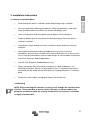
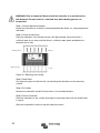
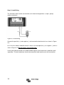
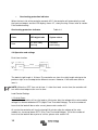
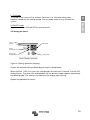
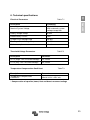
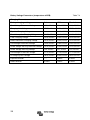
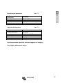
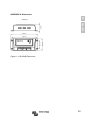
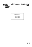
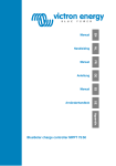
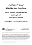
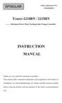
EN Manual Appendix BlueSolar Charge controller 12/24V-10A with timer Copyrights 2008 Victron Energy B.V. All Rights Reserved This publication or parts thereof may not be reproduced in any form, by any method, for any purpose. For conditions of use and permission to use this manual for publication in other than the English language, contact Victron Energy B.V. VICTRON ENERGY B.V. MAKES NO WARRANTY, EITHER EXPRESSED OR IMPLIED, INCLUDING BUT NOT LIMITED TO ANY IMPLIED WARRANTIES OF MERCHANTABILITY OR FITNESS FOR A PARTICULAR PURPOSE, REGARDING THESE VICTRON ENERGY PRODUCTS AND MAKES SUCH VICTRON ENERGY PRODUCTS AVAILABLE SOLELY ON AN “AS IS” BASIS. IN NO EVENT SHALL VICTRON ENERGY B.V. BE LIABLE TO ANYONE FOR SPECIAL, COLLATERAL, INCIDENTAL, OR CONSEQUENTIAL DAMAGES IN CONNECTION WITH OR ARISING OUT OF PURCHASE OR USE OF THESE VICTRON ENERGY PRODUCTS. THE SOLE AND EXCLUSIVE LIABILITY TO VICTRON ENERGY B.V., REGARDLESS OF THE FORM OF ACTION, SHALL NOT EXCEED THE PURCHASE PRICE OF THE VICTRON ENERGY PRODUCTS DESCRIBED HERE IN. Victron Energy B.V. reserves the right to revise and improve its products as it sees fit. This publication describes the state of this product at the time of its publication and may not reflect the product at all times in the future 2 Installation and Operation Manual EN Appendix Specification Summary Nominal system voltage: 12 / 24VDC* Maximum PV input voltage: 50V Nominal charge / discharge current 10A * The controller will recognize the system rated voltage when start up. If the battery voltage is lower than 18V, it will recognize the system as 12V. If the battery voltage is greater than 18V, it will recognize the system as 24V. 3 Contents 1 Important Safety Information ....................................................5 2 General Information .................................................................6 2.1 Product Overview .................................................................6 2.2 Product Features ..................................................................7 3 Installation Instructions ............................................................9 3.1 General Installation Notes .....................................................9 3.2 Mounting...............................................................................9 3.3 Wiring ................................................................................. 11 4 Operation............................................................................... 15 4.1 PWM Technology ............................................................... 15 4.2 Battery Charging Information .............................................. 15 4.3 LED Indicators .................................................................... 16 4.4 Operation and settings ........................................................ 18 4.5 Setting the timers ................................................................ 19 5 Protections, Troubleshooting and Maintenance...................... 22 5.1 Protection ........................................................................... 22 5.2 Troubleshooting .................................................................. 23 5.3 Maintenance ....................................................................... 24 6 Technical Specifications ........................................................ 25 Appendix A: Dimensions ........................................................... 29 4 1. Important Safety Information EN This manual contains important safety, installation and operating instructions. Appendix The following symbols are used throughout this manual to indicate potentially dangerous conditions or mark important safety instructions, please take care when meeting these symbols. WARNING: Indicates a potentially dangerous condition. Use extreme caution when performing this task. CAUTION: Indicates a critical procedure for safe and proper operation of the controller. NOTE: Indicates a procedure or function that is important for the safe and proper operation of the controller. General Safety Information • Read all of the instructions and cautions in the manual before beginning installation. • There are no user serviceable parts inside the controller. Do not disassemble or attempt to repair it. • Install external fuses/breakers as required. • Disconnect the solar module and fuse/breakers near to battery before installing or adjusting the controller. • Do not allow water to enter the controller. • Confirm that power connections are tightened to avoid excessive heating from loose connection. 5 2. General Information 2.1 Product Overview • 12/24V automatic recognition • Efficient Series PWM charging, increases battery lifetime and improves solar system performance. • Uses MOSFET as electronic switch, without any mechanical switch • Automatic day/night recognition. • Digital LED menu. • Intelligent timer function with 1-15 hours option. • Unique dual timer function, enhances the flexibility of street light system. • Gel, Sealed and Flooded battery type option. • Temperature compensated charging and discharging. • Electronic protection: overheating, over charging, over discharging, overload, and short circuit. • Reverse current protection. The controller is for off-grid solar systems, especially solar light systems, and protects the battery from being over charged by the solar module and over discharged by the loads. The charging process has been optimized for long battery life and improved system performance. The comprehensive self-diagnostics and electronic protection functions can prevent damage from installation mistakes or system faults. Though the controller is easy to operate and use, please take your time to read this manual and become familiar with it. This will help you make full use of all the functions and improve your solar PV system. 6 2.2 Product Features EN Appendix Figure 2-1 Land Star characteristics 1 –Temperature Sensor Measures ambient temperature. Used for temperature compensated charging and discharging. 2 – Charging status LED indicator A LED indicator that shows charging status and also indicates when a solar input fault condition exists 3 – Battery status LED indicator A LED indicator that shows battery status 4 – Battery type setting indicator The indicator will be on when the battery type is selected. 5 – Timer 2 setting indicator The indicator will be on when setting timer 2. 6 – Timer 1 setting indicator The indicator will be on when setting timer 1. 7 –LED digital display Displays the load mode and status 8 –Setting button (in manual mode used for load ON/OFF) To set load mode and to select battery type. 7 9 –Solar Module Terminals Connect solar modules. 10 –Battery Terminals Connect batteries. 11 –Load Terminals Connect loads. 8 3. Installation Instructions EN 3.1 General Installation Notes Appendix • Read through the entire installation section before beginning installation. • Be very careful when working with batteries. Wear eye protection. Have fresh water available to wash and clean any contact with battery acid. • Uses insulated tools and avoid placing metal objects near the batteries. • Explosive battery gasses may be present during charging. Be certain there is sufficient ventilation. • Avoid direct sunlight and do not install in locations where water can enter the controller. • Loose power connections and/or corroded wires may result in resistive connections that melt wire insulation, burn surrounding materials, or even cause fire. Ensure tight connections and use cable clamps to secure cables and prevent them from swaying in mobile applications. • Use with Gel, Sealed or Flooded batteries only. • Battery connection may be wired to one battery or a bank of batteries. The following instructions refer to a singular battery, but it is implied that the battery connection can be made to either one battery or a group of batteries in a battery bank. • Select the system cables according to 3A/mm2 current density. 3.2 Mounting NOTE: When mounting the controller, ensure free air through the controller heat sink fins. There should be at least 6 inches (150 mm) of clearance above and below the controller to allow for cooling. If mounted in an enclosure, ventilation is highly recommended. 9 WARNING: Risk of explosion! Never install the controller in a sealed enclose with batteries! Do not install in a confined area where battery gasses can accumulate. Step 1: Choose Mounting Location Locate the controller on a vertical surface protected from direct sun, high temperature, and water. Step 2: Check for clearance Place the controller in the location where it will be mounted. Verify that there is sufficient room to run wires and that there is sufficient room above and below the controller for air flow. 150mm(5.9inches) 150mm(5.9inches) Warm air Cool air Figure 3-1 Mounting and cooling Step 3: Mark Holes Use a pencil or pen to mark the four (4) mounting hole locations on the mounting surface. Step 4: Drill Holes Remove the controller and drill 4.5mm holes in the marked locations. Step 5: Secure Controller Place the controller on the surface and align the mounting holes with the drilled holes in step 4. Secure the controller in place using the mounting screws. 10 3.3 Wiring EN NOTE: Please follow the recommended connection order for maximum safety during installation. Appendix NOTE: The controller is a common positive ground controller. CAUTION: Don’t connect loads with surge power exceeding the ratings of the controller. CAUTION: For mobile applications, be sure to secure all wiring. Use cable clamps to prevent cables from swaying when the vehicle is in motion. Unsecured cables create loose and resistive connections which may lead to excessive heating and/or fire. Step1: Battery Wiring WARNING: Risk of explosion or fire! Never short circuit battery positive (+) and negative (-). Fuse 150mm(5.9inches) MAX Battery Figure 3-2 Battery connecting Before connecting the battery, make sure that battery voltage is greater than 6V so as to start up the controller. If the system is 24V, make sure battery voltage is not less than 18V. System voltage can only be automatically recognized when the controller starts up for the first time. When installing a fuse, make sure that the distance between the fuse holder and the positive terminal of battery is at most 150mm. Do not insert a fuse at this time. 11 Step 2: Load Wiring The controller loads can be connected to such electrical equipments as lights, pumps, motors and others. Fuse Load Figure 3-3 Load Wiring Connect the positive (+) and negative (-) to the controller load terminals as shown in Figure 3-3. An in-line fuse holder should be wired in series in the load positive (+) or negative (-) wire as show in Figure 3-3. Do not insert a fuse at this time. If wiring the load connection to a load distribution panel, each load circuit should be fused separately. The total load draw should not exceed the load rated current of the controller. 12 Step 3: Solar wiring EN Appendix WARNING: Risk of electric shock! Exercise caution when handling solar wiring. The solar module(s) high voltage output can cause severe shock or injury. Cover the solar module(s) from the sun before installing solar wiring. The controller can accept 12V or 24V nominal off-grid solar module(s). Solar Module Figure 3-4 Solar wiring Step 4: Confirm Wiring Double-check the wiring. Confirm correct polarity at each connection. Verify that all six terminals are tightened. Solar Module Load Fuse Fuse 150mm(5.9inches) MAX Battery Figure 3-5 System wiring review 13 Step 5: Install Fuse Install a suitable fuse in each fuse holder in the following order: 1. Battery circuit 2. Load circuit Step 6: Confirm power on When battery power is applied and the controller starts up, the battery LED indicator will be green. If the controller doesn't start up, or the battery status LED error is on, please refer to section 5 for troubleshooting. 14 4. Operation EN 4.1 PWM Technology (Series Pulse Width Modulation) The controller features advanced series pulse width modulation. Appendix 4.2 Battery Charging Information Figure 4-1 PWM Charging mode • Bulk Charge In this stage, the battery voltage has not yet reached boost voltage and 100% of available solar power is used to charge the battery. • Boost/absorption Charge When the battery has been recharged to the Boost/absorption voltage setpoint, constant-voltage regulation is used to prevent heating and excessive battery gassing. The Boost/absorption time is 120 minutes • Float Charge After the battery is fully charged in the Boost/absorption voltage stage, the controller reduces the battery voltage to the Float voltage set point. The purpose of Float stage is to offset the power consumption caused by self consumption and small loads in the whole system, while maintaining full battery storage capacity. In Float stage, loads can continue to draw power from the battery. In the event that the system load(s) exceed the solar charge current, the controller will no longer be able to maintain the battery at the Float setpoint. Should the battery voltage drop below the Boost setpoint, the controller will exit Float stage and return to Bulk charge. 15 • Equalize Charge WARNING: Risk of explosion! Equalizing a flooded battery can produce explosive gases, good ventilation of the battery box is therefore necessary. NOTE: Equipment damage! Equalization may increase battery voltage to a level that is damaging to sensitive DC loads. Ensure that the allowable input voltage of the loads is greater than the equalize charging set point voltage. NOTE: Equipment damage! Over-charging and excessive gassing may damage the battery plates and activate material. Excessive equalizing charge may cause damage. Please carefully review the specific requirements of the battery used in the system. Certain types of batteries benefit from periodic equalizing charge, which will stir the electrolyte and balance battery voltage. Only if the battery has been over discharged, the solar controller will automatically turn to equalize charging, and the equalize stage will remain on during 120 minutes. 4.3 LED Indicators Charging Status LED indicator Battery Status LED indicator Figure 4-2 LED indicators • Charging status indicator GREEN ON whenever sunlight is available for battery charging, GREEN FAST FLASHING in case of system over voltage. Please refer to section 5 for troubleshooting. 16 Charging Status LED indicator Table 4-1 Charging Status Green On Solid Charging Green Fast Flashing Over voltage • Appendix Indicator EN Color Battery status indicator GREEN ON when battery voltage in normal range GREEN SLOWLY FLASHING when battery full ORANGE ON in case of battery under voltage RED ON when the battery is over discharged Please refer to section 5 for troubleshooting. • Battery status LED indicator Table 4-2 Color Indicator Battery Status Green On solid Normal Green Slowly Flashing Full Orange On solid Under voltage Red On solid Over discharged • Load status indicator When the load current is 1.25 times rated current for 60 seconds, or the load current is 1.5 times rated current for 5 seconds (overload); or load current is more than 3.5 times rated current (Short Circuit), the LED display shows “L”, slowly flashing. Please refer to section 5 for troubleshooting. • Load status LED indicator Table 4-3 Color LED digital tube Load status Red “L” with slowly flashing Overload or short circuit 17 • Overheating protection indicator When the heat sink of the controller exceeds 85°C, the controller will automatically cut off the input and output, and the LED display shows “H”, slowly flashing. Please refer to section 5 for troubleshooting. Overheating protection indicator Table 4-4 Color LED digital tube System status Red “H” with slowly flashing Controller overheating 4.4 Operation and settings Dual timer function Light ON Light OFF Timer 2 Timer 1 Number of hours Sunset Midnight Number of hours Sunrise The default night length is 10 hours.The controller can learn the night length refering to the previous night so as to adapt to the different seasons. However, it will take some time to learn it. NOTE: When the “OFF” time set at timer 1 is later than local sunrise time, the controller will turn off the load output at the sunrise time. Load Control Settings 1. Dusk to Dawn At sunset the controller will turn the load on 10 minutes after the voltage of the solar module voltage has decreased below NTTV (Night Time Threshold Voltage). To set the number of hours that the load will be on after sunset, please refer section 4.5. At sunrise the controller will turn the load off 10 minutes after the voltage of the solar module has increased above DTTV (Day Time Threshold Voltage). To set the number of hours that the load will be on prior to sunrise, please refer section 4.5. 18 EN 2. Test mode This mode is the same as Dusk to Dawn. But there is no 10 minutes delay when controller recognizes the starting voltage. The test mode makes it easy to check the system. Appendix 3. ON/OFF mode This mode is to turn ON and OFF the load manually. 4.5 Setting the timers Timer 1 Setting indicator LED display Timer 2 Setting indicator Battery type Setting Indicator Setting button Figure 4-3 Setting operation indicating Choose the required setting indicator by pressing the setting button. When the timer 1 LED is on, press the setting button for more than 5 seconds, until the LED display flashes. Then press the setting button until the desired number appears according to the following table. The setting is finished when the display stops flashing. Repeat the procedure for timer 2. 19 Load work mode Table 4-5 Timer 1 LED display No. Enable n Dusk to Dawn, Load will be on all night 0 Load will be on for 1 hour after ten minutes delay since sunset 1 Load will be on for 2 hours after ten minutes delay since sunset 2 Load will be on for 3 hours after ten minutes delay since sunset 3 Load will be on for 4 hours after ten minutes delay since sunset 4 Load will be on for 5 hours after ten minutes delay since sunset 5 Load will be on for 6 hours after ten minutes delay since sunset 6 Load will be on for 7 hours after ten minutes delay since sunset 7 Load will be on for 8 hours after ten minutes delay since sunset 8 Load will be on for 9 hours after ten minutes delay since sunset 9 Load will be on for 10 hours after ten minutes delay since sunset 10 Load will be on for 11 hours after ten minutes delay since sunset 11 Load will be on for 12 hours after ten minutes delay since sunset 12 Load will be on for 13 hours after ten minutes delay since sunset 13 Load will be on for 14 hours after ten minutes delay since sunset 14 Load will be on for 15 hours after ten minutes delay since sunset 15 Test mode 16 ON/OFF mode 17 20 Load work mode Table 4-6 Enable n Load will be on for 1 hour before sunrise 1 Load will be on for 2 hours before sunrise 2 Load will be on for 3 hours before sunrise 3 Load will be on for 4 hours before sunrise 4 Load will be on for 5 hours before sunrise 5 Load will be on for 6 hours before sunrise 6 Load will be on for 7 hours before sunrise 7 Load will be on for 8 hours before sunrise 8 Load will be on for 9 hours before sunrise 9 Load will be on for 10 hours before sunrise 10 Load will be on for 11 hours before sunrise 11 Load will be on for 12 hours before sunrise 12 Load will be on for 13hours before sunrise 13 Load will be on for 14 hours before sunrise 14 Load will be on for 15 hours before sunrise 15 Appendix LED display No. EN Timer 2 NOTE: Timer 2 is disabled when timer 1 is set to Dusk to Dawn( 0), Test mode (16) or ON/OFF mode (17). • Battery Type Setting When the battery type setting LED is on, press the setting button for more than 5 seconds, until the LED display flashes. Then press the setting button until the desired number appears according to the following table. The setting is finished when the display stops flashing. Battery type setting Battery type Table 4-7 LED display Sealed lead acid battery 1 Gel battery 2 Flooded battery 3 21 5. Protection, Troubleshooting and Maintenance 5.1 Protection 22 • PV Array Short Circuit If a PV array short circuit occurs, clear it to resume normal operation. • Load output overload If the load current exceeds the maximum load current rating, the controller will disconnect the load. The greater the overload, the faster the load will be disconnected. A small overload could take a few minutes to disconnect. Disconnect due to overload must be cleared by pressing the setting button. • Load output short circuit After one automatic load reconnect attempt, the fault must be cleared by pressing the setting button. • PV reverse polarity Correct the wiring error to resume normal operation. • Battery Reverse Polarity Correct the wiring error to resume normal operation. • Damaged temperature sensor If the temperature sensor is short-circuited or damaged, the controller will be charging or discharging at the default temperature 25°C. • Overheating protection If the temperature of the controller heat sink exceeds 85°C, the controller will cutoff the input and output. • High Voltage Transients The battery is protected against high voltage transients. In lightning prone areas, additional external suppression is recommended. 5.2 Troubleshooting EN Trouble Shooting Table 5-1 Possible reasons Troubleshooting Charging LED indicator off during daytime when sunshine falls on PV modules properly. PV array disconnected Check that PV and battery wire connections are correct and tight. Green charging LED indicator fast flashing Battery voltage higher than over voltage disconnect voltage (OVD) Check battery voltage. Disconnect the solar module Battery LED indicators are orange Battery under voltage Battery LED indicators RED color and loads not working. Battery over discharged LED display shows “L”, slowly flashing Over load or short circuit LED display shows “H”, slowly flashing Over temperature Appendix Faults Load output is normal, charging LED indicator will return to green automatically when fully charged. The controller did cut off the load output automatically. The LED indicator will return to green after fully charging the battery. Overload: please reduce the load and press the button once, the controller will resume normal operation after 3s. Short circuit: when the first short-circuit occurs, the controller will automatically resume normal operation after 10s; when a second short-circuit occurs, press the button, the controller will resume normal operation after 3s. When heat sink of the controller exceeds 85°C, the controller will automatically cut input and output circuit. When the temperaturehas decreased below 75°C, the controller will resume to work 23 NOTE: If all LED’s are off. Measure battery voltage with multimeter. At least 6V is needed to start the controller. NOTE: No charging status LED indicator with normal connection. Measure the input voltage of solar module, the input voltage must be higher than battery voltage! 5.3 Maintenance The following inspections and maintenance tasks are recommended at least two times per year for best controller performance. 24 • Check that the controller is securely mounted in a clean and dry environment. • Check that the air flow and ventilation around the controller is not blocked. Clear all dirt or fragments on the heat sink. • Check the wiring to make sure insulation is not damaged by sunlight, frictional wear, insects or rats etc. Replace if necessary. • Tighten all the terminals. Inspect for loose, broken, or burnt wire connections. • Pay attention to any troubleshooting or error indication .Take necessary corrective action. 6. Technical specifications EN Electrical Parameters Table 7-1 Parameter Nominal System Voltage 12 / 24VDC With automatic system voltage recognition Battery Voltage Range 6-36V Rated Battery Current 10A Charge Circuit Voltage Drop ≤0.26V Discharge Circuit Voltage Drop ≤0.15V Self-consumption ≤6mA Threshold Voltage Parameters Appendix Description Table7-2 Description Parameter NTTV (Night Time Threshold Voltage) 5V; x2/24V DTTV (Day Time Threshold Voltage) 6V; x2/24V Temperature Compensation Coefficient Table7-3 Description Parameter Temperature Compensation Coefficient* -30mV/℃/12V (25℃ ref) * Compensation of equalize, boost, float and boost reconnect voltage 25 Battery Voltage Parameters (temperature at 25℃ ℃) Table 7-4 Charging Parameters Battery charging setting Gel AGM Over Voltage Disconnect Voltage 16V; x2/24V 16V; x2/24V 16V; x2/24V Charging Limit Voltage 15.5V;x2/24V 15.5V;x2/24V 15.5V;x2/24V Equalize Charging Voltage ----- 14.6V;x2/24V 14.8V;x2/24V Boost/absorption Charging Voltage 14.2V;x2/24V 14.4V;x2/24V 14.6V;x2/24V Float Charging Voltage 13.8V;x2/24V 13.8V;x2/24V 13.8V;x2/24V Boost Reconnect Charging Voltage 13.2V;x2/24V 13.2V;x2/24V 13.2V;x2/24V Low Voltage Reconnect Voltage 12.6V;x2/24V 12.6V;x2/24V 12.6V;x2/24V Under voltage warning reconnect voltage 12.2V;x2/24V 12.2V;x2/24V 12.2V;x2/24V Under Voltage Warning Voltage 12V; x2/24V 12V; x2/24V 12V; x2/24V Low Voltage Disconnect Voltage 11.1V;x2/24V 11.1V;x2/24V 11.1V;x2/24V Discharging Limit Voltage 10.8V;x2/24V 10.8V;x2/24V 10.8V;x2/24V Equalize duration ----- 2 hours 2 hours Boost duration 2 hours 2 hours 2 hours 26 Flooded Table 7-5 Parameter -35℃ to +55℃ -35℃to +80℃ 10%-90% non condensing IP30 Mechanical parameters Mechanical Parameter Overall dimensions Mounting dimensions Mounting hole size Terminals Net weight Appendix Environmental parameters Operating temperature Storage temperature Humidity Enclosure EN Environmental parameters Table 7-6 Parameter 140(5.51)x65(2.56)x34(1.34) mm/inches 130(5.12) x 45(1.77) mm/inches Φ4.5 6mm2 0.15kg Final interpretation right of the manual belongs to our company. Any changes without prior notice! 27 28 APPENDIX A: Dimensions EN mm(inches) 34(1.34) Appendix 140(5.51) 65(2.56) 45(1.77) 130(5.12) Figure 1-1 LS1024R Dimensions 29 Victron Energy Blue Power Distributor: Serial number: Version : 00 Date : 20 February 2013 Victron Energy B.V. De Paal 35 | 1351 JG Almere PO Box 50016 | 1305 AA Almere | The Netherlands General phone Customer support desk Fax : +31 (0)36 535 97 00 : +31 (0)36 535 97 03 : +31 (0)36 535 97 40 E-mail : [email protected] www.victronenergy.com