1
Agilent J2126/7A
Transmission Test Sets
Quick Reference
Guide
QRG_SONET1.book Page 16 Monday, June 10, 2002 11:39 AM
Agilent J2126/7A
Transmission
Test Sets
Quick Reference
Guide
Agilent Technologies
Notices
© 2002 Agilent Technologies UK Limited
No part of this manual may be reproduced
in any form or by any means (including
electronic storage and retrieval or translation into a foreign language) without prior
agreement and written consent from Agilent Technologies UK Limited as governed
by international copyright laws.
Manual Part Number
J7280-90011
Edition
First edition, September 2002
Printed in UK
Agilent Technologies UK Limited
Transmission & Transport Test Operation
South Queensferry, West Lothian,
Scotland EH30 9TG
Warranty
The material contained in this document
is provided “as is,” and is subject to
being changed, without notice, in future
editions. Further, to the maximum extent
permitted by applicable law, Agilent disclaims all warranties, either express or
implied, with regard to this manual and
any information contained herein, including but not limited to the implied warranties of merchantability and fitness for a
particular purpose. Agilent shall not be
liable for errors or for incidental or consequential damages in connection with
the furnishing, use, or performance of this
document or of any information contained
herein. Should Agilent and the user have
a separate written agreement with warranty terms covering the material in this
document that conflict with these terms,
the warranty terms in the separate agreement shall control.
Technology Licenses
The hardware and/or software described
in this document are furnished under a
license and may be used or copied only in
accordance with the terms of such license.
Restricted Rights Legend
If software is for use in the performance of
a U.S. Government prime contract or subcontract, Software is delivered and
licensed as “Commercial computer software” as defined in DFAR 252.227-7014
(June 1995), or as a “commercial item” as
defined in FAR 2.101(a) or as “Restricted
computer software” as defined in FAR
52.227-19 (June 1987) or any equivalent
agency regulation or contract clause. Use,
duplication or disclosure of Software is
subject to Agilent Technologies’ standard
commercial license terms, and non-DOD
Departments and Agencies of the U.S.
Government will receive no greater than
Restricted Rights as defined in FAR
52.227-19(c)(1-2) (June 1987). U.S. Government users will receive no greater than
Limited Rights as defined in FAR 52.227-14
(June 1987) or DFAR 252.227-7015 (b)(2)
(November 1995), as applicable in any
technical data.
2
In This Quick Reference Guide…
This guide contains information on:
• The conventions used within this guide.
• A Getting Started chapter for new users.
• An introduction to using the Graphical User Interface (GUI),
including information on the display windows, the menus
and basic GUI operations.
• An introduction to using Online Help, including information
on how to add and use your own help files.
• An introduction to using and selecting Multiple Instruments.
• Using Smart Test and SignalWizard, the quick and easy way
to set up and use the instrument.
• Some tips on avoiding problems when making measurements.
• Quick reference tables listing the front panel settings to rapidly select major instrument functions.
CAU T ION
WARN IN G
A CAUTION notice denotes a hazard. It calls attention to an
operating procedure, practice, or the like that, if not correctly performed or adhered to, could result in damage to
the product or loss of important data. Do not proceed
beyond a CAUTION notice until the indicated conditions
are fully understood and met.
A WARNING notice denotes a hazard. It calls attention to
an operating procedure, practice, or the like that, if not
correctly performed or adhered to, could result in
personal injury or death. Do not proceed beyond a
WARNING notice until the indicated conditions are fully
understood and met.
Transmission Test Set Quick Reference Guide
3
Conventions Used in This Guide…
• Front panel buttons appear in bold within angled brackets.
For example, press <Menu>.
• When buttons are connected by a plus (+) sign, for example,
<2> + <4>, press the listed buttons in sequence.
• Menu items appear in bold. The greater than (>) symbol
separates each menu level. For example, `Test Functions >
Errors and Alarms’ indicates that you should choose
`Errors and Alarms' from the `Test Functions’ main menu.
• Field items and drop down list entries appear in bold. For
example, `select Signal Rate field and choose OC-3 from
the drop-down list’.
• This Guide applies to both SONET and SDH network standards. Where there is a difference in the terminology used
between these two standards, the SONET version is given
first.
4
Transmission Test Set Quick Reference Guide
Contents
1
Product Description
Introduction 10
Option Guide 12
Other Options 15
Accessories 15
2
Getting Started
Front Panel Tour 18
Function Controls 18
Navigation Controls 19
Keypad 20
Print Control 22
Status and Alarm LEDs 23
Top Panel Tour 24
Optical Out Ports 24
Optical In Ports 25
Clock Ports 26
DCC Port 28
Electrical Test Ports 29
Ethernet Ports 30
Left Side Panel Tour 31
Right Side Panel Tour 32
Using a Mouse and Keyboard
34
Selecting SONET or SDH Operation 35
3
Using the Graphical User Interface
Display Windows 38
Menus 40
Basic User Interface Operations 41
Transmission Test Set Quick Reference Guide
5
4
Using Online Help
Which Keys Do I Press? 48
Context-Sensitive Help 49
Accessing the Index 49
Adding and Using Your Own Help Files 49
Accessing Your Own Help Files 49
Create Your Own Help Files 50
Adding/Updating Your Own Help Files 52
Copy Your Own Help Files to Disk 53
Delete Your Own Help Files 54
5
Using Multiple Instruments
Feature Summary 56
6
Using Smart Test and SignalWizard
Shortcuts to Results, Measurements and Stored
Settings 60
Resetting Instrument to Default Settings 60
Using the SignalWizard Test Feature 61
Understanding SignalWizard Overview Window 63
Monitoring Path Trace Messages 66
In-Service Testing 68
Out-of-Service Testing 69
7
Hints and Tips
Avoiding Problems When Making Measurements 72
Avoiding Optical Receiver Overload 73
Cleaning Optical Connectors 74
Front Panel Soft Recovery (Cold Start) 75
Performing a Cold Start 75
6
Transmission Test Set Quick Reference Guide
8
Quick Reference Tables
Smart Test 78
Print Control 79
Multiple Instruments 79
SONET/SDH Transmitter Functions 80
SONET/SDH Receiver Functions 82
SONET/SDH Overhead Setup 84
SONET/SDH Overhead Monitor 86
SONET/SDH Results 88
SONET/SDH Test Functions 90
Ethernet Functions 91
System Functions 92
System Functions – Measurement Logging 93
System Functions – File Manager 94
Transmission Test Set Quick Reference Guide
7
8
Transmission Test Set Quick Reference Guide
Agilent J2126/7A Transmission Test Set Quick
Reference Guide
1
Product Description
Introduction 10
Option Guide 12
Alternative Optical Connectors (available
accessories) 14
Ethernet Capability 11
Other Options 15
Accessories 15
Agilent Technologies
9
1
Product Description
Introduction
The instrument provides all the test capability you need to
install and verify the performance of today’s high-capacity
transmission systems and networks in one portable package.
In addition, there is an Ethernet module that can fully test the
data capabilities of the new generation of multi-service network elements.
SONET/SDH Capability
• Global test coverage (SONET, SDH, PDH and T-Carrier).
• Full integrated all-rate testing:
• 52 Mb/s to 10 Gb/s optical.
• 52/155 Mb/s; DS1/3; 2/8/34/140 Mb/s electrical.
• Full range of standard and concatenated mappings.
• All standard error and alarm measurements, plus:
• optical power, electrical level, pulse mask, frequency.
• service disruption time, pointer movements, delay.
• Simultaneous all-channel testing (up to 192 STSs/AUs).
• Intrusive and non-intrusive Thru-mode.
• Comprehensive SONET/SDH overhead testing.
• Electrical interfaces
• (DS1/3; 2/8/34/140 Mb/s; 52/155 Mb/s)
10
Transmission Test Set Quick Reference Guide
1
Product Description
• VT/TU payload testing
• DS1/3 and 2/34/140 Mb/s service mappings
• DSn and PDH (En) testing
• Pulse mask testing (up to 52 Mb/s electrical)
• Service disruption measurement
• Round trip delay measurement
• Electrical level measurement
• Graphical error and alarm result displays
• G.821, M2100, M2101, M2101.1, M2110, M.2120 performance analysis
• Fast access to key measurement tasks using Smart Test.
• Line and payload frequency offset.
• Transmit and Receive can be independently configured.
• Broad range of graphical results tools.
• Comprehensive online help facilities:
• Online User manual.
• Context-sensitive help for each control field.
• Ability to add your own help documents.
Ethernet Capability
• Test data services at Layer 1 and Layer 2
• Multi-port testing - 8x10/100 Mb/s and 2x1 Gigabit Ethernet
• Simultaneous operation of all ports
• Simultaneous SONET/SDH and Ethernet operation
• Extremely simple to set-up and operate
• Hot-swap GBIC modules for wavelength choice
• Automated RFC 2544 benchmark testing
• Full rate traffic generation and reception
• Can be used for end-to-end or loopback testing
• Unique “Loopthru” mode allows loopback testing even at
Layer 2
Transmission Test Set Quick Reference Guide
11
1
Product Description
• Measure the “Transmission” elements of Ethernet:
• Throughput
• Latency
• Frame Loss
• Errors
• User selectable full/restricted/fixed auto negotiation
• User selectable VLAN/priority tagging and flow control
• Frame capture facility
• Comprehensive online help facilities:
• Online User manual
• Context-sensitive help for each control field
• Ability to add your own help documents
Option Guide
There are three mainframes:
• J2126A - 3-slot chassis.
• J2127A - 4-slot chassis.
• J2127A - 6-slot extended chassis.
Mainframe and Potential Test Rate Capability
Mainframe
Optical Test Interfaces
Frequency Range
J2126A
(see Note 1)
OC-1, OC-3, OC-12, OC-48
STM-0, STM-1, STM-4, STM-16
52 Mb/s to 2.5 Gb/s
J2127A
(see Notes 1, 2
and 3)
52 Mb/s to 10 Gb/s
OC-1, OC-3, OC-12, OC-48,
OC-192
STM-0, STM-1, STM-4, STM-16,
STM-64
1. With option 103 fitted, maximum line rate restricted to OC-12/STM-4.
2. Can be configured with maximum line rate of OC-48/STM-16 and later
upgraded to OC-192/STM-64.
3. Can have a 4-slot chassis or extended (6-slot) chassis.
12
Transmission Test Set Quick Reference Guide
Product Description
1
Optical Interfaces
Optical interfaces
operating up to
2.5 Gb/s
Optical interfaces
operating up to
10 Gb/s
Tx Optical
Wavelength
Option
1310 nm
100
1550 nm
101
1310/1550 nm
102
1550 nm
111(HS*), 121 (SR**)
1310 nm
120 (SR**)
* HS - High Rx sensitivity optics.
** SR - Short reach optics.
Optical Connectors (product options)
Connector
Option
FC/PC Adapters fitted on all optical interfaces
190
SC Adapters fitted on all optical interfaces
191
ST Adapters fitted on all optical interfaces
192
Transmission Test Set Quick Reference Guide
13
1
Product Description
Alternative Optical Connectors (available
accessories)
Alternative optical connectors are available for your product,
order the appropriate J7283A (FC/PC), J7284A (SC) or
J7285A (ST) accessory (connector). The number of connectors
required for your product is shown below.
J7283A
(FC/PC)
J7284A
(SC)
J7285A
(ST)
J2126A with
option 100/101
2
2
2
J2126A with
option 102
3
3
3
J2127A* with
option 100/101 and
111/120/121
5
5
5
J2127A* with
option 102 and
111/120/121
6
6
6
* Can have a 4-slot chassis or extended (6-slot) chassis.
Ethernet Options
Option
14
Ethernet testing (8 x 10/100 Mb/s; 2 x 1 Gb/s)
323
1000Base-SX (850 nm) GBIC modules (two)
325
1000Base-LX (1310 nm) GBIC modules (two)
326
Transmission Test Set Quick Reference Guide
Product Description
1
Other Options
Certificate of Calibration
Option UK6:
Calibration certificate with test data.
Warranty and Service Plans
Terms and conditions of the applicable warranty for this product are contained in the sales and related documentation supplied separately.
Please contact your nearest Agilent Technologies Sales Office
for further information on warranty and extended warranty
options.
For access to Agilent Product information and sales/service
contacts, please visit:
http://www.agilent.com
Accessories
Additional Documentation
J7280A:
Full set of printed manuals:
User Guide
Quick Reference Guide
Remote Control Manual
Installation and Verification Manual
Carrying Cases
J7286A:
Hard transit case (for J2126A).
J7287A:
Hard transit case (for J2127A).
J7288A:
Soft carrying case (for J2126/7A).
J7289A:
sis).
Hard transit case (for J2127A 6-slot extended chas-
J7290A: Soft carrying case (for J2127A 6-slot extended
chassis).
Transmission Test Set Quick Reference Guide
15
1
Product Description
Optical Adapters and Cables
16
J7283A:
FC/PC optical connector (exchangeable)
J7284A:
SC optical connector (exchangeable)
J7285A:
ST optical connector (exchangeable)
J7281A:
DCC port converter cable: 9-pin miniature D-type to
37-pin D-type (RS-449, female)
Transmission Test Set Quick Reference Guide
Agilent J2126/7A Transmission Test Set Quick
Reference Guide
2
Getting Started
Front Panel Tour 18
Top Panel Tour 24
Left Side Panel Tour 31
Right Side Panel Tour 32
Using a Mouse and Keyboard 34
Selecting SONET or SDH Operation 35
This chapter guides you round the many features of the instrument. It also includes information on how to chose the network standard (SONET or SDH) for the instrument.
Agilent Technologies
17
2
Getting Started
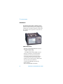
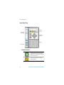
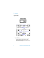
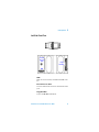
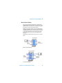
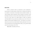
Front Panel Tour
Function
Controls
Status and
Alarm LEDs
Navigation
Controls
Keypad
Print Control
Function Controls
Press this button to start a new test period
or terminate the current test period. The
LED indicator above the button is on when a
test period is in progress.
Press this button to access the Agilent
Smart Test menu. Operates on the foreground instrument.
18
Transmission Test Set Quick Reference Guide
Getting Started
2
Press this button to add a single error to the
transmitted signal. The type of error added
is selected on the Test Functions > Errors
and Alarms page. Operates on the foreground instrument.
Press this when you need to refer to the
online help. Press it again to take you back
to the instrument display.
Navigation Controls
The <Arrow Navigation> buttons move the
focus up/down/left/right through menus,
drop-down lists and the instrument display.
Press <Select> to enter any selected menu
item or value you have entered into a field.
Press <Menu> to display the main menu
for the current application.
Press <Menu> again, or press <Cancel>,
to close the menu.
Press <Window> to change the focus
between the left and right windows.
<Cancel> will close any menu or drop
down list without making any changes.
Transmission Test Set Quick Reference Guide
19
2
Getting Started
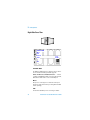
Keypad
The keypad provides quick text and numeric entry. Some keys
are also used for navigation in the online help system.
The operation of the keys depends on the mode of operation
for the current entry field.
Help
Function
Keys
Numeric
Entry
Text
Entry
Numeric Entry
In a numeric entry field, enter the number you want using the
keypad. Decimal, binary and hexadecimal entries are all made
directly from the keypad.
Special keys used in numeric entries:
Press <Minus> to enter a negative value, for example for a frequency offset of -99.9 ppm, press:
< - > + <9> + <9> + < . > + <9>
Press < X > for ‘don’t care’ entries.
Use this key to enter an exponent, for example for
an error rate of 9.9E-9 press:
<9> + < . > + <9> + <Exp> + < - > + <9>
To edit a number press the <Left Arrow> key for
backspace operation deleting preceding entry.
20
Transmission Test Set Quick Reference Guide
Getting Started
2
Text Entry
In a text entry field, for example when editing a trace message,
the keypad will be in text mode.
You enter text in the same way as you would enter text into a
cell phone. The keys are labelled “abc2ABC”, “def3DEF” and
so on. Press the key with the character you want: once for the
first character, twice (pressing the key quickly in succession)
for the second and so on.
To enter numbers or upper case letters quickly, use the <F/up
arrow> key to switch between lower case characters
(CapsOff), upper case (CapsOn) and number (Num). The current mode is displayed in the Status Line at the bottom right of
the screen.
Special keys used in text entries:
This key switches between upper and lower case
characters and numbers. The current mode, either
“Caps” or “Num” - is displayed at the bottom right
of the screen on the Status Line.
Press this key for these special characters:
space _ NUL LF CR
Press this key for these math symbols
-+/*=<>%^
Press this key for these miscellaneous symbols
@ # 0 $ \ & ~( ) [ ] { }
Press this key for these punctuation symbols
.?!,:;“‘‘
Transmission Test Set Quick Reference Guide
21
2
Getting Started
Help Function Keys
These keys are used for additional navigation when in Online
Help.
Home
Returns you to the Home page.
Back
Takes you back to the previous page.
Fwd
If you have used the <Back> key for navigating
then this key takes you forward to where you have
come from. Otherwise, pressing this key has no
effect.
Prev
Page
Scrolls up through the displayed page.
Next
Page
Scrolls down through the displayed page.
Print Control
Press <Print Control> to access the print control
page. Operates on the foreground instrument.
22
Transmission Test Set Quick Reference Guide
Getting Started
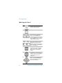
2
Status and Alarm LEDs
The Status LED indicators provide information about the status
of the instrument’s receiver. The Signal, Frame and Pattern
indicators are green if the signal is good, and red during an
alarm condition. Error indicator is off or red if error detected.
SIGNAL Green: Valid signal (level; data transitions)
detected at input. Red: No data transitions detected at
input or low optical/electrical power. Operates on the foreground instrument.
FRAME Green: Correct framing detected at all levels of the
received signal (on the line signal plus all levels down to
the selected test channel). Red: Frame alignment lost at
one or more levels of the received signal. Operates on the
foreground instrument.
PATTERN Green: Correct detection of expected test pattern. Red: Expected test pattern not received. Operates on
the foreground instrument.
ERRORS Red: An error has been detected in the received
signal. The indicator remains red for 100 ms, then returns to
off. Operates on the foreground instrument.
SONET/SDH: Indicates that at least one SONET or SDH
alarm is present. Operates on the foreground instrument.
DSn: Indicates that at least one ANSI DS1, DS2 or DS3
alarm is present. Operates on the foreground instrument.
PDH: Indicates that at least one ETSI E1, E2, E3 or E4 alarm
is present. Operates on the foreground instrument.
Multiple Instruments: Indicates that an error or alarm has
been detected by a background instrument.
History: Press <Show More> to view the alarm history.
<Show More> provides access to the detailed alarm information (both current status and history). If an alarm has
occurred during the current test period, the History indicator will be on. Operates on the foreground instrument.
Press <Reset> to reset the Alarm History data. The History
LED will go off. If an alarm condition is present during the
reset, then the LEDs associated with that alarm will remain
on after the reset. Resetting of the history data also occurs
when you start a new test period. Operates on the foreground instrument.
Transmission Test Set Quick Reference Guide
23
2
Getting Started
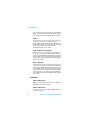
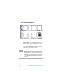
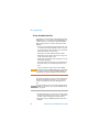
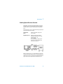
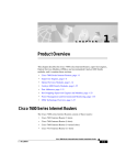
Top Panel Tour
Electrical Test Ports
DCC
Ethernet Ports
TX Eye Clock 10 Gb/s
Optical Out Ports
Optical In Ports
Clock Ports
Optical Out Ports
Provides SONET optical signals OC-1, OC-3, OC-12, OC-48,
OC-192, and SDH optical signals STM-0, STM-1, STM-4,
STM-16, STM-64 at wavelength 1310 and 1550 nm, depending
on instrument model and options.
24
Transmission Test Set Quick Reference Guide
Getting Started
2
52 Mb/s - 2.5 Gb/s 1310 nm
Selectable optical connector (see “Optical Connectors (product options)” on page 13) for a 52 Mb/s to 2.5 Gb/s optical
output. Nominal wavelength is 1310 nm. Power output is -5 to
+0 dBm.
52 Mb/s - 2.5 Gb/s 1550 nm
Selectable optical connector (see “Optical Connectors (product options)” on page 13) for a 52 Mb/s to 2.5 Gb/s optical
output. Nominal wavelength is 1550 nm. Power output is -2 to
+3 dBm.
10 Gb/s, 1550 nm
Selectable optical connector (see “Optical Connectors (product options)” on page 13) for a 10 Gb/s optical output. Nominal wavelength is 1550 nm. Power output is -1 to +1 dBm.
10 Gb/s, 1550 nm (SR)
Selectable optical connector (see “Optical Connectors (product options)” on page 13) for a 10 Gb/s optical output. Nominal wavelength is 1550 nm. Power output is -5 to -1 dBm.
10 Gb/s, 1310 nm (SR)
Selectable optical connector (see “Optical Connectors (product options)” on page 13) for a 10 Gb/s optical output. Nominal wavelength is 1310 nm. Power output is -6 to -1 dBm.
Optical In Ports
Accepts SONET OC-1, OC-3, OC-12, OC-48 and OC-192 and
SDH STM-0, STM-1, STM-4, STM-16, STM-64 signals, depending on the model and options fitted.
52 - 622 Mb/s
Selectable optical connector (see “Optical Connectors (product options)” on page 13) for a 52 Mb/s to 622 Mb/s optical
input (OC-1, OC-3, OC-12/STM-0, STM-1, STM-4 signals).
Wavelength 1200 to 1600 nm. Input damage power >+3 dBm;
Transmission Test Set Quick Reference Guide
25
2
Getting Started
never exceed maximum input power. The recommended input
power operating level for OC-1, OC-3/STM-0, STM-1 signals is
-33 to -10 dBm and for OC-12/STM-4 signals -28 to -8 dBm.
2.5 Gb/s
Selectable optical connector (see “Optical Connectors (product options)” on page 13) for a 2.5 Gb/s optical input
(OC-48/STM-16 signals). Wavelength 1200 to 1600 nm. Input
damage power> +3 dBm; never exceed maximum input power.
The recommended input power operating level for
OC-48/STM-16 signals is -28 to -8 dBm.
10 Gb/s High Rx Sensitivity Optics
Selectable optical connector (see “Optical Connectors (product options)” on page 13) for 10 Gb/s (OC-192/STM-64) optical input signals. Wavelength 1200 to 1600 nm. Input damage
power >+1 dBm; never exceed maximum input power. The recommended input power operating level for OC-192/STM-64
signals is -20 to -9 dBm.
10 Gb/s (SR) Optics
Selectable optical connector (see “Optical Connectors (product options)” on page 13) for 10 Gb/s (OC-192/STM-64) optical input signals. Wavelength 1200 to 1600 nm. Input damage
power >+3 dBm; never exceed maximum input power. The recommended input power operating level for OC-192/STM-64
(1310 nm) signals is -11 to -1 dBm. The recommended input
power operating level for OC-192/STM-64 (1550 nm) signals is
-14 to -1 dBm.
Clock Ports
2 Mb/s, 2 MHz Clock In
BNC 75 ohm (nominal) unbalanced connector for a 2 Mb/s and
2 MHz MTS external clock source input.
2 Mb/s, 2 MHz Clock In
3-pin Siemens connector for a 2 Mb/s and 2 MHz MTS external clock source input.
26
Transmission Test Set Quick Reference Guide
Getting Started
2
DS1 Clock In
Bantam 100 ohm (nominal) connector for a DS1 BITS external
reference clock input.
2 MHz Clock Out
BNC 75 ohm (nominal) unbalanced connector for a 2 MHz MTS
clock reference output. Generated relative to the selected
transmit reference clock.
DS1 Clock Out
Bantam 100 ohm (nominal) connector for a DS1 BITS clock reference output. Generated relative to the selected transmit reference clock.
TX Eye Clock 52 - 2.5 Mb/s
SMA connector providing a TX Eye Clock signal (at 1/4 of the
line rate) which can be used to trigger an oscilloscope when
examining data signals.
TX Eye Clock 10 Gb/s
SMA connector providing a TX Eye Clock signal (at 1/16 of the
line rate) which can be used to trigger an oscilloscope when
examining data signals.
Transmission Test Set Quick Reference Guide
27
2
Getting Started
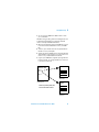
DCC Port
Connector
9-pin miniature D-type.
Use this port to insert and drop either the D1-D3 DCC channel
or the D4-D12 DCC channel. The first bit of data inserted will be
put into the MSB of the DCC channel. The MSB of the dropped
data bytes will be output first. The transmit (drop) and receive
(insert) capabilities are independent, that is the transmit and
receive clock rates can be set to different rates. The instrument acts as a DCE (Data Communications Equipment), supplying the clock signal for both drop and insert operation.
Rates
D1-D3 DCC: 192 kb/s, D4-D12 DCC: 576 kb/s
Signal Type Unipolar differential signal as defined in ANSI
EIA-422-B and EIA-423-B.
Input Termination
100 ohms differential.
Input Sensitivity 500 mV over a +/-15 V common mode
range and 200 mV over a +/-7 V range.
28
Pin Number
RS-449/422 Circuit
1
Rx Data Output (+)
2
Rx Clock Output (+)
3
Signal ground
4
Tx Clock Output (+)
5
Tx Data Input (+)
6
Rx Data Output (–)
7
Rx Clock Output (–)
8
Tx Clock Output (–)
9
Tx Data Input (+)
Transmission Test Set Quick Reference Guide
Getting Started
2
Electrical Test Ports
SONET/SDH Out
BNC 75 ohm unbalanced connector for an STS-1/STM-0
(B3ZS) or STS-3/STM-1 (CMI) electrical output.
SONET SDH In
BNC 75 ohm unbalanced connector for an STS-1/STM-0
(B3ZS) or STS-3/STM-1 (CMI) electrical input. Input Mode Terminate or Monitor. Monitor mode conforms to G.772-1993.
Monitor Gain - 20 dB.
2 Mb/s Out
3-pin Siemens 120 ohm balanced connector for an E1 Transmit
or E1 Drop signal output. Either this port or the 2-140 Mb/s
DS3 unbalanced Out port can be active for the E1 Transmit
function.
2 Mb/s In
3-pin Siemens 120 ohm balanced connector for an E1 Receive
or E1 Insert signal input. Either this port or the 2-140 Mb/s DS3
unbalanced In port can be active for the E1 Receive function.
DS1 Out
Bantam 100 ohm balanced connector for a DS1 Transmit or
DS1 Drop output.
DS1 In
Bantam 100 ohm balanced connector for a DS1 Receive or DS1
Insert input.
2-140 Mb/s DS3 Out
BNC 75 ohm unbalanced connector for E1, E2, E3, E4, DS3
transmit or E3, E4, DS3 Drop output signals. Either this port or
the 2 Mb/s balanced Out port can be active for E1 Transmit
function.
Transmission Test Set Quick Reference Guide
29
2
Getting Started
2-140 Mb/s DS3 In
BNC 75 ohm unbalanced connector for E1, E2, E3, E4, DS3
receive or E3 and E4 DS3 Insert input signals. Either this port or
the 2 Mb/s balanced In port can be active for E1.
Ethernet Ports
10M/100M Ethernet Ports
Eight RJ-45 connectors are provided, each of which can support 10 Mb/s or 100 Mb/s data rates.
1G Ethernet Ports
Two Gigabit Interface Convertors (GBICs) are provided as follows:
Instrument Option
Number
Ethernet Type
GBIC
Agilent Part
Number
325
1000BASE-SX (850 nm)
HFBR-5601
326
1000BASE-LX (1310
nm)
HFBR-5611
Tx Eye Clock
SMA connector providing a TX Eye Clock signal that can be
used to trigger an oscilloscope when examining data signals.
30
Transmission Test Set Quick Reference Guide
Getting Started
2
Left Side Panel Tour
External
Protective
Earth
Floppy
Disk Drive
GPIB
GPIB
Allows test set to be remotely controlled via the GPIB control
bus.
External Protective Earth
Connect an external earth connection to the instrument at this
point.
Floppy Disk Drive
Accepts 1.44 MB IBM formatted disks.
Transmission Test Set Quick Reference Guide
31
2
Getting Started
Right Side Panel Tour
LAN 10M/100M
Mouse
USB
Keyboard
RS232
Power
On/Off
VGA
LAN 10M/100M
10/100 Base-T LAN interface port. Supports remote control of
test set and the downloading of firmware upgrades.
10 Base-T LAN Connection Radiated Emissions: To ensure
compliance with EN 55011 (1991) a category 5, STP patch lead,
RJ45 cable should be used to connect to the LAN port.
Mouse
PS/2 port for connecting a mouse. Activation of this port is
planned as a future enhancement, (no timing details available
at time of printing).
USB
Two Universal Serial Bus ports for connecting to a Printer.
32
Transmission Test Set Quick Reference Guide
Getting Started
2
Keyboard
PS/2 port for connecting an external keyboard. Can be
hot-plugged for use at any time. Ensure that keyboard port is
used - if connected to mouse PS/2 port in error the instrument
will require to be restarted.
RS232
Remote Control port providing following configurations:
• Controller Type: Computer and Terminal.
• Protocol: None and Xon/Xoff.
• Speed: 110, 300, 600, 1200, 2400, 4800, 9600, 19200, 38400
baud.
• Parity: Odd, Even, 1s, 0s.
• Stop Bits: 1, 2
• Data Length: 7 bits.
VGA
Connector for displaying contents of instrument screen on an
external display. Ensure that the external display is connected
before powering up the instrument.
Transmission Test Set Quick Reference Guide
33
2
Getting Started
Using a Mouse and Keyboard
Mouse
Keyboard
Power
On/Off
Mouse Port (PS/2) You can use an external mouse (to point
and click) instead of the arrows and <Select> key to select
instrument settings on the display.
Keyboard Port (PS/2) You can use an external keyboard
instead of the front panel keypad to enter data. The keyboard
can be connected to the instrument at any time.
N O TE
NOTE
If you connect the keyboard to the Mouse Port
(PS/2), the keyboard will not function. Re-connect the
keyboard and mouse to the correct ports, then restart
the instrument.
To prevent possible damage the mouse should only be
connected and disconnected when the instrument is
powered off.
34
Transmission Test Set Quick Reference Guide
Getting Started
2
Selecting SONET or SDH Operation
The instrument is a dual standard SONET/SDH instrument.
Select the standard you require as follows:
1 Press the <Menu> key and select System > Preferences.
2 Press <Select> to open the Preferences window. Select
SONET or SDH as required.
Transmission Test Set Quick Reference Guide
35
2
36
Getting Started
Transmission Test Set Quick Reference Guide
Agilent J2126/7A Transmission Test Set Quick
Reference Guide
3
Using the Graphical User
Interface
Display Windows 38
Menus 40
Basic User Interface Operations 41
The graphical user interface (GUI) with windows, menus and
dialogs provides easy access to all the instrument setup, monitoring and results pages together with constant display of context-sensitive help and instrument status. The interface also
allows you to use the built-in help system which gives detailed
information on using the instrument.
Agilent Technologies
37
3
Using the Graphical User Interface
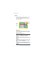
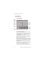
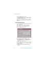
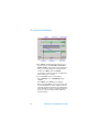
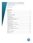
Display Windows
Instrument Windows
Window
Title Bar >
Field
>
Highlight
Active
Window >
(magenta
border)
Summary
Window >
Status >
Information
Inactive
< Window
(gray
border)
ContextSensitive
< Help
Message
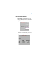
Two main instrument windows display the pages for setting
up, monitoring and viewing results.
Only one of these windows is active at a time. The active window is indicated by a colored (magenta) border. Change the
active window by pressing the <Window> button next to the
arrow navigation keys.
Move around within a window by using the arrow navigation
keys. The current position on the window is shown by a red
highlight box around the control field.
The title of the current displayed page is given at the top of the
window in the title bar. This also gives the menu name that the
page has come from, for example Overhead Setup - Trace Messages is the Trace Messages page selected from Overhead
Setup on the menu.
A single line of Context-sensitive help appears at the bottom of
the display. This gives you helpful information relating to the
area of the screen that is highlighted by the red box.
The Status line displays the instrument and keyboard status.
38
Transmission Test Set Quick Reference Guide
Using the Graphical User Interface
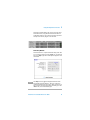
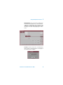
3
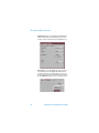
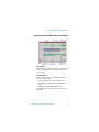
The Summary window displays the current setup of the Transmitter and Receiver, along with Transmit Function Indicators
and the Elapsed Time for the current measurement period. An
example of the summary diagram is shown below.
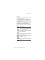
Online Help Window
The instrument has a comprehensive built in help system. This
is accessed at any time by pressing <Help>. To close the help
just press <Help> again. The online help is displayed in a full
size window.
N O TE
The <Help> button toggles the display between the online
help and the instrument windows – when you go back into
online help it will be in the same page as when you left it. If you
want to return to the Home Page of the online help, press the
<Home> key on the instrument keypad.
Transmission Test Set Quick Reference Guide
39
3
Using the Graphical User Interface
Menus
All instrument pages are accessed through the instrument’s
menu system by selecting an item from the menu. To display
the main menu press <Menu>.
The focus will be on the first menu item and the submenu will
also be displayed. As you move the focus down the menu, the
submenu will automatically be displayed.
To select an item from the menu use the up/down arrow navigation buttons to move the focus through the main menu and
the left/right arrow navigation buttons to move in and out of
the submenus. To select a menu item press <Select>.
A menu is also available in the online help system to allow you
to quickly navigate through the help system and provides quick
access to the index and glossary. To display, press <Menu>,
while in online help.
40
Transmission Test Set Quick Reference Guide
Using the Graphical User Interface
3
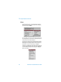
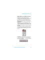
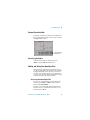
Basic User Interface Operations
To use a
• Drop down list box – move the highlight onto the control
field and press <Select>. Use the arrow navigation buttons
to highlight your choice, then press <Select>. To close the
drop down list without making a selection press <Cancel>
Drop down lists are used where multiple choices are available. For example, in the Errors window you select the Error
Type from the two drop-down lists.
Transmission Test Set Quick Reference Guide
41
3
Using the Graphical User Interface
• Folder/tab selector – some windows have multiple pages
within a window which are separated by the use of folders/tabs. To select a folder/tab move the highlight onto it.
• Text entry box – move the highlight onto the control field.
For quick text entry use the keypad which will be in text
mode. (See “Keypad” on page 20 for details on how to use
the keypad to enter text). Press <Select> to display a list of
presets, Edit Field and a list of the most recently used text.
42
Transmission Test Set Quick Reference Guide
Using the Graphical User Interface
3
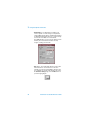
• Numeric entry box – move the highlight onto the control
field. You can edit values using the keypad, Live Edit or Edit
Field. Or you can choose from the preset or most
recently-used values listed in the drop down menu. For
quick numeric entry, use the keypad to enter the value, then
press <Select> to save your entry. Alternatively, press
<Select> to display a drop down list of min/max settings,
Edit Field, Live Edit and a list of the most recently used values for that field.
Edit Field allows you to select individual digits and edit
them using the keypad. This is useful when you want to edit
one digit of an eight digit number. Press <Select> to enter
the value. Each time you enter a new value, the focus moves
to the right.
Live Edit allows you to increment or decrement a value during a measurement, using the arrow navigation keys. Use
the left/right arrow keys to highlight the digit to be changed
and use the up/down arrow keys to increase or decrease
the value.
• Action Buttons – These are used to process an action. For
example, in Pointer Adjustment, to action a pointer burst
you would move the highlight to the Transmit Pointer Burst
button and press <Select>.
Transmission Test Set Quick Reference Guide
43
3
Using the Graphical User Interface
• Modal window – a modal window is used when some
action is required on certain settings. For example when
setting up Measurement Timing - the Measurement Timing
modal window will be displayed for you to setup the timing.
You must then select Close to close the window.
The <Cancel> button can also be used to quickly close the
window - please note that this does NOT cancel any
changes or settings you have made.
• More button – this is indicated by three dots and is used to
indicate that there is more information on selections
available. To use this move the highlight to the button and
press <Select>. For example, in the mapping setup area of
the Transmitter Settings pages, select the More button to
open the mapping diagram.
44
Transmission Test Set Quick Reference Guide
Using the Graphical User Interface
3
• Mapping Diagram – this is used to select a mapping structure. Use the arrow navigation keys to select the required
mapping. Press <Select> when you have finished, or press
<Cancel> to close the mapping diagram without changing
the settings. An example of a mapping diagram is shown
below.
• Checkboxes – these are used to set a control either OFF or
ON. For example, to enable Thru Mode move the highlight to
the checkbox and press <Select>.
Transmission Test Set Quick Reference Guide
45
3
46
Using the Graphical User Interface
Transmission Test Set Quick Reference Guide
Agilent J2126/7A Transmission Test Set Quick
Reference Guide
4
Using Online Help
Which Keys Do I Press? 48
Context-Sensitive Help 49
Accessing the Index 49
Adding and Using Your Own Help Files 49
The Online Help provides you with full information on how to
set up and use the instrument. A comprehensive index and
glossary are included.
One of the main features of the instrument is the ability to add
your own help files. This chapter tells you how to do this.
Agilent Technologies
47
4
Using Online Help
Which Keys Do I Press?
Press this when you need to refer to the
online help. Press it again to take you
back to the instrument settings.
Returns you to the Home page.
Home
Back
Fwd
The <Back> and <Fwd> keys are used
the same way as in a typical Web
browser - Use the <Back> key to go
back to the previous page and, if you have
just used the <Back> key for navigating
then the <Fwd> key takes you forward
to where you have come from.
Next
Page
Prev
Page
These key are used in the same way as
Page Up and Page Down on your PC.
When there is more information on a
page than can be viewed at any one time,
use the <Prev Page> and <Next Page>
keys to scroll the display.
Pressing <Menu> displays a drop-down
list of the main contents of the online
help. Use the Arrow keys to highlight
what you want to view, then press
<Select>.
Most of the pages of online help have
several links to more information. The
link that is currently active is highlighted.
To follow the link, just press the
<Select> key.
If the link you want to follow is not highlighted, use the <Arrow Navigation>
buttons to highlight what you want to
view, then press <Select>.
48
Transmission Test Set Quick Reference Guide
Using Online Help
4
Context-Sensitive Help
A single line of text appears at the bottom of the display. This
gives you helpful advice relating to the area of the screen that
is highlighted by the red box.
Context-Sensitive
< Help Message
Accessing the Index
To find information quickly on a particular topic press
<Menu> and select Index when in Help mode.
Adding and Using Your Own Help Files
One of the benefits of this Transmission Test Set is that you
can add your own help files to the instrument and access them
through the Online Help system. This may be a useful tool if
you wish to store specific instructions for your technicians to
carry out routine procedures, help them with problem solving,
or detail test procedures that they should follow.
Accessing Your Own Help Files
To access your own help files that you have installed on the
instrument, press <Help> + <Menu> on the instrument
panel, and select Your Own Help.
The names of your own help files will then be displayed as a
list of links. To access a particular file, move the focus on to
the link and press <Select>.
Transmission Test Set Quick Reference Guide
49
4
Using Online Help
Create Your Own Help Files
The help files you create to install on the instrument must be in
HTML format. You can create them using an HTML editor tool,
or with a word processor that will save them as HTML files.
When creating your files for online use follow these simple
guidelines:
• Use only a sans serif type font (such as Arial) of size 12, 14
or 16 point, Normal or Bold - DO NOT use italic as this font
is not supported on the instrument and can cause problems
with the presentation of your document.
• Any images you include should be either GIF or JPEG.
• Write several short documents rather than one long one. A
long document takes longer to open.
• Design a page size and layout that’s appropriate for the size
of the instrument display.
• Have all the documents and images in one folder/directory.
The instrument does not currently support file tree structures.
• Total size of the files should not be more than 1.44Mb.
CAU T ION
The instrument supports HTML Standard 3.2 - presentation
or operation of elements using later HTML standards are
not guaranteed to operate or display on the instrument.
The following procedure was used to create the example help
files that are installed in the instrument - you can view the
results on the online help in the ‘Users Own Help Files’ section.
N O TE
The example help files can be copied from the instrument and
amended for your own use. See “Copy Your Own Help Files to
Disk” on page 53.
1 A standard word processor was used to create the content.
Keeping your document short, two pages or so, will make it
quicker to load and navigate when on the instrument.
2 Save the document as HTML with the file extension html
NOT htm.
50
Transmission Test Set Quick Reference Guide
Using Online Help
4
3 You can open your HTML file in a Web browser to check
your converted file.
TIP: When saving your files, give them a meaningful name as it
is this filename that will appear as a link in the index file
online. For example ‘AtlantaBasinTest5.html’.
4 When you have finished creating your HTML files you must
now create an index file with links to each of your HTML
files.
5 To do this, open a new file and create a hypertext link from
this file to each of your help files.
6 Save the document as HTML. You must name this index file
ownhelp.html. It is important that you use this name as it is
used to access your files within the instrument.
7 Copy all of your HTML files, along with any image files that
have been created, onto a floppy disk which you now need
to install on the instrument.
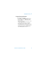
Network Test
Test 1
Test 1
Test 2
Test n
Filename:
Test1.html
Filename:
ownhelp.html
Test 2
Index file (ownhelp.html) with
links to individual test files
Filename:
Test2.html
Transmission Test Set Quick Reference Guide
51
4
Using Online Help
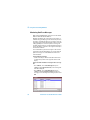
Adding/Updating Your Own Help Files
You can add or update your own help files to the instrument by
downloading them from a floppy disk.
N O TE
Your files must all have the extension html, with images as jpg
or gif. Remember, your main index file must be named ‘ownhelp.html’ and be loaded into the instrument in order for the
links to operate.
1 Insert the floppy disk into the disk drive on the left side of
the instrument.
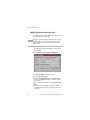
2 Press <Menu> and select System > File Manager.
3 Select the User Help folder as shown above.
4 Set the Drive field to Floppy.
5 Select the Operation field and choose Refresh List. Move
the focus to the Action field and press <Select> to refresh
the list of files.
6 Select the Operation field and choose Copy all files to User
Help.
7 Move the focus to the Action button and press <Select>.
Your files will now be uploaded from the floppy disk to the
instrument.
52
Transmission Test Set Quick Reference Guide
4
Using Online Help
To update files you have already installed in the instrument,
repeat the steps 1 to 7, but for step 7 Select the Operation field
and choose Copy file to User Help - you can then select the
update file you want to install.
N O TE
When adding files to the instrument any files with the same
name will be overwritten and new files will be added.
8 To check that you can access the files, press <Help> +
<Menu> on the instrument panel, and select Your Own
Help.
Copy Your Own Help Files to Disk
To copy files from the instrument to a floppy disk:
1 Insert a floppy disk into the disk drive on the left side of the
instrument.
2 Press <Menu> and select System > File Manager.
3 Press <Select> to open the File Manager window.
4 Select the User Help folder as shown.
5 Set the Drive field to Internal.
6 Select the Operation field, press <Select> and choose
Refresh List. Move the focus to the Action field and press
<Select> to refresh the list of files.
Transmission Test Set Quick Reference Guide
53
4
Using Online Help
7 Select the Files field and choose a file.
8 Select the Operation field and choose Copy file to floppy or
Copy all files to floppy as required.
9 Move the focus to the Action button and press <Select>.
Your files will now be downloaded from the instrument to the
floppy disk.
Delete Your Own Help Files
You can use File Manager to delete User Help files stored internally or on a floppy disk.
1 Press <Menu> and select System > File Manager.
2 Press <Select> to open the File Manager window.
3 Select the User Help folder as shown.
4 Set the Drive field to Internal or Floppy as required.
5 Select the Operation field, press <Select> and choose
Refresh List. Move the focus to the Action field and press
<Select> to refresh the list of files.
6 Select the Files field and choose the file you wish to delete.
7 Select the Operation field and choose Delete file or Delete
all files as required.
8 To delete the file/files select the Action field and press
<Select>.
54
Transmission Test Set Quick Reference Guide
Agilent J2126/7A Transmission Test Set
Quick Reference Guide
5
Using Multiple
Instruments
Products Supported 56
Feature Summary 56
Foreground Instrument Selection 57
Agilent Technologies
55
5
Using Multiple Instruments
Products Supported
This product supports multiple instruments, namely:
SONET/SDH
Ethernet
Up to 10 Gb/s line rates
T-carrier (DS1/DS3)
PDH (2/8/34/140 Mb/s)
2-port 1 Gb/s
8-port 10/100 Mb/s
Feature Summary
• These instruments continue to transmit and receive, and
make measurements irrespective of which is the foreground
instrument.
• The main menu changes to contain the selections for just
the foreground instrument.
• The <Run/Stop> key controls measurements on foreground
and background instruments simultaneously.
• The <Smart Test>, <Single Error>, <Show More>, <Reset>
and <Print Control> keys operate on the foreground instrument.
• The front panel Signal, Frame, Pattern, Errors, SONET/SDH,
DSn, PDH and History LEDs operate only on the foreground
instrument.
• The Multiple Instruments LED indicates errors or alarms in
all background instruments. If on, check the Multiple Instruments > Status page to locate the problem.
• Trouble Scan/Results Summary operates only on the foreground instrument.
• A Multiple Instruments Status page is available. It is a full
product SONET/SDH Trouble Scan and Ethernet Results
Summary.
56
Transmission Test Set Quick Reference Guide
Using Multiple Instruments
5
Foreground Instrument Selection
To select the foreground instrument
• Press <Menu>, choose Multiple Instruments > Select
then press <Select>. Choose SONET/SDH or Ethernet
then press <Select>.
The name of the selected foreground instrument is shown
at the top of the main menu.
A combined SONET/SDH Trouble Scan and Ethernet
Results Summary report is available. Press <Menu>,
choose Multiple Instruments > Status then press <Select>.
A summary of the main features of Multiple Instruments is
also available. Press <Menu>, choose Multiple Instruments > Quick Help then press <Select>.
Transmission Test Set Quick Reference Guide
57
5
58
Using Multiple Instruments
Transmission Test Set Quick Reference Guide
Agilent J2126/7A Transmission Test Set Quick
Reference Guide
6
Using Smart Test and
SignalWizard
Shortcuts to Results, Measurements and
Stored Settings 60
Resetting Instrument to Default Settings
60
Using the SignalWizard Test Feature 61
Understanding SignalWizard Overview
Window 63
You can use Smart Test to access the SignalWizard feature
(when the foreground instrument is set to SONET/SDH) or to
the RFC Conformance Tests (when set to Ethernet). It also provides shortcuts to results, measurements and stored settings.
Smart Test also allows you to reset the instrument to its
default settings.
To access Smart Test features:
• Press <Smart Test> then select the appropriate feature
from the drop-down menu using the arrows and <Selects>
keys.
Agilent Technologies
59
6
Using Smart Test and SignalWizard
Shortcuts to Results, Measurements and Stored
Settings
You can use Smart Test to access results, measurements and
stored settings.
To access shortcuts:
1 Press <Smart Test>, choose Shortcuts. Select an item
from the list and press <Select>.
2 Select an item from the list of shortcuts.
Resetting Instrument to Default Settings
You can use the Smart Test to reset the instrument to its
default values.
To reset instrument to default settings
1 Press <Smart Test>, choose Reset Instrument then press
<Select>.
2 Select OK in the “Warning” window to reset the instrument
settings.
60
Transmission Test Set Quick Reference Guide
Using Smart Test and SignalWizard
6
Using the SignalWizard Test Feature
SignalWizard checks the test ports for valid signals. A signal is
valid if its power level and frequency are with in the specified
limits of the port it is connected to. The line rate and interface
level for optical signals is determined along with the termination, signal level and line coding for electrical signals.
SignalWizard then scans all STS/AU channels (up to 192) and
selected 'expanded' VT/TU channels simultaneously for error
and alarm information. For VT/TU channels that are not
'expanded' in the display, error and alarm information is
obtained sequentially (within milliseconds).
SignalWizard can also scan PDH/DSn sub-channels, and
shows which channels are unequipped and the type of service
being carried by equipped channels.
For information on connecting to a network when testing with
SignalWizard, see:
• “In-Service Testing” on page 68
• “Out-of-Service Testing” on page 69
To monitor a signal with SignalWizard:
1 Press <Smart Test>, choose SignalWizard then press
<Select>.. A progress indicator is displayed. If more than
one valid signal is detected, the port selection window is
displayed. Select the port you want to examine, then select
Continue. If only one valid signal is detected or if the instrument is in Thru-Mode, the Channel Overview window will
automatically appear on the display. For information, see
“Understanding SignalWizard Overview Window” on
page 63.
If SignalWizard detects a DSn/PDH signal, then PDH/DSn
Channel Scan will automatically be launched. A window
will appear showing the status and structure of all channels.
If no valid signal is detected, you can re-scan the ports or
return to the main instrument.
Transmission Test Set Quick Reference Guide
61
6
Using Smart Test and SignalWizard
2 Press <Menu> to further investigate channels, errors or
path trace messages (select Next Error, Previous Error,
Expand or Collapse). If any STS/AU contains VT/TU tributaries, you can view a tributary in more detail. Select the
channel, press <Menu>, then select Expand.
For information on path trace messages, see “Monitoring
Path Trace Messages” on page 66.
3 To close SignalWizard, do one of the following:
Press <Smart Test>, choose Stop Wizard then press
<Select>.
Press <Menu>, choose Exit then press <Select>.
Before closing SignalWizard, you can automatically configure the transmitter and/or receiver settings to match the
signal being applied to the instrument (not available in Thru
mode). This feature is useful if you intend doing further testing. It saves you from having to manually configure the
instrument settings.
62
Transmission Test Set Quick Reference Guide
Using Smart Test and SignalWizard
6
Understanding SignalWizard Overview Window
Signal Viewer
Displays the detected signal. If a J0 trace message is detected
this is also displayed (both 16- and 64-byte message formats
are supported).
Overhead Viewer
Displays results information associated with the overhead
layer of the signal, including:
• Synchronization status message (decoded S1 byte)
• CV-S (RS-BIP), CV-L (MS-BIP) and REI-L (MS-REI) error
status
• AIS-L (MS-AIS) and RDI-L (MS-RDI) alarm status
(LOS and LOF alarms are displayed on the instrument’s front
panel LEDs.)
Transmission Test Set Quick Reference Guide
63
6
Using Smart Test and SignalWizard
Selected Channel Viewer
Displays result information associated with the selected channel, including:
• Type of payload (traffic) being carried in the channel
(decoded C2 byte)
• CV-P (HP-BIP) and REI-P (HP-REI) error status
• AIS-P (AU-AIS), LOP-P (AU-LOP) and RDI-P (HP-RDI) alarm
status
• Indicator for detected pointer adjustments
J1 Trace Message
Displays the decode path trace message associated with the
selected channel. Both 16- and 64-byte messages formats are
supported.
Channel Viewer
The Overview window shows a summary (using color coding,
see the following table) of the results for all channels. Each
channel detected in the signal is provided with a dedicated box
that summarizes the channel status. A channel carrying
VT/TU channels is highlighted by its size designator being
underlined. Broadband mappings are not underlined.
The size designator displayed within each box. While any
non-standard concatenated channels will be detected and displayed, no errors or alarms are reported for that channel.
Unequipped channels are displayed on a grey background.
Pointer activity within a channel is indicated by the channel
background flashing blue.
64
Transmission Test Set Quick Reference Guide
Using Smart Test and SignalWizard
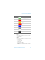
Color Coding
Result
Green
No Errors/Alarms detected during test
or since the last history reset
Red
Errors/Alarms detected
Yellow
History (Errors/Alarms detected in the
past)
Red/white A
AIS (STS-1, STS-3c/STM-0, STM-1)
Blue
Pointer Move
Grey
Unequipped
White/black dot
Other Standard
Black
Illegal Pointer Combination
6
Errors
An Error flag is raised when one or more errors occur in any
one sampling period.
Alarms
An Alarm flag is raised when one or more alarms occur in any
one sampling period.
• Loss of Pointer LOP
• Path AIS (AIS-P)
• Remote Path Alarm (RDI-P)
• Pointer Adjustment LOP (LOP flashes blue on each adjustment)
Transmission Test Set Quick Reference Guide
65
6
Using Smart Test and SignalWizard
Monitoring Path Trace Messages
When running SignalWizard any routing errors in the network
will be shown in the Overview window.
During the installation and commissioning of new services, or
troubleshooting, the ability to generate and monitor path trace
messages is essential. This allows you to confirm correct routing paths through network equipment with software controlled
routing capability. You can also use path trace messages for
checking routing performance of network elements during protection switching to confirm the correct signals have been protected in fault conditions.
You can view all the J1 path trace messages for the received
signal at the same time. Alternatively, you can view all the J2
path trace messages associated with VT/TU channels in a
selected STS/AU.
To view path trace messages:
• Use the arrow keys to select the STS/AU channel of interest. View the J1 path trace message at the bottom of the
display.
To list/search all J1 Path trace messages in the receive signal:
• Press <Menu>, choose Trace Messages then press
<Select>. Select List Current Levels, a trace message window will be displayed.
• Press <Menu>, choose Trace Messages then press
<Select>. Select Search Current Level. Enter the trace
message you are searching for in the dialog box, then select
OK.
66
Transmission Test Set Quick Reference Guide
Using Smart Test and SignalWizard
6
To view J2 Path trace messages in VT/TU channel:
1 Use the arrows to highlight the channel for further analysis.
2 Press <Menu>, choose Expand then press <Select>. This
expands the VT/TU substructure.
3 Press <Menu>, choose Collapse then press <Select>.
This closes the VT/TU substructure.
N O TE
STS/AU channels that contain VT/TU channels are shown
underlined on the display.
Transmission Test Set Quick Reference Guide
67
6
Using Smart Test and SignalWizard
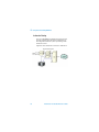
In-Service Testing
You can use SignalWizard to simultaneously monitor all channels in the received signal. This feature is useful when commissioning new transmission systems or performing routine
maintenance checks.
A typical in-service network test connection is shown below.
68
Transmission Test Set Quick Reference Guide
Using Smart Test and SignalWizard
6
Out-of-Service Testing
You can use the instrument transmitter in conjunction with
SignalWizard all channel test feature to test each path carried
within a tributary or line signal. You can apply the test signal to
the tributary or line side of the network element.
Applying a test signal to the line side of the network element
may reduce the number of ports that need to be checked. SignalWizard will identify the type of network paths present in the
received signal (including the mix of channel types), and the
traffic carrying status of each channel (showing which are
equipped).
Typical tributary and line network test connections are shown
below.
Tributary-Side Testing Setup
Line-Side Testing Setup
Transmission Test Set Quick Reference Guide
69
6
70
Using Smart Test and SignalWizard
Transmission Test Set Quick Reference Guide
Agilent J2126/7A Transmission Test Set Quick
Reference Guide
7
Hints and Tips
Avoiding Problems When Making
Measurements 72
Avoiding Optical Receiver Overload 73
Cleaning Optical Connectors 74
Front Panel Soft Recovery (Cold Start) 75
Agilent Technologies
71
7
Hints and Tips
Avoiding Problems When Making
Measurements
Bit errors can occur due to network defects (such as faulty network elements, damaged optical fiber or dust/dirt particles in
the fiber connections) or problems with the test environment/setup. Follow the steps below to avoid problems when
making measurements.
To avoid introducing errors when performing tests:
• Ensure that optical fibres connecting the instrument to the
network are not damaged - check that fibres have not been
crimped.
• Avoid acute bends in the fibre. Ensure that fibres only have
gentle arcs.
• If the instrument is left unattended for a long term test,
ensure that the equipment is not in a position where people
will disturb the connecting fibers.
• Ensure that all fiber connections are clean and dirt-free. Use
a fiberscope to measure the cleanliness of a (unpowered)
fiber. A poorly cleaned fiber results in a drop in power. Alternatively, use a power meter (e.g. the instrument’s internal
power meter) to measure the power at the end of a fiber, the
other end of which is connected to the network.
• Before connection is made, always clean the connector ferrule tip with acetone or alcohol using a cotton swab. Dry the
connector with compressed air. Failure to maintain cleanliness of connectors is liable to cause excessive insertion
loss.
• Ensure that the correct time and date is set on the instrument.
72
Transmission Test Set Quick Reference Guide
7
Hints and Tips
Avoiding Optical Receiver Overload
Check when connecting an optical transmitter to an optical
receiver that you do not overload the receiver. This applies to
elements under test and also the instrument receiver input
ports.
On the instrument connector panel the following output/input
power level information is printed:
Tx Optical Out
ports:
Maximum available output power
(color - black).
Rx Optical In ports:
Maximum input power (damage
level) the receiver input can accept
before damage occurs
(color - yellow).
Recommended input power operating range for signals applied to the
receiver (color - green).
When performing tests, it is recommended that you drive the
optical receiver with a signal that has an average power in the
middle of the receiver’s operating range (mid-way between the
upper and lower levels printed next to the Optical In port).
Transmission Test Set Quick Reference Guide
73
7
Hints and Tips
Cleaning Optical Connectors
You should clean the optical connectors at regular intervals
using the following materials:
Description
Agilent Part Number
Compressed Air Can or
Blow Brush
CAU T ION
Isopropyl Alcohol
8500-5344
Lens Cleaning Paper
9300-0761
Swabs
5080-5400
Do not insert any tool or object into the optical IN or OUT
ports of the instrument as damage to or contamination of
the optical fiber may result.
1 Disconnect the instrument from the Power Line or switch
off the laser transmitter before commencing this cleaning
procedure.
2 Remove the adapters from the optical IN and OUT ports by
flipping back the lever on the optical adapter.
3 Using the blow brush with the brush removed blow through
the ferrule of the standard flexible connector and the
adapter.
4 If the optical fibre of the fixed connector requires further
cleaning this entails disassembly of the module. This should
be carried out only by suitably trained service personnel.
5 Apply some isopropyl alcohol to a piece of the cleaning
paper and clean the barrel of the adapter. Using a new piece
of cleaning paper, clean the face of the adapter. Repeat this
operation, using a new piece of cleaning paper each time.
6 Use a blow brush or compressed air to remove any particles
of cleaning paper which may be present.
7 Replace the adapters in the optical connector. Secure in
place by clicking the retaining lever back into position.
74
Transmission Test Set Quick Reference Guide
7
Hints and Tips
Front Panel Soft Recovery (Cold Start)
An instrument “cold start” routine is provided to reset the
instrument in the event of an unplanned hardware or firmware
event. AA cold start reboots the instrument and restarts the
instrument using a default configuration file. Performing a cold
start erases existing configuration information.
Performing a Cold Start
1 Switch the instrument off and wait a few seconds.
2 Switch the instrument on and as the instrument boots up,
look carefully at the display.
3 Wait for the “Starting instrument” . . . . . text to be displayed.
After a few seconds start to repeatedly press the <Menu>
key until the Agilent splash screen appears with an options
menu in the top left corner of the display.
The following options are available:
1 Reload configuration.
3 Cold start.
5 Normal start.
6 Upgrade software.
4 Press 3 on the numeric keypad to select cold start.
5 The unit will then continue with the boot up process.
6 When the boot-up procedure is complete, the instrument
displays a dialog box with the message
“Instrument reset to default settings.”
Transmission Test Set Quick Reference Guide
75
7
76
Hints and Tips
Transmission Test Set Quick Reference Guide
Agilent J2126/7A Transmission Test Set Quick
Reference Guide
8
Quick Reference Tables
Smart Test 78
Print Control 79
Multiple Instruments 79
SONET/SDH Transmitter Functions 80
SONET/SDH Receiver Functions 82
SONET/SDH Test Functions 90
SONET/SDH Overhead Setup 84
SONET/SDH Overhead Monitor 86
SONET/SDH Results 88
Ethernet Functions 91
System Functions 92
System Functions – Measurement Logging
93
System Functions – File Manager 94
Only the main selections are listed here. It is assumed that the
user understands that once a field is selected that the front
panel <Select> button is then pressed to make the selection
or to open the window.
Agilent Technologies
77
78
Path
With SONET/SDH as Foreground instrument:
Press <Smart Test>, choose SignalWizard then press <Select>.
With Ethernet as Foreground instrument:
Press <Smart Test>, choose RFC 2544 Test & Results then press <Select>.
Press <Smart Test>, choose Shortcuts. Select an item from the list and press
<Select>.
Press <Smart Test>, choose Reset Instrument then press <Select>.
SignalWizard
Ethernet RFC 2544 conformance tests
Shortcuts to frequently-used features
Reset Instrument to default settings.
You can use the front panel <Smart Test> button to quickly select one of the following:
Use the front panel <Smart Test> and <Print Control> buttons for fast selection of
SignalWizard, Ethernet RFC 2544 conformance tests, Measurements and Print Control
functions. Use the <Menu> key to access all other functions.
Function – Using Smart Test
Smart Test
Introduction
8
Quick Reference Tables
Transmission Test Set Quick Reference Guide
Press <Menu>, choose System > Measurement Logging then press <Select>.
Press <Print Control>, choose Destination, Printer or File
Copy a snapshot of the logging results to a
Printer/File
Copy a screen dump of current window to a file or
Printer
Path
Press <Menu>, choose Multiple Instruments > Select then press <Select>.
Choose SONET/SDH or Ethernet then press <Select>.
Press <Menu>, choose Multiple Instruments > Status then press <Select>.
Press <Menu>, choose Multiple Instruments > Quick Help then press
<Select>.
Function – Multiple Instruments
Select Foreground instrument
View Status report for Foreground and Background
instruments
View Multiple Instruments Quick Help page
Multiple Instruments
Path
Function – Print Control
Print Control
Quick Reference Tables
Transmission Test Set Quick Reference Guide
8
79
80
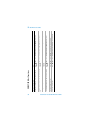
Press <Menu>, choose Tx/Rx > Transmitter Settings then press <Select>.
Then select SDH/SONET.
Press <Menu>, choose Tx/Rx > Transmitter Settings then press <Select>.
Then select PDH/DSn.
Press <Menu>, choose Tx/Rx > Transmitter Settings then press <Select>.
Then select PDH/DSn.
Press <Menu>, choose Tx/Rx > Transmitter Settings then press <Select>.
Then select Pattern.
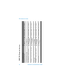
Inserting 2 Mb/s or DS1 into SDH or SONET signal
Setting Tx PDH/DSn framing, test channel and background settings
Inserting 2 Mb/s or DS1 into PDH or DSn signal
Setting Tx test pattern
Press <Menu>, choose Tx/Rx > Transmitter Settings then press <Select>.
Select the Physical tab.
Setting Tx Signal Rate, Interface, Code, Operating
Level (SONET/SDH, PDH and DSn)
Press <Menu>, choose Tx/Rx > Transmitter Settings then press <Select>.
Then select SDH/SONET.
Press <Menu>, choose Tx/Rx > Transmitter Settings then press <Select>.
Setting the Transmit Interface
Setting Tx Mapping (concatenated and TU/VT)
Path
Function – Transmitter Interface
SONET/SDH Transmitter Functions
8
Quick Reference Tables
Transmission Test Set Quick Reference Guide
Path
Press <Menu>, choose Tx/Rx > Transmitter Settings then press <Select>.
Then select SDH.
Press <Menu>, choose Tx/Rx > Thru Mode then press <Select>.
Press <Menu>, choose Tx/Rx > Coupling then press <Select>.
Press <Menu>, choose Tx/Rx > Stored Settings then press <Select>.
Function – Transmitter Interface
Setting TCM in the Transmitter (SDH only)
Setting Thru Mode
Coupling Transmit and Receive Settings
Recall or Save instrument configuration
Quick Reference Tables
Transmission Test Set Quick Reference Guide
8
81
82
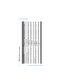
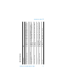
Press <Menu>, choose Tx/Rx > Receiver Settings then press <Select>. Then
select SDH/SONET.
Press <Menu>, choose Tx/Rx > Receiver Settings then press <Select>. Then
select PDH/DSn.
Press <Menu>, choose Tx/Rx > Receiver Settings then press <Select>. Then
select PDH/DSn.
Press <Menu>, choose Tx/Rx > Receiver Settings then press <Select>. Then
select SDH.
Dropping 2 Mb/s or DS1 from SDH or SONET signal
Setting Rx PDH/DSn framing, test channel and background settings
Dropping 2 Mb/s or DS1 into PDH or DSn signal
Setting Tandem Connection Monitoring (SDH only)
Press <Menu>, choose Tx/Rx > Receiver Settings then press <Select>.
Select the Physical tab.
Setting Rx Signal Rate, Interface, Code, Operating
Level (SONET/SDH, PDH and DSn)
Press <Menu>, choose Tx/Rx > Receiver Settings then press <Select>. Then
select SDH/SONET.
Press <Menu>, choose Tx/Rx > Receiver Settings then press <Select>.
Setting the Receiver Interface
Setting Rx Mapping (concatenated and TU/VT)
Path
Function – Receiver Interface
SONET/SDH Receiver Functions
8
Quick Reference Tables
Transmission Test Set Quick Reference Guide
Path
Press <Menu>, choose Tx/Rx > Receiver Settings then press <Select>. Then
select Pattern.
Press <Smart Test>, choose Shortcuts. Select an item from the list and press
<Select>.
Press <Smart Test>, choose SignalWizard then press <Select>.
Press <Menu>, choose Tx/Rx > Coupling then press <Select>.
Press <Menu>, choose Tx/Rx > Stored Settings then press <Select>.
Function – Receiver Interface
Setting Rx test pattern
Using Smart Test shortcuts
Using SignalWizard
Coupling Receive and Transmit Settings
Recall or Save instrument configuration
Quick Reference Tables
Transmission Test Set Quick Reference Guide
8
83
84
Path
Press <Menu>, choose Overhead Monitor > Trace Messages then press
<Select>. Select the required tab.
Press <Menu>, choose Overhead Setup > Trace Messages then press
<Select>.
Press <Menu>, choose Overhead Setup > Labels then press <Select>.
Press <Menu>, choose Overhead Setup > APS Messages then press
<Select>.
Press <Menu>, choose Overhead Setup > H4 Sequence then press <Select>.
Press <Menu>, choose Overhead Setup > Byte Setup then press <Select>.
Press <Menu>, choose Overhead Setup > DS3 FEAC then press <Select>.
Press <Menu>, choose Overhead Setup > DS1 Loopcodes then press
<Select>.
Function – Selecting Transmitter Overhead
Setting Transmit Overhead Setup
Setting Tx Overhead Trace Messages
Setting Tx Overhead Labels (Signal Labels, Sync Status)
Setting Tx Overhead APS Messages
Setting Tx Overhead H4 Sequence
Setting Tx Overhead Bytes
Setting Tx DS3 FEAC
Setting Tx DS1 Loopcodes
SONET/SDH Overhead Setup
8
Quick Reference Tables
Transmission Test Set Quick Reference Guide
Path
Press <Menu>, choose Overhead Setup > Spare Bits then press <Select>.
Press <Menu>, choose Overhead Setup > Signaling Bits then press <Select>.
Press <Menu>, choose Overhead Setup > Restore Defaults then press
<Select>.
Function – Selecting Transmitter Overhead
Setting Tx Spare Bits
Setting Tx Signaling Bits
Restore Byte Default values
Quick Reference Tables
Transmission Test Set Quick Reference Guide
8
85
86
Path
Press <Menu>, choose Overhead Monitor > Trace Messages then press
<Select>. Select the required tab.
Press <Menu>, choose Overhead Monitor > Trace Messages then press
<Select>.
Press <Menu>, choose Overhead Monitor > Labels then press <Select>.
Press <Menu>, choose Overhead Monitor > APS Messages then press
<Select>.
Press <Menu>, choose Overhead Monitor > H4 Sequence then press
<Select>.
Press <Menu>, choose Overhead Monitor > Byte Monitor then press
<Select>.
Press <Menu>, choose Overhead Monitor > DS3 FEAC then press <Select>.
Function – Selecting Receiver Overhead Monitor
Using Rx Overhead Monitor
Using Rx Overhead Monitor Trace Messages
Using Rx Overhead Monitor Labels (Signal Labels,
Sync Status)
Using Rx Overhead Monitor APS Messages
Setting Rx Overhead Monitor H4 Sequence
Using Rx Overhead Monitor Bytes
Setting Rx DS3 FEAC
SONET/SDH Overhead Monitor
8
Quick Reference Tables
Transmission Test Set Quick Reference Guide
Path
Press <Menu>, choose Overhead Monitor > DS1 Loopcodes then press
<Select>.
Press <Menu>, choose Overhead Monitor > Spare Bits then press <Select>.
Press <Menu>, choose Overhead Monitor > Signaling Bits then press
<Select>.
Press <Menu>, choose Overhead Monitor > Sa Bits then press <Select>.
Function – Selecting Receiver Overhead Monitor
Setting Rx DS1 Loopcodes
Setting Rx Spare Bits
Setting Rx Signaling Bits
Setting Rx Sa Bits
Quick Reference Tables
Transmission Test Set Quick Reference Guide
8
87
88
Path
Press <Menu>, choose Results > Trouble Scan then press <Select>.
Press <Menu>, choose Results > Measurement Timing then press <Select>.
Press <Menu>, choose Results > Alarm Seconds then press <Select>.
Press <Menu>, choose Results > Error Summary then press <Select>.
Press <Menu>, choose Results > Errors then press <Select>.
Press <Menu>, choose Results > Performance Analysis then press <Select>.
Press <Menu>, choose Results > Network Measurements then press
<Select>. Select the Pointers tab.
Press <Menu>, choose Results > Network Measurements then press
<Select>. Select the Service Disruption tab.
Press <Menu>, choose Results > Network Measurements then press
<Select>. Select the Round Trip Delay tab.
Function – Results and Measurement Timing
View Trouble Scan Result
Select Measurement Timing
View Alarm Seconds
View Measurement Error Summary
View Measurement Errors
View Performance Analysis
View Pointer Activity
View Service Disruption
Measure Round Trip Delay
SONET/SDH Results
8
Quick Reference Tables
Transmission Test Set Quick Reference Guide
Path
Press <Menu>, choose Results > Signal Quality then press <Select>. Select
the Frequency tab.
Press <Menu>, choose Results > Signal Quality then press <Select>. Select
the Optical Power tab.
Press <Menu>, choose Results > Signal Quality then press <Select>. Select
the Pulse Mask tab.
Press <Menu>, choose Measurement Record > Graph Manager then press
<Select>.
Function – Results and Measurement Timing
Measure Frequency
Measure Optical Power
Measure Pulse mask
View graph of Pointer movement
Quick Reference Tables
Transmission Test Set Quick Reference Guide
8
89
90
Path
Press <Menu>, choose Test Functions > Errors and Alarms then press
<Select>.
Press <Menu>, choose Test Functions > Frequency Offset then press
<Select>.
Press <Menu>, choose Test Functions > Pointer Adjustment then press
<Select>.
Press <Menu>, choose Test Functions > DCC Drop/Insert then press
<Select>.
Press <Menu>, choose System > Self Test then press <Select>.
Press <Menu>, choose Test Functions > Switch Off then press <Select>.
Function – Test Functions
Adding Errors and Alarms to the transmit signal
Adding Frequency Offset to the transmitted line signal
Adding Pointer Adjustments
Inserting/Dropping Data Communications Channel
Perform instrument Self Test
Switch off Test Functions
SONET/SDH Test Functions
8
Quick Reference Tables
Transmission Test Set Quick Reference Guide
Path
Press <Menu>, choose Tx/Rx > Transceiver Settings then press <Select>.
Press <Menu>, choose Tx/Rx > Transceiver Coupling then press <Select>.
Press <Menu>, choose Tx/Rx > Tx Eye Clock then press <Select>.
Press <Menu>, choose Tx/Rx > Stored Settings then press <Select>.
Press <Menu>, choose Test Functions & Results > Results Summary then
press <Select>.
Press <Menu>, choose Test Functions & Results > Measurement Timing then
press <Select>.
Press <Menu>, choose Test Functions & Results > Manual Tests & Results
then press <Select>.
Press <Menu>, choose Test Functions & Results > RFC2544 Tests & Results
then press <Select>.
Press <Menu>, choose Frame Capture then press <Select>.
Function – Ethernet
Set the Transceiver
Couple Transceiver to Run/Stop key
Select Tx Eye Clock rate
Recall or Save instrument configuration
View Results Summary
Select Measurement Timing
Set up manual tests
Set up RFC 2544 conformance tests
Capture frames
Ethernet Functions
Quick Reference Tables
Transmission Test Set Quick Reference Guide
8
91
92
Press <Menu>, choose System > Remote Control then press <Select>.
Press <Menu>, choose System > Time and Date then press <Select>.
Press <Menu>, choose System > Calibration then press <Select>.
Set up remote operation via LAN, GPIB, RS-232 or Modem
Setting Time and Date
Calibrate instrument
Press <Menu>, choose System > Preferences then press <Select>.
Select Network Standard (SDH or SONET)
MS-REI/REI-L byte usage selection
MS-REI/REI-L result monitor selection
MS-AIS/AIS-L alarm monitor selection
G.826 collect ES, SES, BBE enable
Enhanced RDI enable
SignalWizard: Labelling
Laser Off on power-up
STS-1 numbering
Save System Preferences settings as default
Press <Menu>, choose System > Audio Controls then press <Select>.
Press <Menu>, choose System > Options then press <Select>.
View System Options and Software Revision
Audio Controls, Beep on Error, Key Click
Path
Function – Remote Control, Date/Time, Preferences and
Calibration
System Functions
8
Quick Reference Tables
Transmission Test Set Quick Reference Guide
Path
Press <Menu>, choose System > Measurement Logging then press <Select>.
Select Enable Logging.
Press <Menu>, choose System > Measurement Logging then press <Select>.
Select Destination - File or Printer.
Press <Menu>, choose System > Measurement Logging then press
<Select>. Select Interval Report.
Press <Menu>, choose System > Measurement Logging then press <Select>.
Select the required Logged Events tabs.
Press <Menu>, choose System > Measurement Logging then press <Select>.
Select the required Logged Reports tabs.
Function – Measurement Logging
Set up Logging conditions (when, and results selection)
Log results to File or Printer
Set up Logging Interval Report
Select Logged Events
Select Logged Reports
System Functions – Measurement Logging
Quick Reference Tables
Transmission Test Set Quick Reference Guide
8
93
94
Path
Press <Menu>, choose System > File Manager then press <Select>. Select
the Logging tab. Select Drive > Internal.
Press <Menu>, choose System > File Manager then press <Select>. Select
the Screen Dump tab.
Press <Menu>, choose System > File Manager then press <Select>. Select
the Settings tab.
Press <Menu>, choose System > File Manager then press <Select>. Select
the User Help tab.
Function – File Manager
Copy/delete logging files to floppy disk drive (A:)
Copy to or get Screen Dumps from floppy disk drive
(A:)
Copy to or get Stored Settings from floppy disk drive
(A:)
Copy to or get your own User Help files from floppy
disk.
Χοπψ το ορ γετ
System Functions – File Manager
8
Quick Reference Tables
Transmission Test Set Quick Reference Guide
Index
Numerics
10 Base-T LAN connection radiated emissions, 32
10 Gb/s port, 26
10 Gb/s, 1550 nm port, 25
2 Mb/s In port, 29
2 Mb/s Out port, 29
2 Mb/s, 2 MHz Clock In port, 26
2 MHz Clock Out port, 27
2.5 Gb/s port, 26
2-140 Mb/s DS3 In port, 30
2-140 Mb/s DS3 Out port, 29
52 - 622 Mb/s port, 25, 26
52 Mb/s - 2.5 Gb/s 1310 nm port, 25
52 Mb/s - 2.5 Gb/s 1550 nm port, 25
A
Accessories, 15
Adapters, 16
Additional documentation, 15
Alarm LEDs, 23
Arrow navigation buttons, 19
Avoiding optical receiver overload, 73
Avoiding problems when making measurements, 72
B
Buttons, 43
C
Cables, 16
Calibration certificate, 15
Carrying cases, 15
Certificate of calibration, 15
Checkboxes, 45
Cleaning optical connectors, 74
Clock ports, 26
Cold start, 75
Connectors
left side, 31
right side, 32
top panel, 24
Transmission Test Set Quick Reference Guide
95
Context-sensitive help, 38, 49
D
DCC port, 28
Description, product, 10
Disk drive, 31
Display windows, 38
Documentation, additional, 15
Drop-down list box, 41
DS1 Clock In port, 27
DS1 Clock Out port, 27
DS1 In port, 29
DS1 Out port, 29
E
Electrical Test ports, 29
Enabling enhanced RDI, 92
Enabling Tandem Connection Monitoring (TCM)
receiver setup, 82
transmitter setup, 81
Ethernet Capability, 11
External protective earth terminal, 31
F
Feature summary, Multiple Instruments, 56
Floppy disk drive, 31
Folder selector, 42
Foreground instrument selection, Multiple Instruments, 57
Front panel soft recovery (cold start), 75
Front panel tour, 18
Function controls, 18
G
GPIB port, 31
Graphical user interface (GUI), 37
GUI (graphical user interface), 37
96
Transmission Test Set Quick Reference Guide
H
Help
context-sensitive help, 49
function keys, 22
using the online Index, 49
which keys do I press?, 48
your own help files, 49
How to select SONET or SDH operation, 34
I
Index, online, 49
Instrument windows, 38
J
J2126A, 2.5 Gb/s, 12
J2127A extended chassis, 12
J2127A, 10 Gb/s, 12
J7280A, full set of printed manuals, 15
J7281A, DCC port converter cable, 16
J7283A, FC/PC optical connector, 16
J7284A, SC optical connector, 16
J7285A, ST optical connector, 16
J7286A, hard transit case, 15
J7287A, hard transit case, 15
J7288A, soft carrying case, 15
K
Keyboard port, 33
Keyboard, using an external, 34
Keypad, 20
L
LAN 10M/100M port, 32
LEDs, 23
Left side panel tour, 31
M
Mainframe test rate capability, 12
Menus, 40
Modal window, 44
Mouse port, 32
Mouse, using an external, 34
Transmission Test Set Quick Reference Guide
97
Multiple Instruments, feature summary, 56
Multiple Instruments, foreground instrument selection, 57
Multiple Instruments, products supported, 56
N
Navigation controls, 19
Numeric entry box, 43
Numeric entry keys, 20
O
Online help window, 39
Optical adapters and cables, 16
Optical connectors, cleaning, 74
Optical In ports, 25
Optical interfaces, 13
Optical Out ports, 24
Optical receiver overload, avoiding, 73
Option guide, 12
Option UK6, calibration certificate, 15
Options
Ethernet, 14
Own help files, 49
P
Performing a cold start, 75
Print control, 22
Products supported, Multiple Instruments, 56
R
Reference tables
accessing instrument features, 77
Right side panel tour, 32
RS232 port, 33
S
SDH, how to select, 34
Selecting SONET or SDH operation, 34
Service plans, 15
98
Transmission Test Set Quick Reference Guide
SignalWizard
all channel testing, 61
exiting, 62
in-service monitoring, 68
monitoring path trace messages, 66
out-of-service testing, 69
reset instrument, 60
Smart Test
shortcuts, 60
Soft recovery (cold start), 75
SONET SDH In port, 29
SONET, how to select, 34
SONET/SDH Capability, 10
SONET/SDH Out port, 29
Status and alarm LEDs, 23
T
Text entry box, 42
Text entry keys, 21
Top panel tour, 24
Transit cases, 15
TX Eye Clock 10 Gb/s port, 27
TX Eye Clock 52 - 2.5 Mb/s port, 27
U
USB port, 32
V
VGA port, 33
W
Warranty, 15
Which keys do I press?, 48
Transmission Test Set Quick Reference Guide
99
100
Transmission Test Set Quick Reference Guide
QRG_SONET1.book Page 16 Monday, June 10, 2002 11:39 AM
In this book
This book is a quick reminder of how to use
the Transmission Test Sets. It is aimed at both
new and experienced users.
Printed in UK 09/02
J2127-90011