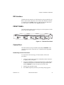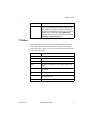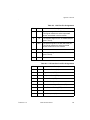
1
T3SU 300 User Manual
1202217L1
1200218L1
1200219L1
1200284L1
1202217L2
1202217L4
DC Version Including AC Mains Power Supply
HSSI DTE Interface Card
V.35 DTE Interface Card
Quad DSX-1 Interface Card
AC Version
DC Version
61202217L1-1A
September 2002
61202217L1-1A
T3SU 300 User Manual
1
Trademark Information:
OpenView is a trademark of Hewlett-Packard Company.
Spectrum is a registered trademark of Cabletron.
Netview is a registered trademark of IBM.
901 Explorer Boulevard
P.O. Box 140000
Huntsville, AL 35814-4000
(256) 963-8000
© 2002 ADTRAN, Inc.
All Rights Reserved.
Printed in U.S.A.
2
T3SU 300 User Manual
61202217L1-1A
About this Manual
This manual is arranged so you can quickly and easily find the information you need.
The following is an overview of the contents of this manual:
•
Chapter 1, Introduction, familiarizes you with fiber networks and T3SU 300 highlights and gives a brief explanation of the option cards that may be purchased for
use with the T3SU 300.
•
Chapter 2, Installation and Operation, describes the T3SU 300 connectors (pin
assignments are given in Appendix A), provides installation instructions, and
explains how to operate your T3SU 300 using the terminal interface.
•
Chapter 3, Configuration, explains how to access the T3SU 300 Configuration
menu, describes selections made in the Configuration menus, and provides a
menu tree of Configuration options.
•
Chapter 4, Status, describes each field of the Status menu.
•
Chapter 5, Statistics, explains how to access statistical information for the T3SU
300 and describes each field.
•
Chapter 6, Diagnostics, explains how to diagnose problems using loopback and
BERT tests.
•
Appendix A provides pinouts for the T3SU 300 connectors.
•
Appendix B contains product specifications.
•
Appendix C lists the acronyms and abbreviations used in this document.
•
Appendix D is a glossary.
61202217L1-1A
T3SU 300 User Manual
3
Notes provide additional useful information.
Cautions signify information that could prevent service interruption.
Warnings provide information that could prevent damage to the
equipment or endangerment to human life.
Safety Instructions
When using your telephone equipment, please follow these basic safety precautions to
reduce the risk of fire, electrical shock, or personal injury:
1. Do not use this product near water, such as a bathtub, wash bowl, kitchen
sink, laundry tub, in a wet basement, or near a swimming pool.
2. Avoid using a telephone (other than a cordless-type) during an electrical
storm. There is a remote risk of shock from lightning.
3. Do not use the telephone to report a gas leak in the vicinity of the leak.
4. Use only the power cord, power supply, and/or batteries indicated in the
manual. Do not dispose of batteries in a fire. They may explode. Check with
local codes for special disposal instructions.
Save These Important Safety Instructions
4
T3SU 300 User Manual
61202217L1-1A
Affidavit Requirements for Connection to Digital Services
•
•
•
An affidavit is required to be given to the telephone company whenever digital
terminal equipment without encoded analog content and billing protection is used
to transmit digital signals containing encoded analog content which are intended
for eventual conversion into voiceband analog signals and transmitted on the
network.
The affidavit shall affirm that either no encoded analog content or billing
information is being transmitted or that the output of the device meets Part 68
encoded analog content or billing protection specifications.
End user/customer will be responsible for filing an affidavit with the local
exchange carrier when connecting unprotected customer premise equipment (CPE)
to 1.544 Mbps or subrate digital services.
Until such time as subrate digital terminal equipment is registered for voice
applications, the affidavit requirement for subrate services is waived.
61202217L1-1A
T3SU 300 User Manual
5
Affidavit for Connection of Customer Premises Equipment
to 1.544 Mbps and/or Subrate Digital Services
For the work to be performed in the certified territory of ___________________
(telco name)
State of ________________
County of ________________
I, _______________________ (name), ____________________________________
(business address),
____________________ (telephone number) being duly sworn, state:
I have responsibility for the operation and maintenance of the terminal
equipment to be connected to 1.544 Mbps and/or ________ subrate digital
services. The terminal equipment to be connected complies with Part 68 of the
FCC rules except for the encoded analog content and billing protection
specifications. With respect to encoded analog content and billing protection:
( ) I attest that all operations associated with the establishment, maintenance, and
adjustment of the digital CPE with respect to analog content and encoded billing
protection information continuously complies with Part 68 of the FCC Rules and
Regulations.
( ) The digital CPE does not transmit digital signals containing encoded analog
content or billing information which is intended to be decoded within the
telecommunications network.
( ) The encoded analog content and billing protection is factory set and is not under
the control of the customer.
I attest that the operator(s)/maintainer(s) of the digital CPE responsible for the
establishment, maintenance, and adjustment of the encoded analog content and
billing information has (have) been trained to perform these functions by
successfully having completed one of the following (check appropriate blocks):
6
T3SU 300 User Manual
61202217L1-1A
( ) E. A training course provided by the manufacturer/grantee of the equipment
used to encode analog signals; or
( ) F. A training course provided by the customer or authorized representative,
using training materials and instructions provided by the manufacturer/
grantee of the equipment used to encode analog signals; or
( ) G. An independent training course (e.g., trade school or technical institution)
recognized by the manufacturer/grantee of the equipment used to encode
analog signals; or
( ) H. In lieu of the preceding training requirements, the operator(s)/maintainer(s) is
(are) under the control of a supervisor trained in accordance with _________
(circle one) above.
I agree to provide ______________________ (telco’s name) with proper
documentation to demonstrate compliance with the information as provided in
the preceding paragraph, if so requested.
_________________________________Signature
_________________________________Title
_________________________________ Date
Transcribed and sworn to before me
This ________ day of _______________, _______
_________________________________
Notary Public
My commission expires:
_________________________________
61202217L1-1A
T3SU 300 User Manual
7
FCC regulations require that the following information be provided in this manual:
1. This equipment complies with Part 68 of FCC rules. On the back of the
equipment housing is a label showing the FCC registration number and ringer
equivalence number (REN). If requested, provide this information to the
telephone company.
2. If this equipment causes harm to the telephone network, the telephone
company may temporarily discontinue service. If possible, advance
notification is given; otherwise, notification is given as soon as possible. The
telephone company will advise the customer of the right to file a complaint
with the FCC.
3. The telephone company may make changes in its facilities, equipment,
operations, or procedures that could affect the proper operation of this
equipment. Advance notification and the opportunity to maintain
uninterrupted service are given.
4. If experiencing difficulty with this equipment, please contact ADTRAN for
repair and warranty information. The telephone company may require this
equipment to be disconnected from the network until the problem is corrected
or it is certain the equipment is not malfunctioning.
5. This unit contains no user-serviceable parts.
6. An FCC compliant telephone cord with a modular plug is provided with this
equipment. This equipment is designed to be connected to the telephone
network or premises wiring using an FCC compatible modular jack, which is
Part 68 compliant.
7. The following information may be required when applying to the local
telephone company for a dial-up line for the V.34 modem:
8
Service Type
REN
FIC
USOC
1.544 Mbps - SF
04DU9-BN
6.0N
RJ-48C
1.544 Mbps - SF and B8ZS
04DU9-DN
6.0N
RJ-48C
1.544 Mbps - ESF
04DU9-1KN
6.0N
RJ-48C
1.544 Mbps - ESF and B8ZS
04DU9-1SN
6.0N
RJ-48C
T3SU 300 User Manual
61202217L1-1A
8. The REN is useful in determining the quantity of devices you may connect to
your telephone line and still have all of those devices ring when your number
is called. In most areas, the sum of the RENs of all devices should not exceed
five. To be certain of the number of devices you may connect to your line as
determined by the REN, call your telephone company to determine the
maximum REN for your calling area.
9. This equipment may not be used on coin service provided by the telephone
company. Connection to party lines is subject to state tariffs. Contact your
state public utility commission or corporation commission for information.
61202217L1-1A
T3SU 300 User Manual
9
Federal Communications Commission Radio Frequency
Interference Statement
This equipment has been tested and found to comply with the limits for a Class A
digital device, pursuant to Part 15 of the FCC Rules. These limits are designed to
provide reasonable protection against harmful interference when the equipment is
operated in a commercial environment. This equipment generates, uses, and can
radiate radio frequency energy and, if not installed and used in accordance with the
instruction manual, may cause harmful interference to radio frequencies. Operation of
this equipment in a residential area is likely to cause harmful interference in which
case the user will be required to correct the interference at his own expense.
Shielded cables must be used with this unit to ensure compliance with
Class A FCC limits.
Changes or modifications to this unit not expressly approved by
the party responsible for compliance could void the user’s
authority to operate the equipment.
10
T3SU 300 User Manual
61202217L1-1A
Industry Canada Compliance Information
Notice: The Industry Canada label applied to the product (identified by the Industry
Canada logo or the “IC:” in front of the certification/registration number) signifies
that the Industry Canada technical specifications were met.
Notice: The Ringer Equivalence Number (REN) for this terminal equipment is
supplied in the documentation or on the product labeling/markings. The REN assigned
to each terminal device indicates the maximum number of terminals that can be
connected to a telephone interface. The termination on an interface may consist of any
combination of devices subject only to the requirement that the sum of the RENs of all
the devices should not exceed five (5).
Canadian Emissions Requirements
This digital apparatus does not exceed the Class A limits for radio noise emissions
from digital apparatus as set out in the interference-causing equipment standard
entitled “Digital Apparatus,” ICES-003 of the Department of Communications.
Cet appareil numérique respecte les limites de bruits radioelectriques applicables aux
appareils numériques de Class A prescrites dans la norme sur le materiel brouilleur:
“Appareils Numériques,” NMB-003 edictee par le ministre des Communications.
61202217L1-1A
T3SU 300 User Manual
11
Warranty and Customer Service
ADTRAN will repair and return this product within 5 years from the date of shipment
if it does not meet its published specifications or fails while in service. For detailed
warranty, repair, and return information refer to the ADTRAN Equipment Warranty
and Repair and Return Policy Procedure.
Return Material Authorization (RMA) is required prior to returning equipment to
ADTRAN.
For service, RMA requests, or further information, contact one of the numbers listed
at the end of this section.
LIMITED PRODUCT WARRANTY
ADTRAN warrants that for 5 years from the date of shipment to Customer, all
products manufactured by ADTRAN will be free from defects in materials and
workmanship. ADTRAN also warrants that products will conform to the applicable
specifications and drawings for such products, as contained in the Product Manual or
in ADTRAN's internal specifications and drawings for such products (which may or
may not be reflected in the Product Manual). This warranty only applies if Customer
gives ADTRAN written notice of defects during the warranty period. Upon such
notice, ADTRAN will, at its option, either repair or replace the defective item. If
ADTRAN is unable, in a reasonable time, to repair or replace any equipment to a
condition as warranted, Customer is entitled to a full refund of the purchase price upon
return of the equipment to ADTRAN. This warranty applies only to the original
purchaser and is not transferable without ADTRAN's express written permission. This
warranty becomes null and void if Customer modifies or alters the equipment in any
way, other than as specifically authorized by ADTRAN.
EXCEPT FOR THE LIMITED WARRANTY DESCRIBED ABOVE, THE
FOREGOING CONSTITUTES THE SOLE AND EXCLUSIVE REMEDY OF THE
CUSTOMER AND THE EXCLUSIVE LIABILITY OF ADTRAN AND IS IN LIEU
OF ANY AND ALL OTHER WARRANTIES (EXPRESSED OR IMPLIED).
ADTRAN SPECIFICALLY DISCLAIMS ALL OTHER WARRANTIES,
INCLUDING (WITHOUT LIMITATION), ALL WARRANTIES OF
MERCHANTABILITY AND FITNESS FOR A PARTICULAR PURPOSE. SOME
STATES DO NOT ALLOW THE EXCLUSION OF IMPLIED WARRANTIES, SO
THIS EXCLUSION MAY NOT APPLY TO CUSTOMER.
12
T3SU 300 User Manual
61202217L1-1A
In no event will ADTRAN or its suppliers be liable to the Customer for any incidental,
special, punitive, exemplary or consequential damages experienced by either the
Customer or a third party (including, but not limited to, loss of data or information,
loss of profits, or loss of use). ADTRAN is not liable for damages for any cause
whatsoever (whether based in contract, tort, or otherwise) in excess of the amount
paid for the item. Some states do not allow the limitation or exclusion of liability for
incidental or consequential damages, so the above limitation or exclusion may not
apply to the Customer.
61202217L1-1A
T3SU 300 User Manual
13
Customer Service, Product Support Information, and Training
ADTRAN will repair and return this product if within 5 years from the date of
shipment the product does not meet its published specification or the product fails
while in service.
A return material authorization (RMA) is required prior to returning equipment to
ADTRAN. For service, RMA requests, training, or more information, use the contact
information given below.
Repair and Return
If you determine that a repair is needed, please contact our Customer and Product
Service (CAPS) department to have an RMA number issued. CAPS should also be
contacted to obtain information regarding equipment currently in house or possible
fees associated with repair.
CAPS Department
(256) 963-8722
Identify the RMA number clearly on the package (below address), and return to the
following address:
ADTRAN Customer and Product Service
901 Explorer Blvd. (East Tower)
Huntsville, Alabama 35806
RMA # _____________
14
T3SU 300 User Manual
61202217L1-1A
Pre-Sales Inquiries and Applications Support
Your reseller should serve as the first point of contact for support. If additional presales support is needed, the ADTRAN Support web site provides a variety of support
services such as a searchable knowledge base, latest product documentation,
application briefs, case studies, and a link to submit a question to an Applications
Engineer. All of this, and more, is available at:
http://support.adtran.com
When needed, further pre-sales assistance is available by calling our Applications
Engineering Department.
Applications Engineering (800) 615-1176
Post-Sale Support
Your reseller should serve as the first point of contact for support. If additional support
is needed, the ADTRAN Support web site provides a variety of support services such
as a searchable knowledge base, updated firmware releases, latest product
documentation, service request ticket generation and trouble-shooting tools. All of
this, and more, is available at:
http://support.adtran.com
When needed, further post-sales assistance is available by calling our Technical
Support Center. Please have your unit serial number available when you call.
Technical Support
61202217L1-1A
(888) 4ADTRAN
T3SU 300 User Manual
15
Installation and Maintenance Support
The ADTRAN Custom Extended Services (ACES) program offers multiple types and
levels of installation and maintenance services which allow you to choose the kind of
assistance you need. This support is available at:
http://www.adtran.com/aces
For questions, call the ACES Help Desk.
ACES Help Desk
(888) 874-ACES (2237)
Training
The Enterprise Network (EN) Technical Training Department offers training on our
most popular products. These courses include overviews on product features and
functions while covering applications of ADTRAN's product lines. ADTRAN
provides a variety of training options, including customized training and courses
taught at our facilities or at your site. For more information about training, please
contact your Territory Manager or the Enterprise Training Coordinator.
16
Training Phone
(800) 615-1176, ext. 7500
Training Fax
(256) 963-6700
Training Email
[email protected]
T3SU 300 User Manual
61202217L1-1A
Table of Contents
List of Figures .......................................................................................................................21
List of Tables .........................................................................................................................23
Chapter 1. Introduction .......................................................................................................25
Product Overview .................................................................................................................25
T3 Overview ...........................................................................................................................26
SNMP ......................................................................................................................................26
TELNET ..................................................................................................................................27
Interface Option Cards .........................................................................................................27
HSSI Card.........................................................................................................................28
V.35 Card..........................................................................................................................28
Quad DSX-1 Card ...........................................................................................................28
Chapter 2. Installation and Operation .............................................................................31
Receiving Inspection .............................................................................................................31
ADTRAN Shipments Include........................................................................................31
Customer Provides .........................................................................................................32
Power Up..........................................................................................................................32
Installing the Unit ..................................................................................................................33
Rackmount Installation ..................................................................................................33
Desktop Installation........................................................................................................34
Rear Panel ...............................................................................................................................34
DTE Port Interface Card Slots .......................................................................................35
Alarm Connector.............................................................................................................36
DTE Port 1 (HSSI Interface) ...........................................................................................36
Auxiliary Port ..................................................................................................................36
LAN Port ..........................................................................................................................36
DS3 Interface....................................................................................................................37
Front Panel .............................................................................................................................37
61202217L1-1A
T3SU 300 User Manual
17
Table of Contents
Control Port..................................................................................................................... 37
LED Descriptions ........................................................................................................... 40
Chapter 3. Configuration ................................................................................................... 43
DS3 Network ......................................................................................................................... 44
DS3 Framing ................................................................................................................... 45
Line Length ..................................................................................................................... 45
DS3 Timing...................................................................................................................... 45
DS3 Scrambler................................................................................................................. 46
Multiplexing Mode ........................................................................................................ 46
Data Link ......................................................................................................................... 46
Remote Auto-Configuration......................................................................................... 46
DTE Ports ............................................................................................................................... 46
Port Selections 1-4 .......................................................................................................... 47
Timed Profiles................................................................................................................. 54
System Management ............................................................................................................ 55
Local IP Address ............................................................................................................ 56
Subnet Mask.................................................................................................................... 56
Gateway IP Address ...................................................................................................... 56
Remote IP Address......................................................................................................... 57
IP Security ....................................................................................................................... 57
IP Hosts............................................................................................................................ 57
Management Port ........................................................................................................... 57
Modem Mode ................................................................................................................. 57
Modem Baud Rate.......................................................................................................... 58
Read Community Name ............................................................................................... 58
Write Community Name .............................................................................................. 58
Trap IP Addresses .......................................................................................................... 58
Trap Generation ............................................................................................................. 58
Password ......................................................................................................................... 62
Unit ID ............................................................................................................................. 62
Terminal Timeout........................................................................................................... 62
Date/Time ....................................................................................................................... 62
Alarm Relay .................................................................................................................... 62
Dialup Options ............................................................................................................... 62
Utilities ................................................................................................................................... 65
Save Configuration ............................................................................................................... 66
Chapter 4. Status67
Network Port ......................................................................................................................... 67
DS3 Framing ................................................................................................................... 67
18
T3SU 300 User Manual
61202217L1-1A
Table of Contents
Network State ..................................................................................................................68
Alarm State ......................................................................................................................68
Data Link State ................................................................................................................69
Remote State ....................................................................................................................69
DTE Ports ................................................................................................................................70
Interface Type ..................................................................................................................70
Port Status ........................................................................................................................70
T1 Status ...........................................................................................................................71
Bandwidth........................................................................................................................72
DTE Leads ........................................................................................................................72
Chapter 5. Statistics..............................................................................................................75
Viewing Statistical information ...........................................................................................75
Alarm History..................................................................................................................76
Performance Parameters ................................................................................................78
Chapter 6. Diagnostics ........................................................................................................83
DS3 ....................................................................................................................................85
DTE Ports 1-4 ...................................................................................................................87
BERT Configuration .......................................................................................................97
Chapter 7. Applications ......................................................................................................99
Single Port Full T3 Bandwidth ............................................................................................99
Point-to-Point Multiport Application ..............................................................................100
Fractional T3 Carrier Application .....................................................................................102
Remote SNMP Management Application .......................................................................104
Voice Application ................................................................................................................105
Appendix A. Pinouts .........................................................................................................107
Appendix B. Specifications Summary ...........................................................................111
Appendix C. Acronyms/Abbreviations..........................................................................113
Appendix D. Glossary .......................................................................................................117
Index .....................................................................................................................................129
61202217L1-1A
T3SU 300 User Manual
19
Table of Contents
20
T3SU 300 User Manual
61202217L1-1A
List of Figures
Figure 2-1. DC Power Connector .......................................................................................33
Figure 2-2. T3SU 300 Rear View (AC Version) .................................................................35
Figure 2-3. T3SU 300 Front Panel .......................................................................................37
Figure 2-4. Terminal Main Menu........................................................................................38
Figure 3-1. Configuration Main Menu ..............................................................................44
Figure 3-2. DS3 Network Configuration Menu................................................................45
Figure 3-3. DTE Ports Menu ...............................................................................................47
Figure 3-4. Port Configuration Menu (V.35 Interface Card)...........................................48
Figure 3-5. Port Configuration Menu (Quad DSX-1 Interface Card) ............................52
Figure 3-6. Timed Profiles Screen .......................................................................................54
Figure 3-7. Example of a Profile Configuration Menu ....................................................55
Figure 3-8. System Management Configuration Menu ..................................................56
Figure 3-9. Trap Generation Menu.....................................................................................59
Figure 3-10. Dialup Options Menu ......................................................................................63
Figure 3-11. System Utilities Menu ......................................................................................66
Figure 4-1. Status Menu .......................................................................................................67
Figure 5-1. Main Local Statistics Menu Screen.................................................................76
Figure 5-2. Current Alarm Count Screen ..........................................................................77
Figure 5-3. 24-Hour Alarm History Screen .......................................................................77
Figure 5-4. Quad DSX-1 24-Hour Alarm History ............................................................78
Figure 5-5. Network Statistics Menu for Current 15-Minute Interval ..........................79
Figure 5-6. Network Port Statistics 24-Hour History Screen .........................................80
Figure 5-7. Network Port Statistics Menu (24-Hour Totals) ...........................................81
61202217L1-1A
T3SU 300 User Manual
21
List of Figures
Figure 6-1. Diagnostics Main Menu .................................................................................. 84
Figure 6-2. DS3 Diagnostics Menu .................................................................................... 85
Figure 6-3. DS3 Payload Loopback Test ........................................................................... 86
Figure 6-4. Line Loopback Test .......................................................................................... 86
Figure 6-5. HSSI or V.35 Port Diagnostics Menu............................................................. 88
Figure 6-6. Payload Loopback Test ................................................................................... 89
Figure 6-7. Payload BERT Test ........................................................................................... 89
Figure 6-8. DTE Loopback Test.......................................................................................... 90
Figure 6-9. Payload and DTE Loopback Test................................................................... 90
Figure 6-10. Quad DSX-1 Diagnostics Menu ..................................................................... 91
Figure 6-11. T1 Payload Loopback Test .............................................................................. 92
Figure 6-12. Framer Loopback Test ..................................................................................... 92
Figure 6-13. T1 Local Loopback Test................................................................................... 93
Figure 6-14. Line Loopback Test .......................................................................................... 93
Figure 6-15. Payload Loopback Test ................................................................................... 94
Figure 6-16. DTE Loopback Test.......................................................................................... 95
Figure 6-17. Payload and DTE Loopback Test................................................................... 96
Figure 6-18. T1 Payload Loopback Test .............................................................................. 96
Figure 6-19. BERT Pattern Menu ......................................................................................... 97
Figure 7-1. Single Port Application ................................................................................... 99
Figure 7-2. Multiport Application ................................................................................... 101
Figure 7-3. Fractional Application................................................................................... 103
Figure 7-4. Remote Management Application .............................................................. 104
Figure 7-5. Voice Application ........................................................................................... 105
22
T3SU 300 User Manual
61202217L1-1A
List of Tables
Table 3-1.
HSSI and V.35 Configuration Selections ......................................................49
Table 3-2.
Additional V.35 Interface Port Configuration Selections ..........................50
Table 3-3.
DSX-1 Interface Port Configuration Selections ...........................................52
Table 3-4.
Near End Alarm Trap Descriptions ..............................................................59
Table 3-5.
Far End Alarm Trap Descriptions .................................................................60
Table 3-6.
MIB II Standard Trap Descriptions ...............................................................61
Table 3-7.
Network Trap Descriptions ...........................................................................61
Table 3-8.
DTE Port Trap Description .............................................................................61
Table 3-9.
Quad DSX Port Trap Description ..................................................................61
Table 4-1.
LA and LB Leads .............................................................................................73
Table 4-2.
V.35 Interface Leads ........................................................................................74
Table 7-1.
Single Port Full T3 Bandwidth Application Configuration Example ....100
Table 7-2.
Multiport Application Configuration Example ........................................101
Table 7-3.
Configuration Example for Fractional T3 Application ............................103
Table 7-4.
Configuration Example for Remote SNMP Management Application .104
Table 7-5.
Configuration Example for a Voice Application ......................................105
Table A-1. Control Port Pin Assignments .....................................................................107
Table A-2. HSSI Interface Pin Assignments ..................................................................108
Table A-3. LAN Port Pin Assignments ..........................................................................109
Table A-4. V.35 Interface Card Pin Assignments .........................................................109
Table A-5. Quad DSX-1 Interface Card Pin Assignments ...........................................110
61202217L1-1A
T3SU 300 User Manual
23
List of Tables
24
T3SU 300 User Manual
61202217L1-1A
Chapter 1
Introduction
PRODUCT OVERVIEW
The T3SU 300 is a multiport DSU/CSU (data service unit/channel
service unit) that provides access to T3 services. The unit provides a
cost-effective, versatile approach for migrating T1 services to T3.
The TDM (time division multiplexer) multiport design allows you
to share the cost of a T3 line between multiple applications. This
unit maximizes the use of T3 services, providing up to four data
ports capable of transmitting and receiving high-capacity, real time
data.
A HSSI (high speed serial interface) port is built in along with three
slots which accept additional HSSI, V.35, or Quad DSX-1 interface
cards. The HSSI interfaces support rates between 75 kbps and
44.2 Mbps in 75 kbps increments. The high speed V.35 interface
option supports rates up to 10 Mbps in increments of 75 kbps. The
Quad DSX-1 interface card provides four DSX-1 lines. Each DSX-1
port supports rates up to 1.544 Mbps.
Embedded SNMP (simple network management protocol) and
TELNET are available through either a SLIP/PPP or a 10BaseT
Ethernet port. Through the Management Information Base II (MIB
II), RFC 1407 standards, and an ADTRAN enterprise MIB, the
T3SU 300 can be configured, monitored, and diagnosed using
standard SNMP network management programs such as Hewlett
Packard’s HP OpenView™, IBM’s Netview™, and Cabletron’s
Spectrum™.
61202217L1-1A
T3SU 300 User Manual
25
Chapter 1. Introduction
Complete configuration, diagnostics, and performance monitoring
are available through SNMP, TELNET, or a VT100 terminal
interface. This connection can be made via Ethernet, a local EIA232 link, or through the built-in V.34 modem. Advanced dial-out
on trap capabilities through the built-in modem allow the T3SU 300
to contact remote hosts and alert them to DSX-3 network conditions
(without dedicated management connections). The T3SU 300 is
designed for either desktop use or installation in a 19-inch rack.
The major features or the T3SU 300 are as follows:
•
Full feature multiport T3 DSU/CSU
•
Maximum of four user data ports: one integrated HSSI port
and three additional slots for optional HSSI, high speed V.35, or
Quad DSX-1 cards
•
Automatic or manual remote configuration
•
Embedded SNMP and TELNET management through 10BaseT
Ethernet or SLIP/PPP
•
Detailed performance monitoring for local and remote units
•
Simplified configuration through detailed VT100 terminal
menu structure
•
Integrated V.34 modem for dial-up and dial-out access
•
Standard 5-year warranty
T3 OVERVIEW
T3 provides the same bandwidth as 28 T1s and is used to
interconnect high-speed bridges, routers, front-end processors, and
data terminal equipment (DTE). T3 service plays a major role in
Internet backbones and public organizations needing broad
bandwidth for WAN (wide area network) connectivity.
SNMP
The T3SU 300's embedded SNMP feature allows the unit to be
accessed and controlled by a network manager through either the
auxiliary (AUX) control port or the 10BaseT local area network
26
T3SU 300 User Manual
61202217L1-1A
Chapter 1. Introduction
(LAN) port. The T3SU 300 supports the MIB-II standard, RFC 1213,
and the ADTRAN Enterprise Specific MIB.
MIB files are available from ADTRAN in the support section of the ADTRAN web page at www.adtran.com.
The term SNMP broadly refers to the message protocols used to
exchange information between the network management system
(NMS) and the managed devices, as well as to the structure of
device management databases. SNMP has three basic components:
Network Manager
Control programs that collect, control, and present data pertinent to
the operation of the network devices. These programs reside on a
network management station.
Agent
Control program that resides in every network device. This
program responds to queries and commands from the network
manager, returns requested information or invokes configuration
changes initiated by the manager, and sends unsolicited traps to the
manager.
MIB
Industry standard presentation of all status and configuration
parameters supported by a network device.
TELNET
TELNET provides a password-protected, remote login facility to
the T3SU 300 that allows a remote user to control the T3SU 300
through the terminal menus. Only one TELNET session may be
active at a time.
INTERFACE OPTION CARDS
Optional interface cards may be purchased to equip the T3SU 300
with up to three additional ports. HSSI, V.35, and Quad DSX-1
interface cards are available.
61202217L1-1A
T3SU 300 User Manual
27
Chapter 1. Introduction
HSSI Card
The optional HSSI card plugs into one of the three card slots on the
rear of the T3SU 300. With optional HSSI cards installed, the total
44.2 Mbps bandwidth of the T3 can be divided among the total
number of ports to provide multiple data channels over the T3. The
total bandwidth of the T3 can be divided among the available ports
in any fashion, as long as the divisions are on 75 kbps boundaries.
The HSSI card can be hot inserted or swapped. When it is inserted
in a slot on the rear panel and its faceplate is secured to the rear
panel of the T3SU 300 with the integral thumb screws, a PCMCIA
type connector on the card mates with a compatible connector on
the main board of the T3SU 300. A standard 50-pin HSSI connector
is then available for DTE connections. See the section DTE Port
Interface Card Slots on page 35 for more information on installing
option cards.
V.35 Card
The optional V.35 card plugs into the card slots on the rear of the
T3SU 300 to provide a V.35-type DTE interface. Operation of the
V.35 card is similar to that of the HSSI card except that the
maximum bandwidth of the V.35 card is limited to 10 Mbps.
Like the HSSI card, the V.35 card can be hot inserted or swapped,
and it installs just as the HSSI card does. Instead of the standard
HSSI connector, this card contains a standard 34-pin V.35 connector
for DTE connections. See the section DTE Port Interface Card Slots on
page 35 for more information on installing option cards.
Quad DSX-1 Card
The optional Quad DSX-1 interface card plugs into the card slots on
the rear of the T3SU 300. This card allows you to transport up to
four DSX-1 lines per card over the DS3 interface of the T3SU 300
along with high-speed data from the other HSSI/V.35 ports. This
configuration allows connectivity of both voice channels and highspeed data channels for two point-to-point sites using only one
28
T3SU 300 User Manual
61202217L1-1A
Chapter 1. Introduction
network interface. Up to three cards may be installed into any of
the T3SU 300 DTE port card slots.
Even though the Quad DSX-1 interface card allows you to transport T1
information, the T3SU 300 still operates the DS3 interface in an unchannelized fashion. Therefore, your DS3 network provider must supply you
with an unchannelized, point-to-point DS3.
61202217L1-1A
T3SU 300 User Manual
29
Chapter 1. Introduction
30
T3SU 300 User Manual
61202217L1-1A
Chapter 2
Installation and Operation
RECEIVING INSPECTION
Carefully inspect the T3SU 300 for any damage that may have
occurred in shipment. If damage is suspected, file a claim
immediately with the carrier and contact ADTRAN Technical
Support (see the front section of this manual for contact
information). Keep the original shipping container to use for future
shipment or verification of damage during shipment.
ADTRAN Shipments Include
The following items are included in ADTRAN shipments of the
T3SU 300:
61202217L1-1A
•
T3SU 300 unit
•
User manual
•
An 8-position modular to 8-position modular cable
(part number: 3127004)
•
An 8-position modular to DB-25 female connector
(part number: 3196ADPT005)
•
A 4-position modular to 4-position modular cable
(part number: 3127014)
•
Two BNC to BNC coaxial cables (part number: 3125I054)
•
Mounting ears for 19-inch rack installation
T3SU 300 User Manual
31
Chapter 2. Installation and Operation
•
Rubber feet for stand-alone use
The ADTRAN T3SU 300 MIB is available in the support section of the
ADTRAN web page at www.adtran.com.
Customer Provides
The customer provides an interface cable for each port used. Each
cable should be either HSSI, V.35, or an 8-pin modular cable,
depending on the interface type.
Power Up
The AC version of the T3SU 300 is provided with a captive eightfoot power cord, terminated by a three-prong plug which connects
to a grounded 115 VAC power receptacle.
Power to the AC version of the T3SU 300 must be provided from a
grounded 115 VAC, 60 Hz receptacle.
A three-position terminal block which accommodates 12 to 26
AWG wire is located on the rear panel of the T3SU 300 DC version.
The positive (+) and negative (-) terminals connect to a 24 to
48 VDC, 0.4A power source. Figure 2-1 on page 33 provides an
illustration of the terminal block power connector, along with
definitions for the three connector symbols.
The chassis should be connected to an earth ground.
32
T3SU 300 User Manual
61202217L1-1A
Chapter 2. Installation and Operation
Symbol
Definition
Frame ground.
+
Positive side of DC power source
(usually ground).
-
Negative side of DC power source
(usually -48V).
Figure 2-1. DC Power Connector
The following UL requirements must be met during installation of
the DC version of the T3SU 300:
1.
The unit must be connected to a reliably grounded -24 or -48
VDC source which is electrically isolated from the AC source.
2.
The branch circuit overcurrent protection should be a fuse or
circuit breaker rated 48 V, 15 A.
3.
The unit should be installed in accordance with the
requirements of NEC NFPA 70.
4.
A readily accessible disconnect device that is suitably approved
and rated should be incorporated in the fixed wiring.
INSTALLING THE UNIT
The T3SU 300 can be used as a desktop stand-alone device or
mounted into a standard 19-inch equipment rack. See Establishing
Terminal Connection on page 37 for information on terminal
configuration.
Rackmount Installation
Follow these steps to mount your unit into a rack:
1.
61202217L1-1A
Install the 19-inch rackmount flanges on each side of the
T3SU 300 enclosure at one of the three available positions.
T3SU 300 User Manual
33
Chapter 2. Installation and Operation
Be sure to install the flanges with the screw provided.
2.
After the flanges have been installed, position the T3SU 300 at
the correct location within the rack and secure the mounting
flanges to the mounting rails of the rack.
3.
Make all network, DTE, and power connections to the rear of
the unit. See Power Up on page 32 for more information on
making the DC power connection.
4.
Using the 8-position modular to DB-25 female connector and
the 8-position modular to 8-position modular cable, connect a
VT100 terminal device to the CONTROL interface jack on the
front panel of the unit.
Desktop Installation
Follow these steps when using your T3SU 300 as a desktop unit:
1.
Affix the four adhesive-backed rubber feet to the bottom of the
unit, one in each of the four corners. The feet should be placed
approximately one inch from the front or back and one inch
from the sides of the unit
2.
Make all network, DTE, and power connections to the rear of
the unit. See Power Up on page 32 for more information on
making the DC power connection.
3.
Using the 8-position modular to DB-25 female connector and
the 8-position modular to 8-position modular cable, connect a
VT100 terminal device to the CONTROL interface jack on the
front panel of the unit.
REAR PANEL
The T3SU 300 is equipped with three option card slots, a built-in
HSSI interface, an alarm output terminal block, an auxiliary (AUX)
port, a LAN port, and a DS3 interface. Pin assignments for
34
T3SU 300 User Manual
61202217L1-1A
Chapter 2. Installation and Operation
connectors are given in Appendix A, Pinouts on page 107. The
T3SU 300 rear panel is shown in Figure 2-2.
NN
DD
Z
V
JJ
LL
DS3 INTERFACE
KK
R
L
F
V.35 INTERFACE
DTE PORT 3
DTE PORT 4
NC COM NO
MM
HH
EE
CC
FF
BB
Y
AA
J
T
X
D
N
P
K
E
A
U
S
H
C
M
W
B
AUX
ALARM
HSSI INTERFACE
DTE PORT 2
LAN
RX IN
TX OUT
DTE PORT 1
Item
Function
On/Off Switch
On/Off control
115 VAC Connection
Power connection (AC version)
DTE Ports 2-4
Interface option card slots
Alarm
NC/NO relay contacts
DTE Port 1
Integral HSSI interface
Aux
Telephone line connection for internal V.34 modem
LAN
10BaseT LAN connection
DS3 Interface
T3 service connection
Figure 2-2. T3SU 300 Rear View (AC Version)
DTE Port Interface Card Slots
The T3SU 300 rear panel has three card slots for the installation of
optional interface cards. To insert cards, perform the following
procedure:
61202217L1-1A
1.
Remove blank slot cover from the rear of the T3SU 300.
2.
Slide the card into the corresponding rear slot until the card
panel is flush with the T3SU 300 chassis.
3.
Push in thumbscrews and turn clockwise to secure the card and
ensure proper connection to the main board of the T3SU 300.
T3SU 300 User Manual
35
Chapter 2. Installation and Operation
Alarm Connector
The alarm connector is a three-position, screw-type terminal block
that is connected to the three contacts of a Form C-type relay on the
main board of the T3SU 300. This relay is activated any time the
T3SU 300 detects an alarm condition on the T3 network interface.
The alarm function can be disabled through the A LARM RELAY
selection of the CONFIGURATION menu.
DTE Port 1 (HSSI Interface)
DTE port 1 is a built-in HSSI port that resides on the main board of
the T3SU 300. The bandwidth of this port is configurable from
75 kbps to 44.2 Mbps in either 75 kbps or 3.16 Mbps increments.
When a single application requires the full 44.2 Mbps of
bandwidth, the T3SU 300 does not have to be equipped with
additional port cards.
Auxiliary Port
The auxiliary (AUX) port is an 8-pin modular jack located on the
rear panel of the T3SU 300. The AUX port provides a telephone line
(POTS) connection for the internal V.34 modem.
The T3SU 300 can be configured as a dial-in host and also as a dialout-on-TRAP device (meaning that the unit dials out to a specified
host to report error conditions). Configure the modem parameters
in the DIALUP OPTIONS menu under the SYSTEM MANAGEMENT
portion of the CONFIGURATION menu (CONFIGURATION -> SYSTEM
MANAGEMENT -> DIALUP OPTIONS).
LAN Port
The LAN port is an 8-pin modular connector that provides a
10BaseT Ethernet LAN interface. This LAN interface is used for
SNMP and TELNET control.
36
T3SU 300 User Manual
61202217L1-1A
Chapter 2. Installation and Operation
DS3 Interface
The DS3 network interface is a full-duplex circuit provided by two
BNC coaxial cable connections. The receive data from the network
is connected to the RX IN connector, while the transmit data from
the T3SU 300 is connected to the TX OUT connector.
FRONT PANEL
The T3SU 300 faceplate is shown in Figure 2-3. Descriptions of each
part of the front panel follow.
Figure 2-3. T3SU 300 Front Panel
Control Port
The T3SU 300 has an 8-pin modular jack labeled CONTROL. The
control port provides connection to a VT100 EIA-232 compatible
interface.
Establishing Terminal Connection
To control the T3SU 300 using a VT100 terminal, follow this
procedure:
61202217L1-1A
1.
Configure the VT100 terminal for 57600 baud, 8-bit characters,
no parity, and one stop bit.
2.
Using the ADTRAN-provided terminal interface cable adapter,
connect the DTE port of a terminal to the 8-pin modular jack
labeled CONTROL on the front panel of the T3SU 300.
3.
Initialize the terminal session.
4.
Press Enter repeatedly until the password prompt appears.
T3SU 300 User Manual
37
Chapter 2. Installation and Operation
5.
Enter the password. The factory default password is adtran (all
lower-case). The MAIN menu appears. See Figure 2-4 on page
38.
6.
Make selections by entering the number corresponding to the
chosen parameter. Press ESC to return to the previous screen.
End a terminal session by selecting LOGOUT from the MAIN
menu or by pressing Ctl-C at any time.
Figure 2-4. Terminal Main Menu
Navigating Within the Menus
Navigate within the T3SU 300 terminal menus using the following
procedures:
If you want to...
Press...
select an item
the number corresponding to your choice, and
then press the Enter key.
scroll between screens
within the same
selection
the up and down arrow keys. Additional screens
are available when UP or DOWN is displayed in
the right-hand side of the menu.
scroll left and right
the left and right arrow keys. Additional screens
within the same screen are available when < or > is displayed in the top
portion of the menu.
38
T3SU 300 User Manual
61202217L1-1A
Chapter 2. Installation and Operation
If you want to...
Press...
return to the previous
menu
the ESC key.
end the terminal
session
Ctl-C.
refresh the display
Ctl-R.
Menus Available
Status
This selection provides status information on the network and DTE
ports. See Chapter 4, Status on page 67 for more information.
Statistics
This selection provides statistical information for the network and
DTE ports. See Chapter 5, Statistics on page 75 for more
information.
Configuration
The CONFIGURATION menu is used to set network, DTE, and system
management parameters. See Chapter 3, Configuration on page 43
for more detailed information.
Diagnostics
The DIAGNOSTICS menu is used to perform loopback and BERT
tests. See Chapter 6, Diagnostics on page 83 for more detailed
information.
Remote Login
The REMOTE LOGIN selection allows you to configure the remote
T3SU 300. The remote unit’s password is required at login. The
D ATA LINK option (in the DS3 NETWORK CONFIGURATION menu)
must be enabled in order to perform remote configuration.
Logout
The LOGOUT selection ends the terminal session and logs out of the
system. Password entry is required before a new session can begin.
61202217L1-1A
T3SU 300 User Manual
39
Chapter 2. Installation and Operation
LED Descriptions
The T3SU 300 has LED status indicators for remote access, the
network port, and for each individual DTE port. These LEDs are
identified as follows:
Remote Active
This LED is solid when a remote configuration session is taking
place through a TELNET session or from the remote end T3SU 300.
It flashes when the unit is being accessed locally through the front
panel CONTROL port.
Network LEDs
In Service
This LED is active when a valid signal is being received on the DS3
interface.
In Test
This LED is active when the network interface has been put in
loopback by the service provider.
Alarm
This LED is active when the DS3 receive signal contains framing
errors, the yellow alarm is received from the far end unit, or other
alarm messages are received from the network.
LOS
This LED is active when no receive signal from the network is
detected on the Rx (in) circuit.
40
T3SU 300 User Manual
61202217L1-1A
Chapter 2. Installation and Operation
DTE Port LEDs
Status
This LED indicates the following conditions:
LED
Condition
Off
No option card is installed.
Flashing green
Interface is available but not configured.
On green
Interface is available and configured.
On red
DTE fault condition (for HSSI interface, no clock
from DTE).
On yellow
For HSSI interface, terminal available (TA)
signal inactive.
In Test
This LED is active when the DTE interface is in a loopback
condition or is performing a BERT test.
TD
This LED is active when the T3SU 300 DTE port is transmitting
data.
RD
This LED is active when the T3SU 300 DTE port is receiving data.
61202217L1-1A
T3SU 300 User Manual
41
Chapter 2. Installation and Operation
42
T3SU 300 User Manual
61202217L1-1A
Chapter 3
Configuration
The T3SU 300 can be configured locally and remotely. Local
configuration is accomplished through a 10BaseT Ethernet
connection, a SLIP/PPP port, or a VT100 terminal. Remote
configuration can take place through the T3 datalink using a local
T3SU 300.
The CONFIGURATION menu (see Figure 3-1 on page 44) consists of
the following submenus relating to specific interfaces or functions:
DS3 NETWORK
DTE PORTS
SYSTEM MANAGEMENT
U TILITIES
SAVE CONFIGURATION
Detailed descriptions of each individual menu parameter are given
in the following sections. These sections are divided by the five
submenus: DS3 NETWORK (page 44), DTE PORTS (page 46), SYSTEM
MANAGEMENT (page 55), UTILITIES (page 65), and SAVE
C ONFIGURATION (page 66).
61202217L1-1A
T3SU 300 User Manual
43
Chapter 3. Configuration
Figure 3-1. Configuration Main Menu
DS3 NETWORK
Select 1 DS3 NETWORK to access the network configuration
parameters. Configure the T3SU 300 network settings to match the
T3 signal received from the service provider. During remote
configuration, this menu is read-only. The DS3 N ETWORK
C ONFIGURATION menu is shown in Figure 3-2 on page 45.
Descriptions of the DS3 NETWORK fields follow the figure.
44
T3SU 300 User Manual
61202217L1-1A
Chapter 3. Configuration
Figure 3-2. DS3 Network Configuration Menu
DS3 Framing
Set the framing format to match the format of the receive signal at
the network interface. C-BIT PARITY and M13 framing formats are
supported. Select AUTO to allow the interface to detect the framing
type automatically.
Line Length
Set the line length to reflect the physical length of the DS3 network
line. Set to LONG if the cabling distance exceeds 225 feet; set to
SHORT if the distance is less than 225 feet.
DS3 Timing
Set the timing to LOOP if the T3SU 300 is to derive timing from the
network; set to LOCAL if the unit is to be the master timing source
for the circuit. In most cases, the unit should be configured for
LOOP timing.
61202217L1-1A
T3SU 300 User Manual
45
Chapter 3. Configuration
DS3 Scrambler
Enable this option to scramble the DS3 payload data. This prevents
certain transport equipment from falsely reporting alarms.
Multiplexing Mode
The MULTIPLEXING MODE menu allows you to select the DTE port
bandwidth increment size. The increment size of Nx75 kbps allows
the user to divide 588 blocks among the four ports. The increment
size of Nx3.16 Mbps has 14 blocks available, and ports 2, 3, and 4
are disabled. Only port 1, the built-in HSSI port, is available in this
mode. The Nx3.16 Mbps mode provides compatibility with Juniper
and Cisco routers at below full-bandwidth rates. When the user
switches the multiplexing mode, the system will reboot causing
service interruption. Loading default settings does not reset this
option.
Data Link
Set to ENABLE to allow for remote configuration. When enabled, the
T3SU 300 provides a channel between the local and the remote DSU
for point-to-point remote configuration.
Remote Auto-Configuration
This feature allows one T3SU 300 (set to MASTER) to automatically
relay its DTE port bandwidth configuration to a second unit (set to
SLAVE). If desired, the feature can be disabled by either unit.
DTE PORTS
The DTE PORTS menu allows you to select a port to configure. If
R EMOTE A UTO C ONFIGURATION is set to MASTER (CONFIGURATION ->
DS3 NETWORK -> REMOTE AUTO CONFIGURATION -> MASTER), then
a fifth option, TIMED PROFILES, is available. See Figure 3-3 on page
47. This option allows you to set up timed profiles specifying
bandwidth allocation for all four ports.
46
T3SU 300 User Manual
61202217L1-1A
Chapter 3. Configuration
Configuration selections for the individual ports are described in
the following section. A more in-depth description of TIMED
PROFILES is on page 54.
Figure 3-3. DTE Ports Menu
Port Selections 1-4
Select DTE PORT 1, 2, 3, or 4 to access the port configuration
parameters. Configure each DTE port to be compatible with the
DTE equipment attached to it. PORT CONFIGURATION menu
examples are shown in Figure 3-4 on page 48 and Figure 3-5 on
page 52. Descriptions of the individual fields follow the illustration.
The descriptions are listed in tables based on the DTE port interface
type (HSSI, V.35, or Quad DSX-1).
61202217L1-1A
•
Table 3-1 on page 49 lists the menu fields available for HSSI
and V.35 interfaces.
•
Table 3-2 on page 50 lists the menu fields available for V.35
interfaces (in addition to those listed in Table 3-1).
•
Table 3-3 on page 52 lists the menu fields available for DSX-1
interfaces.
T3SU 300 User Manual
47
Chapter 3. Configuration
Figure 3-4. Port Configuration Menu (V.35 Interface Card)
48
T3SU 300 User Manual
61202217L1-1A
Chapter 3. Configuration
Configuration Selections for HSSI and V.35 Interfaces
The configuration selections listed in Table 3-1 are available for
HSSI and V.35 interfaces. Additional selections listed in Table 3-2
on page 50 apply only to V.35 interfaces.
Table 3-1. HSSI and V.35 Configuration Selections
Selection
Description
INTERFACE TYPE
This read-only status field shows the interface type of the selected port
(HSSI or V.35).
PORT STATUS
This read-only status field displays one of the following messages to
show the port status of the selected port:
INACTIVE:
The port is installed, but idle. Activate a port through
the PORT STATE field of this menu.
ACTIVE:
The port has been configured and is passing data.
WAITING:
The port has been configured and is waiting for the
DTE to issue the appropriate handshaking signals.
For the HSSI interface, the terminal equipment
available (TA) signal must be asserted by the DTE.
For V.35, DTR is required if the TR field in this menu
is set to IDLE WHEN OFF; otherwise, DTR is ignored.
ERROR:
An error condition such as loss of transmit clock has
occurred.
NOT INSTALLED: An interface card is not installed in the selected port.
If a port is not installed, the remainder of the PORT
CONFIGURATION menu does not appear.
PORT STATE
If a port is installed but not currently in use, set to DISABLED. Set to
ENABLED to activate an installed port.
NX75K BLOCKS
This field determines the amount of bandwidth allocated to the selected
port. For an HSSI interface, the selections are from 1-588 (yielding a
bandwidth of 75.2 kbps to 44.2 Mbps). For a V.35 interface, the
selections are from 1-140 (yielding a bandwidth of 75.2 kbps to 10.5
Mbps). Changes to this field do not take effect until APPLY SETTINGS is
selected.
PORT B ANDWIDTH This read-only status field shows the amount of bandwidth that will be
available if the selection made in the NX75K BLOCKS field is applied.
61202217L1-1A
T3SU 300 User Manual
49
Chapter 3. Configuration
Table 3-1. HSSI and V.35 Configuration Selections (Continued)
Selection
Description
APPLY SETTINGS
Select this field after making all configuration changes for the selected
port. The changes are then applied to the unit immediately. Applying the
settings briefly affects all ports of the T3SU 300. You may cancel
changes made to the current PORT CONFIGURATION menu by pressing
the ESC key.
Note: Additional configuration selections are available for V.35 interfaces. These selections
are listed in Table 3-2.
Table 3-2. Additional V.35 Interface Port Configuration Selections
Selection
Description
CS
Selects the control mode for the clear to send (CS) lead.
FORCED ON: The CS lead remains on and request to send (RS) is
ignored as long as the unit is synchronized and able to pass data.
FOLLOW RS: The CS state matches the RS state.
TR
Selects the T3SU 300’s response to the data terminal ready (TR) lead.
IGNORED: The T3SU 300 ignores the state of the TR lead.
IDLE W HEN OFF: The T3SU 300 suspends traffic on the selected port if
the TR lead is off.
SR
Selects the control mode for the data set ready (SR) lead.
FORCED ON: The SR control lead remains on regardless of the state of
the network.
OFF W HEN OOS/OOF: The SR control lead remains on unless the
T3SU 300 receives an out of service/out of frame (OOS/OOF) condition
from the network.
OFF WHEN TEST: The SR lead remains on except when the T3SU 300
is executing a test.
OFF W HEN OOS/OOF OR TEST: The SR lead remains on except
when the unit receives an OOS/OOF condition from the network or when
the unit is executing a test.
50
T3SU 300 User Manual
61202217L1-1A
Chapter 3. Configuration
Table 3-2. Additional V.35 Interface Port Configuration Selections (Continued)
Selection
Description
CD
Selects the control mode for the carrier detect (CD) lead.
FORCED ON: The CD lead remains active at all times.
OFF W HEN OOS/OOF: The CD control lead remains on unless the
T3SU 300 receives an OOS/OOF condition from the network.
TRANSMIT C LOCK
See the following section for a description of this item.
Transmit Clock
Selects the source of the clock used to transfer data from the DTE to
the T3SU 300. Use the following chart to determine your selection:
Select...
If...
Normal
you want the transmit clock to be derived from the
T3SU 300.
Invert
your DTE device cannot provide a transmit clock
signal and data errors are present between your DTE
and the T3SU 300.
External
you are transmitting at high rates. This selection
eliminates data errors caused by excessive delays in
the DTE transmit clock receiver, transmit data driver,
and cable length.
Selecting Normal or Invert clocking options depends on your DTE, cable
length, and cable characteristics. To verify error free operation, perform a
DTE loopback test and a BERT test from the DTE. See the chapter
Diagnostics on page 85 for information on performing these tests.
Configuration Selections for DSX-1 Interfaces
The configuration selections listed in Table 3-3 on page 52 are
available for Quad DSX-1 interfaces. Separate selections can be
made for each of the four DSX-1 ports of the card. This menu is
shown in Figure 3-5 on page 52.
61202217L1-1A
T3SU 300 User Manual
51
Chapter 3. Configuration
Figure 3-5. Port Configuration Menu (Quad DSX-1 Interface Card)
The Quad DSX-1 does not perform ESF to SF (D4) conversion through
the network. Therefore, both ends of the circuit must be configured for the
same framing type.
Table 3-3. DSX-1 Interface Port Configuration Selections
Selection
Description
INTERFACE TYPE
This read-only status field displays QUAD DSX-1, indicating that a
Quad DSX-1 interface card is installed in the DTE Port card slot.
PORT STATUS
This read-only status field displays INACTIVE, ACTIVE, WAITING,
ERROR, OR NOT INSTALLED, indicating the current status of the DSX1 interface.
UNALLOCATED
75K BLOCKS
Displays the amount of bandwidth (in 75k increments) not already
allocated to any of the T3SU 300 DTE ports.
PORT STATE
If an individual DSX-1 interface is installed but not currently in use, set
to DISABLED. Set to ENABLED to activate a port.
52
T3SU 300 User Manual
61202217L1-1A
Chapter 3. Configuration
Table 3-3. DSX-1 Interface Port Configuration Selections (Continued)
Selection
Description
FRAMING
Select the framing format for each individual DSX-1 interface. The
default setting is ESF. Select ESF if your DTE device is configured for
Extended Superframe framing. Select D4 if your DTE device is
configured for D4 framing. Select AUTO to allow the interface to detect
the framing type (ESF or D4) automatically. When in AUTO mode, the
selected interface toggles between ESF and D4 approximately every ten
seconds until it detects valid framing.
Note: D4 is equivalent to superframe format (SF).
LINE C ODING
Set the line code for each individual DSX-1 interface to match the
connected DTE device. Three choices are available: B8ZS, AMI, and
AMI W/STUFFING (AMI coding with bit stuffing).
LINE LENGTH
Set the line length for each DSX-1 interface according to the distance
from the T3SU 300 to your DTE device. Set to 7.5 dB if the attached DTE
device only supports DS-1 levels.
DSX-1 TIMING
SOURCE
For each Quad DSX-1 card pair (the near- and far-end Quad DSX-1
cards), there must be only one source of timing. The available timing
sources are described below:
DS3: The timing for both the near- and far-end Quad DSX-1 cards is
derived from the DS3 interface. All DTE devices connected to the
DSX-1 interfaces must be slave timed since both cards source the timing
reference derived from the DS3. Both the near- and far-end units must
be set to DS3.
REMOTE: The timing source for the Quad DSX-1 card is derived from
the far-end Quad DSX-1 card. Use this mode if the far-end card has a
DSX-1 TIMING SOURCE configuration of DSX-1 #1, DSX-1 #2, DSX-1 #3,
or DSX-1 #4.
DSX-1 #X (x is 1,2,3, or 4): The timing source for the Quad DSX-1 pair
is derived from one of the four DSX-1 interfaces. When configured in this
manner, one of the DSX-1 interfaces is slaved to the DSX-1 interface
from your DTE. The remaining three DSX-1 interfaces, if enabled,
source the timing as derived from the slaved port. The far-end DSX-1
interface must be configured for REMOTE.
Note: If more than one Quad DSX-1 card is installed, each card can
have a different timing source configuration.
APPLY SETTINGS
61202217L1-1A
Select this field after making all configuration changes for the selected
port. The changes are then applied to the unit immediately.
T3SU 300 User Manual
53
Chapter 3. Configuration
Timed Profiles
Using this option, you can allocate bandwidth based on the time of
day. For example, you can assign more bandwidth to the corporate
LAN during business hours and more bandwidth to a backup
machine in the evenings. The T3SU 300 can store two separate user
profiles which have bandwidth selections for each of the four ports.
See Figure 3-6 and Figure 3-7 on page 55.
TIMED PROFILE selections are only available if the REMOTE AUTOCONFIGURATION selection is set to MASTER on the near-end T3SU 300
and SLAVE on the far-end T3SU 300 (CONFIGURATION -> DS3
NETWORK -> REMOTE AUTO-CONFIGURATION).
Figure 3-6. Timed Profiles Screen
Bandwidth Profiles 1 and 2
The PROFILE CONFIGURATION screens allow you to change the PORT
STATE and NX75K BLOCKS options for HSSI and V.35 ports. See
page 49 for descriptions of these options. This screen also allows
you to enable or disable each individual DSX-1 interface of a Quad
DSX-1 card at the time of day specified in the given profile. Settings
for all port types are assigned to the selected profile (1 or 2) and will
apply whenever that profile is active. See Figure 3-7 on page 55.
54
T3SU 300 User Manual
61202217L1-1A
Chapter 3. Configuration
Profile Switch Time (1 and 2)
Enter the time that you want the profile to become active. Enter the
time in military time (i.e., 00:00:00 = 12 AM). The profile remains
active until one of the following occurs: (1) the other profile’s
activation time comes about, or (2) the profile is disabled manually
through the ACTIVE PROFILE selection.
Active Profile
Use this field to either manually force a profile to become active
(regardless of the time of day) or disable the profiles completely.
Figure 3-7. Example of a Profile Configuration Menu
SYSTEM MANAGEMENT
The SYSTEM MANAGEMENT menu allows you to configure the T3SU
300 for management through SNMP, TELNET, or a VT100 interface.
Embedded SNMP and TELNET are available through either a
SLIP/PPP or a 10BaseT Ethernet port. The SYSTEM MANAGEMENT
C ONFIGURATION menus is shown in Figure 3-8 on page 56.
61202217L1-1A
T3SU 300 User Manual
55
Chapter 3. Configuration
Figure 3-8. System Management Configuration Menu
Local IP Address
Enter the T3SU 300 IP address. This IP address applies to the
Ethernet or auxiliary port (when configured for PPP or SLIP). This
address is available from the network administrator.
Subnet Mask
Enter the subnet mask of the T3SU 300. This address is available
from the network administrator.
Gateway IP Address
Enter the gateway IP address of the T3SU 300. This address is
necessary only if the T3SU 300 and the network manager are
connected through a gateway node. If an IP packet is to be sent to a
different network, the unit sends it to the gateway.
56
T3SU 300 User Manual
61202217L1-1A
Chapter 3. Configuration
Remote IP Address
Enter the remote T3SU 300’s IP address to provide network
management access through the local T3SU 300. See the section
Remote SNMP Management Application on page 104 for more
information.
IP Security
Enable or disable the IP Security option. If enabled, the unit accepts
management commands and TELNET sessions from the IP
addresses entered into the IP HOSTS fields.
IP Hosts
Enter up to 16 IP addresses of management stations from which the
unit should accept management commands. These addresses are
only applicable if IP SECURITY is enabled.
Management Port
Assign the management port to be either LAN, FDL (facility
datalink), or the AUX PORT.
Modem Mode
Select the AUX port function for your application. The AUX port,
located on the rear panel of the T3SU 300, provides a telephone line
(POTS) for connecting to the internal V.34 modem. The modem
interface can be configured for dial-in service in VT100, SLIP, and
PPP modes. In addition, the T3SU 300 is capable of dial-out
operation to report error conditions. All modem options can be
configured in the DIALUP OPTIONS menu located on the SYSTEM
MANAGEMENT C ONFIGURATION screen. See Figure 3-8 on page 56.
The DIALUP OPTIONS are described on page 62.
Selections for the MODEM MODE include dialup options for VT100,
PPP, and SLIP. If the MANAGEMENT PORT option is set to AUX PORT,
the PPP and SLIP options are available.
61202217L1-1A
T3SU 300 User Manual
57
Chapter 3. Configuration
Modem Baud Rate
Set the operating speed of the AUX port to match the connected
device. The selections are 1200, 2400, 4800, 9600, 19200, and
38400 bps.
Read Community Name
Enter the authentication strings used for SNMP management.
Match the T3SU 300 to the SNMP manager for read privileges.
Write Community Name
Enter the authentication strings used for SNMP management.
Match the T3SU 300 to the SNMP manager for write privileges.
Trap IP Addresses
Enter up to five IP addresses of SNMP managers to which the
T3SU 300 sends traps.
Trap Generation
This selection determines which trap types (if any) are generated by
the unit. Use this menu (see Figure 3-9 on page 59) to enable or
disable NEAR END A LARM, FAR END ALARM, MIB II STANDARD,
N ETWORK TEST, DTE PORT, and QDSX ALARM trap types. See Table
3-4 on page 59 through Table 3-8 on page 61 for trap descriptions.
58
T3SU 300 User Manual
61202217L1-1A
Chapter 3. Configuration
Figure 3-9. Trap Generation Menu
Table 3-4. Near End Alarm Trap Descriptions
61202217L1-1A
Trap Type
If ENABLED, this trap is sent...
Red Alarm (LOS)
when the unit detects a loss of signal.
Out of Frame (OOF)
when the unit detects an out of frame condition.
Yellow Alarm (RAI)
when the unit detects an incoming RAI signal.
Blue Alarm (AIS)
when the unit detects an incoming AIS signal.
Idle Signal
when the unit detects an incoming idle signal
(1100) over the entire DS3 bandwidth.
T3SU 300 User Manual
59
Chapter 3. Configuration
Table 3-5. Far End Alarm Trap Descriptions
Trap Type
If ENABLED, this trap is sent...
Red Alarm (LOS)
when the unit receives indication from the far end
unit through the FEAC channel that the far end
unit has lost its receive signal.
Out of Frame (OOF)
when the unit receives indication from the far end
unit through the FEAC channel that the far end
unit has lost frame synchronization with the
network.
Yellow Alarm (RAI)
when the unit receives indication from the far end
unit through the FEAC channel that the far end
unit is receiving an RAI indication from the
network.
Blue Alarm (AIS)
when the unit receives indication from the far end
unit through the FEAC channel that the far end
unit is receiving an AIS indication from the
network.
Idle Signal
when the unit receives indication from the far end
unit through the FEAC channel that the far end
unit is receiving an idle signal (1100) over the
entire DS3 payload.
Eqpt. Fail NSA
when the unit receives indication from the network
through the FEAC channel of a non-serviceaffecting failure in the network equipment.
Eqpt. Fail SA
when the unit receives indication from the network
through the FEAC channel of a service-affecting
failure in the network equipment.
Com. Eqpt. Fail NSA when the unit receives indication from the network
through the FEAC channel of a non-serviceaffecting failure in the network common
equipment.
60
T3SU 300 User Manual
61202217L1-1A
Chapter 3. Configuration
Table 3-6. MIB II Standard Trap Descriptions
Trap Type
If ENABLED, this trap is sent...
Cold Start
when the unit is first powered on.
Link Up
when the network recovers from a Link Down
condition and data transmission is restored.
Link Down
when a network condition prevents data
transmission. This could be either an alarm or a
network test.
Auth. Failure
when an SNMP request is made with the wrong
read or write community names.
Table 3-7. Network Trap Descriptions
Trap Type
If ENABLED, this trap is sent...
Network Test In
when the unit goes into a DS3 network test, either
commanded locally or remotely.
Network Test Out
when the unit is in a DS3 network test and the test
is terminated.
Table 3-8. DTE Port Trap Description
Trap Type
If ENABLED, this trap is sent...
Port Status Change
when the unit detects a change in any of the four
DTE ports. These traps may be generated when
a DTE interface card is plugged in, a cord is
removed, a port is reconfigured, a port goes into
an error condition due to cabling problems, or a
port goes into a test mode.
Table 3-9. Quad DSX Port Trap Description
Trap Type
If ENABLED, this trap is sent...
QDSX Alarms
when any of the DSX-1 ports detects an error
condition.
Toggle All Traps
When activated, this entry allows you to toggle ALL alarms
(previously described) between their disabled and enabled states.
61202217L1-1A
T3SU 300 User Manual
61
Chapter 3. Configuration
Password
Set the password required at login (up to 32 characters). The default
password is adtran (all lower case).
Unit ID
Enter a name to identify the unit for management purposes.
Terminal Timeout
Set the amount of time the terminal or TELNET session can remain
inactive before requiring re-entry of the password for access. This
option can be disabled or set for 1 minute, 5 minutes, 15 minutes, 60
minutes, or one day.
Date/Time
Enter date and time information. Enter the time in military time
(separated by colons). Enter the month, date, and year (separated
by forward slashes). View this information in the STATISTICS
menus.
Alarm Relay
Enable if the alarm terminal block (located on the rear of the unit) is
connected to an audible alarm. If enabled, the alarm circuit is
activated when a network alarm occurs.
Dialup Options
Configure the dialup capabilities of the T3SU 300. See Figure 3-10
on page 63. Descriptions of the individual fields of this menu
follow the figure.
62
T3SU 300 User Manual
61202217L1-1A
Chapter 3. Configuration
Figure 3-10. Dialup Options Menu
Primary and Secondary Phone Numbers
When the T3SU 300 dials out to send a trap, it first dials the
PRIMARY PHONE NUMBER. If the call is unsuccessful, it tries the
SECONDARY PHONE NUMBER. Attempts between the two numbers
continue until a call is established and the trap is reported (or until
each number’s maximum for redial attempts is reached).
Initializing String
The AT command entered in this field is used to initialize the
modem. Normally, this field should be left at the default setting
(ATZ).
Dial String
The AT command entered in this field causes the modem to dial
out. Normally, this field should be left at the default setting
(ATDT).
Maximum Redial Attempts
The T3SU 300 attempts to establish a call the number of times
entered in this field. If a successful call is not established after the
final attempt, the T3SU 300 discards the trap messages.
61202217L1-1A
T3SU 300 User Manual
63
Chapter 3. Configuration
Idle Timeout
Once a call is established and the trap messages are sent, the
T3SU 300 remains online for the amount of seconds entered in this
field. If the field is set to 0, the unit hangs up as soon as the trap is
sent.
Connection Timeout
The T3SU 300 waits for a connection the amount of seconds entered
in this field. Timing begins as soon as the dial command is issued.
Pause Between Calls
The T3SU 300 waits the number of seconds entered in this field
between redial attempts.
Dialout On Trap
Enable or disable the T3SU 300’s ability to dial out to report traps.
When configured for DIALUP VT100, the unit reports error
conditions in plain ASCII with the following information:
•
The Unit ID value programmed in the Unit ID field of the
SYSTEM MANAGEMENT screen (see Figure 3-8 on page 56).
•
A trap code indicating the error condition (selected from the
TRAP GENERATION screen under SYSTEM MANAGEMENT)
•
The date and time when the error was logged
When the MODEM MODE is configured for DIALUP PPP or D IALUP
SLIP, the unit logs in to the PPP/SLIP host and reports the error
conditions to the hosts designated under the TRAP IP ADDRESSES
(also found under SYSTEM MANAGEMENT).
Answer on Ring
Enable or disable the T3SU 300’s ability to accept an incoming call.
If enabled, incoming calls are automatically answered by the
T3SU 300, allowing you to remotely perform management
functions.
Hangup
Selecting this option forces the T3SU 300 to end an established call.
64
T3SU 300 User Manual
61202217L1-1A
Chapter 3. Configuration
Last Modem Response
This status field displays the last modem response to the T3SU 300.
Possible responses include:
OK
C ONNECT
B USY
ERROR
N O DIALTONE
N O CARRIER
UTILITIES
The UTILITIES menu allows you to view T3SU 300 system
information (including self-test results), revert to default
configuration settings, update the flash software of the local unit,
update the flash software of the far-end T3SU 300, or reset the unit.
The SYSTEM UTILITIES menu is shown in Figure 3-11 on page 66.
Possible results for the self-test are listed in the following chart.
If the self-test results are...
Then...
PASS
the self-test was successful and the
unit is ready to use.
BAD RAM DATA,
contact ADTRAN Technical Support.
See the inside front section of this
manual for more information.
BAD RAM ADDRESS,
BAD CHECKSUM,
BAD BOOT SECTOR,
DS3F LOOPBACK FAILURE,
ARTE TERMINAL LOOPBACK
FAILURE, or
ARTE INTERNAL LOOPBACK
FAILURE
CONFIGURATION CORRUPT
61202217L1-1A
select SAVE C ONFIGURATION from
the main CONFIGURATION menu. If
condition persists, contact ADTRAN
Technical Support.
T3SU 300 User Manual
65
Chapter 3. Configuration
Figure 3-11. System Utilities Menu
SAVE CONFIGURATION
The SAVE C ONFIGURATION selection commits the current
configuration changes to nonvolatile memory. If this option is not
selected after making changes to the configuration, the unit reverts
to its previous configuration when powered down.
66
T3SU 300 User Manual
61202217L1-1A
Chapter 4
Status
View port status information by selecting 1 STATUS from the MAIN
menu. Information for the network port and the DTE ports is
provided. The STATUS menu is shown in Figure 4-1.
Figure 4-1. Status Menu
NETWORK PORT
DS3 Framing
The DS3 framing type is shown in this field.
61202217L1-1A
T3SU 300 User Manual
67
Chapter 4. Status
Network State
This field displays the current chart:
Condition
Description
Normal
The T3SU 300 is ready to pass data.
Alarm
The unit is currently receiving an alarm indication. See
the ALARM STATE field in this menu to determine the
alarm type.
In Test
The unit is currently in test mode. The DIAGNOSTICS
menu provides information on test type.
Alarm State
This field displays the current alarm condition of the T3SU 300.
Possible conditions are given in the following chart:
68
Condition
Description
Normal
No alarms are currently being received.
Yellow
The unit is transmitting a yellow alarm from the
network. This alarm is a signal sent back toward the
source of a failed transmit circuit. The X-bits (X1 and
X2) are set to zero.
LOS (Red Alarm)
The unit has lost the Rx signal.
Blue (AIS)
The unit is receiving a blue alarm condition from the
network. A blue alarm occurs when consecutive
1010s are received in the information bits. This
indicates that there is a transmission fault located
either at or upstream from the transmitting terminal.
OOF
The unit detects an out of frame condition from the
network.
Idle
The unit detects an idle sequence from the network.
Service is immediately available for use.
T3SU 300 User Manual
61202217L1-1A
Chapter 4. Status
Data Link State
This field displays the current state of the data link between the
local and the remote T3SU 300s. Possible states are listed in the
following chart:
Condition
Description
Normal
The local unit’s data link is in sync with the remote unit.
Disabled
The DATA LINK option in the DS3 N ETWORK
CONFIGURATION menu is set to DISABLED.
Down
The local and remote units are not in sync.
Remote State
This field displays the current state of the remote link. Possible
states are listed in the following chart:
61202217L1-1A
Condition
Description
Normal
No alarms are currently being received.
RAI (Yellow
Alarm)
The unit is transmitting a yellow alarm from the network.
This alarm is a signal sent back toward the source of a
failed transmit circuit. The X-bits (X1 and X2) are set to
zero.
LOS (Red
Alarm)
The unit has lost the Rx signal.
AIS (Blue
Alarm)
The unit is receiving a blue alarm condition from the
network. A blue alarm occurs when consecutive 1010s
are received in the information bits. This indicates that
there is a transmission fault located either at or
upstream from the transmitting terminal.
OOF
The unit detects an out of frame condition from the
network.
Idle
The unit detects an idle sequence from the network.
Service is immediately available for use.
Eqpt Fail (SA)
The network has signaled a service affecting equipment
failure condition.
T3SU 300 User Manual
69
Chapter 4. Status
Condition
Description
Eqpt Fail (NSA)
The network has signaled a non-service affecting
equipment failure condition.
Com Eqpt Fail
(NSA)
The network has signaled a non-service affecting
common equipment failure condition.
Unknown
The T3SU 300 is unable to determine the state of the
network or the remote unit.
DTE PORTS
The following status information is available for DTE Ports 1-4.
Interface Type
The interface type of the port is shown in this field (HSSI, V.35, or
Quad DSX-1).
Port Status
This field displays the current port status. Possible states are listed
in the following chart:
70
Condition
Description
Inactive
The port is installed, but idle. Activate a port through the
PORT STATE field of the DTE PORT CONFIGURATION
menu.
Active
The port has been configured and is passing data.
Error
An error condition such as loss of transmit clock has
occurred.
In Test
The unit is currently in test mode.
T3SU 300 User Manual
61202217L1-1A
Chapter 4. Status
Condition
Description
Waiting for DTE The port has been configured and is waiting for the DTE
to issue the appropriate handshaking signals. For the
HSSI interface, the terminal equipment available (TA)
signal must be asserted by the DTE. For V.35, DTR is
required if the TR field is set to IDLE W HEN OFF;
otherwise, DTR is ignored. The TR field is found in the
DTE PORT CONFIGURATION menu.
T1 Status
This field displays the current status of the Quad DSX-1 interface
card. Some conditions are given for each of the four individual
ports, while others apply to the entire card. Possible states are listed
in the following charts:
Condition
Description
Status conditions for an individual DSX-1 port
61202217L1-1A
Off
The DSX-1 port has been turned off by the user.
OK
The DSX-1 port is on and is capable of passing data.
Red
The DSX-1 port detects a loss of signal and is in red
alarm.
OOF
The DSX-1 port detects an out of frame condition from
the network.
Yel
The DSX-1 port detects a yellow alarm condition.
Blue
The DSX-1 port detects a blue alarm condition
(unframed all ones).
Tst
The DSX-1 port is in test.
T3SU 300 User Manual
71
Chapter 4. Status
Condition
Description
Status conditions for the entire Quad DSX-1 card
Initializing
The Quad DSX-1 interface card has just been inserted
and is initializing.
Comm Error
The T3SU 300 unit is unable to communicate with the
Quad DSX-1 interface card. If displayed, call ADTRAN
Technical Support (see front section of this manual).
Frame Slip
The Quad DSX-1 interface card has detected a frame
slip.
PLL Error
The Quad DSX-1 interface card is unable to lock on to
the timing source.
When a DSX-1 port is enabled but is not attached to a DTE device, the
T3SU 300 will transmit an unframed all ones condition (blue alarm) to
the remote site.
Bandwidth
Displays the amount of bandwidth being used by the port. This
field does not apply to the Quad DSX-1 interface card.
DTE Leads
If a lead is active on the port, it is displayed in this field. The leads
differ according to the interface type. This field does not apply to
the Quad DSX-1 interface card.
72
T3SU 300 User Manual
61202217L1-1A
Chapter 4. Status
Lead descriptions for both the HSSI and the V.35 interfaces are as
follows:
HSSI Interface Leads
Condition
TA (terminal available)
Asserted by the DTE to indicate readiness to
transmit data.
CA (communications
equipment available)
Asserted by the T3SU 300 to indicate readiness
to transmit data.
LA (loopback circuit A)
The condition reflected by this lead is
dependent upon the LB lead. See Table 4-1.
LB (loopback circuit B)
The condition reflected by this lead is
dependent upon the LA lead. See Table 4-1.
LC (loopback circuit C)
Asserted by the unit to request a loopback from
the DTE.
TM (test mode)
Asserted by the T3SU 300 when either the
network or the port is being tested.
Table 4-1. LA and LB Leads
LA
LB
Condition
Off
Off
No test (normal)
On
Off
Local line loopback
Off
On
Remote line loopback
On
On
Local DTE loopback
Both TA and CA must be on before data will flow.
61202217L1-1A
T3SU 300 User Manual
73
Chapter 4. Status
Table 4-2. V.35 Interface Leads
74
Lead
Condition
RS
Request to send
CS
Clear to send
CD
Carrier detect
TR
Data terminal ready
SR
Data set ready
LL
Local DTE port loopback
RL
Remote port payload loopback
TM
Test mode. Asserted by the T3SU 300 when
either the network or port is being tested.
T3SU 300 User Manual
61202217L1-1A
Chapter 5
Statistics
VIEWING STATISTICAL INFORMATION
Select 2 STATISTICS from the MAIN menu to access STATISTICS
menus. Alarm information and performance parameters are
available for both the near and far ends of the network. If a Quad
DSX-1 card is installed, the menu item OTHER STATISTICS appears
on the main STATISTICS screen (see Figure 5-1). This selection
provides access to alarm counts for the DSX-1 ports.
All statistical information is given in screens based on the following
time periods: the current 15-minute interval, a 24-hour history
(divided into 96 15-minute intervals), and the totals for the
previous 24 hours. Also, a cumulative alarm count is given. This
count continues indefinitely until reset by the user.
If the DATA LINK option is disabled, remote statistics are not available
(CONFIGURATION -> DS3 NETWORK -> DATA LINK).
61202217L1-1A
T3SU 300 User Manual
75
Chapter 5. Statistics
Figure 5-1. Main Local Statistics Menu Screen
Alarm History
The T3SU 300 keeps track of yellow, blue, and red alarms for the
near end. View alarm history information in one of the three time
period selections, or view a cumulative alarm count. Information in
these fields is for the given time period (if any) since the last reset.
The cumulative alarm count continues indefinitely until CLEAR A LL
DS3 ALARM COUNTS is selected. See Figure 5-2 and Figure 5-3 on
page 77 for examples of alarm screens.
An alarm history is also available for the individual ports of a Quad
DSX-1 interface card (if installed). Select PORT X QUAD DSX-1
A LARM HISTORY (where X is the number of the card slot that the
Quad DSX-1 card is installed in). See Figure 5-4 on page 78 for an
example of the 24-hour alarm history for the card.
The count given reflects the number of times the alarm has occurred
(rather than the number of seconds the alarm was active).
76
T3SU 300 User Manual
61202217L1-1A
Chapter 5. Statistics
Figure 5-2. Current Alarm Count Screen
Figure 5-3. 24-Hour Alarm History Screen
When a < or > symbol appears in the upper corner of the screen, you can
use the arrow keys on your keyboard to scroll right or left to view
additional information (see Figure 5-4 on page 78).
61202217L1-1A
T3SU 300 User Manual
77
Chapter 5. Statistics
Figure 5-4. Quad DSX-1 24-Hour Alarm History
Performance Parameters
View performance parameter information in one of the three time
period selections. Information in these fields is for the given time
period since the last reset. When viewing the 24-hour history
statistics screen, use the left and right arrow keys to scroll through
all 96 15-minute intervals. See Figure 5-5 on page 79 through Figure
5-7 on page 81 for examples of the performance parameter screens.
Descriptions of each field of these screens follow:
Interval starting at:
Time that the 15-minute interval began. This field is only displayed
in the 24-hour history screen which gives information for the
previous 24 hours divided into 15-minute intervals (shown in
Figure 5-6 on page 80).
Unavailable Seconds (UAS)
Time in seconds that the network port is unavailable for data
delivery. This means that the T3 link is down or in test, or that the
signaling state is down.
78
T3SU 300 User Manual
61202217L1-1A
Chapter 5. Statistics
Severely Errored Framing Seconds (SEFS)
Number of seconds with one or more out of frame defects or a
detected incoming AIS.
Line Coding Violations (LCV)
Number of BPVs (bipolar violations) and EXZs (excessive zeros)
that have occurred.
Line Errored Seconds (LES)
Number of seconds in which one or more CVs or one or more loss
of signal (LOS) defects occurred.
Figure 5-5. Network Statistics Menu for Current 15-Minute Interval
P-Bit Errored Seconds (PES)
Number of seconds with one or more PCVs (P-bit coding
violations), one or more out of frame defects, or a detected
incoming AIS (alarm indication signal). This count is not
incremented when UASs (unavailable seconds) are counted.
P-Bit Severely Errored Seconds (PSES)
Number of seconds with 44 or more PCVs, one or more out of
frame defects, or a detected incoming AIS. This count is not
incremented when UASs are counted.
61202217L1-1A
T3SU 300 User Manual
79
Chapter 5. Statistics
P-Bit Coding Violations (PCV)
Number of coding violation (CV) error events that have occurred.
C-Bit Coding Violations (CCV)
In C-bit parity mode, this is a count of coding violations reported
via the C-bits or the number of C-bit parity errors that have
occurred.
Figure 5-6. Network Port Statistics 24-Hour History Screen
C-Bit Errored Seconds (CES)
Number of seconds with one or more CCVs, one or more out of
frame defects, or a detected incoming AIS. This count is not
incremented when UASs are counted.
C-Bit Severely Errored Seconds (CSES)
Number of seconds with 44 or more CCVs, one or more out of
frame defects, or a detected incoming AIS. This count is not
incremented when UASs are counted.
F-Bit Errors (FBE)
Number of times an F-bit framing error has occurred.
80
T3SU 300 User Manual
61202217L1-1A
Chapter 5. Statistics
M-Bit Errors (MBE)
Number of times an M-bit framing error has occurred.
Figure 5-7. Network Port Statistics Menu (24-Hour Totals)
Clear All Local DS3 Statistics/Refresh All Remote Statistics
Clears or refreshes all current information. These selections affect
all statistical information (not just the displayed screen).
61202217L1-1A
T3SU 300 User Manual
81
Chapter 5. Statistics
82
T3SU 300 User Manual
61202217L1-1A
Chapter 6
Diagnostics
The DIAGNOSTICS menu allows you to initiate loopback and BERT
tests from the T3SU 300. Figure 6-1 on page 84 shows the main
D IAGNOSTICS menu. Perform tests for the entire DS3 or for an
individual DTE port. If a Quad DSX-1 card is installed, activate
loopback tests for an entire card (all four DSX-1s) or for an
individual DSX-1 port.
To choose a DTE port from the left column of the menu, select the
port’s corresponding number and press Enter. The individual port
menus provide loopback and BERT selections. BERT configuration
options and results are given in the right column of the main
D IAGNOSTICS menu.
Diagnostic selections are described in the following portions of this
chapter:
DS3 Options: page 85 through page 87
HSSI and V.35 Port Options: page 87 through page 90
Quad DSX-1 Interface Card Options: page 91 through page 96
BERT Configuration Options: page 97 through page 98
You can only perform a BERT test on one DTE port at a time. If a BERT
test is already in progress and a second BERT test is selected for another
port, the first test is discontinued.
61202217L1-1A
T3SU 300 User Manual
83
Chapter 6. Diagnostics
Loopback tests may be performed simultaneously on all four DTE ports.
Figure 6-1. Diagnostics Main Menu
84
T3SU 300 User Manual
61202217L1-1A
Chapter 6. Diagnostics
DS3
Access the DS3’s diagnostic options by selecting 1 from the main
D IAGNOSTICS menu. The menu in Figure 6-2 appears.
Figure 6-2. DS3 Diagnostics Menu
Data Mode
Ends a test already in progress for this port.
DS3 Payload Loopback
During this test, all payload information is re-framed and looped
back towards the network. See Figure 6-3 on page 86 for a block
diagram illustrating the loopback point and the signal paths for this
test.
This test does not interrupt data flow from the network to the DTE, but it
does block all DTE-to-network data.
61202217L1-1A
T3SU 300 User Manual
85
Chapter 6. Diagnostics
T3SU 300
DTE
Figure 6-3. DS3 Payload Loopback Test
Line Loopback
This test allows the loop interface (LINE) section of the local
T3SU 300 to be tested from the remote T3SU 300 over the actual T3
circuit. Testing from the remote end of the circuit is performed by
using a 511 test pattern or DTE data generated by the remote host.
With this test, the T3SU 300 transceiver receives data from the
network and loops it back toward the network through its
transmitter. The transmitted data is identical to the receive data
(including framing errors) and can therefore be accurately tested by
the carrier for errors. See Figure 6-4.
The Line Loopback test is only available in loop timed mode
(CONFIGURATION -> DS3 NETWORK -> DS3 TIMING -> LOOP).
T3SU 300
DTE
Figure 6-4. Line Loopback Test
86
T3SU 300 User Manual
61202217L1-1A
Chapter 6. Diagnostics
BERT
Select BERT to perform a bit error rate test over the entire payload
bandwidth. Only one BERT test may be performed at a time.
Remote DS3 Loopback
This selection initiates a DS3 Loopback test for the remote unit. The
DS3 Loopback test is described on page 85.
Remote Loopback with BERT
This selection initiates a DS3 Loopback test for the remote unit and
sends/checks the BERT pattern over the entire DS3 payload
bandwidth.
DTE Ports 1-4
Access the DTE port diagnostic options by selecting the number
corresponding with the desired port (options 2 through 5) from the
main DIAGNOSTICS menu. These options differ depending on the
interface type of the selected port. See the following section for the
testing options available for the HSSI and V.35 ports. See the section
Quad DSX-1 Diagnostic Options on page 91 for testing options
available for the DSX-1 ports.
61202217L1-1A
T3SU 300 User Manual
87
Chapter 6. Diagnostics
HSSI and V.35 Diagnostic Options
The menu in Figure 6-5 appears if the selected DTE port is HSSI or
V.35. Descriptions of the menu selections follow the figure.
Figure 6-5. HSSI or V.35 Port Diagnostics Menu
Data Mode
Ends a test already in progress.
Payload Loopback
This selection initiates a PAYLOAD LOOPBACK test for all data on the
selected port rather than for the entire DS3. During this test, the
data is looped back in the network direction. Perform this test to
verify the integrity of the portion of the DS3 link connecting the
selected port of the T3SU 300 and the remote DTE. This test is nonintrusive to the three other ports. See Figure 6-6 on page 89.
This test does not interrupt data flow from the network to the DTE, but it
does block all DTE-to-network data for the selected port.
88
T3SU 300 User Manual
61202217L1-1A
Chapter 6. Diagnostics
T3SU 300
MUX
DTE
Figure 6-6. Payload Loopback Test
Payload BERT
This selection performs a bit error rate test on the selected port.
This test in non-intrusive to the other three ports. Only one BERT
test may be performed at a time. This test is normally performed
from the remote and local ends simultaneously to determine
whether the errors are coming from the transmit or the receive
direction. See Figure 6-7.
T3SU 300
MUX
BERT OUT
DTE
BERT IN
Figure 6-7. Payload BERT Test
DTE Loopback
This test is used to verify proper operation of the link between the
T3SU 300 and the terminal equipment. During this test, all data
sent by the terminal equipment is looped back to the terminal
equipment. A block diagram illustrating the loopback point and the
signal path is shown in Figure 6-8 on page 90.
While in DTE Loopback, data from the host is transmitted into the
network.
61202217L1-1A
T3SU 300 User Manual
89
Chapter 6. Diagnostics
T3SU 300
MUX
DTE
Figure 6-8. DTE Loopback Test
Payload and DTE Loopback
Select this test to perform payload and DTE loopbacks
simultaneously. The individual tests are described on page 85 and
page 89. See Figure 6-9 for a block diagram illustrating this test.
T3SU 300
MUX
DTE
Figure 6-9. Payload and DTE Loopback Test
Remote Port Payload Loopback
This selection initiates a Payload Loopback on the remote T3SU 300
for all data on the selected port. Perform this test to verify the
integrity of the portion of the DS3 link connecting the local DTE
and the selected port of the remote T3SU 300. All other ports on
both the local and remote units are unaffected.
Remote Payload Loopback with BERT
Perform this test to verify the integrity of the link between the
selected port of the local T3SU 300 and the corresponding remote
T3SU 300 port. During this test, the remote unit loops back all data
for the selected port, while the local unit sends and checks the
selected BERT pattern. The loopback point and the signal paths for
90
T3SU 300 User Manual
61202217L1-1A
Chapter 6. Diagnostics
the remote T3SU 300 are the same as the Payload Loopback test for
the local T3SU 300 (shown in Figure 6-6 on page 89).
Quad DSX-1 Diagnostic Options
The menu in Figure 6-10 appears if the selected port is a Quad
DSX-1. Descriptions of the menu selections follow the figure.
Figure 6-10. Quad DSX-1 Diagnostics Menu
Data Mode
Ends a test already in progress.
61202217L1-1A
T3SU 300 User Manual
91
Chapter 6. Diagnostics
#x Payload Loopback
During this test, all payload information on the selected DSX-1
interface is reframed and looped back towards the DTE. See Figure
6-11 for an illustration of this test.
T3SU 300
Quad DSX-1
Elastic Store
Framer/Formatter
Jitter Attenuator
DSX-1
DS3 MUX
T3
Figure 6-11. T1 Payload Loopback Test
#x Framer Loopback
During this test, all information from the network side (DS3) for the
selected DSX-1 interface is looped back towards the network. See
Figure 6-12 for an illustration of this test.
T3SU 300
Quad DSX-1
Elastic Store
Framer/Formatter
Jitter Attenuator
DSX-1
DS3 MUX
T3
Figure 6-12. Framer Loopback Test
92
T3SU 300 User Manual
61202217L1-1A
Chapter 6. Diagnostics
#x Local Loopback
During this test, all information from the network side (DS3) for the
selected DSX-1 interface is looped back towards the network. This
test is similar to the Framer Loopback test (described previously),
with the exception that this test penetrates the circuitry deeper into
the Quad DSX-1 interface card. See Figure 6-13 for an illustration of
this test.
T3SU 300
Quad DSX-1
Elastic Store
Framer/Formatter
Jitter Attenuator
DSX-1
DS3 MUX
T3
Figure 6-13. T1 Local Loopback Test
#x Line Loopback
During this test, all information on the selected DSX-1 interface,
including framing, is looped back towards the DTE. See Figure 6-14
for an illustration of this test.
T3SU 300
Quad DSX-1
Elastic Store
Framer/Formatter
Jitter Attenuator
DSX-1
DS3 MUX
T3
Figure 6-14. Line Loopback Test
61202217L1-1A
T3SU 300 User Manual
93
Chapter 6. Diagnostics
Payload Loopback
During this test, all data for the selected DSX-1 interface is looped
back to the far-end unit. The end result is all DSX-1 interfaces of the
far-end unit are looped back. All other ports are unaffected. See
Figure 6-15 for an illustration of this test.
T3SU 300
T3SU 300
Quad DSX-1
DSX-1
DS3 MUX
T3
Local port in
Payload Loopback
DS3 MUX
Far-end unit
in Data Mode
Figure 6-15. Payload Loopback Test
94
T3SU 300 User Manual
61202217L1-1A
Chapter 6. Diagnostics
DTE Loopback
During this test, the combined information from the four DSX-1
interfaces is locally looped at the multiplexer of the T3SU 300 back
towards the Quad DSX-1 interface card. The end result of this test is
a loopback of all DSX-1 interfaces towards the DTE. See Figure 6-16
for an illustration of this test.
T3SU 300
Quad DSX-1
DSX-1
T3
DS3 MUX
Figure 6-16. DTE Loopback Test
Payload and DTE Loopback
This test is a combination of a Payload Loopback and a DTE
Loopback. All of the near- and far-end DSX-1 interfaces on the
selected Quad DSX-1 interface card are looped back. See Figure
6-17 on page 96 for an illustration of this test.
61202217L1-1A
T3SU 300 User Manual
95
Chapter 6. Diagnostics
T3SU 300
T3SU 300
Quad DSX-1
Quad DSX-1
DS3 MUX
DSX-1
DS3 MUX
DSX-1
T3
Port in Payload
and DTE Loopback
Unit in Data Mode
Figure 6-17. Payload and DTE Loopback Test
Remote Port Payload Loopback
During this test, the local unit commands the far-end unit to
perform a payload loopback test for the selected Quad DSX-1
interface card. This results in all of the DSX-1 interfaces in the local
unit being looped back. See Figure 6-18 for an illustration of this
test.
T3SU 300
T3SU 300
Quad DSX-1
DSX-1
DS3 MUX
T3
Far-end unit responds
to port loopback
DS3 MUX
Local port in Remote
Port Payload Loopback
Figure 6-18. T1 Payload Loopback Test
96
T3SU 300 User Manual
61202217L1-1A
Chapter 6. Diagnostics
BERT Configuration
The following options apply to any of the tests involving BERT
testing.
Pattern
Select the desired test pattern for the BERT test (see Figure 6-19).
The internal test pattern generator can be configured for the
following types of test patterns:
•
All zeros
•
All ones
•
2^15-1
•
2^23-1
The test pattern is used to independently test the operation of the
framing circuitry and the network interface of the T3SU 300.
Instead of using data from the host, this test uses data generated by
the T3SU 300’s internal test pattern generator and detector.
Figure 6-19. BERT Pattern Menu
61202217L1-1A
T3SU 300 User Manual
97
Chapter 6. Diagnostics
Invert Pattern
If set to ENABLE, the T3SU 300 inverts the transmitted and received
BERT test pattern. This allows the unit to be compatible with test
equipment which generates inverted BERT patterns.
BERT Information Fields
The following five fields provide information about the most
recently issued BERT test. These fields appear in the main
D IAGNOSTICS menu (shown in Figure 6-1 on page 84).
Port
Displays which port is transmitting and receiving the BERT
pattern.
Direction
Displays the direction in which the BERT pattern is being sent.
State
Displays either SYNC or N O SYNC to indicate whether the unit is in
sync with the BERT pattern.
Errors
Displays the number of BERT errors received by the T3SU 300 since
the last reset.
Current Err/Sec
Displays the number of BERT errors received by the unit in the last
second.
Insert Error
Inserts one error into the data stream.
Clear Errors
Clears the error counts given in the BERT information fields of this
menu.
Reset All Tests
Discontinues all active tests and clears the counts displayed in the
BERT information fields.
98
T3SU 300 User Manual
61202217L1-1A
Chapter 7
Applications
This chapter provides examples of some common T3 applications.
The examples include a single port DSU/CSU full T3 bandwidth
application, a point-to-point multiport application (page 100), a
fractional T3 application (page 102), a remote SNMP management
application (page 104), and a voice application (page 105). The
configuration selections given in these examples may need
modification based on your network configuration.
SINGLE PORT FULL T3 BANDWIDTH
In applications requiring full T3 bandwidth, the T3SU 300 operates
with other vendor products that support 44.2 Mbps data over
unchannelized T3 circuits.
In the application shown in Figure 7-1 on page 99, the T3SU 300
provides network connectivity for a router running at 44.2 Mbps.
The data is frame relay and the unit is SNMP-managed via the local
Ethernet. See Table 7-1 on page 100 for an example configuration.
Router
HSSI
44.2 Mbps
T3
T3SU 300
Dedicated
or Packet
Network
Figure 7-1. Single Port Application
61202217L1-1A
T3SU 300 User Manual
99
Chapter 7. Applications
Table 7-1. Single Port Full T3 Bandwidth Application
Configuration Example
Local T3SU 300
DS3 Network
DS3 Framing - C-bit Parity
Line Length - Short
DS3 Timing - Loop
Data Link - Enabled
DTE 1
Port State - Enabled
Nx75k blocks - 588
DTE 2
Port State - Disabled
DTE 3
Port State - Disabled
DTE 4
Port State - Disabled
System
Management
Local IP Address - 10.4.10.2
Subnet Mask - 255.255.255.0
Gateway IP Address - 10.4.10.1
IP Security - Disabled
Trap IP Address - 10.4.10.10
Management Port - LAN
POINT-TO-POINT MULTIPORT APPLICATION
When networking requirements call for sharing the bandwidth of a
point-to-point T3 circuit, additional data ports can be installed into
the T3SU 300 for multiport operation. The T3SU 300 supports up to
three port option cards (Quad DSX-1, V.35 or HSSI). These option
cards are hot swappable and can be field installed. See the section
DTE Port Interface Card Slots on page 35 for more information on
card installation. A configuration example of this application using
a Quad DSX-1 card is on page 105.
This application (shown in Figure 7-2 on page 101) supports two
subnet connections via two different routers, a video conferencing
connection, and a main frame data connection. The T3SU 300
100
T3SU 300 User Manual
61202217L1-1A
Chapter 7. Applications
supports the high speed data connection requirements of the
routers (using the HSSI ports), as well as the V.35 data connection
requirements of the video conferencing unit and the main frame.
The bandwidth is split by the T3SU 300 to provide 18 Mbps for each
router, 1.5 Mbps for the video conference units, and 6 Mbps for the
main frames. See Figure 7-2 for an example configuration of this
application.
Main
Frame
Video
Conferencing
Main
Frame
V.35
6 Mbps
V.35
1.5 Mbps
Router
HSSI
18 Mbps
V.35
1.5 Mbps
T3
T3SU 300
Dedicated
Fiber
Network
T3
T3SU 300
HSSI
18 Mbps
Router
Video
Conferencing
V.35
6 Mbps
Router
HSSI
18 Mbps
HSSI
18 Mbps
Router
Figure 7-2. Multiport Application
Table 7-2. Multiport Application Configuration Example
Local T3SU 300
DS3 Network
DTE 1 (HSSI)
DTE 2 (HSSI)
DTE 3 (V.35)
61202217L1-1A
Remote T3SU 300
DS3 Framing - C-bit Parity
DS3 Framing - C-bit Parity
Line Length - Short
Line Length - Short
DS3 Timing - Local
DS3 Timing - Loop
Data Link - Enabled
Data Link - Enabled
Port State - Enabled
Port State - Enabled
Nx75k blocks - 240
Nx75k blocks - 240
Port State - Enabled
Port State - Enabled
Nx75k blocks - 240
Nx75k blocks - 240
Port State - Enabled
Port State - Enabled
Nx75k blocks - 80
Nx75k blocks - 80
T3SU 300 User Manual
101
Chapter 7. Applications
Table 7-2. Multiport Application Configuration Example (Continued)
Local T3SU 300
DTE 4 (V.35)
System
Management
Remote T3SU 300
Port State - Enabled
Port State - Enabled
Nx75k blocks - 20
Nx75k blocks - 20
Local IP Address - 10.4.10.2
Nothing required. Remote unit can
be managed using the local
T3SU 300.
Subnet Mask - 255.255.255.0
Gateway IP Address - 10.4.10.1
IP Security - Disabled
Trap IP Address - 10.4.10.10
Management Port - LAN
FRACTIONAL T3 CARRIER APPLICATION
When network providers want to provide service at rates less than
full T3, T3SU 300 units can be used in pairs for deploying sub-T3
rate services.
In this application example (shown in Figure 7-3 on page 103), a
carrier provides fractional T3 access at 8 Mbps for internet
connectivity. The data connection can be either V.35 or HSSI at
either location. This network uses a HSSI port at the carrier’s
internet POP (point of presence) and a high-speed V.35 connection
at the customer’s router. The carrier manages both the local and
remote T3SU 300s via SNMP. Table 7-3 on page 103 gives an
example configuration for this application.
While in DTE Loopback, data from the host is transmitted into the network.
102
T3SU 300 User Manual
61202217L1-1A
Chapter 7. Applications
Carrier
Internet
Access
Router
Router
HSSI
8 Mbps
V.35
8 Mbps
Dedicated
Fiber
Network
T3SU 300
T3SU 300
Figure 7-3. Fractional Application
Table 7-3. Configuration Example for Fractional T3 Application
Local T3SU 300
DS3 Network
Remote T3SU 300
DS3 Framing - C-bit Parity
DS3 Framing - C-bit Parity
Line Length - Short
Line Length - Short
DS3 Timing - Local
DS3 Timing - Loop
Data Link - Enabled
Data Link - Enabled
DTE 1
Port State - Disabled
Port State - Disabled
DTE 2
Port State - Enabled
Port State - Enabled
HSSI (Local)
Nx75k blocks-107
Nx75k blocks-107
DTE 3
Port State - Disabled
Port State - Disabled
DTE 4
Port State - Disabled
Port State - Disabled
System
Management
Local IP Address - 12.6.12.2
Nothing required. Remote unit
can be managed using the local T3SU 300.
V.35 (Remote)
Subnet Mask - 255.255.255.0
Gateway IP Address 12.6.12.1
IP Security - Disabled
Trap IP Address - 12.6.12.10
Management Port - LAN
61202217L1-1A
T3SU 300 User Manual
103
Chapter 7. Applications
REMOTE SNMP MANAGEMENT APPLICATION
A remote T3SU 300 can be managed by a local management station
if the remote unit is assigned its own IP address. This address must
be assigned at both the near and far ends. Also, the DATA LINK
option must be enabled on both units.
In this application example (shown in Figure 7-4) a local T3SU 300,
connected to the same LAN as the management station, provides
management access to a remote T3SU 300. The local unit has the
remote unit’s IP address in its R EMOTE IP ADDRESS field. That same
IP address is entered into the remote unit’s LOCAL IP ADDRESS
field. Figure 7-4 gives an example configuration for this
application.
IP = 10.4.10.2
OSU 300
T3
IP = 10.4.10.3
T3SU 300
IP = 10.4.10.3
Figure 7-4. Remote Management Application
Table 7-4. Configuration Example for Remote SNMP Management Application
Local T3SU 300
Remote T3SU 300
DS3 Network
Data Link - Enabled
Data Link - Enabled
System
Management
Local IP Address - 10.4.10.2
Local IP Address - 10.4.10.3
Subnet Mask - 255.255.255.0
Subnet Mask - 255.255.255.0
Gateway IP Address 10.4.10.1
Gateway IP Address - 0.0.0.0
Remote IP Address - 10.4.10.3 Remote IP Address - 0.0.0.0
Management Port - LAN
104
T3SU 300 User Manual
Management Port - FDL
61202217L1-1A
Chapter 7. Applications
VOICE APPLICATION
This voice application is similar to the point-to-point multiport
application (described on page 100). This application (shown in
Figure 7-5) uses two of the four DSX-1 ports on the Quad DSX-1
card to transport PBX data, including voice channels, through the
same T3 as the data. See Figure 7-5 for an example configuration of
this application.
Video
Conferencing
PBX
Main
Frame
V.35
6 Mbps
V.35
1.5 Mbps
T3
Quad
DSX-1
T3SU 300
Router
Video
Conferencing
Main
Frame
V.35
6 Mbps
Dedicated
Fiber
Network
PBX
V.35
1.5 Mbps
T3
Quad
DSX-1
T3SU 300
HSSI
18 Mbps
HSSI
18 Mbps
Router
Figure 7-5. Voice Application
Table 7-5. Configuration Example for a Voice Application
Local T3SU 300
DS3 Network
DTE 1 (HSSI)
DTE 2 (HSSI)
61202217L1-1A
Remote T3SU 300
DS3 Framing - C-bit Parity
DS3 Framing - C-bit Parity
Line Length - Short
Line Length - Short
DS3 Timing - Local
DS3 Timing - Loop
Data Link - Enabled
Data Link - Enabled
Port State - Enabled
Port State - Enabled
Nx75k blocks - 240
Nx75k blocks - 240
Port State - Enabled
Port State - Enabled
Nx75k blocks - 80
Nx75k blocks - 80
T3SU 300 User Manual
105
Chapter 7. Applications
Table 7-5. Configuration Example for a Voice Application (Continued)
Local T3SU 300
DTE 3 (V.35)
Remote T3SU 300
Port State - Enabled
Port State - Enabled
Nx75k blocks - 20
Nx75k blocks - 20
DTE 4
(Quad DSX-1)
DSX-1 Port 1:
Port State - Enabled
Framing - ESF
Line Coding - B8ZS
Line Length - 0 to 133 feet
DSX-1 Port 2:
Port State - Enabled
Framing - ESF
Line Coding - B8ZS
Line Length - 0 to 133 feet
DSX-1 Timing Source - DS3
DSX-1 Port 1:
Port State - Enabled
Framing - ESF
Line Coding - B8ZS
Line Length - 0 to 133 feet
DSX-1 Port 2:
Port State - Enabled
Framing - ESF
Line Coding - B8ZS
Line Length - 0 to 133 feet
DSX-1 Timing Source - DS3
System
Management
Local IP Address - 10.4.10.2
Nothing required. Remote unit
can be managed using the local T3SU 300.
Subnet Mask - 255.255.255.0
Gateway IP Address 10.4.10.1
IP Security - Disabled
Trap IP Address - 10.4.10.10
Management Port - LAN
106
T3SU 300 User Manual
61202217L1-1A
Appendix A
Pinouts
The following tables give the pin assignments for the connectors
located on the T3SU 300. For more information on these
connectors, see Chapter 2, Installation and Operation on page 31.
Table A-1. Control Port Pin Assignments
RJ Pin#
Function
1
GND
2
RTS
I
3
TD
I
4
DSR
O
5
RD
O
6
CTS*
O
7
DTR
I
8
DCD
O
*
61202217L1-1A
Direction
Used for hardware flow control.
T3SU 300 User Manual
107
Appendix A. Pinouts
Table A-2. HSSI Interface Pin Assignments
108
Pin #
(+ side)
Pin #
(- side)
1
26
2
27
O
Receive Timing (RT)
3
28
O
DCE Available (CA)
4
29
O
Receive Data (RD)
5
30
O
Loopback Circuit C
(LC)
6
31
O
Send Timing (ST)
7
32
8
33
I
DTE Available (TA)
9
34
I
Terminal Timing (TT)
10
35
I
Loopback Circuit A
(LA)
11
36
I
Send Data (SD)
12
37
I
Loopback Circuit B
(LB)
13
38
14-18
39-43
19
44
20-23
45-48
O
Five Ancillary from
DCE
24
49
O
Test Mode (TM)
25
50
Direction
Description
Signal Ground (SG)
Signal Ground (SG)
Signal Ground (SG)
I
Five Ancillary to DCE
Signal Ground (SG)
T3SU 300 User Manual
Signal Ground (SG)
61202217L1-1A
Appendix A. Pinouts
Table A-3. LAN Port Pin Assignments
Pin
Name
Description
1
TD+
The positive signal for the TD differential pair.
This signal contains the serial output data
stream transmitted onto the network.
2
TD-
The negative signal for the TD differential pair
(pins 1 and 2).
3
RD+
The positive signal for the RD differential pair.
This signal contains the serial input data
stream received from the network.
4,5
N/A
not used
6
RD-
The negative signal for the RD differential pair
(pins 3 and 6).
7,8
N/A
not used
Table A-4. V.35 Interface Card Pin Assignments
61202217L1-1A
Pin
Name
Description
A
101
Protective Ground (PG)
B
102
Signal Ground (SG)
C
105
Request to Send (RTS)
D
106
Clear to Send (CTS)
E
107
Data Set Ready
F
109
Received Line Signal Detector (CD)
H
–
Data Terminal Ready (DTR)
J
–
not used
L
–
Local Loopback (LL)
T3SU 300 User Manual
109
Appendix A. Pinouts
Table A-4. V.35 Interface Card Pin Assignments (Continued)
Pin
Name
Description
N
–
Remote Loopback (RL)
R
104
Received Data (RD-A)
T
104
Received Data (RD-B)
V
115
Receiver Signal Element Timing (SCR-A)
X
115
Receiver Signal Element Timing (SCR-B)
P
103
Transmitted Data (SD-A)
S
103
Transmitted Data (SD-B)
Y
114
Transmitter Signal Element Timing (SCT-A)
AA
114
Transmitter Signal Element Timing (SCT-B)
U
113
External TX Signal Element (SCX-A)
W
113
External TX Signal Element (SCX-B)
NN
–
Test Indicator (TI)
Table A-5. Quad DSX-1 Interface Card Pin Assignments
Pin
Description
1
R1 TXDATA-RING
Send data toward DTE
2
T1 TXDATA-TIP
Send data toward DTE
3
UNUSED
–
4
R RXDATA-RING
Receive data from DTE
5
T RXDATA-TIP
Receive data from DTE
UNUSED
–
6,7,8
110
Name
T3SU 300 User Manual
61202217L1-1A
Appendix B
Specifications Summary
SPECIFICATIONS AND FEATURES
This section describes the standard specifications and features
incorporated in the T3SU 300.
Network Interface
Clear channel, non-channelized DS3.
Line length: short (less than 225 feet) and long (greater than 225
feet).
Framing format: M13 and C-bit parity.
Line rate: 44.736 Mbps.
Line interface: 75-ohm BNC coax female connectors.
DTE Interface(s)
Integrated HSSI port.
Three option slots accept any combination of interface cards.
HSSI ports are SCSI-II 50-pin female.
V.35 ports are high-speed, M34 female.
DSX-1 ports are RJ-48C, 4-wire.
All option cards are hot swappable.
DTE Rates Supported
HSSI port(s) support 75 kbps to 44.2 Mbps.
V.35 port(s) support 75 kbps to 10 Mbps.
DSX-1 ports support up to 1.544 Mbps.
Bandwidth is selectable for V.35 and HSSI in 75 kbps increments.
Clocking
Loop (slaved to network receive clock)
61202217L1-1A
T3SU 300 User Manual
111
Appendix B. Specifications Summary
Local (private network master)
VT 100 Terminal Interface
RJ-48, EIA -232 compatible, female DB-25 adapter provided.
Accessible through front or rear panel.
Remote configuration and statistics access available inband.
SNMP/TELNET
Integrated 10BaseT Ethernet and SLIP/PPP (async) port.
MIB II, RFC 1213 and 1407 compliant.
ADTRAN Enterprise MIB for extended monitoring and control/
configuration.
Agency Approvals
FCC Part 15, Class A, UL and CUL
Environment
Operating: 0 to 50 °C (32 to 122 °F)
Storage: -20 to 70 °C (-4 to 158 °F)
Relative Humidity: Up to 95%, non-condensing
Power
AC version: 120 VAC, 9 W
DC version: 24 to 48 VDC, 8W
Physical
Dimensions: 11.625“D x 17.0“W x 1.7“H
(for 1U high 19” rack space)
Weight: 7 lbs.
112
T3SU 300 User Manual
61202217L1-1A
Appendix C
Acronyms/Abbreviations
AIS.....................
alarm indication signal
AMI ...................
alternate mark inversion
async .................
asynchronous
BERT .................
bit error rate test
bps .....................
bits per second
BPV ...................
bipolar violation
CA......................
communications equipment available
CCITT ...............
Consultive Committee for International Telephony and Telegraphy
CD .....................
carrier detect
CO .....................
central office
CPE ....................
customer premises equipment
CRC ...................
cyclic redundancy check
CS ......................
clear to send
CSU ...................
channel service unit
CTS....................
clear to send
dB.......................
decibel
DCD ..................
data carrier detect
DCE ...................
data communications equipment
DDS...................
digital data service
DLCI .................
data link connection identifier
61202217L1-1A
T3SU 300 User Manual
113
Appendix C. Acronyms/Abbreviations
DSR ...................
data set ready
DSU ...................
data service unit
DSX-1 ................
digital signal cross connect, level 1
DTE ...................
data terminal equipment
DTR ...................
data terminal ready
ES .......................
errored seconds
EXZ ....................
excessive zeros
FDL....................
facility datalink
FEBE ..................
far end block error
HSSI ..................
high-speed serial interface
IP ........................ internet protocol
KA......................
keep alive
LAN ...................
local area network
LCV ...................
line coding violation
LED....................
light emitting diode
LES.....................
line errored seconds
LL .......................
local loopback
LOS....................
loss of signal
MBE...................
M-bit errors
Mbps ................. megabits per second
MIB....................
management information base
ms.......................
millisecond
NC......................
normally closed
NI .......................
network interface
NMS ..................
network management system
NO .....................
normally open
NRZ ...................
non-return to zero
OCU...................
office channel unit
OOF ...................
out of frame
114
T3SU 300 User Manual
61202217L1-1A
Appendix C. Acronyms/Abbreviations
OOS...................
out of service
POP ...................
point of presence
PPP ....................
point-to-point protocol
PSTN.................
public switched telephone network
PVC ...................
permanent virtual circuit
RD .....................
receive data
RDL ...................
remote digital loopback
RL ......................
remote loopback
RMA..................
return material authorization
RS ......................
request to send
RTS ....................
request to send
Rx.......................
receive
SEFS ..................
severely errored framing seconds
SES ....................
severely errored seconds
SLIP...................
serial line internet protocol
SNMP ...............
simple network management protocol
SR ......................
data set ready
sync ...................
synchronous
TA ......................
terminal equipment available
TD......................
transmit data
TDM..................
time division multiplexing
TM .....................
test mode
TR ......................
data terminal ready
Tx .......................
transmit
UAS ...................
unavailable seconds
WAN..................
wide area network
61202217L1-1A
T3SU 300 User Manual
115
Appendix C. Acronyms/Abbreviations
116
T3SU 300 User Manual
61202217L1-1A
Appendix D
Glossary
10BaseT
Ethernet connector which implements the IEEE standard on 24-gauge,
unshielded twisted pair wiring.
AIS
alarm indication signal. An unframed all ones pattern that replaces the normal
traffic signal when a failure has been detected. This signal prevents logical connections from terminating between devices.
AMI
alternate mark inversion. A bipolar line-coding format in T1 transmission systems whereby successive ones are alternately inverted.
ANSI
American National Standards Institute. A non-profit organization that coordinates voluntary standards activities in the United States.
asynchronous
A method of data transmission which allows characters to be sent at irregular
intervals by preceding each character with a start bit, followed by a stop bit.
bandwidth
The bandwidth determines the rate at which information can be sent through a
channel (the greater the bandwidth, the more information that can be sent in a
given amount of time).
61202217L1-1A
T3SU 300 User Manual
117
Appendix D. Glossary
baud rate
A measure of transmission speed over an analog phone line. Baud rate measures
the shortest signaling elements per second in the analog signal that a modem
sends over an analog phone line. Does not necessarily equal the bit rate.
BERT
bit error rate test. A test that uses any of a number of stress patterns to test T3,
T1, FT1, and DDS circuits.
bipolar
A signal containing both positive and negative amplitude components.
bipolar violation
See BPV.
bit
A binary digit representing a signal, wave, or state as either a one or a zero. A bit
is the smallest unit of information a computer can process.
bit error
The receipt of an encoded bit that differs from what was sent by the transmitter.
bit rate
The speed at which bits are transmitted, usually expressed in bits per second
(bps).
blue alarm (AIS)
An alarm used in T1/T3 transmission. In a T3 circuit, blue alarms occur when
there is a transmission fault located either at or upstream from the transmitting
terminal. A blue alarm is when consecutive 1010s are received in the information
bits.
bps
bits per second. The number of bits passing a specific point per second. Examples of common rates are kbps (one thousand bits per second) and Mbps (one
million bits per second). T3 operates at 44.736 Mbps.
118
T3SU 300 User Manual
61202217L1-1A
Appendix D. Glossary
BPV
bipolar violation. A violation in the alternate mark inversion line code for which
consecutive 1s are represented by pulses of opposite polarity. BPVs that are not
intentional (B8ZS) are counted as errors. Could also be the presence of two consecutive 1 bits of the same polarity on the T-carrier line.
bridge
A data communications device that connects two or more networks and forwards packets between them.
byte
Generally, an 8-bit quantity of information. This term is used mainly in referring
to parallel data transfer, semiconductor capacity, and data storage.
carrier
The provider of the telecommunication services to the customer site. Carriers
can be local telephone companies, regional telephone companies, or any interexchange carrier such as AT&T, Sprint, or MCI.
C-bit
An overhead bit in the DS3 string not used for framing, parity, or alarm indication.
CCITT
Consultive Committee for International Telephony and Telegraphy. A standards
organization that devises and proposes recommendations for international communications. See also ANSI.
CD
carrier detect. A signal generated by a modem or DSU/CSU indicating the presence of a carrier signal on a communications link.
channel
A transmission path between two or more termination points; also called a circuit, facility, line, link, or path.
61202217L1-1A
T3SU 300 User Manual
119
Appendix D. Glossary
channel bank
Equipment in a telephone central office or customer premises that performs multiplexing of lower speed digital channels into a higher speed composite channel.
The channel bank also detects and transmits signaling information for each
channel, thereby transmitting framing information so that time slots allocated to
each channel can be identified by the receiver.
channel service unit
See CSU.
clocking
An oscillator-generated signal that provides a timing reference for a transmission link. A clock provides signals used in a transmission system to control the
timing of certain functions. The clock has two functions: (1) to generate periodic
signals for synchronization, and (2) to provide a time base.
control port
The electrical interface between the T3SU 300 and the control terminal. The control terminal is used to communicate commands to the unit.
CPE
customer premise equipment. All telecommunications terminal equipment
located on the customer premises, including telephone sets, private branch
exchanges (PBXs), data terminals, and customer-owned coin-operated telephones.
CSU
channel service unit. A device used to connect a digital phone line coming in
from the phone company to either a multiplexer, channel bank, or directly to
another device producing a digital signal; for example, a digital PBX, a PC, or
data communications device. A CSU performs certain line-conditioning and
equalization functions, and responds to loopback commands sent from the central office. A CSU regenerates digital signals. It monitors them for problems and
provides a way of testing the digital circuit.
CTS
clear to send. A signal on the DTE interface indicating that the DCE is clear to
send data.
data communications equipment
See DCE.
120
T3SU 300 User Manual
61202217L1-1A
Appendix D. Glossary
data service unit
See DSU.
dB
decibel. A unit of measure of signal strength; usually the relation between a
transmitted signal and a standard signal source.
DCE
data communications equipment. Device that provides all the functions required
for connection to telephone company lines and for converting signals between
telephone lines and DTE. Also see DTE.
DDS
digital data service. A private line digital service for transmitting data end-toend at speeds of 2.4, 4.8, 9.6, and 56 kbps (and in some cases 19.2, 38.4, or 64
kbps). The systems can use central hub offices for obtaining test access, bridging
legs of multi-point circuits, and cross connecting equipment. DDS is offered on
an inter-LATA basis by AT&T and on an intra-LATA basis by the Bell operating
companies.
delay
The amount of time by which a signal is delayed. A round-trip transmission
delay measurement helps detect possible causes of protocol timeouts.
DLCI
datalink communications identifier. A unique number assigned to a PVC end
point in a frame relay network. Identifies a particular PVC endpoint within a
user's access channel in a frame relay network and has local significance only to
that channel.
DS1
digital signal level one. Twenty-four DS0 channels make up one DS1 (total bandwidth is 1.544 Mbps).
DS3
digital signal level three. Equivalent of 28 DS1s and 672 DS0s (total bandwidth is
44.736 Mbps).
DSU
data service unit. A device designed to transmit and receive digital data on digital transmission facilities.
61202217L1-1A
T3SU 300 User Manual
121
Appendix D. Glossary
DTE
data terminal equipment. The end-user terminal or computer that plugs into the
termination point (DCE) of a communications circuit. The main difference
between the DCE and the DTE is that pins two and three are reversed.
E1
Transmission rate of 2.048 Mbps on E1 communications lines. See also T1.
end device
The ultimate source or destination of data flowing through a network (sometimes referred to as DTE).
end user
Subscriber who uses (rather than provides) telecommunications services.
ES
errored seconds. A second with one or more coding violations (CVs).
Ethernet
Transmission protocol for packet-switching LANs.
facilities
The equipment used by carriers to provide communication services.
far end
The distant end to that being considered. Not the end where testing is being carried out.
FCC
Federal Communications Commission. The U.S. federal agency responsible for
regulating interstate and international communications by radio, TV, wire, satellite, and cable.
FDL
facility datalink. FDL bits provide overhead communication between the terminal equipment in ESF framing.
gateway
A device which enables information to be exchanged between two dissimilar
systems or networks.
122
T3SU 300 User Manual
61202217L1-1A
Appendix D. Glossary
host computer
The primary or controlling computer in a multiple computer operation.
idle code
In a T3 circuit, an idle code consists of a sequence of 1100 over the entire payload
bandwidth.
in-band
Signaling (dialing, diagnostics, management, configuration, etc.) over the same
channel used for data.
IP
internet protocol. A protocol which provides for transmitting blocks of data
between hosts identified by fixed-length addresses.
LAN
local area network. A privately owned network that offers high-speed communications channels to connect information processing equipment in a limited geographic area.
local loopback (LL)
A type of test used to verify the operation of the local terminal equipment, the
CSU, and the connection between the two. The signal from the DTE is looped
back by the CSU and is sent back to the DTE.
loopback
The technique for testing the processing circuitry of a communications device.
May be initiated locally or remotely via a telecommunications circuit. Device
being tested will echo back received test data. The results are compared with the
original data.
LOS
loss of signal. Defined as a line state in which no pulses are received for 175 bit
positions.
M13
DS1/DS3 multiplexer that combines up to 28 DS1 channels into one DS3 channel. Uses two-stage, bit synchronous TDM.
Mbps
Megabits per second (one million bits per second).
61202217L1-1A
T3SU 300 User Manual
123
Appendix D. Glossary
MIB
management information base. A database of network management information
used by SNMP.
modem
Acronym for modulator/demodulator. Equipment that converts digital signals
to and from analog signals. Used to send digital signals over analog phone lines.
monitor
To watch or listen to a signal non-intrusively.
multi-point circuit
A single communications circuit that has more than two terminations.
NC
normally closed. Relay switch contacts that remain closed when inactive.
near end
The unit on-site.
NI
network interface. The demarcation point between the CPE and the PSTN.
NO
normally open. Relay switch contacts that remain open when inactive.
NRZ
non return to zero. A mode in which the digital level is low for a 0 bit and high
for a 1 bit, and does not return to zero between successive 1 bits.
out-of-band
Signaling that is separated from the channel carrying information (voice, data,
video, etc.). Typically the separation is accomplished by a filter. The signaling
includes dialing and other supervisory signals.
point-to-point
Type of communications link that connects a single device to another single
device, such as a remote terminal to a host computer.
124
T3SU 300 User Manual
61202217L1-1A
Appendix D. Glossary
POP
point of presence. Physical place within a LATA (local access and transport area)
where a long distance carrier or a cellular provider interfaces with the network
of the local exchange carrier (LEC). A POP is usually a building serving as the
point of termination which houses switches and transmission equipment.
protocol
A set of rules controlling the orderly exchange of information between stations
in data communications networks or systems.
PSTN
public switched telephone network. Usually refers to the world wide voice telephone network available for public use.
red alarm
Unframed all ones signal (keep alive signal). A red alarm is declared on detection of LOS or OOF not caused by an alarm indication signal (AIS) that persists
for more than two seconds.
remote configuration
A feature designed into ADTRAN products that allows remote units to be configured from a local unit or a VT 100 compatible terminal.
router
A device that supports communications between networks. Routers are similar
to bridges, with the exception that routers provide more functionality (such as
finding the best route between networks and providing network management
capabilities).
service
The provision of telecommunications to customers by a common carrier, administration, or private operating agency, using voice, data, and/or video technologies.
service provider
A company that delivers or sells a telecom service.
SES
severely errored seconds. A second in which more than 320 code violations
(CVs) occurred or an OOF condition occurred.
61202217L1-1A
T3SU 300 User Manual
125
Appendix D. Glossary
signaling
Communication between switches to set up and terminate calls.
SNMP
simple network management protocol. A control and reporting scheme widely
used to manage devices from different vendors. SNMP operates on top of the
Internet protocol.
SR
data set ready. A signal on the DTE interface that indicates if a connection exists
and if the devices are ready to start handshaking control signals so communications can begin.
synchronous
Communications in which the timing is achieved by sharing a single clock. Each
end of the transmission synchronizes itself with the use of clocks and information sent along with the transmitted data.
T1
Transmission rates of 1.544 Mbps are available on T1 communication lines. Also
referred to as digital signal level 1 (DS-1). See also E1.
T3
Transmission rates of 44.736 Mbps are available on T3 communication lines. Also
referred to as digital signal level 3 (DS-3).
TDM
time division multiplexing. A technique for transmitting two or more signals at
the same time over a single communication medium. This is accomplished by
allocating channels to the bandwidth for specific increments of time.
TELNET
The standard TCP/IP remote login protocol specified in RFC-854.
transceiver
A combination of transmitter and receiver providing both output and input
interfaces within a single device.
transmission
The signaling of data over telecommunications channels.
126
T3SU 300 User Manual
61202217L1-1A
Appendix D. Glossary
V.35
A standard for trunk interface between a network access device and a packet
network that defines signaling for data rates greater than 19.2 kbps.
VT 100
A non-intelligent terminal or terminal emulation mode used for asynchronous
communications. Used to configure the T3SU 300.
WAN
wide area network. A communications network serving geographically separate
areas. A WAN typically extends a LAN outside the building to link to other
LANs over telephone lines.
yellow alarm
A T3 yellow alarm is an indication sent back toward the source of a failed transmit circuit in a DS3 two-way transmission path. The X-bits (X1 and X2) are set to
zero.
61202217L1-1A
T3SU 300 User Manual
127
Appendix D. Glossary
128
T3SU 300 User Manual
61202217L1-1A
Index
Numerics
10BaseT 26, 43, 55
2^15-1 97
2^23-1 97
auxiliary port 26, 57
description 36
setting baud rate
A
B8ZS 53
bad boot sector 65
bad checksum 65
bad RAM address 65
bad RAM data 65
bandwidth 72
bandwidth profiles 54
baud rate 58
BERT 39, 83, 97, 98
pattern 97
test 87
blue alarm 68, 69
T1 status 71
blue alarm traps 59, 60
BPV 79
58
B
active
port status 49, 52, 70
profile 55
agent 27
AIS 59, 68, 69, 79, 80
alarm
connector 36
history 76
LED 40
messages 68
network state 68
relay 62
state 68
all ones 97
all zeros 97
AMI 53
w/stuffing 53
answer on ring 64
applications 99
fractional T3 102, 103
multiport 100
point-to-point 100, 101
single port (full T3) 99, 100
apply settings 50, 53
ATDT 63
ATZ 63
auth failure traps 61
auto
framing 53
61202217L1-1A
C
CA 73
cables
DSX-1 32
HSSI 32
needed 32
provided 31
V.35 32
card slots 35
cards (options)
installation 35
C-bit coding violations 80
C-bit errored seconds 80
C-bit parity 45
T3SU 300 User Manual
129
Index
C-bit severely errored seconds 80
CCV 80
CD 51
CES 80
channel bandwidth 49
clear errors 98
clear statistics 81
clock
setting 62
clocking 111
external 51
invert 51
normal 51
source 51
cold start traps 61
Com Eqpt Fail (NSA) 70
comm error
T1 status 72
common equipment fail NSA 60
configuration 43
DS3 network 44
DTE port 46
remote 43, 44
utilities 65
configuration corrupt 65
configuration examples 99
configuration menu 39, 43
connecting the unit to a terminal interface
connection timeout 64
control port 34, 37, 107
pin assignments 107
CS 50
CSES 80
CV 80
D
D4 53
damage while shipping 31
data link 43, 46
data link state 69
data mode 85, 88 , 91
date
setting 62
DB-25 34
desktop installation 34
diagnostics 39 , 83
DS3
BERT test 87
line loopback test 86
payload loopback test
130
85
remote DS3 loopback test 87
remote payload loopback with BERT test
87
DSX-1
DTE loopback test 95
framer loopback test 92
line loopback test 93
local loopback test 93
payload and DTE loopback test 95
payload loopback test 92, 94
remote port payload loopback test 96
DTE ports 87
HSSI/V.35
DTE loopback test 89
payload and DTE loopback test 90
payload BERT test 89
payload loopback 88
remote payload loopback with BERT test
90
37
remote port payload loopback test 90
dial string 63
dialout on trap 64
dialup options 62
DS3 83
diagnostics 85
DSX-1 timing source 53
framing 45
framing type 67
interface 37
network 43, 44
configuration menu 44
line 45
payload loopback 85
payload loopback test 85
scrambler 46
timing 45
DSX-1 25, 27, 28, 52, 53, 54, 70, 76 , 83, 100
cable 32
configuring 51
pin assignments 110
specifications 111
statistics 75
testing options 91
voice application 105
DTE interface cards
installing 35
DTE interfaces 111
DTE leads 72
DTE loopback test 89, 95, 102
DTE port 43, 58
T3SU 300 User Manual
61202217L1-1A
Index
configuration 46
description 36
LEDs 41
status information
DTE rates 111
idle timeout 64
in service LED 40
in test
LED 40, 41
network state 68
port status 70
inactive
port status 49, 52, 70
included in shipment 31
initializing
T1 status 72
initializing string 63
insert error 98
installation 31
installing interface cards 35
installing the unit 33
desktop installation 34
rackmount 33
interface cable 32
interface cards 25
description 27
HSSI 28
installation 35
Quad DSX-1 28
V.35 28
interface type 49, 52, 70
invert pattern 98
IP 56
IP address
trap 58
IP hosts 57
IP security 57
70
E
Eqpt Fail (NSA) 70
Eqpt Fail (SA) 69
equipment
provided 31
equipment fail NSA 60
equipment fail SA 60
error
port status 49, 70
ESF 53
ethernet 26, 43, 55, 112
EXZ 79
F
far end alarm 58
FBE 80
F-bit errors 80
FDL 57
fractional T3 service application
frame slip
T1 status 72
framer loopback test 92
framing 53
front panel
description 37
102
G
gateway IP address
gateway node 56
L
56
H
hangup 64
HSSI 25, 27,
100, 102
28, 36, 49, 54, 70, 73, 83, 88 ,
cable 32
configuring 49
leads 72
pin assignments
108
I
idle 69
idle signal traps
61202217L1-1A
59, 60
LA 73
LAN 27, 36, 57
pin assignments
last modem response
LB 73
LC 73
LCV 79
leads 72
LEDs
alarm 40
descriptions 40
DTE port 41
in service 40
in test 40, 41
LOS 40
network 40
T3SU 300 User Manual
109
65
131
Index
RD 41
remote active
status 41
TD 41
40
LES 79
line coding 53
line coding violations 79
line errored seconds 79
line length 45, 53
line loopback test 86, 93
link down 78
link down traps 61
link up traps 61
local
DS3 timing 45
local IP address 56
local loopback test 93
logging out of the system 39
long
line length 45
loop
DS3 timing 45
loopback tests 39, 83
LOS 59, 68, 69, 79
LOS LED 40
M
M13 45
management port 57
master 46
maximum redial attempts 63
MBE 81
M-bit errors 81
menu
navigating within 38
structure 38
MIB 25, 27
MIB II standard 58
modem 26, 57
modem baud rate 58
modem mode 57
multiplexer, TDM 25
N
N x 75k blocks 49
near end alarm 58
network 37, 44, 45
interface 111
LEDs 40
132
manager 27
port
status information
state 68
test 58
test in traps 61
test out traps 61
network manager 27
normal
network state 68
not installed
port status 49
67
O
off
T1 status
71
OK
71
59, 68, 69, 79, 80
T1 status 71
OOS/OOF 50
operation overview 31
out of frame traps 59, 60
T1 Status
OOF
P
password
default 62
setting 62
pattern 97
BERT test 97
pause between calls 64
payload and DTE loopback test 90,
payload BERT test 89
payload loopback test 88, 92, 94
P-bit coding violations 80
P-bit errored seconds 79
P-bit severely errored seconds 79
PCV 79, 80
performance parameters 78
PES 79
pin assignments 107
auxiliary port 107
control connector 107
control port 107
HSSI port 108
LAN port 109
Quad DSX-1 110
pinouts 107
PLL error
T3SU 300 User Manual
95
61202217L1-1A
Index
T1 status 72
point-to-point 46
point-to-point multiport application
POP 102
port bandwidth 49
port state 49
port state change traps 61
port status 52, 70
power up
AC version 32
DC version 32
PPP 25, 26, 43, 55, 56, 112
primary phone number 63
profile switch time 55
PSES 79
state 69
reset all tests 98
RFC 1213 27
RS 50
RX 37
100
S
save configuration 43, 66
secondary phone number 63
SEFS 79
severely errored framing seconds 79
short line length 45
single port application 99
slave 46
SLIP 25, 26, 43, 55, 56, 112
SNMP 25, 26, 27, 36, 55, 58, 61,
specifications 111
Quad DSX-1 111
SR 50
statistics 75
display options 75
menus 39
status
DTE ports 70
LED 41
menus 39, 67
network port 67
subnet mask 56
sub-T3 102
system management 43, 55
Q
QDSX alarms 58, 61
Quad DSX-1 27, 28, 54, 70,
configuring 51
pin assignments 110
specifications 111
testing options 91
voice application 105
72 , 76, 83
R
rackmount installation 33
RAI 59 , 69
RD LED 41
read community name 58
rear panel
description 34
illustration 34
receipt inspection 31
red alarm 68 , 69
T1 status 71
red alarm traps 59, 60
refresh all remote statistics 81
remote 46
active LED 40
auto-configuration 46
configuration 44, 46
DS3 loopback test 87
DSX-1 timing source 53
IP address 57
login 39
payload loopback with BERT test 87,
port payload loopback test 90, 96
SNMP application 104
61202217L1-1A
99, 112
T
90
T1 status 71
T3 overview 26
TA 73
TD LED 41
TDM 25
TELNET 25, 26, 27, 36, 40,
terminal interface 43
connection 37
terminal timeout 62
test
T1 status 71
test patterns 97
testing 39
time
setting 62
time division multiplexer 25
timed profiles 46, 54
T3SU 300 User Manual
55, 57, 62, 112
133
Index
TM 73
toggle all traps 61
transmit clock 51
trap generation 58
trap IP addresses 58
traps 58, 63
TX 37
configuring 49
leads 72
voice application 105
Quad DSX-1 105
VT 100 26, 34, 37, 43,
connection 37
55, 112
W
U
UAS 78, 79, 80
UL information (DC version)
unavailable seconds 78
unit ID 62
utilities menu 43
waiting
port status 49
waiting for DTE
port status 71
WAN 26
write community name
33
V
Y
V.34 modem 26
V.35 25, 27, 49,
cable 32
card 25, 28
yellow alarm 68, 69
T1 status 71
yellow alarm traps 59,
134
54, 70, 73, 83, 88, 100, 102
T3SU 300 User Manual
58
60
61202217L1-1A