1
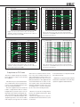
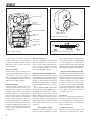
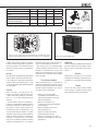
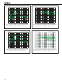
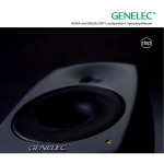
8040B
8050B
Operating Manual 2-6
Käyttöohje 7-11
Genelec 8040B and 8050B Active Monitoring Systems
Mounting considerations
System
Crossover
The GENELEC 8040B and 8050B are
two way active monitoring loudspeakers
designed to produce high SPL output, low
coloration and broad bandwidth in a small
enclosure size. They are suitable for a wide
variety of tasks, such as near field monitoring, mobile vans, broadcast and TV control
rooms, surround sound systems and home
studios. Designed as active loudspeakers, they contain drivers, power amplifiers,
The active crossover network consists of two
parallel bandpass filters. The crossover frequency is 3.0 kHz on the 8040B and 1.8 kHz
on the 8050B. The active crossover controls
(“treble tilt”, “desktop low frequency”, “bass tilt”
and “bass roll-off”) allow precise matching of
the loudspeakers to any room environment.
Always place the loudspeakers so that
their acoustic axes (see figure 2) are aimed
towards the listening position. Vertical placement is preferable, as it minimises acoustical
cancellation problems around the crossover
frequency.
Amplifiers
Check that the loudspeakers are placed symmetrically and at an equal distance from the
active crossover filters and protection circuitry. The Minimum Diffraction Enclosure™
(MDE™) and advanced Directivity Control
Waveguide™ (DCW™) technologies provide
excellent frequency balance even in difficult
acoustic environments.
Drivers
The bass driver dimensions are 165 mm (6
1/2”) and 205 mm (8”) for 8040B and 8050B
respectively. The long, flow optimized reflex
tube has a large cross sectional area and
terminates with a wide flare at the back of
the enclosure. The high frequency driver is a
19 mm (3/4”) metal dome on the 8040B and
a 25 mm (1”) metal dome on the 8050B. Both
drivers are magnetically shielded.
2
The amplifier unit is mounted in the rear of the
loudspeaker enclosure. The unit incorporates
special circuitry for driver thermal overload
protection. Variable input sensitivity allows
accurate level matching to console output
section.
Align the loudspeakers correctly
Maintain symmetry
listening position. If possible, place the system
so that the listening position is on the centerline of the room and the loudspeakers are
placed at an equal distance from the centerline.
Connections
Minimise reflections
Each loudspeaker is supplied with a mains
cable and an operating manual. Before connecting up, ensure that the mains switch
is off (see figure 1). Audio input is via a
10 kOhm balanced XLR connector, but unbalanced leads may be used as long as pin 3 is
grounded to pin 1 of the XLR (see figure 3).
Once the connections have been made, the
loudspeakers are ready to be switched on.
Acoustic reflections from objects close to the
loudspeakers like desks, cabinets, computer
monitors etc. can cause unwanted colouration
and blurring of the sound image. These can be
minimised by placing the loudspeaker clear of
reflective surfaces. For instance, putting the
loudspeakers on stands behind and above the
mixing console usually gives a better result
than placing them on the meter bridge.
REFLEX PORT
>0
,7 m
THREADS FOR
CEILING AND
WALL MOUNTS
WARNING
ACOUSTIC
AXIS
h
ELECTRIC SHOCK HAZARD!
IT IS FORBIDDEN TO UNDO ANY SCREWS ON THIS EQUIPMENT.
SERVICING AND ADJUSTMENT MUST ONLY BE CARRIED OUT
BY QUALIFIED SERVICE PERSONNEL.
NEVER OPERATE THIS EQUIPMENT WITHOUT A PROPER
EARTHED MAINS CONNECTION.
THIS EQUIPMENT IS CAPABLE OF PRODUCING SOUND PRESSURE
LEVELS IN EXCESS OF 85dB WHICH MAY CAUSE PERMANENT
HEARING DAMAGE.
DO NOT EXPOSE TO WATER OR MOISTURE.
TONE CONTROLS
INPUT SENSITIVITY
REQUIRED FOR
100dB SPL@1m.
+2
0
ON
OFF
+6
REFER TO THE OPERATING
MANUAL FOR SUGGESTED
TONE CONTROL SETTINGS.
-2
-4
+4
dBu
CAL POSITION
ALL TONE CONTROLS : OFF
INPUT SENSITIVITY : -6dBu
-6
8040B: h=240 mm
8050B: h=290 mm
SENSITIVITY
ADJUSTMENT
Figure 2. Location of the acoustic axis
MAINS INPUT
50 / 60 Hz 110 W 230 V~
1
2
3
+
-
GND
SERIAL NUMBER
MAGNETICALLY SHIELDED
www.genelec.com
MADE IN FINLAND
292-8005
8040B BI-AMPLIFIED
MONITORING SYSTEM
MAINS SWITCH AND
CONNECTOR PANEL
(HORIZONTAL)
Cable
Iso-Pod™ TABLE
STAND
Screen
RCA
(Source)
Figure 1. Amplifier panel layout of the 8040B
Minimum clearances
Sufficient cooling for the amplifier and functioning of the reflex port must be ensured if
the loudspeaker is installed in a restricted
space such as a cabinet, or integrated into
a wall structure. The surroundings of the
loudspeaker must always be open to the listening room with a minimum clearance of
5 centimeters (2”) behind, above and on both
sides of the loudspeaker. The space adjacent to the amplifier must either be ventilated
or sufficiently large to dissipate heat so that
the ambient temperature does not rise above
35 degrees Celsius (95°F).
Mounting options
The vibration insulating Isolation Positioner/
Decoupler™ (Iso-Pod™) table stand allows
tilting of the loudspeaker for correct alignment of the acoustic axis. The stand can be
attached to three mounting points allowing
vertical and symmetrical horizontal positioning (see figures 1 and 5).
Genelec 8040B and 8050B can be fitted
to Omnimount® Series 30 (8040B) and 60
(8050B) and König & Meyer loudspeaker
mounts on two sets of M6x10 mm threaded
holes on the back of the enclosure. On the
XLR
(Speaker)
Figure 3. RCA to XLR cable
base of the enclosure is an M10x10 mm
threaded hole which can be used for securing the loudspeaker to its base. Do not use
this thread for mounting the loudspeaker on
a microphone stand which has a 3/8” UNC
thread.
Setting the input sensitivity
The input sensitivity of the loudspeakers
can be matched to the output of the mixing
console, or other source, by adjusting the
input sensitivity control on the rear panel
(see figure 1). A screwdriver is needed for the
adjustment. The manufacturer’s default setting for this control is -6 dBu (fully clockwise)
which gives an SPL of 100 dB @1m with
-6 dBu input level.
Autostart function
The signal sensing Autostart function of the
loudspeakers powers them up when playback
begins. Automatic powering down of the loudspeakers happens one hour after the playback
has ended and the loudspeakers go to standby
mode. The power consumption in standby
mode is less than 0.5 watts. The loudspeakers will automatically and rapidly start once an
input signal is detected from the source.
Setting the tone controls
The frequency response of the system may
also have to be adjusted to match the acoustic environment. The adjustment is carried out
by setting the three tone control switch groups
“treble tilt”, “bass tilt” and “bass roll-off” on
the rear panel of the amplifier. There is also
a special “desktop low frequency” tone control
which gives an attenuation of 4 dB at 160 Hz
to compensate the effect of a mixing console,
desk or other reflective surface between the
listener and the loudspeaker. The factory settings for these controls are all “OFF” to give a
flat anechoic response.
Bass roll-off control
Bass roll-off (first switch group from the left)
affects the low frequency roll-off of the loudspeaker and attenuates its energy output near
the cut-off frequency. Attenuation levels of -2,
-4 or -6 dB can be selected.
Desktop low frequency control
The desktop low frequency control (fourth
switch of first switch group from the left)
attenuates the bass frequencies around
160 Hz by 4 dB (see figures 7 and 9). This
3
Speaker Mounting Position
Treble tilt
Bass tilt
Bass roll-off
Desktop LF
Flat anechoic response
None
None
None
None
Free standing in a damped
room
None
-2 dB
None
None
Free standing in a
reverberant room
None
-4 dB
None
None
Near field on a reflective
surface
None
-2 dB
None
-4 dB
In a corner
None
-4 dB
-4 dB
None
Table 1. Suggested tone control settings in some typical situations
Figure 4. K&M type wall mount
Figure 5. The Iso-Pod™ can also be attached to the side of the enclosure for
horizontal mounting.
feature is designed to compensate for the
boost often occurring at this frequency range
when the loudspeaker is placed upon a meter
bridge, table or similar reflective surface.
Bass tilt control
The bass tilt control switches (second switch
group from the left) offer three attenuation
levels for the bass response below 800 Hz,
usually necessary when the loudspeakers are placed near room boundaries. The
attenuation levels are -2 dB, -4 dB and
-6 dB.
switches to “OFF” position. Then set only one
switch per group to the “ON” position to select
the desired adjustment. If more than one
switch is set to “ON” (within one switch group)
the attenuation value is not accurate.
Measure or listen systematically through
the different combinations of settings to find
the best frequency balance.
Maintenance
No user serviceable parts are to be found
within the loudspeaker cabinet or the amplifier
unit. Any maintenance or repair of the loudspeaker should only be undertaken by qualified service personnel.
Treble tilt control
Treble tilt (third switch group from the left)
allows adjusting the treble response above
5 kHz by +2, -2, or -4 dB, which can be used
for correcting an excessively bright or dull
sounding system.
An acoustic measuring system such as
WinMLS is recommended for analyzing the
effects of the adjustments, however, careful listening with suitable test recordings can
also lead to good results if a test system is not
available. Table 1 shows some typical settings
in various situations. Figures 7 and 9 show
the effect of the controls on the anechoic
response.
Always start adjustment by setting all
4
Figure 6. Carrying bag for a pair of 8040B loudspeakers.
Safety considerations
Although the 8040B and 8050B have been
designed in accordance with international
safety standards, to ensure safe operation
and to maintain the loudspeaker under safe
operating conditions, the following warnings
and cautions must be observed:
• Servicing and adjustment must
only be performed by qualified service
personnel. The loudspeaker must not be
opened.
• Do not use this product with an
unearthed mains cable as this may lead
to personal injury.
• To prevent fire or electric shock, do not
expose the unit to water or moisture. Do
not place any objects filled with liquid, such
as vases on the loudspeaker or near it.
• Note that the amplifier is not
completely disconnected from the AC
mains service unless the mains power
cord is removed from the amplifier or the
mains outlet.
• Free flow of air behind the
loudspeaker
is necessary to maintain sufficient cooling.
Do not obstruct airflow around the
loudspeakers.
• Do not expose the loudspeaker to
water or moisture. Do not place any
objects filled with liquid, such as vases on
the loudspeaker or near it.
WARNING!
Genelec 8040B and 8050B loudspeakers are
capable of producing sound pressure levels in
excess of 85 dB, which may cause permanent
hearing damage.
Guarantee
Genelec 8040B and 8050B are supplied with
two year guarantee against manufacturing
faults or defects that might alter the performance of the loudspeakers. Refer to supplier
for full sales and guarantee terms.
Genelec Oy 8040
d
B
r
A
(dBr) vs freq (Hz) 6 Apr 04
Genelec Oy 8040 horizontal off axis response level (dBr) vs freq (Hz) 6 Apr 04
100
90
95
85
90 80
d
B
r
DESKTOP LF
A
85
80 90
90
0° 15° 30°
85
80
45°
75
BASS TILT
85
60°
100 70
80
95 65
BASS ROLL-OFF
TREBLE TILT
90 60
55
20
50
100
200
500
1k
2k
5k
50
20k
10k
20
50
100
200
500
1k
5k
2k
Hz
Figure 7. The curves above show the effect of the “bass tilt”,
“treble tilt”, “desktop low frequency” and “bass roll-off” controls on
the free field response of the 8040B.
Genelec Oy 8050
d
B
r
A
20k
10k
Hz
Figure 8. The upper curve group shows the horizontal directivity
characteristics of the 8040B measured at 1 m. The lower curve shows
the system's power response.
Genelec Oy 8050
(dBr) vs freq (Hz) 6 Apr 04
(dBr) vs freq (Hz) 6 Apr 04
100
95
90
85
d
B
r
DESKTOP LF
90 80
A
85
80 90
90
0° 15° 30°
85
80
75
BASS TILT
45°
60°
100 70
85
95 65
80
BASS ROLL-OFF
TREBLE TILT
90 60
55
20
50
100
200
500
1k
2k
5k
20k
10k
50
20
50
Figure 9. The curves above show the effect of the “bass tilt”,
“treble tilt”, “desktop low frequency” and “bass roll-off” controls on
the free field response of the 8050B
Compliance to FCC rules
This device complies with part 15 of the FCC
Rules. Operation is subject to the following
two conditions:
This device may not cause harmful interference, and this device must accept any interference received, including interference that
may cause undesired operation.
Note: This equipment has been tested and
found to comply with the limits for a Class
B digital device, pursuant to part 15 of the
FCC Rules. These limits are designed to provide reasonable protection against harmful
interference in a residential installation. This
equipment generates, uses and can radiate
radio frequency energy and, if not installed
100
200
500
1k
2k
5k
20k
10k
Hz
Hz
Figure 10. The upper curve group shows the horizontal directivity
characteristics of the 8050B measured at 1 m. The lower curve shows
the system's power response.
and used in accordance with the instructions, may cause harmful interference to
radio communications. However, there is no
guarantee that interference will not occur in a
particular installation. If this equipment does
cause harmful interference to radio or television reception, which can be determined by
turning the equipment off and on, the user is
encouraged to try to correct the interference
by one or more of the following measures:
3. Consult the dealer or an experienced radio/
TV technician for help
Modifications not expressly approved by the
manufacturer could void the user’s authority to
operate the equipment under FCC rules.
1. Reorient or relocate the receiving antenna.
Increase the separation between the equipment and receiver.
2. Connect the equipment into an outlet on a
circuit different from that to which the receiver
is connected.
5
SYSTEM SPECIFICATIONS
CROSSOVER SECTION
8040B
8050B
Lower cut-off frequency, -3 dB
Upper cut-off frequency, -3 dB
≤ 45 Hz
≥ 21 kHz
≤ 35 Hz
≥ 21 kHz
Free field frequency response of
system (± 2.0 dB)
48 Hz - 20 kHz
38 Hz - 20 kHz
Maximum short term sine wave
acoustic output on axis in half
space, averaged from 100 Hz to
3 kHz
@1m
@ 0.5 m
≥ 105 dB SPL
≥ 111 dB SPL
≥ 110 dB SPL
≥ 116 dB SPL
Maximum long term RMS acoustic output in same conditions
with IEC weighted noise (limited
by driver unit protection circuit)
@1m
≥ 99 dB SPL
≥ 101 dB SPL
Maximum peak acoustic output
per pair above console top, @ 1
m distance with music material
≥ 115 dB SPL
≥ 120 dB SPL
Self generated noise level in free
field @ 1m on axis (A-weighted)
≤ 10 dB
≤ 10 dB
<2%
< 0.5 %
<2%
< 0.5 %
Drivers:
Bass
Treble
Both drivers are
magnetically shielded
165 mm (6 1/2")
19 mm (3/4")
metal dome
205 mm (8")
25 mm (1")
metal dome
Weight:
8.6 kg (18.9 lbs)
12.7 kg (28 lbs)
350 mm (13
13/16“)
365 mm (14 3/8“)
237 mm (9 3/8“)
223 mm (8 13/16“)
433 mm (17 1/16")
452 mm (17
13/16")
286 mm (11 1/4")
278 mm (10
15/16")
Harmonic distortion at 90 dB SPL
@ 1m on axis
Freq. 50 to 100 Hz
> 100 Hz
Dimensions:
Height (without table support
Height (including table support)
Width
Depth
6
8040B
8050B
Input connector XLR female
Pin 1 gnd, pin 2 +, pin 3 -
Input impedance
10 kOhm balanced
Input level for maximum short term
output of 100 dB SPL @ 1m:
Adjustable from +6 to -6 dBu
Crossover frequency, Bass/Treble
3.0 kHz
1.8 kHz
Treble tilt control operating range in
2 dB steps
From +2 to -4 dB &
MUTE @ 15 kHz
From +2 to -4 dB &
MUTE @ 15 kHz
Desktop low frequency control
operating range
-4 dB @ 160 Hz
-4 dB @ 160 Hz
Bass roll-off control operating
range in 2 dB steps
From 0 to -6 dB
@ 45 Hz
From 0 to -6 dB
@ 35 Hz
Bass tilt control operating range in
2 dB steps
From 0 to -6 dB @
100 Hz & MUTE
From 0 to -6 dB @
100 Hz & MUTE
The 'CAL' position is with all tone controls set to 'off' and the input sensitivity
control to maximum (fully clockwise)
AMPLIFIER SECTION
8040B
Bass amplifier short
term output power
Treble amplifier short
term output power
8050B
90 W
90 W)
150 W
120 W
Amplifier system distortion
at nominal output
THD
SMPTE-IM
CCIF-IM
DIM 100
≤ 0.05 %
≤ 0.05 %
≤ 0.05 %
≤ 0.05 %
≤ 0.05 %
≤ 0.05 %
≤ 0.05 %
≤ 0.05 %
Signal to Noise ratio, referred to
full output
Bass
Treble
≥ 100 dB
≥ 100 dB
≥ 100 dB
≥ 100 dB
Long term output power is limited
by driver unit protection circuitry
Mains voltage
100, 120, 220 or 230 V
according to region
Voltage operating range
±10 %
±10 %
Power consumption
Idle
Standby
Full output
10 W
< 0.5 W
110 W
10 W
<0.5 W
170 W
Genelec 8040B- ja 8050B-aktiivikaiuttimet
Yleistä
Aktiivinen jakosuodin
GENELEC 8040B ja 8050B ovat erittäin suorituskykyisiä, kompakteja aktiivikaiuttimia.
Ne soveltuvat lähikenttämonitoreiksi äänitysstudioihin, ulkolähetysautoihin, radio- ja
TV-lähetysten äänen tarkkailuun, julkisiin
tiloihin, kotistudioihin ja kotiteattereihin.
Molemmat mallit sisältävät päätevahvistimet,
säädettävän aktiivisen jakosuotimen ja kaiutinelementtien ylikuormitussuojauspiirit. Uusi
Minimum Diffraction Enclosure™ (MDE™)-
Aktiivinen jakosuodin koostuu kahdesta rinnakkaisesta kaistanpäästösuotimesta. Jakotaajuus on mallissa 8040B 3,0 kHz ja mallissa 8050B 1,8 kHz. Jakosuotimen säädöt
(“treble tilt”, “desktop low frequency”, “bass
tilt” ja “bass roll-off”) mahdollistavat kaiuttimen
toistovasteen sovittamisen erilaisiin akustisiin
ympäristöihin.
kotelorakenne ja edelleen kehitetty Directivity Control Waveguide™ (DCW™)-suuntain
takaavat tasapainoisen toiston vaikeissakin
akustisissa ympäristöissä.
Genelec 8040B ja 8050B -aktiivikaiuttimet
sisältävät kaiutinelementteihin suoraan kytketyt
päätevahvistimet. 8040B:n molemmat vahvistimet ovat teholtaan 90 wattia, 8050B:ssa on
diskanttielementille 120 watin ja bassoelementille 150 watin vahvistin. Kaiutinkotelon sisään
rakennetut vahvistimet on varustettu automaattisilla suojapiireillä kaiutinelementtien ylikuumenemisen varalta. Vahvistimien säädettävä
sisääntuloherkkyys mahdollistaa kaiuttimien
sovittamisen erilaisiin äänilähteisiin.
Kaiuttimissa on signaalin tunnistava automaattinen virrankytkentä, joka kytkee ne
toimintaan heti kun kaiuttimeen tulee äänisignaali. Vastaavasti kaiuttimet menevät
automaattisesti valmiustilaan, kun signaalin
päättymisestä on kulunut tunti. Valmiustilassa
kaiuttimien tehonkulutus on alle 0,5 W.
Liitännät
Kaiuttimien sijoitus
Kaiuttimien mukana toimitetaan suojamaadoitetut verkkovirtajohdot. Älä kytke kaiutinta
suojamaadoittamattomaan pistorasiaan.
Kohdista kuuntelupisteeseen
Suuntaa kaiuttimet kuuntelualueen keskipisteeseen pään korkeudelle. Suuntaus
Kaiutinelementit
Bassoelementin läpimitta on mallissa 8040B
165 mm (6 1/2”) ja 205 mm (8”) mallissa
8050B. Pitkän ja poikkileikkaukseltaan suuren
refleksiputken aukko on muotoiltu laajenevaksi ilmavirtauksesta johtuvien sivuäänien
minimoimiseksi. Diskanttielementti on metallikalotti, läpimitaltaan 19 mm (3/4”) 8040B:ssa
ja 25 mm (1”) 8050B:ssa. Sekä basso- että
diskanttielementit on magneettisuojattu.
Vahvistimet
Ennen kuin teet mitään kytkentöjä, varmista, että kaikista laitteista on kytketty virta
pois. Audiosignaalia varten kaiuttimissa on
balansoitu 10 kOhm:in XLR-liitin. Ellei äänilähteessä ole balansoitua antoliitäntää, voidaan käyttää kuvan 3 mukaisesti kytkettyä
signaalijohtoa. Genelec 8040B- ja 8050Baktiivikaiuttimet saa kytkeä ainoastaan linjatasoista signaalia antavaan äänilähteeseen, ei
milloinkaan päätevahvistimen tai integroidun
vahvistimen kaiutinliittimiin.
Automaattinen virrankytkentä
(Autostart)
7
REFLEKSIAUKKO
>0
,7 m
KIERTEET
LAIPIO- JA
SEINÄTELINEILLE
WARNING
h
AKUSTINEN
AKSELI
ELECTRIC SHOCK HAZARD!
IT IS FORBIDDEN TO UNDO ANY SCREWS ON THIS EQUIPMENT.
SERVICING AND ADJUSTMENT MUST ONLY BE CARRIED OUT
BY QUALIFIED SERVICE PERSONNEL.
NEVER OPERATE THIS EQUIPMENT WITHOUT A PROPER
EARTHED MAINS CONNECTION.
THIS EQUIPMENT IS CAPABLE OF PRODUCING SOUND PRESSURE
LEVELS IN EXCESS OF 85dB WHICH MAY CAUSE PERMANENT
HEARING DAMAGE.
DO NOT EXPOSE TO WATER OR MOISTURE.
TAAJUUSVASTESÄÄTIMET
INPUT SENSITIVITY
REQUIRED FOR
100dB SPL@1m.
+2
0
+4
ON
OFF
+6
REFER TO THE OPERATING
MANUAL FOR SUGGESTED
TONE CONTROL SETTINGS.
-2
-4
dBu
CAL POSITION
ALL TONE CONTROLS : OFF
INPUT SENSITIVITY : -6dBu
-6
MAINS INPUT
50 / 60 Hz 110 W 230 V~
HERKYYDEN
SÄÄDIN
8040B: h=240 mm
8050B: h=290 mm
Kuva 2. Akustisen akselin sijainti
1
2
3
+
SERIAL NUMBER
MAGNETICALLY SHIELDED
www.genelec.com
MADE IN FINLAND
-
GND
292-8005
8040B BI-AMPLIFIED
MONITORING SYSTEM
VIRTAKYTKIN JA
LIITINPANEELI
Iso-Pod™ TABLE
STAND
Kuva 1. 8040B:n takapaneeli
on tehty oikein, kun kaikkien kaiuttimien
akustiset akselit (kuva 2) leikkaavat kuuntelupisteessä. Kaiuttimet kannattaa sijoittaa
pystyasentoon, sillä se minimoi vaihevirheet
jakotaajuudella.
Sijoita symmetrisesti
Sijoita kaiuttimet samalle etäisyydelle kuuntelupisteestä ja mahdollisimman symmetrisesti
sekä toistensa, että huoneen rajapintojen
suhteen. Tämä toteutuu, kun kuuntelupiste on
huoneen keskilinjalla ja kaiuttimet sijoitetaan
symmetrisesti keskilinjan suhteen.
Minimoi heijastukset
Kaiuttimen lähellä sijaitsevista esineistä ja
pinnoista tulevat akustiset heijastukset voivat
aiheuttaa toiston värittymistä ja sumentaa
äänikuvaa. Tämä kannattaa ottaa huomioon
kaiuttimia sijoitettaessa ja mahdollisuuksien
mukaan siirtää heijastuksia aiheuttavat tietokoneen näytöt, kaapit tms. pois kaiuttimien
läheltä ja sijoittaa kaiuttimet niin, että ne ovat
kauempana jäljelle jäävistä heijastuksia aiheuttavista pinnoista. Tarkkailukaiuttimia ei esimerkiksi kannata sijoittaa äänipöydän päälle, vaan
riittävän korkeille lattiajalustoille äänipöydän
taakse, josta ne voidaan suunnata alas äänitarkkailijaa kohti.
8
Kuva 3. RCA/XLR-signaalikaapelin kytkentä
Vähimmäisetäisyydet
Vahvistimien jäähdytyksen ja refleksiputken
toiminnan takaamiseksi pitää kaiuttimien
taakse, sivuille ja päälle jäädä kuunteluhuoneeseen avautuva, vähintään viiden senttimetrin vapaatila. Kaiutinta ei saa käyttää
tilassa, jonka lämpötila on yli 35° C.
Säätö tehdään kaiuttimen takapaneelissa
olevaa ruuvia (ks. kuva 1) kiertämällä. Säätö
on asetettu tehtaalla arvoon -6 dBu (myötäpäivään rajoittajaan asti), mikä tuottaa 100
dB:n äänenpaineen (SPL) yhden metrin mittausetäisyydellä -6 dBu:n syöttöjännitteellä.
Pöytäjalusta ja kiinnitysmahdollisuudet
Kaiuttimien mukana toimitettava Isolation
Positioner/Decoupler™ (Iso-Pod™) -jalusta
mahdollistaa kaiuttimen kallistamisen ylä- tai
Kaiuttimien taajuusvastetta voidaan muokata
kuuntelutilan akustisista ominaisuuksista ja
kaiuttimien sijoituksesta johtuvien toistovirheiden kompensoimiseksi. Säätö tehdään
alaviistoon. Jalusta voidaan kiinnittää myös
kaiutinkotelon pitkille sivuille, jos kaiuttimet
halutaan sijoittaa vaaka-asentoon. (kuvat 1
ja 4).
Genelec 8040B ja 8050B voidaan kiinnittää Omnimount® Series 30 (8040B) ja Series
60 (8050B) sekä König & Meyer -kaiutintelineisiin kaiutinkotelon takaseinässä olevien
M6x10 -mutterikierteiden avulla. Kotelon
pohjassa on M10x10 -mutterikierre, jolla kaiutin voidaan kiinnittää tukevasti alustaansa.
Älä käytä tätä kierrettä kaiuttimen kiinnittämiseen mikrofonitelineeseen, jossa on 3/8”
UNC-kierre.
kaiuttimen takapaneelissa olevien “treble
tilt”, “bass tilt”, “bass roll-off” ja “desktop low
frequency” -kytkimien avulla. Kaikki säädöt
asetetaan tehtaalla asentoon “OFF”, mikä
antaa tasaisen taajuusvasteen kaiuttomassa
tilassa. Säätöjen vaikutus toistovasteeseen
on esitetty kuvissa 7 ja 9.
Herkkyyden säätö
Desktop low frequency
Desktop low frequency-säätö (neljäs kytkin
ensimmäisessä säädinryhmässä) aktivoi
Kaiuttimien ottoliitännän herkkyys on säädettävissä erilaisille äänilähteille sopivaksi.
Taajuusvastesäätöjen käyttö
Bass roll-off
Bass roll-off (ensimmäinen kytkinryhmä vasemmalta lukien) vaikuttaa kaiuttimen bassotoistoon alarajataajuudella ja sen lähellä. Kolmella
kytkimellä voidaan valita -2, -4 tai -6 dB:n vaimennus (ks. kuvat 7 ja 9).
Kaiuttimien sijoitus
Treble tilt
Bass tilt
Bass roll-off
Desktop LF
Kaiuttomassa tilassa
OFF
OFF
OFF
OFF
Vapaasti seisovana vaimennetussa
tilassa
OFF
-2 dB
OFF
OFF
Vapaasti seisovana kaikuvassa tilassa
OFF
-4 dB
OFF
OFF
Lähikentässä, heijastavan tason
päällä (esim. äänipöydällä)
OFF
-2 dB
OFF
-4 dB
Nurkassa
OFF
-4 dB
-4 dB
OFF
Taulukko 1. Taajuusvastesäätimien käyttö muutamissa tyypillisissä tilanteissa
Kuva 4. Iso-Pod™ -pöytäjalusta voidaan kiinnittää myös kaiutinkotelon sivulle.
Kaiuttimet tulisi kuitenkin sijoittaa pystyasentoon aina kun se on mahdollista
4 dB:n vaimennuksen 160 Hz:n kohdalle
kompensoimaan äänipöydän, pöytätason
tai muun kaiuttimen ja kuuntelijan välissä
sijaitsevan vaakasuoran tason aiheuttaman
korostuman.
Bass tilt
Bass tilt-säädön (keskimmäinen kytkinryhmä)
avulla voidaan vaimentaa kaiuttimen bassotoistoa 100 hertsin alapuolella. Kolmella kytkimellä voidaan valita vaimennustasot -2 dB,
-4 dB ja -6 dB. Neljäs kytkin (MUTE) mykistää
bassoelementin.
Treble tilt
Treble tilt-säätö (oikeanpuoleinen kytkinryhmä) vaikuttaa diskanttitaajuuksiin
5 kHz:n yläpuolella. Valittavana ovat säätötasot +2, -2, tai -4 dB ja diskanttielementin
mykistys.
Suosittelemme akustisen mittausjärjestelmän (esim. MLSSA tai WinMLS) käyttöä
kaiuttimien säätämisessä. Ellei tällaista ole
käytettävissä, säätö voidaan tehdä myös
korvakuulolta sopivia testiäänitteitä ja -signaaleja hyväksikäyttäen. Taulukko 1 sisältää
muutamia suuntaa-antavia säätöesimerkkejä.
Säätöjen vaikutus kaiuttimien vapaakenttävasteisiin on esitetty kuvissa 7 ja 9. Kaiuttimien sijoitus ja akustinen ympäristö vaikuttaa
ratkaisevasti säätötarpeeseen, joten säätöön
Kuva 5. Seinäteline 8000-402
Kuva 6. Kantolaukku 8040B-parille
kannattaa ryhtyä vasta kun kuuntelutilan järjestys on saatu lopulliseen muotoonsa.
Bass tilt-, bass roll off- ja treble tilt-säätöjä
voidaan yhdistellä vapaasti parhaan sointitasapainon saavuttamiseksi. Huomaa, että
säädöt eivät ole kumuloituvia, joten kussakin
ryhmässä saa olla kerrallaan vain yksi kytkin
asennossa “ON”.
Turvallisuusohjeita
Genelec-aktiivikaiuttimet on suunniteltu ja
valmistettu täyttämään kansainväliset turvallisuusnormit. Virheellisestä käytöstä saattaa
kuitenkin seurata vaaratilanne, joten seuraavia ohjeita on aina noudatettava:
• Laitetta ei saa asettaa alttiiksi
•
•
•
•
VAROITUS!
Genelec 8040B ja 8050B-aktiivikaiuttimet
pystyvät tuottamaan yli 85 desibelin äänenpaineen, mikä voi aiheuttaa pysyvän kuulovaurion.
Huolto
Kaikki huolto- ja korjaustoimet on annettava
valmistajan tai valmistajan valtuuttaman huoltohenkilöstön suoritettaviksi. Älä avaa laitetta
itse.
Takuu
Genelec Oy antaa näille tuotteille kahden
vuoden takuun ostopäivästä lukien. Takuu
kattaa valmistusvirheet ja materiaaliviat.
kosteudelle tai roiskevedelle. Se on
tarkoitettu käytettäväksi ainoastaan
kuivassa huonetilassa.
Huolto- ja korjaustoimia saa
suorittaa vain valmistajan valtuuttama
huoltohenkilöstö.
Älä avaa kaiutinkoteloa tai irrota
laitteesta mitään osia.
Laitteen saa kytkeä ainoastaan
maadoitettuun pistorasiaan.
Huomaa, että vahvistin ei ole täysin
jännitteetön ellei virtajohtoa ole irrotettu
pistokkeesta.
9
Genelec Oy 8040
d
B
r
A
(dBr) vs freq (Hz) 6 Apr 04
Genelec Oy 8040 horizontal off axis response level (dBr) vs freq (Hz) 6 Apr 04
100
90
95
85
90 80
d
B
r
DESKTOP LF
A
85
80 90
90
0° 15° 30°
85
80
45°
75
BASS TILT
85
60°
100 70
80
95 65
BASS ROLL-OFF
TREBLE TILT
90 60
55
20
50
100
200
500
1k
2k
5k
50
20k
10k
20
50
100
200
500
1k
5k
2k
Hz
Kuva 7. “Bass tilt”-, “treble tilt”-, “desktop low frequency”- ja “bass
roll-off”-säätöjen vaikutus 8040B:n vapaakenttävasteeseen.
Genelec Oy 8050
d
B
r
A
20k
10k
Hz
Kuva 8. Ylempi käyrästö kuvaa 8040B:n suuntaavuuskäyttäytymistä 1
metrin mittausetäisyydellä. Alempi käyrä on 8040B:n tehovaste.
Genelec Oy 8050
(dBr) vs freq (Hz) 6 Apr 04
(dBr) vs freq (Hz) 6 Apr 04
100
95
90
85
d
B
r
DESKTOP LF
90 80
A
85
80 90
90
0° 15° 30°
85
80
75
BASS TILT
45°
60°
100 70
85
95 65
80
BASS ROLL-OFF
TREBLE TILT
90 60
55
20
50
100
200
500
1k
2k
5k
20k
10k
Hz
Kuva 9. “Bass tilt”-, “treble tilt”-, “desktop low frequency”- ja “bass
roll-off”-säätöjen vaikutus 8050B:n vapaakenttävasteeseen.
10
50
20
50
100
200
500
1k
2k
5k
20k
10k
Hz
Kuva 10. Ylempi käyrästö kuvaa 8050B:n suuntaavuuskäyttäytymistä 1
metrin mittausetäisyydellä. Alempi käyrä on 8050B:n tehovaste.
TEKNISET TIEDOT
JAKOSUODIN
8040B
8050B
Alarajataajuus, -3 dB
Ylärajataajuus, -3 dB
≤ 45 Hz
≥ 21 kHz
≤ 35 Hz
≥ 21 kHz
Taajuusvaste vapaakentässä
(± 2.0 dB)
48 Hz - 20 kHz
38 Hz - 20 kHz
Hetkellinen maksimiäänenpaine
mitattuna sinisignaalilla puoliavaruudessa. Keskiarvo taajuusalueella 100 Hz - 3 kHz
@1m
@ 0.5 m
8040B
8050B
Ottoliittäntä XLR naaras
Napa 1 maa, napa 2 +, napa 3 -
Ottoliitännän impedanssi
10 kOhm symmetrinen
Herkkyyden säätöalue
+6 ... -6 dBu 100 dB:n äänenpainetasolla 1
metrin mittausetäisyydellä
Jakotaajuus
3,0 kHz
1,8 kHz
Treble tilt-säätö 2 dB:n portain
+2 ... -4 dB &
MUTE @ 15 kHz
+2 ... -4 dB & MUTE
@ 15 kHz
≥ 105 dB SPL
≥ 111 dB SPL
≥ 110 dB SPL
≥ 116 dB SPL
Desktop low frequency-säätö
-4 dB @ 160 Hz
-4 dB @ 160 Hz
Suurin jatkuva (RMS) äänenpaine
IEC-painotetulla kohinalla mitattuna (elementtien suojapiirien
rajoittama) @ 1 m
≥ 99 dB SPL
≥ 101 dB SPL
Bass roll-off-säätö 2 dB:n portain
0 ... -6 dB
@ 45 Hz
0 ... -6 dB
@ 35 Hz
Bass tilt-säätö 2 dB:n portain
0 ... -6 dB @ 100
Hz & MUTE
0 ... -6 dB @ 100 Hz
& MUTE
Kaiutinparin tuottama äänenpaineen huippuarvo (peak)
musiikkimateriaalilla 1 metrin
mittausetäisyydellä
≥ 115 dB SPL
≥ 120 dB SPL
Akustinen pohjakohinataso @ 1
m (A-painotus)
≤ 10 dB
≤ 10 dB
<2%
< 0,5 %
<2%
< 0,5 %
Kaiutinelementit:
Basso
Diskantti
Molemmat elementit ovat
magneettisuojattuja
165 mm (6 1/2")
19 mm (3/4")
metallikalotti
205 mm (8")
25 mm (1")
metallikalotti
Paino:
8,6 kg
12,7 kg
Mitat:
Korkeus ilman pöytäjalustaa
Korkeus pöytäjalustan kanssa
Leveys
Syvyys
350 mm (13 13/16“)
365 mm (14 3/8“)
237 mm (9 3/8“)
223 mm (8 13/16“)
433 mm (17 1/16")
452 mm (17 13/16")
286 mm (11 1/4")
278 mm (10 15/16")
Harmoninen särö 90 dB SPL
@1m
50 - 100 Hz
> 100 Hz
Kaiuttimien kalibrointiasetus: Kaikki
taajuusvastesäätimet asennossa "OFF" ja
herkkyyden säädin maksimiasennossa
VAHVISTIMET
8040B
Bassovahvistimen lyhytkestoinen
maksimiteho
Diskanttivahvistimen
lyhytkestoinen maksimiteho
8050B
90 W
150 W
90 W
120 W
Vahvistimien särö nimellisteholla
THD
SMPTE-IM
CCIF-IM
DIM 100
≤ 0.05 %
≤ 0.05 %
≤ 0.05 %
≤ 0.05 %
≤ 0.05 %
≤ 0.05 %
≤ 0.05 %
≤ 0.05 %
Kohinaetäisyys täydellä teholla
Basso
Diskantti
≥ 100 dB
≥ 100 dB
≥ 100 dB
≥ 100 dB
Käyttöjännite
230 V
Sallittu jännitteen vaihtelu
±10 %
±10 %
Tehonkulutus
Ilman kuormaa
Valmiustilassa
Maksimikuormalla
10 W
<0,5 W
110 W
10 W
<0,5 W
170 W
Jatkuvaa tehoa rajoittaa kaiutinelementtien suojauselektroniikka
11
www.genelec.com
Genelec Document D003R001b Copyright Genelec Oy 2.2013. All data subject to change without prior notice.
International enquiries:
In the U.S. please contact:
In Sweden please contact:
In China please contact:
Genelec, Olvitie 5
Genelec, Inc., 7 Tech Circle
Genelec Sverige
Beijing Genelec Audio Co.Ltd
FIN-74100, Iisalmi, Finland
Natick, MA 01760, USA
Ellipsvägen 10B
Jianwai SOHO, Tower 12,
Phone +358 17 83881
Phone +1 508 652 0900
P.O. Box 5521, S-141 05 Huddinge
Room 2605
Fax +358 17 812 267
Fax +1 508 652 0909
Phone +46 8 449 5220
D-1504, Chaoyang District
Email [email protected]
Email [email protected]
Fax +46 8 708 7071
Beijing 100022, China
Email [email protected]
Phone +86 10 8580 2180
Fax +86 10 8580 2181
Email [email protected]