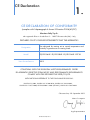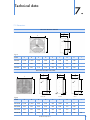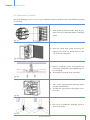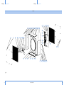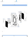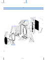
1
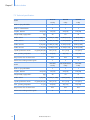
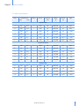
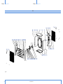
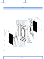
Manual for use and maintenance
+ CE Declaration of conformity
ED/EDS/EDT HE
Air extraction/circulation fan
Models: ED/EDS36HE - ED/EDS30HE
ED/EDS24HE - EDT30HE
Ag/MIT/UmGB-2145-10/13 rev 1.0
EDHE
EDSHE
EDTHE
ED/EDS/EDT HE
Manual for use and maintenance
Original instructions
This manual for use and maintenance is an integral part of the apparatus together with the attached technical
documentation and has been produced with reference to Directive 2006/42/EC, paragraph A, Annex II, and to
ErP Directive 2009/125/CE Commission Regulation 327/2011.
This document is destined for the user of the apparatus: it may not be reproduced in whole or in part, committed
to computer memory as a file or delivered to third parties without the prior authorisation of the assembler of the
system.
Munters Italy S.p.A. reserves the right to effect modifications to the apparatus in accordance with technical and
legal developments.
2
© Munters AB, 2013
Index
chapter
1.
2.
3.
4.
5.
6.
page
CE DECLARATION
5
1.1
1.2
1.3
1.4
1.5
6
6
6
6
7
Disclaimer
Introduction
Notes
Data for Fan Ecodesign Directive
Attached technical documentation
SAFETY ASPECTS
8
2.1 Personnel requirements
2.2 General safety instructions
2.3 Safety devices
2.4 Residual risks
8
9
9
11
BEFORE USING
13
3.1 Delivery check
3.2 Packaging and transport of assembled fans
3.3 Structure
13
13
13
OPERATING CONDITIONS
14
4.1 Intended conditions of use
4.2 Non-permitted conditions of use
14
14
INSTALLATION
17
5.1 Choice of site and checking installation requirements
5.2 Installing Series EM fans
5.3 Installing Series EMS fans
5.4 Connection to the electrical system
5.5 Tests and checks before startup
17
18
19
19
22
COMMISSIONING
23
6.1 Control devices
6.2 Instructions for machine use
23
23
© Munters AB, 2013
3
Index
7.
4
TECHNICAL DATA
25
7.1 Dimensions
7.2 Technical specifications
7.3 Motor specifications
25
26
27
8.
MAINTENANCE
8.1 Introduction
8.2 Cleaning
8.3 Replacement of propeller
8.4 Replacement of shutter bearing assembly
8.5 Fan bearing lubrication
8.6 Replacement of shutter opening device (centrifugal system)
28
9.
SPARE PART LIST
32
10.
WARRANTY
56
© Munters AB, 2013
28
28
29
30
31
31
CE Declaration
1.
CE DECLARATION OF CONFORMITY
(complies with Subparagraph A Annex II Directive 2006/42/EC)
Munters Italy S.p.A.
with registered offices in Strada Piani 2 – 18027 Chiusavecchia (IM) – Italy
DECLARES ON ITS OWN RESPONSIBILITY THAT THE APPARATUS
Designation
Model
Year of manufacture
Fan designed for moving air to control temperature and
humidity in greenhouses or rearing sheds.
ED/EDS36HE - ED/EDS30HE - ED/EDS24HE - EDT30
2013
conforms with the essentiAl safety requirements stated
by Apparatus Directive 2006/42/EC and performance requirements
comply with the eRp directive 2009/125/ce.
With particular reference to the following provisions:
UNI EN 953:2009, UNI EN ISO 12100:2010, UNI EN ISO 12499:2009,
UNI EN ISO 13857:2008, CEI EN 60204-1:2006 (CEI 44-5), uni EN iso 5801:2009
Chiusavecchia, 25th September 2013
Marco Scomparin
Legal representative
© Munters AB, 2013
5
Chapter1
CE Declaration
1.1 Disclaimer
Munters reserves the right to make alternations to specifications, quantities, dimensions etc. for production or other
reasons, subsequent to publication. The information contained herein has been prepared by qualified experts within
Munters. While we believe the information is accurate and complete, we make no warranty or representation for
any particular purposes. The information is offered in good faith and with the understanding that any use of the
units or accessories in breach of the directions and warnings in this document is at the sole discretion and risk of
the user.
1.2 Introduction
Congratulations on your excellent choice of purchasing an Euroemme® fan!
In order to realize the full benefit from this product it is important that it is installed, commissioned and operated
correctly. Before installation or using the fan, this manual should be studied carefully. It is also recommended that
it is kept safely for future reference. The manual is intended as a reference for installation, commissioning and dayto-day operation of the Euroemme fans.
1.3 Notes
Date of release: 2013.
Munters cannot guarantee to inform users about the changes or to distribute new manuals to them.
All rights reserved. No part of this manual may be reproduced in any manner whatsoever without the expressed
written permission of Munters. The contents of this manual are subject to change without notice.
1.4 Data for Fan Eco Design Directive
Product information requirements* →
Specific ratio
8
RPM at optimum energy efficiency
7
Pressure at optimum energy
efficiency [Pa]
6c
Flow rate at optimum energy
efficiency [m3/h]
6b
Motor power input at optimum
energy efficiency [W]
6a
VSD must be installed with the fan
5
Target efficiency grade 2013
(2015)
optional
Efficiency grade
4
Efficiency category
3
Measurement category
2
ED36HE 0.75hp 3ph 50Hz OS
34,6
A
static
41,4
36 (40)
no
834
13.140
78,9
898
1
ED36HE 0.75hp 3ph 50Hz MS
32,7
A
static
39,3
36 (--)
no
900
12.783
82,8
882
1
ED36HE 0.75hp 1ph 50Hz MS
31,0
A
static
37,7
36 (--)
no
888
10.970
90,4
907
1
ED30HE 0.50hp 3ph 50Hz OS
34
A
static
41,8
36 (40)
no
588
9.149
78,8
846
1
ED30HE 0.50hp 3ph 50Hz MS
32,6
A
static
40,3
36 (40)
no
604
8.989
78,7
887
1
ED30HE 0.50hp 1ph 50Hz MS
30,2
A
static
38,2
36 (--)
no
557
7.713
78,7
904
1
ED24HE 0.50hp 3ph 50Hz OS
32,4
A
static
40,2
36 (40)
no
590
6.300
109,5 1.289
Fan description*
6
1
Overall efficiency η%
(according to ANNEX I - 3.2 of regulation)
© Munters AB, 2013
1
Chapter1
CE Declaration
ED24HE 0.50hp 3ph 50Hz MS
33
A
static
41
36 (40)
no
539
5.845
109,5 1.320
1
ED24HE 0.50hp 1ph 50Hz MS
29,3
A
static
37,3
36 (--)
no
545
5.294
108,6 1.320
1
1.5 Attached technical documentation
The listed documentation is to be considered an integral part of this manual:
• technical sheet/electric motor instruction booklet.
© Munters AB, 2013
7
Safety aspects
Warning
2.
Failure to respect safety or behavioural rules can produce hazardous situations
for users as well as damage to the machine and the place where it is installed.
The fan must only be used if it is in perfect operating condition, by personnel who
are perfectly aware of the safety measures and possible hazards, and in strict
compliance with the instructions given in this manual.
2.1 Personnel requirements
Equipment may only be used by personnel who know and apply the specific requirements given in the user and
maintenance manual and the more general instructions contained in various regulations for accident prevention
and applicable legislation regarding safety in the workplace, as well as other European Community directives
incorporated by the member states into their national legislation.
Knowledge and understanding of the manual and of the attached documents constitute an indispensable tool for
reducing hazards and promoting the safety and health of workers.
Personnel training
All operators engaged in the use of the fan must have received adequate information from the employer relating
to:
• risks to health and safety at work connected with the use of the machine;
• first aid procedures, fire precautions and evacuation of workplaces;
• devices provided for the safety of operators, and residual risks generated by the machine.
In particular, the employer has the following duties:
• when assigning tasks to operators, to take into account their capabilities in the interests of safeguarding
their health and safety;
• to provide adequate means of protection;
• to require compliance by individual operators with the company rules and provisions regarding safety and
the use of the collective and individual protective measures at their disposal;
• to ensure that normal and special maintenance operations, or in any event operations necessary for machine
safety, are regularly carried out.
All operators must take care of their own safety and health as well as that of other people in the workplace who
may be affected by their actions or omissions, in accordance with their personal skills, and the instructions and
means provided to them by the employer.
Warning
8
Unauthorized tampering/replacement of one or more parts of the machine, or
the use of accessories, tools or materials other than those recommended by the
manufacturer, are prohibited and release the manufacturer from all liability.
© Munters AB, 2013
Chapter2
Safety aspects
Warning
Operators must be trained to deal with the occurrence of possible faults,
malfunctions or dangerous conditions to themselves or others, and in such an
event must:
• stop the fan immediately by operating the emergency stop device (mushroomshaped pushbutton/main switch mounted on the electrical panel);
• not carry out operations which are beyond their duties and/or technical
knowledge.
2.2 General safety instructions
Warning
• Safety devices must not be removed or rendered ineffective;
• the fan must not be started with guards removed;
• any adjustment or maintenance operation must be performed with the
electrical isolating device activated and locked in position with a padlock;
• any operation is prohibited which may cause arcing or sparks or other
situations which could start a fire;
• in the event of alarm signals resulting in the intervention of safety devices, the
operator must ask for immediate action by qualified technicians responsible
for maintenance;
• user must ensure that the environmental and electricity supply conditions
in which the fan operates are always within the limits specified in this user
manual;
• do not for any reason modify parts of the fan in order to fit additional devices.
2.3 Safety devices
In the process of designing and building the fan, the manufacturer adopted the necessary technical solutions to
ensure compliance with fundamental safety requirements: the object of the risk reduction process was to ensure
that the operator can use the fan in safety. The machine is provided with protection devices of fixed type and is
fitted with an actuator for the emergency stop function.
Fixed guards
The fixed guards are solidly fixed to the structure of the machine and cannot easily be eluded: the guards are fixed
with systems which require the use of tools for dismantling.
Warning
Do not start the fan with fixed guards removed: the guards can only be removed
with special tools, by specialized and trained personnel and with the system
stationary (emergency system activated and electricity and hydraulic fluid
isolated). At the end of maintenance operations, the guards which were removed
must be replaced correctly.
© Munters AB, 2013
9
Chapter2
Safety aspects
Position of guard
Outlet side of fan
Type of guard
Notes
Guard of fixed type made of metal
mesh.
Dimensions and positioning in
accordance with the instructions
in the standard UNI EN 13857.
Removable only by means of
special tool.
Guard of fixed type made of metal
mesh.
Dimensions and positioning in
accordance with the instructions
in the standard UNI EN 13857.
Removable only by means of
special tool
fig. 1
Intake side of fan
fig. 2
10
© Munters AB, 2013
Chapter2
Safety aspects
Emergency stop function
The machine must be equipped at the installation stage with an electrical panel, on
which must be installed an actuator for the emergency stop function, which when
operated brings dangerous movements to a halt by isolation of the power supply:
the button must be mushroom-shaped and coloured red, provided with mechanical
restraint and released by turning.
fig. 3
2.4 Residual risks
Mechanical hazards
Part of machine/stage of use
Description
Plates/provisions/PPE
Hazard arising from failure to observe
ergonomic principles, caused
by
excessive strain, i.e. generic mechanical
hazard during the moving and installing
stages of the machine.
Installation of machine
fig. 4
Electrical hazards
System area
Description
Panels, covers and electrical apparatus.
The safety signs must be fixed in an
extremely visible position on the door
of the electrical panel and on covers
containing electrical apparatus, to
highlight the risks to which an operator
could be exposed in the event of opening
the electrical panel (danger resulting
from the presence of live parts), the level
of voltage present, the prohibition of
tampering by unauthorized personnel
and the prohibition on the use of liquids
on electrical apparatus in the event of
fire.
© Munters AB, 2013
Plates/provisions/PPE
fig. 5
11
Chapter2
Safety aspects
Hazards generated by noise
Fan model
Max sound pressure level Lp [dB(A)]
ED/EDS36HE - 0.75hp
81.7
ED/EDS30/EDT30HE - 0.50hp
79.1
ED/EDS24HE - 0.50hp
80.5
A measurement has been made of the noise produced by the machine during normal operation in order to calculate the equivalent level in conditions of
normal use. These values are shown in the above table. The measurement has been taken according to the UNI EN ISO 11202:2010.
12
Warning
The user and the employer must comply with current national law in terms of
protection against daily personal exposure of operators to noise, by providing
the use of personal protective equipment (earmuffs, earplugs, etc.) if necessary,
depending on the overall level of sound pressure in the installation area, and the
daily personal exposure of the employees. In areas where the overall sound level
reaches excessive values, personal protective equipment must be used.
Warning
The fan must only be used if it is in perfect operating condition, by personnel, aged
more than 14 years who are perfectly aware of the safety measures and possible
hazards, and in strict compliance with the instructions given in this manual.
© Munters AB, 2013
Before using
3.
3.1 Delivery check
Upon receipt, inspect the fan for external damage and if found, inform the forwarding agent without delay. Check
the data on all the rating plates, especially voltage and frequency. Turn propeller by hand to check free rotation.
Check the opening of the shutter by hand.
3.2 Packaging and transport of assembled fans
The fan has a self-supporting structure in galvanised steel and it is usually delivered without packaging. Upon
request fans can be delivered packed in cardboard boxes. Fans should not be permanently stocked one upon
the other, regardless if they are delivered with or without packaging. Handling of the fans should not be done
manually as the fans have no handles or grips. Consequently one of the following alternatives should be used:
• trolley: when loading the fan on the trolley make sure fan shutter is positioned outwards;
• forklift: before loading, make sure the forks are opened as much as possible to avoid bending of the fan
bottom panel and damaging the shutter;
• crane: fix two bolts in the M8 bushes situated on the sides of the fan housing and hook the lifting cable over
the bolts
Warning
Make sure a steel cable or rope of adequate size is being used when the fan is
lifted by crane. Fan weights are shown in the technical specification table (see
section 7.1).
3.3 Structure
The fans consist of the following components:
• fan housing in galvanised steel without welding spots;
• fan shutter in galvanised steel, which pivots on UV protected plastic bushes and pins;
• propeller with three blades* in stainless, precoated or galvanised steel; blades are fixed to the propeller
by high-strength pop rivets;
• asynchronous three-phases motor (single-phase upon request); 50 or 60 Hz; B3 form; F class winding
insulation, IP55 protection class; single-speed or multi-speed;
• centrifugal operated shutter opening device.
* Number may vary according to fan model.
© Munters AB, 2013
13
Operating conditions
4.
4.1 Intended conditions of use
Fans, fanjets and circulators are machines designed for moving air to control temperature and humidity in
greenhouses or rearing sheds by extraction or internal recirculation, not for being operated in positive pressure
environments. They can even be installed horizontally, without altering or modifying their characteristics.
fig. 6
The fan has been designed and built to operate in safety for the user, if used according to the conditions intended
by the manufacturer and stated in this user and maintenance manual.
!
note
For further information, please refer to the technical documentation attached to
this manual.
4.2 Non-permitted conditions of use
Total or partial failure to observe the instructions given in this manual could cause damage to the fan and/or
people.
The following uses are to be considered not permitted and improper:
• use in the event of faults and/or tampering with the installed safety devices;
• use by personnel not specifically trained;
• installation of the fan operating in positive pressure environments;
• use contrary to existing regulations;
• incorrect installation differing from instructions given in this manual;
14
© Munters AB, 2013
Chapter4
Operating conditions
•
•
•
•
•
supply from an electrical network with characteristics different from that specified in the wiring diagram;
total or partial failure to observe instructions;
insufficient maintenance;
use of non-original spare parts;
use of lubricants with characteristics different from those specified in the technical documentation attached
to the manual;
• use by minors;
• use under the influence of drugs, alcohol, etc.
Warning
Use of the fan other than as described in the user manual or outside the
operational limits laid down by the manufacturer is considered IMPROPER USE.
In the event of IMPROPER USE the manufacturer declines all liability in relation
to any damage that may be caused to persons or property, and any kind of
warranty will be considered invalidated.
Use of non-original spare parts
Original spare parts ensure the reliability and safety of the operation of the fan: in the event of maintenance/
replacement, consult the spare parts list, the list of parts and components used and the relevant technical
documentation attached to this manual.
Warning
In the event of replacement of safety devices, it is essential to maintain the safety
and operational characteristics of the original device, preferring replacement
with an identical component.
Insufficient maintenance
A correct normal maintenance is one that maintains the original integrity or restores the fan’s efficiency, while at
the same time limiting normal deterioration resulting from use.
Special maintenance work can also prolong the usable life of the machine and/or, secondarily, can improve its
efficiency, reliability, productivity and ease of maintenance and inspection.
Unauthorized modifications or tampering
No operation is permitted which is aimed at making modifications to the fan and the safety devices fitted to it;
similarly, it is not possible to alter its operational and performance characteristics.
Warning
Interference with the command and control circuits is prohibited: such operations
could cause damage to the equipment and serious danger to the operator.
© Munters AB, 2013
15
Chapter4
Operating conditions
!
note
Modifications made to the fan which do not come into the categories of normal
and special maintenance, or which alter its operational and performance
characteristics, invalidate the machine’s compliance with the requirements of the
applicable directives, as attested by the manufacturer with the EC declaration
of conformity: it is up to the person responsible for the modification to resubmit
the machine to the assessment conformity procedures specified in the applicable
directives.
Use in a potentially explosive atmosphere
The fan has been designed and built to operate in environments where the presence of a potentially explosive
atmosphere is not expected, in other words it is not intended to handle materials which release explosive dust.
Emission into the atmosphere of harmful particles or gases must be contained within the limits established by
current regulations.
Warning
16
The fan has been designed and built in such a way that it CANNOT operate in a
classified area, according to directive 1999/92/EC.
© Munters AB, 2013
Installation
5.
After fan has been delivered but before fitting and installation, check condition of the consignment: in the event of
discrepancy or damage to the machine, the manufacturer or carrier must be informed immediately.
Warning
Fitting and installation of the fan must be performed by specialized personnel, in
order to prevent damage to the equipment or hazards to people as a result of
faulty fitting.
Fitting the fan must be carried out according to the following stages:
• positioning and anchoring the fan;
• connection to the mains electricity supply;
• operational testing and putting into operation.
5.1 Choice of site and checking installation requirements
The user is responsible for preparing an area suitable for installation of the equipment and complying with the
requirements laid down by European directives and national law governing safety at places of work.
Environmental conditions for operating the equipment are as follows:
Ambient temperature during operation
Ambient humidity during operation
- 25°C / + 50 °C
< 90%
For operation of fan installation, a manoeuvring area must be made available that is suitable for the fan dimensions
and the chosen lifting equipment: electrical points must be provided in the installation area for fan connection to
the mains electricity supply.
Warning
The fans must be installed at a height of not less than 2.7 m from the ground.
If they are installed at a lower height, the fans must be fitted with the optional
pyramidal safety mesh by the manufacturer, to protect the internal rotor.
Failure to install the safety mesh releases the manufacturer from all liability and
shall be considered an improper use of the machine.
Irrespective of the place of installation, suitable indelible warning signs are attached to the fan, warning of danger
and giving instructions to remain at a safe distance not to place hands inside the shutter and not to run in proximity
of the fan.
The warning signs are yellow, self-adhesive and indelible. They are fitted to the front and rear of the fan, and
marked with the numbers A-1997 and B-1997 (see fig.4).
The area adjacent to the fan in the premises from which air is being extracted must be kept clear to allow the air
to exit freely. It is also prohibited for anyone to remain in this area, because of the presence of organic gases and
dust which may be present in the airflow.
© Munters AB, 2013
17
Chapter5
Installation
A-1997
B-1197
fig. 7
fig. 8
Warning
The fans must be installed to carry out extraction or an internal circulation of the
air present in the area, and must not operate in positive pressure environments. It
is also permissible to install the fan in a horizontal position.
5.2 Installing Series ED fans
If the fan is fixed directly to a metal structure, M8
bolts type 8.8 must be used, screwing them into the
threaded inserts provided for the purpose on the
bodywork (two per side).
fig. 9
fig. 10
18
If the fan is installed in a masonry structure, an iron
outer frame must be constructed (not supplied with the
fan), with a 60 mm L-shaped profile at least 5 mm
thick, with suitably-sized clamps.
When the outer frame is properly built-in, i.e. perfectly
level and upright, insert the fan, screwing four M8 bolts
type 8.8 (not supplied with the fan) into the threaded
inserts provided on the sides of the bodywork, two per
side.
© Munters AB, 2013
Chapter5
Installation
5.3 Installing Series ED fans
The fan has to be fixed by means of M8 eyebolts type
8.8, screwing them into the threaded inserts provided
for the purpose on the bodywork (two per side).
fig. 11 - EDS36 model
fig. 12 - EDS24/30 models
Warning
Always check up if cable and chain dimensions are suitable to hold up the
fan’s weight and if they have the proper lenght to distribute the strain uniformly.
Dimensioning must include also the thrust generated by airflow.
5.4 Connection to the electrical system
The fan is supplied without a command and control circuit, but with all the internal electrical connections already
made. At the fitting stage, the installer must set up a control panel in compliance with the requirements of standard
IEC EN 60439-1, and arrange the wiring of the fan in accordance with the instructions in standards IEC EN
60204-1 and IEC 60364.
The electrical panel of the fan must generally be equipped with the following devices (bearing EC marking as per
directive 2006/95/EC):
Lockable isolating switch.
fig. 13
fig. 14
Magnetothermic switch (chosen to suit the power of the motor). The need to
fit a switch of differential type depends on the configuration of the electrical
system supplying the fan: it is the installer’s responsibility to make this
assessment in accordance with the instructions in standard IEC 60364.
© Munters AB, 2013
19
Chapter5
Installation
Red emergency stop button, mushroom type, provided with mechanical
locking and release by turning (in compliance with UNI EN ISO 13850).
Operating the button must bring about the electromechanical isolation of
the power supply to the electric motor (category 0/1 according to IEC EN
60204-1).
fig. 15
Start/stop selector switch (with characteristics compatible with the nominal
current of the motor), or main panel for managing the equipment, with control
devices which act on the electrical supply to the fan.
fig. 16
Warning
Do not supply power to the fan during installation stage.
Installer must issue a declaration of correct installation in accordance with
applicable legislation in the country of use.
Below are suggested wiring diagrams for connecting the fan to the mains electrical supply. These diagrams are
however subject to local laws and regulations and should be modified if necessary to comply with such laws and
regulations.
3 x 400V
or
3 x 230V
2
1
3
2
+
-
4
3
L1
M
L2
L3
fig. 17a
1 x 230V
2
1
3
2
+
-
4
3
M
L
N
fig. 17b
1 = Overload protection switch
2 = Circuit breaker
3 = Fan motor
20
© Munters AB, 2013
Chapter5
Installation
The rating plate data of the electric motor and the instructions given in the attached
technical documentation must be used for sizing the power supply cable.
Warning
In the event of installations that do not comply with the directions given in this
chapter, the manufacturer’s liability ceases, along with the validity of the CE
Declaration of Conformity.
The electrical lines must be laid in accordance with requirements of the laws applying in the place of installation,
and in any event:
• they must be laid with cables of adequate section for the power of the fan and the length of the line itself;
• they must make an effective earth connection;
• they must have isolating devices and automatic protection against overload and short circuits.
Before activating the electrical supply to the machine by turning the isolator switch to position On, a series of
checks must be made:
• check that the voltage and frequency of the power source correspond to those indicated in the equipment
technical data and electrical diagram;
• check that the supply cables and the conductor providing external protection are correctly connected;
• check that the connections in the control and power circuits are properly tight;
• check that the intensity of the short-circuit expected at the connection terminals is compatible with the
breaking power of the protection switch upstream of the electrical panel;
• check that the protection devices (fuses, magnetothermic switches) are correctly sized, and that the phases
are connected in the correct order: check that the fan rotates clockwise; look at the exhaust side of the fan
and check rotation of propeller (see fig. 9).
fig. 18
Equipotential protection circuit
To create effective protection against the risk of electrocution, the outer protection conductor must be connected to
terminal PE inside an electrical panel.
For correct sizing of the protection conductors, see following requirements as indicated in standard IEC EN 60204-1:
• phase conductor up to 16 mm2: section of the protection conductor equal to the section of the supply
conductor;
• phase conductor between 16 and 35 mm2: section of protection conductor equal to 16 mm2;
• phase conductor over 35 mm2: section of protection conductor equal to at least half the section of the
supply conductor.
© Munters AB, 2013
21
Chapter5
Installation
Warning
When connecting all the metal masses to the earth system, check that there are
no insulating elements between the various conductive masses (metal parts). The
system must not be put into operation unless the equipotentiality of the masses
and the connection to the earth system have previously been checked.
Protection against contact voltages
The choice of device to protect the electrical system must be made in such a way as to ensure the safe intervention
of the main automatic switches and any differential devices linked to them. For an appropriate choice of the
type of protection for the machine’s supply line, taking into account whether the distribution system is TT or TN,
it is advisable to consult an electrical systems designer, in order to ensure compliance with the requirements of
standard IEC 64-8 or the equivalent provisions in the country where the machine is being installed.
5.5 Tests and checks before startup
Before startup, it is extremely important to carry out a very careful check of the fan, in order to prevent malfunctions
and/or accidents.
In particular, perform the following operations:
1. Equipotential protection circuit:
• check the fan visually, verifying that there are no particular mechanical irregularities or foreign bodies inside
the structure;
• check that the protective structures (fixed guards made of metal mesh) are correctly positioned and fixed;
• check that the emergency stop function actuator operates correctly.
2. Checking the electrical system:
• check that the supply conductors are properly fixed to the terminals of the isolating switch;
• check the connections of the conductors in the equipotential circuit;
• check that the guards inside the electrical panel are correctly positioned and fixed;
• check that the safety devices are receiving power and are active, and check their effectiveness.
After this series of checks has been carried out, the fan is ready for its first startup.
22
© Munters AB, 2013
Commissioning
Warning
6.
The fan must not be used without first reading and understanding the user manual
and becoming completely familiar with the controls.
6.1 Control devices
This chapter gives instructions on the control devices with which the electrical control panel must be fitted, which
shall be done at the installation stage.
At the fitting stage, the installer must set up a control panel complying with the requirements of standard IEC EN
60439-1 and arrange the wiring of the fan in accordance with the instructions in standards IEC EN 60204-1 and
IEC 60364.
The electrical circuit of the fan must generally be fitted with the devices indicated in section 5.4.
6.2 Instructions for machine use
Switching on and starting up
Before starting the machine:
• check that all the guards for the hazardous areas are in their correct positions;
• check that all the electrical safety components are in place and check their effectiveness by activating them;
• check the presence of the electricity supply.
To start the fan, go through the following procedure:
• turn the isolator switch to position On;
• press the fan starter button.
Normal stopping
In the event of necessity the fan can be stopped by operating the relative control device (stop), which shall be
installed on the electrical panel.
Activating this control must cause the fan blade to stop rotating, but does not cause isolation of the power supply:
the fan can be started again by pressing the start button.
In the event that the fan does not need to be used for an extended period of time, the following stop procedure
must be used:
• operate the stop button
• operate the emergency stop button;
• open the main isolator switch (position “0”) on the electrical panel and attach a padlock to the actuator.
© Munters AB, 2013
23
Chapter6
Commissioning
Warning
Interrupting the electricity supply, equivalent to isolating by the operator with the
main switch, causes complete fan shutdown: restoring the electricity supply will
not cause any movement in the machine.
Emergency stop
Operating the main emergency stop button causes the fan to stop moving.
The function is controlled by a red mushroom type button on a yellow background, provided with mechanical
locking and release by turning. Operating it causes the instantaneous interruption of the power supply to the
electric motor which makes the rotor turn (uncontrolled shutdown category 0 according to IEC EN 60204-1).
Resetting after stopping
1. Resetting after normal stopping
After normal stopping the operating cycle must be reset by following the procedure described in section 6.1.
2. Resetting after emergency stop
After an emergency stop, the operating cycle must be reset by following the procedure described below:
• reset the actuator by which the emergency stop command was given (by turning the relative mushroom
button);
• for an exact reset sequence, refer to the instructions given in section 6.1.
24
© Munters AB, 2013
Technical data
7.
7.1 Dimensions
ED36HE - ED30HE - ED24HE
D
C
A
E
B
F
G
H
fig.19
Model
A
B
C
D
E
F
G
H
I
ED36HE
1,090
1,090
520
600
M8
600
245
280
-
ED30HE
950
950
520
600
M8
600
175
360
-
ED24HE
745
745
510
590
M8
475
135
330
-
EDS36HE - EDS30HE - EDS24HE
C
A
D
D
D
C
C
E
I
E
F
F
B
F
G
E
H
EDS24-30HE
fig.20
Model
G
G
H
H
EDS36HE
EDT30
A
B
C
D
E
F
G
H
I
EDS36HE
1,090
1,090
440
520
M8
1,040
20
25
-
EDS30HE
950
950
440
520
M8
600
175
290
-
EDS24HE
745
745
380
460
M8
475
135
200
-
EDT30HE
950
950
440
458
M8
600
175
290
20
© Munters AB, 2013
25
Chapter7
Technical data
7.2 Technical specifications
ED36HE
ED30HE
ED24HE
0.75hp
0.5hp
0.5hp
Number of propeller blades
3
3
3
Number of shutter blades
8
7
5
915 [36]
770 [30]
610 [24]
70
60
49
Model
Propeller diameter
mm [inch]
Weight of fully equipped fan*
[kg]
Airflow at 0 Pa
m3/h [cfm]
19,100 [11,300]
14,400 [8,460]
9,100 [5,360]
Airflow at12 Pa
m3/h [cfm]
18,200 [10,700]
13,700 [8,080]
8,800 [5,180]
Airflow at 25 Pa
m3/h [cfm]
17,200 [10,100]
12,900 [7,620]
8,400 [4,960]
Airflow at 37 Pa
m3/h [cfm]
16,200 [9,530]
12,100 [7,120]
8,100 [4,770]
30.3 [17.8]
22.1 [13.0]
17.3 [10.2]
50 [122]
50 [122]
50 [122]
IP55
IP55
IP55
F
F
F
EDS36HE
EDS30/EDT30HE
EDS24HE
0.75hp
0.5hp
0.5hp
3
3
3
915 [36]
770 [30]
610 [24]
60
44
33
19,100 [11,300]
14,00 [8,460]
9,100 [5,360]
30.3 [17.8]
22.1 [13.0]
17.3 [10.2]
50 [122]
50 [122]
50 [122]
IP55
IP55
IP55
F
F
F
Specific performance at 0 Pa
m3/h /W [cfm /W]
Max. operating temperature
°C [°F]
IEC protective class of electric motor
Electric motor winding insulation grade
Model
Number of propeller blades
Propeller diameter
mm [inch]
Weight of fully equipped fan*
[kg]
m3/h [cfm]
Airflow at 0 Pa
Specific performance at 0 Pa
m3/h /W [cfm /W]
Max. operating temperature
°C [°F]
IEC protective class of electric motor
Electric motor winding insulation grade
26
© Munters AB, 2013
Chapter7
Technical data
7.3 Motor specifications
Code
Nominal Power
[W]
[Hp]
Phases
Speed
Frequency
[Hz]
Voltage
[V]
Current
[A]
Rpm
ED/EDS36HE
a
550
0.75
1
single
50
200/230
4.9
890
b
550
0.75
1
multi
50
200/230
4.9
890
c
550
0.5
1
single
60
208/230
4.2
1,140
d
550
0.5
3
single
50
230/400
2.6/1.5
910
e
550
0.5
3
single
60
230/400
2.4/1.4
1,100
f
550
0.5
3
multi
50
230/400
4.0/2.3
880
ED/EDS/EDT30HE
a
370
0.5
1
single
50
200/230
2.9
870
b
370
0.5
1
multi
50
200/230
2.9
870
c
550
0.75
1
single
60
208/230
4.2
1,140
d
370
0.5
3
single
50
230/400
2.2/1.3
910
e
370
0.5
3
single
60
230/400
2.1/1.2
1,100
f
370
0.5
3
multi
50
230/400
2.8/1.6
870
ED/EDS24HE
a
370
0.5
1
single
50
200/230
2.4
1,380
b
370
0.5
1
multi
50
200/230
2.4
1,.380
c
550
0.5
3
single
50
230/400
1.9/1.1
1,400
d
370
0.5
3
multi
50
230/400
1.9/1.1
1,360
© Munters AB, 2013
27
Maintenance
8.
8.1 Introduction
Maintenance must only be carried out by qualified personnel only using suitable tools and working methods.
Before any maintenance steps are taken, make sure the power switch is in the off position and locked by a
padlock. Make sure the propeller is at a complete standstill.
The capacitor in single-phase motors can retain a charge which appears across
Warning the motor terminals even when the motor has reached standstill.
Fans do not contain parts needing periodic lubrication, as moving parts are either manufactured from self lubricating
materials, or are sealed with lifetime lubrication.
8.2 Cleaning
Inspect the fan at regular intervals and keep it clean. It is advised to perform periodic cleaning of safety mesh
guards. Dust on the safety mesh guards causes extra power consumption; severe dust on the motor can cause
overheating and subsequent motor failure.
Keep motor body clean. Dust deposit on motor body will lead to overheating and
failure of bearings and motor itself.
Warning
Do not use water for motor cleaning. Use compressed air only. Water spraying
will cause rust inside the bearings and lead to their failure.
Do not operate the fan with the safety protections removed: safety meshes can be
removed only with specific tools by qualified technicians when the fan reaches a
complete standstill.
The fixing sytems of the safety protections are not interchangeable with other
devices. Therefore, if for maintenance reasons the user damages or loses any
Warning component, this must be definetely ordered from the manufacturer as spare
parts and it cannot just be replaced with other components, even similar, not
supplied by the constructor itself. In this particular event the manufacturer refuses
all responsibility on consequent damages caused to things and people and
considers any kind of warranty lost.
28
© Munters AB, 2013
Chapter8
Maintenance
8.3 Replacement of propeller
If propeller damaging occurs, it is necessary to substitute the whole propeller because of the difficulty to balance
it, in the field.
1. Open shutter by hand and take away the pin,
which connects central shutter blade to centrifugal
system.
fig. 21
2. Open the safety mesh guard uncrewing selftapping screws from top, bottom and one side
only, as shown in the picture.
fig. 22
3. Remove centrifugal system and propeller by
unscrewing central allen screws (M8) fixing it to
the centrul hub;
4. disassemble the propeller from central hub;
fig. 23
5. Take out the pulley-propeller-centrifugal system
assembly from fan frame.
6. assemble the new propeller following the reverse
procedure.
fig. 24
7. take care to assemble the centrifugal system as
shown in the picture.
fig. 25
© Munters AB, 2013
29
Chapter8
Maintenance
fig. 26 - ED24/30 models
8. Take care of the way you connect the centrifugal
system tie-rod to the plastic fork.
fig. 27 - ED36 model
8.4 Replacement of shutter bearing assembly
1. open shutter by hand and take away the pin,
which connects central shutter blade to centrifugal
system;
fig. 28
fig. 29
30
2. remove the side cover plates (see n.1) and break
steel stop collars (see n.9) on central bearing
assembly with pliers;
3. unthread two tie-rod with holes (see n.8) and
unscrew M6 bolts (see n.2) and nuts (see n.3)
which fix shutter closing spring;
4. pull off the shutter blades (see n.7) from their slot
and unhook the damage shutter bearing assembly
(see n.4,5,6);
5. insert the new shutter bearing assembly;
6. put back the shutter blades and fix the closing
springs in their position;
7. fit the cover side plates back (see n.1).
© Munters AB, 2013
Chapter8
Maintenance
8.5 Fan bearing lubrication
Bearings are properly sized, with double sealed protection (2RS) and lubricated for life, therefore they do not
require any additional lubrication.
8.6 Replacement of shutter opening device (centrifugal system)
1. open shutter by hand and take away the pin,
which connects central shutter blade to centrifugal
system;
fig. 30
2. unscrew the two M8 hexagonal socket head cap
screws and pull out the whole centrifugal system
through the shutter blades.
3. do the reverse procedure to replace the shutter
opening device and put back the pin, which
connects central shutter blade to centrifugal
system.
4. Take care of the way you connect the centrifugal
system tie-rod to the plastic fork.
fig. 31
!
Warning
The metal sheet used for constructing the fan housing and shutter blades have
a minimum Z200 galvanization surface treatment (equivalent of 14μm on each
side) which corresponds to a corrosion resistance in salty mist of 140h.
Whenever it is intended to use the fans in ambients characterized by the presence
of particularily agressive agents (ammonia, clavolanic acid, etc.) the user, before
installing the fan at the installation site must verify that the environmental conditions
are compatible with the intended use of the materials that compose the fan.
note
There are a number of steps that can greatly reduce or eliminate the white rust
formation on the tightly packed components:
• keep the components dry;
• unpack the components to permit air circulation between the surfaces;
• stack the components to allow water to drain out;
• keep the packed components in such way to prevent moisture contact with
the galvanized surface.
© Munters AB, 2013
31
Spare part list
9.
ED36
42
31
26
26
27
26
28
29
27
26
27
32
33
2
1
34
30
35
36
14
1
1
2
4
5
6
7
8
15
16
17
18
19
9
3
37
20
21
22
23
24
11
12
39
40
41
25
26
10
38
26
26
27
26
13
fig. 32
32
© Munters AB, 2013
33
Chapter9
Spare part list
Ref.
34
Description
Quantity
1
Self Tapping screw 6.3x19
26
2
clip for meshes
18
3
pyramidal safety mesh
1
4
cover plate
2
5
stop collar
2
6
pvc tie-rod
2
7
Hook for spring
2
8
shutter blade
7
9
central shutter blade
1
10
left side shutter bearing assembly with spring
1
11
left side shutter bearing assembly
7
12
right side shutter bearing assembly
7
13
right side shutter bearing assembly with spring
1
14
central shutter blade fork
1
15
hexagon screw M6x16
2
16
knurled axle
1
17
hexagon socket head cap screw M8x35
4
18
complete centrifugal system
1
19
Propeller stainless steel/galvanized
1
20
hexagon nut m6x5
2
21
hexagon screw m6x20
1
22
spring washer Ø6
1
23
Plain washer Ø6x24
1
24
Hub
1
25
bottom panel
1
26
pop rivet 6.4x8
16
27
threaded bush M8x17.5
8
28
side panel
2
29
top panel
1
30
venturi
1
31
oval plate
2
32
hexagon socket screw m10x30
4
33
central support
1
34
plastic clamp 3,6x140
2
35
hexagon screw m8x25
4
36
rubber grommet
1
37
Toothed washer Ø10.5x18
4
38
tick hexagon nut M10x10
4
39
self-locking nut M8
4
© Munters AB, 2013
Chapter9
Spare part list
40
Motor
1
41
bumper
1
42
safety mesh
1
motors and propeller pitch angles
3-Phase
single-Phase
One speed
multi speed
One speed
One speed/multi speed
One speed
50hz
50hz
60hz
50hz
60hz
13°
13°
8°
10°
8°
© Munters AB, 2013
35
Chapter9
Spare part list
Chapter9
Spare part list
ED30
38
37
29
29
30
31
32
29
30
29
29
39
40
37
38
41
2
42
1
33
43
44
39
45
1
1
2
4
5
6
7
7
8
9
10
11
12
13
14
15
16
17
18
46
19
3
25
20
21
22
10
23
24
5
4
26
27
28
29
34
30
35
36
29
29
43
44
46
41
47
30
1
fig. 33
36
© Munters AB, 2013
37
Chapter9
Spare part list
Ref.
38
Description
Quantity
1
Self Tapping screw 6.3x19
32
2
clip for meshes
24
3
pyramidal safety mesh
1
4
cover plate
2
5
stop collar
4
6
pvc tie-rod
2
7
tick hexagon nut M6x6
4
8
hexagon screw m6x30
2
9
left side shutter bearing assembly
5
10
shutter blade
6
11
right side shutter bearing assembly
5
12
hexagon nut m6x5
2
13
hexagon screw m6x16
2
14
central shutter blade fork
1
15
knurled axle
1
16
hexagon screw m6x20
1
17
spring washer Ø6
1
18
Plain washer Ø6x24
1
19
hexagon socket head cap screw M8x35
4
20
left side shutter bearing assembly with spring
1
21
left side shutter bearing assembly
1
22
central shutter blade
1
23
right side shutter bearing assembly
1
24
right side shutter bearing assembly with spring
1
25
complete centrifugal system
1
26
CEntrifugal system plastic adaptor
1
27
propeller stainless steel/galvanized
1
28
Hub
1
29
pop rivet 6.4x8
24
30
threaded bush M8x17.5
8
31
left side panel
1
32
top panel
1
33
rubber grommet
1
34
venturi
1
35
bottom panel
1
36
right side panel
1
37
hexagon socket screw m10x30
4
38
oval plate
2
39
hexagon screw m8x25
4
© Munters AB, 2013
Chapter9
Spare part list
40
central support
1
41
plastic clamp 3,6x140
2
42
safety mesh
1
43
Toothed washer Ø10.5x18
4
44
tick hexagon nut M10x10
4
45
motor
1
46
self-locking nut M8
4
47
bumper
1
motors and propeller pitch angles
3-Phase
single-Phase
One speed
multi speed
One speed
One speed/multi speed
One speed
50hz
50hz
60hz
50hz
60hz
13°
13°
8°
10°
8°
© Munters AB, 2013
39
Chapter9
Spare part list
Chapter9
Spare part list
ED24
2
35
28
27
30
29
28
31
36
37
1
38
34
5
1
1
2
4
5
6
7
6
8
9
10
11
12
13
14
15
39
40
3
28
16
17
18
19
20
21
22
23
24
25
32
33
27
41
42
43
44
28
26
fig. 34
40
© Munters AB, 2013
41
Chapter9
Spare part list
Ref.
42
Description
Quantity
1
Self Tapping screw 6.3x19
20
2
clip for meshes
12
3
pyramidal safety mesh
1
4
left side cover plate
1
5
hexagon screw m6x30
6
6
tick hexagon nut M6x6
4
7
left side shutter bearing assembly with spring
1
8
left side shutter bearing assembly
4
9
shutter blade
4
10
central shutter blade
1
11
right side shutter bearing assembly
4
12
right side shutter bearing assembly with spring
1
13
pvc tie-rod
2
14
stop collar
2
15
right side cover plate
1
16
hexagon nut m6x5
2
17
central shutter blade fork
1
18
knurled axle
1
19
hexagon screw m6x16
2
20
hexagon screw m15x16
1
21
spring washer Ø5
1
22
Plain washer Ø5x20
1
23
hexagon socket head cap screw M8x35
4
24
complete centrifugal system
1
25
propeller stainless steel/galvanized
1
26
hub
1
27
pop rivet 6.4x8
12
28
threaded bush M8x17.5
8
29
left side panel
1
30
top panel
1
31
venturi
1
32
bottom panel
1
33
right side panel
1
34
rubber grommet
1
35
hexagon socket screw m10x30
4
36
oval plate
2
37
central support
1
38
plastic clamp 3,6x140
2
39
motor
1
© Munters AB, 2013
Chapter9
Spare part list
40
Toothed washer Ø10.5x18
4
41
tick hexagon nut M10x10
4
42
self-locking nut M8
4
43
bumper
1
44
safety mesh
1
motors and propeller pitch angles
3-Phase
single-Phase
One speed
multi speed
One speed/multi speed
50hz
50hz
50hz
19°
19°
16°
© Munters AB, 2013
43
Chapter9
Spare part list
Chapter9
Spare part list
EDS36
3
19
18
13
13
12
12
12
13
12
15
16
12
12
15
20
21
22
23
2
1
24
17
4
25
1
2
3
26
19
20
22
21
13
4
5
6
7
8
9
10
11
12
13
12
12
12
12
13
13
12
14
fig. 35
44
© Munters AB, 2013
45
Chapter9
Spare part list
Ref.
Description
Quantity
1
Self Tapping screw 6.3x19
24
2
clip for meshes
24
3
safety mesh
2
4
hexagon screw m8x25
8
5
Toothed washer Ø8
4
6
hexagon screw m6x20
1
7
spring washer Ø6
1
8
plain washer Ø6x24
1
9
propeller
1
10
hub
1
11
venturi
1
12
pop rivet 6.4x8
16
13
threaded bush M8x17.5
11
14
bottom panel
1
15
side panel
2
16
top panel
1
17
rubber grommet
1
18
central support
1
19
tick hexagon nut M10x10
4
20
Toothed washer Ø10.5x18
4
21
hexagon socket screw m10x30
4
22
oval plate
2
23
bumper
1
24
plastic clamp 3,6x140
2
25
self-locking nut M8
4
26
motor
1
motors and propeller pitch angles
3-Phase
46
single-Phase
One speed
multi speed
One speed
One speed/multi speed
One speed
50hz
50hz
60hz
50hz
60hz
13°
13°
8°
10°
8°
© Munters AB, 2013
Chapter9
Spare part list
Chapter9
Spare part list
EDS30
18
14
14
14
13
15
16
14
13
14
13
14
15
19
20
20
21
22
17
23
24
7
1
2
3
4
5
6
7
8
9
10
25
26
3
2
11
12
14
13
14
13
1
14
14
14
14
13
14
14
13
14
fig. 36
47
© Munters AB, 2013
48
Chapter9
Spare part list
Ref.
Description
Quantity
1
Self Tapping screw 6.3x19
24
2
clip for meshes
24
3
safety mesh
2
4
hexagon screw m6x20
1
5
spring washer Ø6
1
6
plain washer Ø6x24
1
7
hexagon screw m8x25
8
8
Toothed washer Ø8
4
9
propeller
1
10
hub
1
11
venturi
1
12
bottom panel
1
13
threaded bush M8x17.5
8
14
pop rivet 6.4x8
24
15
side panel
2
16
top panel
1
17
rubber grommet
1
18
Toothed washer Ø10.5x18
4
19
oval plate
2
20
hexagon socket screw m10x30
4
21
bumper
1
22
plastic clamp 3,6x140
2
23
central support
1
24
tick hexagon nut M10x10
4
25
motor
1
26
self-locking nut M8
4
motors and propeller pitch angles
3-Phase
49
single-Phase
One speed
multi speed
One speed
One speed/multi speed
One speed
50hz
50hz
60hz
50hz
60hz
13°
13°
8°
10°
8°
© Munters AB, 2013
Chapter9
Spare part list
Chapter9
Spare part list
EDS24
18
15
15
13
15
14
13
16
13
19
20
21
22
21
23
17
24
27
1
2
3
4
5
6
7
8
9
10
19
25
20
3
26
21
11
12
13
13
14
15
15
13
2
1
22
15
fig. 37
50
© Munters AB, 2013
51
Chapter9
Spare part list
Ref.
Description
Quantity
1
Self Tapping screw 6.3x19
16
2
clip for meshes
16
3
safety mesh
2
4
hexagon screw m5x16
1
5
spring washer Ø5
1
6
plain washer Ø5x20
1
7
hexagon screw m8x25
4
8
Toothed washer Ø8
4
9
propeller
1
10
hub
1
11
venturi
1
12
bottom panel
1
13
threaded bush M8x17.5
8
14
side panel
2
15
pop rivet 6.4x8
12
16
top panel
1
17
rubber grommet
1
18
central support
1
19
tick hexagon nut M10x10
4
20
Toothed washer Ø10.5x18
4
21
hexagon socket screw m10x30
4
22
oval plate
2
23
plastic clamp 3,6x140
2
24
hexagon screw m6x30
4
25
motor
1
26
self-locking nut M6
4
27
bumper
1
motors and propeller pitch angles
3-Phase
52
single-Phase
One speed
multi speed
One speed/multi speed
50hz
50hz
50hz
19°
19°
16°
© Munters AB, 2013
Chapter9
Spare part list
Chapter9
Spare part list
EDt30
22
18
18
18
17
19
20
18
17
17
19
23
24
24
25
26
21
27
28
5
5
7
6
8
9
10
11
12
13
11
14
29
30
1
2
3
4
31
15
16
18
17
5
5
5
5
5
5
33
17
18
rete anteriore
opzionale
32
18
18
17
18
18
18
5
fig. 38
53
© Munters AB, 2013
54
Chapter9
Spare part list
Ref.
Description
Quantity
1
hexagon screw m6x16
4
2
plain washer Ø6x18
4
3
M6 cage nut
4
4
round safety mesh
1
5
pop rivet 3.9x7
18
6
flow straightener strip
3
7
flow straightener frame
1
8
hexagon screw m6x20
1
9
spring washer Ø6
1
10
plain washer Ø6x24
1
11
hexagon screw m8x25
8
12
Toothed washer Ø8
4
13
propeller
1
14
hub
1
15
venturi
1
16
bottom panel
1
17
threaded bush M8x17.5
8
18
pop rivet 6.4x8
24
19
side panel
2
20
top panel
1
21
rubber grommet
1
22
Toothed washer Ø10.5x18
4
23
oval plate
2
24
hexagon socket screw m10x30
4
25
plastic clamp 3,6x140
2
26
bumper
1
27
tick hexagon nut M10x10
4
28
central support
1
29
motor
1
30
self-locking nut M8
4
31
safety mesh
1
32
clip for meshes
12
33
Self Tapping screw 6.3x19
12
motors and propeller pitch angles
3-Phase
55
single-Phase
One speed
multi speed
One speed
One speed/multi speed
One speed*
50hz
50hz
60hz
50hz
60hz
13°
13°
8°
10°
10°
© Munters AB, 2013
Warranty
10.
Warranty and technical assistance
Munters products are designed and built to provide reliable and satisfactory performance but cannot be guaranteed
free of faults; although they are reliable products they can develop unforeseenable defects and the user must take
this into account and arrange adequate emergency or alarm systems if failure to operate could cause damage to
the articles for which the Munters plant was required: if this is not done, the user is fully responsible for the damage
which they could suffer.
Munters extends this limited warranty to the first purchaser and guarantees its products to be free from defects
originating in manufacture or materials for 1 year from the date of delivery, provided that suitable transport,
storage, installation and maintenance terms are complied with. The warranty does not apply if the products have
been repaired without express authorisation from Munters, or repaired in such a way that, in Munters’ judgement,
their performance and reliability have been impaired, or incorrectly installed, or subjected to improper use. The
user accepts total responsibility for incorrect use of the products.
The warranty on products from outside suppliers fitted to ED/EDS/EDT HE, (for example electric motors, etc.) is
limited to the conditions stated by the supplier: all claims must be made in writing within eight days of the discovery
of the defect and within 12 months of the delivery of the defective product. Munters has thirty days from the date
of receipt in which to take action, and has the right to examine the product at the customer’s premises or at its own
plant (carriage cost to be borne by the customer).
Munters at its sole discretion has the option of replacing or repairing, free of charge, products which it considers
defective, and will arrange for their despatch back to the customer carriage paid. In the case of faulty parts of
small commercial value which are widely available (such as bolts, etc.) for urgent despatch, where the cost of
carriage would exceed the value of the parts, Munters may authorise the customer exclusively to purchase the
replacement parts locally; Munters will reimburse the value of the product at its cost price.
Munters will not be liable for costs incurred in demounting the defective part, or the time required to travel to site
and the associated travel costs. No agent, employee or dealer is authorised to give any further guarantees or to
accept any other liability on Munters’ behalf in connection with other Munters products, except in writing with the
signature of one of the Company’s Managers.
Warning
In the interests of improving the quality of its products and services, Munters
reserves the right at any time and without prior notice to alter the specifications
in this manual.
The liability of the manufacturer Munters ceases in the event of:
• dismantling the safety devices;
• use of unauthorised materials;
• inadequate maintenance;
• use of non-original spare parts and accessories.
56
© Munters AB, 2013
Chapter10
Warranty
Barring specific contractual terms, the following are directly at the user’s expense:
• preparing installation sites;
• providing an electricity supply (including the protective equipotential bonding (PE) conductor, in accordance
with CEI EN 60204-1, paragraph 8.2), for correctly connecting the equipment to the mains electricity
supply;
• providing ancillary services appropriate to the requirements of the plant on the basis of the information
supplied with regard to installation;
• tools and consumables required for fitting and installation;
• lubricants necessary for commissioning and maintenance.
It is mandatory to purchase and use only original spare parts or those recommended by the manufacturer.
Dismantling and assembly must be performed by qualified technicians and according to the manufacturer’s
instructions.
The use of non-original spare parts or incorrect assembly exonerates the manufacturer from all liability.
Requests for technical assistance and spare parts must be made directly to the manufacturer, at the following
address:
Munters Italy S.p.A
Strada Piani, 2
18027 Chiusavecchia (IM), Italy
Tel: +39 0183 52 11
Fax: +39 0183 521 333
© Munters AB, 2013
57
Euroemme® is a trademark of Munters AB
www.munters.com
Australia Munters Pty Limited, Phone +61 2 8843 1594, Brazil Munters Brasil Industria e Comercio Ltda, Phone +55 41 3317 5050, Canada Munters Corporation
Mason, Phone +1 517 676 7070, China Munters Air Treatment Equipment (Beijing) Co. Ltd, Phone +86 10 80 418 000, Denmark Munters A/S, Phone
+45 9862 3311, India Munters India, Phone +91 20 3052 2520, Indonesia Munters, Phone +62 818 739 235, Italy Munters Italy S.p.A., Chiusavecchia,
Phone +39 0183 52 11, Japan Munters K.K., Phone +81 3 5970 0021, Korea Munters Korea Co. Ltd., Phone +82 2 761 8701, Mexico Munters Mexico, Phone
+52 818 262 54 00, Russia Munters AB, Phone +7 812 448 5740, Singapore Munters Pte Ltd., Phone +65 744 6828, South Africa and Sub-Sahara Countries
Munters (Pty) Ltd., Phone +27 11 997 2000, Spain Munters Spain S.A., Phone +34 91 640 09 02, Sweden Munters AB, Phone +46 8 626 63 00, Thailand
Munters Co. Ltd., Phone +66 2 642 2670, Turkey Munters Form Endüstri Sistemleri A.Ş, Phone +90 262 751 3750, USA Munters Corporation Mason, Phone
+1 517 676 7070, Vietnam Munters vietnam, Phone +84 8 3825 6838, Export & Other countries Munters Italy S.p.A., Chiusavecchia Phone +39 0183 52 11
© Munters AB, 2013
Ag/MIT/UmGB-2145-10/13 rev 1.0
Euroemme® ED/EDS/EDT HE fans are developed and produced by Munters Italy S.p.A., Italy