1
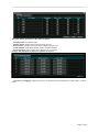
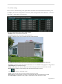
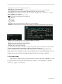
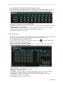
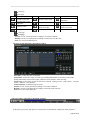
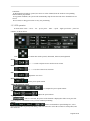
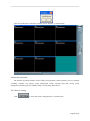
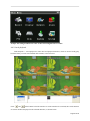
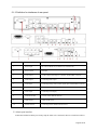
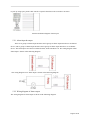
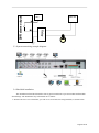
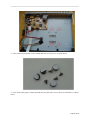
H.264 Digital Video Recorder Operation Instruction Statement: Copyright ©2010 Any extraction, reproduction or distribution of this manual in part or in whole by any company or any individual is prohibited without written consent of our company. The content of this manual will be updated at any time without notice as a result of product version upgrade or other reasons. Except otherwise specified, this manual is only used for application guidance, and all descriptions, information and recommendation in this manual will not constitute any expressed or implied warranty. Page 2 of 49 Precautions: 1. This video recorder is powered by utility power through DC12V adapter, please check the power supply of power socket to see if it meets the requirement of the adapter before installation is carried out; 2. Never place the video recorder at humid place or place subject to rain; 3. The video recorder should be installed at a place without strong vibration; 4. The video recorder should be installed at a place without direct sunlight and far away from heat source and high temperature; 5. When the video recorder is installed, its rear panel should be more than 15cm away from other object or wall to facilitate heat emission by fan; 6. Allow the video recorder to work within the temperature, humidity, and voltage ranges permitted by the technical criteria; 7. Never store chemicals from which corrosive and volatile gas may be created in the place where the video recorder is installed, lest the service life of video recorder will be affected; 8. The video recorder should not installed where there are many dusts, and the surrounding environment should be kept clean; 9. When the video recorder is used, correct grounding should be ensured; 10. When the video recorder is installed, correct connection to other devices should be ensured; 11. Please purchase hard disk from formal channel, so as to suit long term, mass data read-write requirement of DVR; Page 3 of 49 Contents Chapter I: Introduction .................................................................................................................... 6 1.1 Main features ........................................................................................................................ 6 1.2 Product features ................................................................................................................... 6 1.1.1 Performance parameters ........................................................................................... 6 1.1.2 Basic working parameters ........................................................................................ 8 Chapter II: Environmental adaptation ............................................................................................. 8 Chapter III: Operation manual of main frame ................................................................................. 9 3.1 Remote control ..................................................................................................................... 9 3.2 Mouse operation................................................................................................................. 10 3.3 System operation ............................................................................................................... 11 3.3.1 User login ........................................................................................................................ 11 3.3.2 Menu operation ............................................................................................................... 12 3.3.3 Record setting ................................................................................................................. 12 3.3.4 Site setting ...................................................................................................................... 13 3.3.5 Network setting ............................................................................................................... 16 3.3.6 Alarm setting ................................................................................................................... 20 3.3.7 PTZ control...................................................................................................................... 22 3.3.8 Hard disk management ................................................................................................... 23 3.3.9 Record backup ................................................................................................................ 23 3.4 System setting ........................................................................................................................ 24 3.5 Preview ................................................................................................................................... 27 3.5.1 Record control ................................................................................................................. 27 3.5.2 Record playback ............................................................................................................. 28 3.5.3 PTZ operation ................................................................................................................. 30 Chapter IV: IE operation manual .................................................................................................. 31 4.1 Functional characteristics .................................................................................................. 31 4.2 Constraint condition ........................................................................................................... 31 4.3 User login ........................................................................................................................... 31 4.4 Interface operation ............................................................................................................. 32 4.4.1 Remote setting ................................................................................................................ 32 4.4.2 Local playback ................................................................................................................ 33 4.4.3 Remote playback ............................................................................................................ 34 4.4.4 Preview configuration switching...................................................................................... 35 4.4.5 Listening .......................................................................................................................... 35 4.4.6 Snapshot ......................................................................................................................... 35 4.4.7 Log .................................................................................................................................. 35 4.4.8 Group management setting ............................................................................................ 36 4.4.9 Working hard disk ........................................................................................................... 37 4.4.10 Group management switch ........................................................................................... 37 4.4.11 Preview channel setting ................................................................................................ 37 4.4.12 Record ........................................................................................................................... 38 4.4.13 PTZ control.................................................................................................................... 38 Chapter V: DVR installation guidance .......................................................................................... 39 5.1 Definition for interfaces of front and rear panels .................................................................. 39 5.1.1 Definition for interfaces of front panel ............................................................................. 39 5.1.2 Definition for interfaces of rear panel .............................................................................. 40 5.2 Alarm post interface ............................................................................................................. 40 5.2.1 Alarm input & output ....................................................................................................... 41 5.2.2 Wiring diagram of alarm output....................................................................................... 41 5.3 System networking example diagram: ................................................................................. 42 5.4 Hard disk installation ............................................................................................................ 42 Chapter VI: FAQ ........................................................................................................................... 45 Page 4 of 49 Introduction This manual describes a 4/8 channel embedded digital video recorder and its detailed specifications, details the functions and application precautions for each module of the device, as well as the definitions for the signals of each connector on the rear panel. Chapter I Introduction. Product functions and main features are briefly introduced. Chapter II Environmental adaptation Chapter III Operation manual of main frame. Including functional introduction for the press keys of remote control, and the operation function corresponding to each menu interface and the meaning of each option setting are explained in details. Chapter IV Remote monitoring software. The operation function corresponding to each IE menu interface and the meaning of each option setting are explained in details. Chapter V DVR installation guidance. Signal arrangement and connectors of rear panel are detailed; the definition for the signal of each external cable; the definition of front panel and the definition of each interface are also detailed. Chapter VI FAQ. Page 5 of 49 Chapter I: Introduction 1.1 Main features This DVR series is a 4/8 channel real time CIF high resolution digital video recorder. It features real time monitoring, local recording, playback, supporting 3-bit-stream remote network monitoring, data backup, parameter setting, supporting motion detection alarm, supporting USB mouse etc functions. 1.2 Product features Video compression format is standard H.264 Two USB interfaces, 2 for data backup, 1 for mouse operation 16-bit true color translucent graphic menu interface, menu option notation prompt 4/8 channel synchronous playback Two-stage user authority management Support multi-picture real time browse, parameter setting, backup or record playback to local device by network. 1.1.1 Performance parameters Type 4 4 Compression standard H.264 Picture input 1.0Vp-p/75Ω, BNC×4 Picture output 1.0Vp-p/75Ω, BNC×1; VGA×1 Resolution Frame rate Preview: D1 Record: full CIF full real time or full D1 non-real time PAL : 100 Fps(CIF) NTSC : 120 Fps(CIF) 1.0Vp-p/75Ω, BNC×4 Preview: D1 Record: 1D1+3CIF full real time or full D1 non-real time 8 1.0Vp-p/75Ω, BNC×8 Preview: D1 Record: full CIF full real time, or full D1 non-real time PAL : 200 Fps(CIF) NTSC : 240 Fps(CIF) Audio input RCA×1 RCA×4 Audio output RCA×1 Audio codec ADPCM Record mode Manual record, scheduled record, motion detection record and external alarm record Simplex/duplex /triplex Triplex (record, playback, network transmission) Network interface RJ45 (10M/100M self-adapting) PTZ control None Support Page 6 of 49 Communication interface Number of hard disk RS485×1,USB2.0×2 1 SATA hard disk (up to 2T) Mouse USB mouse Remote control Optional Power supply 12V/3A Appearance description DVR-16 appearance 2 SATA hard disk (up to 2T for single hard disk) Yes DVR-22 appearance Page 7 of 49 1.1.2 Basic working parameters Item Input voltage Video input impedance Video output SATA interface of hard disk Working temperature Working parameters 12V DC 12V. 75Ω The video input impedance of each channel is 75Ω. 1Vp-p Output one 1Vp-p CVBS analog signal. -10----50℃ Two SATA interfaces, support SATA hard disk with mainstream capacity It is environmental temperature under good ventilation condition. 0—2V It is low level alarm. 5V-30v It is high level alarm. Description I/O interface RS485 serial port Support PTZ protocol Pelco-D, Pelco-P Chapter II: Environmental adaptation In order to ensure safe application of DVR and obtain satisfactory service performance, prolong the service life of device, customer should fully consider the following factors when install the device: 1) When the device is installed and operated, all specifications of electronic product and the requirements of vehicle and other connecting device should be followed; 2) Power supply and grounding: Never use wet hand to touch power supply and video recorder. Never drop liquid on video recorder, otherwise short circuit inside device or fire may be resulted. Never pile other object on video recorder. Use soft dry cloth to clean video recorder, never use chemical solvents. After the power cable of video recorder is connected to power socket, there is still voltage inside the device even if the video recorder has not been started. If the device is not to be used for long term, it is preferred to fully disconnect the power supply of video recorder, and unplug the power cable from the power socket. Page 8 of 49 Chapter III: Operation manual of main frame In the operation of this device, the Enter key on remote control has the same function as the left click of mouse. 3.1 Remote control Remote control is a minor input device to browse system interface. The function keys of remote control: For single remote control operating multiple DVRS, please refer to 3.4. No. English name 1 【Power】 Operation description 【DEV】 3 【MENU】 4 【ESC】 English name Power ON/OFF Device selection 2 No. Operation description 9 【ENTER】 Confirm operation Switch edit area (time, date, IP address etc) In preview state, switch between full screen/multi-window Enter select state of list box, confirm list selection Select/deselect check box 10 【MUTE】 Mute enabled/disenabled 11 【LENS/VOL-】 12 【LENS/VOL+】 13 【0~9 10+】 14 【FN】 15 【 16 【PTZ】 Enter into main menu Close soft keyboard Close current window Exit current control Return to previous menu Exit select state of list box In preview state, enter/exit PTZ control Slow playback, 1/2×, 1/4×, 1/8×, 【 】 【 】 【 】 single frame play Fast playback, 2×, 4×, 8× playback 5 Stop play 【 】 Start play in search state, play/pause Full screen/multi-window playback 【 6 】 【REC】 mode switching Record control Lens control, volume reducing, number decreasing Lens control, volume increasing, number increasing Number input preview state, zoom in corresponding channel in full screen Pop up control 1/4/8/9 preview window mode 】 switching Enter into PTZ control interface Open search in playback interface, 7 【SEARCH】 long press for 5 seconds to switch between VGA and monitor output. Page 9 of 49 3.2 Mouse operation Mouse is the main input device to browse system menu. Note: except stated otherwise, all system functions in this manual are described by using mouse input operation. Mouse application of this system: 1)Insert USB mouse to the USB mouse port on the front panel of this system or the USB interface at the bottom of rear panel. Note: only the USB port at the top of rear panel is specially used for data backup by U-disk. Never insert U-disk on the bottom USB interface of rear panel. When there is a USB interface on the front panel, never connect USB deice here while the bottom USB interface of rear panel has USB device connected; otherwise, only one device can be detected. Figure 1.0 connect USB mouse to the bottom USB port of rear panel 2)The operation of mouse key is as follow: ·Left key: single click left mouse key on the functional menu option icon to enter the setting page of the menu; double click left mouse key in real time monitoring picture or playback picture will zoom in the image of certain channel, double click left key again to return to the monitoring and playback of multi-channel picture. ·Right key: in real time preview picture, single click right mouse key to enter the main menu of system. In menu page, single click right mouse key to return to previous page. 3)Roller in the middle of mouse: no function at all. Figure 1.1 Mouse key operation Page 10 of 49 3.3 System operation 3.3.1 User login 1. Start the system Power ON/OFF: Connect power cable to the DC12V port on the rear panel of this system. When the system is started, it will execute a basic system inspection and run initial load sequence. After few minutes, the system will load real time display diagram. Password Note: in default condition, password is disabled in system. When you enter any system menu, no password is required. But, for the sake of safety, we strongly recommend you to use password menu to enable and set the password of the system. Note: 1)When the main frame is powered on, if no hard disk is installed on the device, or the installed hard disk is not detected during starting up, or the installed hard disk hasn’t been formatted on the local device, then the following dialog box will be displayed on video preview picture after starting up. 2)Newly installed hard disk can be used normally only after being formatted through local device. New hard disk can be detected automatically during starting up and it will prompt you to format hard disk; if it is required to format hard disk in the system, the procedure is as follow: main menu>hard management>format hard disk or right key shortcut menu>system information>hard disk management 2. System login Open main menu: Single click right key on any position of screen, and select main menu (mouse operation), or press menu/exit button on remote control or front panel of system. Note: if password is enabled in the system, you need to select your user name, and input 6-digit numeric password, so as to open main menu. User: user can select authorized user name in user check box. Password: input the corresponding password of the user name. Page 11 of 49 3.3.2 Menu operation The main menu includes『Record setting』,『Site setting』,『Network setting』,『Alarm setting』,『PTZ control』and『Hard disk management』,『Record backup』,『System setting』items, as shown below: Prompt: the settings to all submenus below are valid only after【Save】is pressed; the settings are invalid when you exit this page directly without pressing Save. 3.3.3 Record setting Move cursor to『Record setting』item (glass framed icon means selected), press【OK】key to enter the setting interface of the item, record setting includes main stream – sub stream – schedule, as shown below: The setting page of main stream is described as follow: Resolution: D1-HD1-CIF optional Frame rate: 2-25 frames optional Coding: fixed stream and variable stream optional Picture quality: 5 steps adjustable Prerecording: set the length of prerecording time before alarm occurs Mode: schedule record, manual record, close record optional Prompt: when encoding is set as fixed stream, picture quality options are: 30M/H(64K)-60M/H(128K)-120M/H(256K)-240M/H(512K)-480M/H(1M) When encoding is set as variable stream, picture quality options are: general – acceptable – good – very good – best Page 12 of 49 The setting page of sub stream is described as follow: Resolution: CIF-QCIF optional Frame rate: 2-5 frames optional Coding: fixed stream and variable stream optional Picture quality: 4 steps optional Prompt: when encoding is set as fixed stream, picture quality options are: 30M/H(64K)-60M/H(128K)-120M/H(256K)-240M/H(512K) When encoding is set as variable stream, picture quality options are: general – acceptable – good – very good The setting page of schedule is described as follow: Channel: select the channel to be set Schedule type: timing record, video alarm, external alarm optional Select-remove: select means schedule record is enabled. Remove means schedule record is disabled. Copy to: select the channel(s) to be copied to Copy: execute the copy parameter Prompt: black pane means the record schedule type has no function, blue pane means it has function. 3.3.4 Site setting Move cursor to『Site setting』icon item (glass framed icon means selected), press【OK】key to enter the setting interface of the item, site setting includes basic parameter – video parameter, as shown below: Page 13 of 49 The page of basic parameter is described as follow: Channel name: set channel name Display name: whether name is displayed in preview Record state: whether record state icon is displayed in preview Audio channel: bind audio channel number with this channel Preview patrol: set the channel to be added to preview patrol Prompt: the time interval of preview patrol is in second The page of video parameter is described as follow: Character overlapping: adjust the positions of channel name and timestamp on video image, as shown below: Page 14 of 49 Zone coverage: user can mask certain zones in the picture; up to 4 zones can be set, as shown below: Prompt: up to 4 zones can be masked in zone coverage Image color: adjust the brightness, chromaticity, saturation and contrast of channel; click “Default” button to restore to default setting Page 15 of 49 3.3.5 Network setting Move cursor to『Network setting』item (glass framed icon means selected), press【OK】key to enter the setting interface of the item, network setting includes basic parameter – PPPOE/DDNS – additional function, as shown below: The page of basic parameter is described as follow: Address mode: static, DHCP (dynamic IP obtained), PPPoE optional IP address: current network IP address of system Page 16 of 49 Subnet mask: current subnet mask of system Default gateway: current default gateway of system Preferred DNS: current preferred DNS of system Backup DNS: current backup DNS of system Server port: data and image transmission port number HTTP port: HTTP port, in general, default value is adopted: 80. If administrator has change the WEB port to other port such as: 8088, then add port number after IP, when it is required to access the device through IE, input in address field:http://192.168.1.118:8088 Mobile phone port: mobile phone data and image transmission port number The page of PPPoE/DDNS is described as follow: PPPoE/account: set PPPoE account PPPoE/password: set PPPoE password DDNS/server: set DDNS server supplier, 3322 and dyndns optional DDNS/account: set DDNS account DDNS/password: set DDNS password Local host domain mane: set DDNS domain name Refresh: test DDNS to see if it is successful Steps for the enable of PPPoE function: Step 1: enter “main menu->network setting->PPPoE/DDNS” page, fill in correct PPPoE account and password Step 2: enter “main menu->network setting->basic parameter” page, select PPPoE in address mode, so as to enable PPPoE dialing. Steps for the enable of DDNS function: Step 1: application of DDNS service The host name, user name and password of DDNS must be registered on DDNS server; take 3322 for example to guide DDNS registration: Input http://members.3322.org/ in the address field of IE to carry out the registration of new user, Page 17 of 49 1) After user registration information is filled in, click Submit. 2) After a certain period of time, you will receive an email from 3322, so that initial password is obtained; 3) Use the registered user name and obtained password to log in http://members.3322.org/, click “My console”, after the page of domain name management is entered, there is a list of domain name classification at the left side of the page, click “New” under dynamic domain name, the following figure appears: 4) Input a host name that you want to establish, click OK. In this way your DDNS registration is completed. Step 2: enter “main menu->network setting->PPPoE/DDNS” page, select DDNS server and fill in corresponding account, password and local host domain name. Step 3: click Refresh button to check parameters to see if they are correct. Step 4: click DDNS enable box to complete the enable of DDNS function. Page 18 of 49 The page of additional function is described as follow: EMAIL: set EMAIL sending as shown below Server: select address of mailbox server User: corresponding mailbox address of above Smtp server Password: password of above mailbox Receiver 1: mailbox address of receiver 1 Receiver 2: mailbox address of receiver 2 FTP: set FTP as shown below Server: FTP server address Server port: FTP server port User: user name of FTP server Password: password of FTP server UPNP: set UPNP device Page 19 of 49 3.3.6 Alarm setting Move cursor to『Alarm setting』icon (glass framed icon means selected) in main menu interface, press 【OK】key to enter the setting interface of the item, alarm setting includes motion detection – video loss – alarm input – alarm output, as shown below: The page of motion detection is described as follow: Enable: enable motion detection function Sensitivity: adjust the sensitivity of motion detection Zone: set effective space zone of motion detection as shown below Prompt: the selected white zone means that it is not the detection zone of motion detection Schedule: set affective time zone of motion detection, see 3.3.3 schedule setting page for setting method Alarm output: set bound alarm output Delay: set the delay time when the inspection will be done again after motion detection occurred Record: set the channel of correlating record after motion detection occurred Click to enter the following menus Delay: set the time to delay record after motion detection occurred PTZ control: set triggering the operation of correlated PTZ after motion detection occurred Screen prompt: set whether screen prompt is needed after motion detection occurred Page 20 of 49 EMAIL: set whether email is needed to be sent after motion detection occurred Buzz: set whether buzz is needed to sound after motion detection occurred FTP: set whether snapshot is needed to be sent to designated FTP server after motion detection occurred The page of video loss is described as follow: Enable: enable video loss function Schedule: set the effective time zone of video loss Alarm output: set bound alarm output Delay: set the delay time when the inspection will be done again after video loss occurred Record: set the channel of correlating record after video loss occurred Delay: set the time to delay record after video loss occurred PTZ control: set triggering the operation of correlated PTZ after video loss occurred Screen prompt: set whether screen prompt is needed after video loss occurred EMAIL: set whether email is needed to be sent after video loss occurred Buzz: set whether buzz is needed to sound sent after video loss occurred FTP: set whether snapshot is needed to be sent to designated FTP server after video loss occurred The page of alarm input is described as follow: Enable: enable alarm input function Level: adjust the effective level of alarm input Schedule: set the effective time zone of alarm input Page 21 of 49 Alarm output: set bound alarm output Delay: set the delay time when the inspection will be done again after alarm input occurred Record: set the channel of correlating record after alarm input occurred Delay: set the time to delay record after alarm input occurred PTZ control: set triggering the operation of correlated PTZ after alarm input occurred Screen prompt: set whether screen prompt is needed after alarm input occurred EMAIL: set whether email is needed to be sent after alarm input occurred Buzz: set whether buzz is needed to sound sent after alarm input occurred FTP: set whether snapshot is needed to be sent to designated FTP server after alarm input occurred The page of alarm output is described as follow: Enable: enable motion detection function Type: adjust the type of alarm output, normal open type and normal close type optional 3.3.7 PTZ control Move cursor to『PTZ control』icon (glass framed icon means selected), press【OK】key to enter the setting interface of the item, PTZ control includes PTZ control, as shown below: The page of PTZ control is described as follow: Page 22 of 49 Address: set the address of corresponding ball machine Baud rate: select the baud rate used by corresponding ball machine Protocol: select the protocol of ball machine with corresponding brand type 3.3.8 Hard disk management Move cursor to『Hard disk management』item (glass framed icon means selected), press【OK】key to enter the setting interface of the item, as shown below: The page of hard disk management is described as follow: Hard disk space: total space of hard disk Residual space: total unused space of hard disk Hard disk state: when it is formatted, the state is normal; otherwise, the state is unformatted Alarm space: when the residual space of hard disk is less than this value, a “Disk” prompt is displayed on the top right corner of preview interface, the unit is G When disk is full: operation when disk is full: stop record and overwrite record optional Format operation: Step 1: select the hard disk to be formatted. Step 2: click Format button to format the hard disk. 3.3.9 Record backup Move cursor to『Record backup』icon (glass framed icon means selected), press【OK】key to enter the setting interface of the item, record backup includes backup, as shown below: The page of backup is described as follow: Channel: the channel to which record video file belongs Start stop time: the start time and stop time of record video file Page 23 of 49 File type: the reason of creating record video file Size: the size of record video file Search date: set the time range of search, green background means record video existed, blue background means certain selected date; underline means the date of the same day. Search type: set the range of record events to be searched: “timing record”, “video alarm”, “external alarm”, “manual”, “all” optional. Search channel: set channel range of search :select the record video file to be backed up <<:first page <:last page >:next page >>:last page Search: execute search operation according to set search condition Backup: execute backup of record video file according to selected record video file, as shown below Device: select available backup device: FTP and USB device optional File: name of record video file to be backed up Process: process of backing up record video file Start: start to back up record video file Cancel: exit or cancel record backup User can view the backed up record file on computer, the general format of record file is: channel number + start year month day hour minute second + end time hour minute second.264. Prompt: during the process of backup operation, the “process” of record backup window will display the process of backup in real time; if the backup operation is cancelled during the process of backup, then the system will automatically pop up prompt after the backup is completed. 3.4 System setting Move cursor to『System setting』icon (glass framed icon means selected), press【OK】key to enter the setting interface of the item, site setting includes basic parameter – user management – automatic maintenance – upgrade, as shown below: Page 24 of 49 The page of basic parameter is described as follow: Local host name: client side or system name displayed by CMS Local host number: it is used when multiple DVRs are controlled by a remote control Enable remote control: aim the remote control at the DVR to be controlled, press DVE, input device number, and then press ENTER. The local host number is 0 by default; the remote control can directly control the DVR Close remote control: aim the remote control at the DVR to be controlled, press DVE, input device number, and then press ENTER, then the DVR will not be controlled by the remote control. System: two modes: PAL and NTSC. User can select himself according to video recorder. Language: support multiple languages Resolution: set the resolution of display Primary device: set menu output to switch between VGA and CVBS. Date: set the year-month-day of system Time: set the hour-minute-second of system The page of user management is described as follow: Type: except that admin is administrator, others are ordinary users Add: add new user name, password and authority as shown below Page 25 of 49 Delete: delete existed user in the system; except admin, guest, other users can be deleted. Modify: modify the user name, password and authority of existed user in the system. The page of automatic maintenance is described as follow: Factory setting: restore to default factory setting Restart system: set the period and time point for the restart of system Page 26 of 49 The page of upgrade is described as follow: File: file mane of upgrade file Version: version of upgrade file Hard disk space: size of upgrade file Refresh: refresh USB or FTP file list Upgrade: select the file to be upgraded, click Upgrade to carry out software upgrade to the system 3.5 Preview After normal login of device, preview picture is entered directly. The preview picture displays toolbar and the name and state of each channel. The page for the buttons of toolbar is described as follow: Enter main menu Hide toolbar Select the channel to be listened in or mute on site Set the record mode of each channel Short cut playback, play back the record of latest time and start from the beginning time point of that day Operation interface of control PTZ Enable patrol or close patrol / / 1 3 It is 1-channel screen mode, 4-channel screen mode, and 9-channel screen mode The page for the icons of channel state is described as follow: When video loss occurred in the channel, When recording occurred in the channel, this 2 LOSS this symbol is displayed on the channel symbol is displayed on the channel picture picture When dynamic detection occurred in the When external alarm occurred in the channel, this symbol is displayed on the 4 channel, this symbol is displayed on the channel picture channel picture 3.5.1 Record control User can select record mode according to his requirements. For different mode of record, when recording occurred in the channel, record symbol will be displayed on the channel picture. Prompt: for record operation, user is required to have “Record” operation authority; before carry out this operation, please confirm that hard disk has been installed in the video recorder and has been formatted correctly. Page 27 of 49 The description for entering record operation page is as follow: Click right mouse in preview state and select “Record control” in pup up menu, or enter into record operation interface through “shortcut menu” → “Record control”. Press “Record/REC” key in preview mode can also enter into record control operation interface directly, as shown below: Figure 3-4 The page of record operation is described as follow: Schedule record: set the channel to be recorded according to timing, dynamic detection and alarm setting conditions set in record setting. Manual record: the highest priority level, after manual button is executed, all corresponding channels execute manual record, regardless of state that each channel is in. Stop record: all channels stop record. 3.5.2 Record playback The system has two methods of record playback: fast playback and record search; when record search is carried out, you can search file and select playback; you can also play back by time. The fast playback page is described as follow: In preview picture, press “PLAY” key or single left click mouse on “ ” position in toolbar to play back the video one minute before current time. The video search page is described as follow: In preview picture, press “Search” or “shortcut menu” → “Record search” to enter record search. The file playback page is described as follow: Channel: the channel to which record video file belongs. Start stop time: the start time and stop time of record video file File type: the reason of creating record video file Size: the size of record video file Search date: set the time range of search, green background means record video existed, blue background means certain selected date; underline means the date of the same day. Search type: set the range of record events to be searched: “timing record”, “video alarm”, “external alarm”, “manual”, “all” optional. Search channel: set channel range of search Page 28 of 49 :first page :last page Button Description Button Description Button Description Fast backward, 4 steps adjustable Switch to play state Switch to pause state Fast forward, 4 steps adjustable Single frame backward Single frame forward Volume switch Play back the record video of last day Play back the record video of next day Hide play control bar Exit playback :next page :last page Search: execute search operation according to set search condition Backup: execute record playback according to selected record video file Exit: exit record search dialog box The page of time playback is described as follow: Figure 3-6 Start time: set the start time of playback. Search date: set the time range of search, green background means record video existed, blue background means certain selected date; underline means the date of the same day. Search type: set the range of record events to be searched: “timing record”, “video alarm”, “external alarm”, “manual”, “all” optional. Search channel: set channel range of search Search: execute search operation according to set search condition Backup: execute record playback according to selected record video file Exit: exit record search dialog box The page of play control bar is described as follow: Play control bar 1: The play speed, time, play process of current file etc information is displayed on the playback Page 29 of 49 control bar. 2: When playback audio is opened, use mouse to select channel, then the audio of corresponding channel will be played back. 3: In general condition, the system will automatically skip all time intervals where channels have no record. 4: Use mouse to drag process bar to carry out positioning. 3.5.3 PTZ operation It means PTZ zoom – focus – iris – preset point – name – speed – high speed PTZ – patrol etc controls, as shown below: Click to control PTZ strike upward, downward, leftward, and rightward Zoom: “+” “-” is used to adjust zoom in and zoom out of lens Focus: “+” “-” is used to realize focus function Iris: Adjust the size of iris Preset point of PTZ: Set the preset point of PTZ Adjust the following 3 keys , , to complete the preset point of PTZ Speed: Adjust the speed of PTZ High speed PTZ: After it is selected, the picture of the channel is displayed in full screen; press left mouse button to control PTZ to carry out fast rotation positioning. Patrol: Select serial number in patrol dialog box, select preset serial number in preset point dialog, click time interval to select the seconds to switch patrol, and then click Set. Page 30 of 49 Chapter IV: IE operation manual 4.1 Functional characteristics Network operation is used to install software through IE browser of the operation system, which is simple and easy; DVR supports C/S, B/S structure, LAN and WAN access, and supports IP and domain name access at the same time. Support user to modify service port, and support PPPOE, DHCP functions at the same time, support 4 channels audio video record function. 4.2 Constraint condition In order to ensure PC to stably access this DVR product, it is recommended to use Windows XP, Windows Vista operation system; and IE6.0, IE7.0 browsers are recommended. 4.3 User login Input current IP of the device in IE, if the WEB port number is set as (80), then directly input IP address in IE address field; if the WEB port is modified as a port other than 80, then the port number should be added after IP address; for example: the IP of device is 192.168.1.118, set the port as 8088, then input: http://192.168.1.118:8088 to access the device. Under the condition that the network is connected, IE will prompt you to install control to be downloaded to your PC, as shown below: Click “Install ActiveX control”, after the download of control is successful, it will automatically enter into login interface, as shown below: You can select English – Simplified Chinese – Traditional Chinese – Français (French) – espaňol;-a (Spanish) – Portugues (Portuguese) – Poccию (Russian) User name: input authorized user name Password: input the corresponding password of the user name Network environment: LAN/WAN, select according to the network connection type between your computer and DVR. After the input is completed, click shown below, then click to enter into IE interface. If the input is wrong, as to input again. Page 31 of 49 After successful login, it will enter real time preview interface, as shown below: 4.4 Interface operation The interface operation includes remote setting, local playback, remote playback, preview, listening switching, snapshot, log enquiry, group management setting, working hard disk setting, group management switching, preview channel setting, record setting, PTZ control. 4.4.1 Remote setting Click to enter into remote setting interface, as shown below: Page 32 of 49 Prompt: the setting method is the same as that of local digital video recorder 4.4.2 Local playback Click Playback -> Local playback to enter into local playback interface, which is used to locally play back PC history records stored in hard disk of DVR, as shown below: Click and at the bottom left of the interface to set the month to be searched, the record situation of current month is displayed on the calendar interface, as shown below: Page 33 of 49 The date in bold front means that day has records existed; blue frame means selected date, directly click the date to search the record information of the same day. For example: there are records existed in 22nd, 25th, 26th April 2011, the date of current search is 26th April, as shown below: Local playback steps Step1: select the date having video data in zone 1 (note: the date having video data is shown in bold front). Step 2: select the time interval having video data in zone 2 (note: the time interval having video data is shown in black). Step 3: click Play button, other operation methods are the same as that of local DVR. The following play buttons will appear when playback is carried out. Play Pause Stop play Fast backward Fast forward Frame forward Frame backward Audio control of playback Close 4.4.3 Remote playback Click remote playback -> remote playback to enter remote playback interface, which is used to locally play Page 34 of 49 back PC history records stored in hard disk of DVR. See section 3.5.2 for operation method. 4.4.4 Preview configuration switching Click button, click icons to switch between /4-picture, /9-picture, /10-picture, /13-picture, /16-picture, Prompt: right click mouse in picture, click full screen to switch. /6-picture, /25-picture. 4.4.5 Listening Click , then it shows . Listening means monitor remote audio. 4.4.6 Snapshot Click to snapshot single image, the file will be saved on preset path, as shown below: 4.4.7 Log Click to enter into log information interface, as shown below: Type: log type of the event. User: user operator of the event Start time: the time when the event log occurred Search date: set the time range of search, green background means record video existed, blue background means certain selected date; underline means the date of the same day. Page 35 of 49 System: Parameter modification: set search range to include parameter modification event Playback: set search range to include record playback event Backup: set search range to include backup event Alarm: set search range to include alarm event Error: <<:first page <:last page >:next page >>:last page Search: execute search operation according to set search condition Exit: exit record search dialog box 4.4.8 Group management setting Click to enter into group management interface, as shown below: Select server: New group name: set the name of new group New group: build a new group Save group: save a group Delete group: delete a group Search server: Server IP: Server port: the port transmitting video and control data in digital video recorder User name: user name for network access Password: corresponding password of user name for user access Search: search the digital video recorder server conforming to conditions Page 36 of 49 Prompt: after Search is clicked, if the device exists, then it will be shown in zone 1, single click mouse and drag or single click to select the channel to be added, right click mouse to add device, then channels added successfully will be shown in zone 2, right click mouse on zone 2 to switch bit stream, delete selected channel. If it is required to add new group, click New group, then add network channel; after such add is completed, click Save group, and exit. 4.4.9 Working hard disk Click to enter into Browse computer dialog box, as shown below: Prompt: working hard disk means the path position to save record file, backup file, snapshot file. 4.4.10 Group management switch Click to enter into fast switching network group, as shown below: 4.4.11 Preview channel setting Click to open or close the preview of corresponding channel, as shown below: Page 37 of 49 4.4.12 Record Click to open or close the record of corresponding channel, as shown below: 4.4.13 PTZ control The operation method is similar as that of local DVR, see section 3.5.3. Page 38 of 49 Chapter V: DVR installation guidance 5.1 Definition for interfaces of front and rear panels 5.1.1 Definition for interfaces of front panel Key name Symbol Function introduction Power indicator POWER Power indicator lit means DVR is energized (including shut down state) Running light RUN Indicate that DVR runs normally after starting up Record indicator REC Indication of record enabled NETWORK Light indication for normal connection of network PLAYBACK Light indication for playback state of DVR Alarm indicator ALARM Light indication of alarm state POWER key POWER Power switch, press and hold for 3 seconds to shut down Menu key MENU Press Menu key to enter into menu interface Escape key ESC Exit current interface Function auxiliary key FN Auxiliary function, which is equivalent to the right mouse key, it can pop up input box when input is required. PTZ control key PTZ Enter into PTZ control interface Record key SEARCH Network indicator Playback indicator search Record state key Fast key Fast key backward REC Open search in playback interface, long press it for 5 seconds to switch between VGA and monitor output. Enter into record state setting interface, you can select: auto record, manual record, stop record SLOW/- Fast backward playback, 2×, 4×, 8× playback FAST/+ Fast forward playback, 2×, 4×, 8× playback Play key PLAY/PAUSE Start playing in search state, play/pause Stop key STOP Stop playback of record Switch key SWITCH Switch between 1/4/8/9/16-picture Direction key ▲.▼.. Switch currently activated control, move upward, downward, leftward and rightward Enter key ENTER Confirm operation forward Page 39 of 49 5.1.2 Definition for interfaces of rear panel No. Physical interface Interface description 1 Power input DC 12V (4-channel 3A, 8-channel 3A, 16-channel 5A) 2 Power switch ON/OFF 3 Video output 1 video output connecting TV or monitor, standard BNC connector 4 Audio output Connecting audio output 5 Video input Connecting analog video (camera) signal input, standard BNC connector 6 Audio input Connecting active audio signal 7 VGA output Connecting VGA display 8 Network interface Used to connect Ethernet network 9 USB interface USB2.0/USB mouse 10 RS485 interface Connecting PTZ etc RS485 interface device 5.2 Alarm post interface Connection method of alarm post: firstly strip the cable to be connected, then use a small screwdriver Page 40 of 49 to jack up orange part, put the cable into the receptacle then loosen the screwdriver to fasten. Interface definition diagram of alarm post 5.2.1 Alarm input & output There are 8 groups of alarm input interfaces and 2 groups of alarm output interfaces in 8-channel device; and 16 groups of alarm input interfaces and 2 groups of alarm output interfaces in 16-channel device. The alarm input can connect to infrared alarm, smoke transducer etc. The wiring diagram of DC alarm input is shown in the following diagram. The wiring diagram of AC alarm input is shown in the following diagram. 5.2.2 Wiring diagram of alarm output The wiring diagram of alarm output is shown in the following diagram: Page 41 of 49 220V AC Relay DVR alarm output 12V 24V 5.3 System networking example diagram: 5.4 Hard disk installation The installation of hard disk should be done by professional staff to prevent machine and hard disk from damage. The installation steps of hard disk are as follow: 1)Remove the face cover of machine, you will see 4 screw holes for fixing hard disk, as shown below: Page 42 of 49 2)Take out shock pad and fix screws of hard disk from accessory box, as shown below: . 3)Tear off the sticky paper of shock pad and stick the pads on the 4 screw holes of main frame, as shown below: Page 43 of 49 4)Align the screw holes on the side of hard disk with circuit board below with the holes of shock pads to facilitate fixing by screws, as shown in the diagram. 5)Fix the hard disk from bottom by using screws, screws should drive into the screw holes of Page 44 of 49 hard disk through shock pads, as shown in the diagram. Note: newly installed hard disk must be formatted on the main frame before it can be used to record normally. Chapter VI: FAQ If the problem you met is not listed in the content below, please contact local customer service personnel or call the customer service of headquarter to consult, we will serve for you with all our heart. 1. Ask: after starting up, digital video recorder can’t start normally Answer: possible reasons: 2. 1 Input power supply is incorrect 2 The contact of switching power cable is bad 3 Switching power supply is bad 4 Program update is wrong 5 The main board of digital video recorder is bad Ask: digital video recorder will restart automatically or often down several minutes after starting up Answer: possible reasons: 1 Input voltage is unstable or too low 2 Hard disk has bad track or hard disk cable is bad Page 45 of 49 3. 3 The power of switching power supply is not enough 4 The video signal of front end is unstable 5 Bad ventilation, too much dust, the operating conditions of machine are too severe 6 The contact between main board and other auxiliary board is bad 7 Hardware failure of digital video recorder Ask: single channel, multiple channels, all videos have no output Answer: possible reasons: 1 Please check the power supply connecting camera for loose 2 Please check the connecting wire of video output and input on the rear panel of DVR 3 Directly insert the video source into display device to judge if it is the problem of video source or display device 4. 4 Check image brightness to see if it becomes 0, restore to default setting 5 No video input signal or the signal is too weak 6 Preview closed is set in display setting 7 Hardware failure of digital video recorder Ask: can’t record normally after starting up, a “H” is prompted on the interface Answer: possible reasons: 5. 1 Check if DC12V power adapter is adopted by the machine 2 Check if new hard disk has been formatted on the local host 3 The contacts of hard disk power cable, data cable are bad or damaged 4 Hard disk is damaged 5 SATA port of main board is damaged Ask: what’s the meanings of “R” “M” “I” “H” prompted on direct connection picture Answer: 6. 1 “R” means that record is being carried out on the channel 2 “M” means that motion detection is triggered on the channel 3 “I” means that external I/O alarm is triggered on the channel 4 “H” means that the device has no hard disk connected or hard disk failure or disk full Ask: real time image problem, such as video image color, brightness have serious distortion Answer: possible reasons: 1 When BNC is used for output, the selection of PAL system and NTSC system is incorrect, the image will become black and white 2 Digital video recorder and the impedance of monitor not matched 3 Video transmission distance is too long or the fading of video transmission cable is too high Page 46 of 49 4 7. The settings of color, brightness etc of digital video recorder are incorrect Ask: no sound in listening Answer: possible reasons: 1 Check if active pickup and active sound box are adopted, you can judge by directly short the signal cables of both 2 Whether the video channel with audio source connected is activated, you can single click the channel to be in full screen to judge 3 8. Hardware failure of digital video recorder Ask: there is sound in monitoring, but no sound in playback Answer: possible reasons: 9. 1 Setting problem: audio record option has not been opened 2 Whether mute is set in playback interface Ask: time display is wrong Answer: possible reasons: 10. 1 Setting is wrong, or the time is modified but “Modify date & time” is not pressed to validate 2 The contact of battery is bad 3 The service time of battery is too long, please replace the battery Ask: why “Stop record” by clicking right mouse has no function, how to stop record Answer: 1 The “Stop record” key of right mouse is used to stop manual record, it can’t be used to stop the record set in starting record or record schedule 2 If it is required to stop record, please enter into record schedule, set the time interval as no record 11. Ask: motion detection has no function Answer: possible reasons: 12. 1 The setting of motion detection zone is not appropriate 2 The sensitivity is too low Ask: error in DVD/CD rewritable drive/USB device Answer: possible reasons: 13. 1 Data quantity exceeds the capacity of backup device, which will result in CD burning error 2 Backup device is not compatible 3 Backup device is damaged Ask: the remote control can’t control Answer: possible reasons: Page 47 of 49 14. 1 The address of remote control is wrong 2 The distance of remote control is too far or the angle is too deflective 3 The battery of remote control is used up 4 The remote control is damaged or the front panel of video recorder is damaged Ask: can’t login WEB Answer: possible reasons: 1 Check if the network is connected, check if the LINK or 100M LED on panel displays correctly; use ping xxx.xxx.xxx.xxx (the IP address of the DVR) to check if the network is connected 15. 2 Windows XP or Vista operation system is recommended, IE6.0 or IE7.0 browser is adopted 3 ActiveX control is inhibited, please install ActiveX control manually 4 No dx8.1 or above version is installed, upgrade the driver of display card Ask: there is mosaic in network preview picture and record file playback or no image at all Answer: possible reasons: 1 If DVR is accessed through Internet, when IE is used to login, please select “WAN” in “Network environment”, and select appropriate network bandwidth in “Setting > System setting > Network environment” option. 2 16. Please try right key “Close window”, then “Open window” Ask: when setting is carried out at IE end, why “Other user is configuring…” window pops up Answer: possible reasons: 1 This may means that others are setting DVR. Please check if the configuration interface of DVR end is in open state, please exit. 17. Ask: digital video recorder can’t control PTZ Answer: possible reasons: 1 Front end PTZ failure 2 PTZ decoder setting, wiring, installation are incorrect 3 Wiring is incorrect 4 The setting of PTZ in digital video recorder is incorrect 5 PTZ decoder and the protocol of digital video recorder not matched 6 PTZ decoder and the address of digital video recorder not matched 7 When multiple decoders are connected, the farthest end of A B lines of PTZ decoder should be added with a 120 Ω resistor to eliminate reflection and make impedance matching, otherwise unstable PTZ control may be resulted. Page 48 of 49 8 18. The distance is too far Ask: how much capacity is occupied in hard disk by record per hour Answer: 1 2 19. For audio record, about 14Mbyte capacity is occupied for each channel The capacity occupied in hard disk by video record depends on the selection of “Record mode > bit rate”: excellent, good, medium, and also depends on the motion amount of pictures within the time interval; if the picture is still, then the consumption of hard disk is lower; if the picture is motive, then the consumption is higher. When “excellent” is selected, about 320Mbyte capacity is occupied for each channel of video per hour; when “good” is selected, and the pictures are still or small motive, then about 50~100Mbyte capacity is occupied for each channel of video per hour; if the pictures are large motive or many small motive, then about 100~200Mbyte capacity is occupied for each channel of video per hour; when “medium” is selected, and the pictures are still or small motive, about 50~100Mbyte capacity is occupied for each channel of video per hour; if the pictures are large motive or many small motive, then about 100~150Mbyte capacity is occupied for each channel of video per hour; Ask: I/O alarm has no function Answer: possible reasons: 1 Alarm setting is incorrect 2 Alarm wiring is incorrect 3 Alarm input signal is incorrect 4 One alarm device connects to 2 circuits at the same time Page 49 of 49


![CDNXL_60_RETAIL_SALES [MetaTexis] [Final version]](http://vs1.manualzilla.com/store/data/005704456_1-17a983fab827ed2fd4ed28ca910215ca-150x150.png)