1
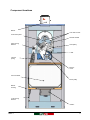
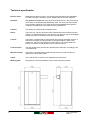
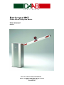
Barrier type MKC
Power-driven rising arm barrier
User manual
Edition 1
BOX 125 S-284 22 PERSTORP SWEDEN
Phone: +46 435 77 95 00 Fax: +46 435 77 95 29
E-mail: [email protected]
www.daab.nu
Contents
Declaration of conformity ..................................................................................................................... 3
Safety instructions ................................................................................................................................ 4
General description............................................................................................................................... 4
Component locations ........................................................................................................................... 5
Technical specification ......................................................................................................................... 6
Mechanical installation ......................................................................................................................... 7
Items to be considered when mounting the barrier ............................................................................ 7
Mounting the boom............................................................................................................................. 7
Electrical connection ............................................................................................................................ 7
Commissioning...................................................................................................................................... 7
Limit position and mechanical stops .................................................................................................. 7
Maintenance and service ...................................................................................................................... 8
Serial number ..................................................................................................................................... 8
Manual release................................................................................................................................... 8
Maintenance instructions.................................................................................................................... 8
Disassembling the barrier................................................................................................................... 8
Descriptions and pictures in this user manual are not binding. DAAB reserves the right to make
product changes without prior notice. These changes may be carried out without updating this user
manual.
2
User manual MKC
Edition 1
Declaration of conformity
According to AFS 1994:8, Attachment 2 A,
Manufacturer:
DAAB Portteknik AB
Box 125
284 22 Perstorp
Sweden
Phone: +46 (0)435 77 95 00
Fax: +46 (0)435 77 95 29
Declares that:
Product:
Power-driven barrier is manufactured in accordance with following harmonised
standards:
AFS 1994:48 (which corresponds to 98/37/EEC)
SS-EN 292-1 ” Safety of machinery - Basic concepts, general principles for design - Part 1: Basic
terminology, methodology”
SS-EN 292-2 ” Safety of machinery - Basic concepts, general principles for design - Part 2: Technical
principles and specifications”
SS-EN 294
” Safety of machinery - Safety distances to prevent danger zones being reached by the
upper limbs”
SS-EN 418
” Safety of machinery - Emergency stop equipment, functional aspects - Principles for
design”
Low voltage directive (LVD) 73/23/EEC
-SS EN 60204-1 “Safety of machinery - Electrical equipment of machines - Part 1: General
requirements”
The directive for electromagnetic compatibility (EMC) 89/3366/EEC with changes 92/31/EEC and
93/68/EEC.
SS-EN 61000-6-3 “Electromagnetic compatibility (EMC) - Part 6-3: Generic standards - Emission
standard for residential, commercial and light-industrial environments”
SS-EN 55014-1 "Electro-magnetic compatibility - Requirements for household appliances,
electric tools and similar apparatus - Part 1: Emission"
SS-EN 55022
"Information technology equipment - Radio disturbance characteristics - Limit
and methods of measurement"
SS-EN 61000-3-2 "Electro-magnetic compatibility (EMC) - Part 3-2: Limits - Limit for harmonic
current emissions (equipment input current up to and including 16 A per
phase)"
SS-EN 61000-3-3 "Electro-magnetic compatibility (EMC) - Part 3: Limits - Section 3: Limitation
of voltage fluctuations and flicker in low-voltage supply systems for equipment
with rated current up to and including 16A"
SS-EN 61000-6-2 "Electro-magnetic compatibility (EMC) - Part 6-2: Generic standards - Immunity for
industrial environments"
SS-EN 61000-4-2 "Electro-magnetic compatibility (EMC) - Part 4-2: Testing and measurement
techniques - Electrostatic discharge immunity test"
SS-EN 61000-4-3 "Electro-magnetic compatibility (EMC) - Part 4: Testing and measurement - Section
3: Radiated, radio-frequency, electromagnetic field immunity test"
SS-EN 61000-4-4 "Electro-magnetic compatibility (EMC) - Part 4: Testing and measurement
techniques - Section 4: Electrical fast transient/burst immunity test - Basic EMC
Publication"
SS-EN 61000-4-5 “Electromagnetic compatibility (EMC) - Part 4: Testing and measurement
techniques - Section 5: Surge immunity test”
SS-EN 61000-4-6 "Electro-magnetic compatibility (EMC) - Part 4: Testing and measurement - Section
6: Immunity to conducted disturbances, induced by radio-frequency fields"
SS-EN-61000-4-8 “Electromagnetic compatibility (EMC) - Part 4: Testing and measurement
techniques - Section 8: Power frequency magnetic field immunity test - Basic EMC
Publication”
SS-EN 61000-4-11 "Electro-magnetic compatibility (EMC) - Part 4: Testing and measurement
techniques - Section 11: Voltage dips, short interruptions and voltage variations
immunity tests"
Perstorp 2003-04-08
/Dan Irwe, Managing Director
User manual MKC
Edition 1
3
Safety instructions
The user manual which is delivered with the barrier should be read through carefully, it contains
important information about safety, commissioning and usage. This user manual is common for
different types of barriers. For electrical connection, setting and specific safety instructions, see user
manual for the control panel. Risk for serious personal injury or material damage can arise if the safety
instructions aren’t followed.
WARNING! Incorrect installation or wrong usage of this product can cause
injury to persons, animals or property.
•
•
•
All the paragraphs for commissioning the barrier must be read to obtain the correct adjustment.
If the barrier is bent or damaged in any way it must be replaced with a new item.
If the length of the barrier is changed or if addition equipment is mounted on the barrier boom, the
barrier must be re-balanced. Contact DAAB for advises.
General description
Intended use
The purpose of the barrier is to control entry and exit of vehicles. It may be a double barrier or a single
barrier. A single barrier consists of a cabinet with a boom and a double barrier consists of two cabinets
with two booms. A motor and gearbox is provided to open and close the barrier. There is a manual
release mechanism to disengage the boom in event of power failure. Balance springs are provided to
balance the arm.
Barrier control
The control panel is normally located in the barrier cabinet, but can be supplied in a separate
enclosure. The EP 103-1 panel is used for a single barrier and an EP 103-2 is used for a double
barrier.
The control panels can be provided with various accessories, e.g. vehicle loops, radio and traffic
lights.
4
User manual MKC
Edition 1
Component locations
Barrier
Limit switch cams
Limit switch plate
Release handle
Upper spring
bracket
Gear pulley
V-belt
Tension
spring
Electric
motor
Control cabinet
Motor pulley
Barrier
housing
Lower spring
bracket
Isolator
User manual MKC
Edition 1
5
Technical specification
6
Electric motor:
Three-phase induction motor in accordance with international IEC standards.
0.37 KW, 1400 rpm, 230/400 V, 50 Hz. Single phase motors are available.
Gearbox:
The gearbox consists of a worm wheel manufactured from alloy bronze and
worm drive of hardened and polished alloy steel. The drive and output shafts
are mounted in ball races. The output shaft is electroplated and the gearbox
housing is manufactured of an aluminium alloy, filled with oil.
Cabinet:
The cabinet is manufactured of stainless steel.
Boom:
The boom is a 100-mm aluminium tube, finished white with red luminous tape
stripes. It is balanced with one or two springs. The gearbox may be disengaged
to allow the boom to be lifted in the event of power failure.
Control:
The barrier is supplied with a control panel which permits automatic closure. A
load sensor prevents crushing injuries. Push-button stations, radios, card
readers etc. may be connected to the control panel. The control panel also
permits connection of vehicle detectors for various functions.
Limit positions:
The limit positions are set with cam operated micro switches. For settings, see
"commissioning".
Mechanical stop:
The barrier is provided with mechanical stop devices in order to achieve a
stable open and closed position.
V-belt:
The V-belt is SPZ 10 section. See "Maintenance instructions".
Marking plate:
Manufacturer's name and address, item number and serial number.
User manual MKC
Edition 1
Mechanical installation
A suitable concrete plinth must be provided for the barrier cabinet and tip rest (if required). The cabinet
is then anchored to the plinth using suitable chemical anchors. A cable duct must be provided through
the centre of the plinth to enable power and control cables to be connected to the control panel.
Items to be considered when mounting the barrier
•
•
•
Place the barrier so that there are no obstacles in its path in either the open or closed positions.
Make sure a cable duct has been provided.
That there is access to the control panel after the barrier has been installed.
Mounting the boom
The boom is clamped to the gearbox output shaft with a stainless steel mounting bracket. This is fitted
as follows:.
1. Loosely attach the clamp with two screws on one side.
2. Insert the boom and close the clamp with a C-clamp until the two remaining holes line up with the
boom fixing plate.
3. Insert the remaining screws and tighten the whole assembly.
Electrical connection
It is important to make sure that the control system is installed according to control panel user manual.
Commissioning
Make sure the area around the barrier is free of obstructions before operation! Once the barrier has
been mechanically assembled and electrically connected, commissioning is carried out in accordance
with the following description and the control panel user manual.
Limit position and mechanical stops
If the pre-set adjustment needs to be altered is this done in the following manner. The mechanical
stops are located on the balance spring arms.
1. Unscrew the adjusting screws far enough so that they do not touch in the ‘end’ positions.
2. Now adjust the limit position cams. The cams are placed on the output shaft. The front cam is for
the closed position, the inner one for the open position. Set the limit positions so that the barrier
opens and closes to the correct positions.
3. Run the barrier to open position. Adjust the mechanical stop with the adjusting screw so that it
touches the stop.
4. Back-off the screw one turn.
5. Fix the adjusting screw with the lock nut.
6. Run the barrier to closed position and adjust in the same way as above.
NB: The limit switches must be operated before the barrier reaches the mechanical stops.
User manual MKC
Edition 1
7
Maintenance and service
•
Turn off power during all maintenance and service work!
Serial number
The barrier is marked with a unique item number. When ordering spares, supplementary items, or for
queries, always quote this number, which will ease identification of parts etc.
Manual release
If the boom has been removed, do not manually release the barrier if the balance spring is under
tension, i.e. if the barrier is in the closed position. If the balance spring is not fitted, take care when
releasing the barrier in open position, the arm will fall without support.
1. The barrier is manually released by rotating the crank that is located in the centre of the outgoing
shaft clockwise by 3 revolutions.
2. Reconnection is carried out by rotating the crank at least 3 revolutions anti-clockwise. Next, run the
barrier up and down. A loud "bang" will be heard when the boom is re-engaged.
3. Now check that the crank is not under load, i.e. that it ‘floats’ when the boom moves.
Maintenance instructions
The barrier should be inspected at least twice a year.
• Check that all screws are tightened.
• Check that the barrier, boom (with its attachments) and any other parts are secure.
• Check that the V-belt is correctly tightened. It should not slip, nor should it be so tight that it puts
excessive wear on the bearings.
• Also make sure that the V-belt is not worn or cracked.
If the length of the boom is changed, or additional parts are fitted, re-balancing will be required.
Contact DAAB for advice on balancing.
The worm gear is lubricated with synthetic oil. This does not normally require changing. If for some
reason the oil must be changed, it should be of the type MOBIL SHC 629 or equivalent.
Disassembling the barrier
1.
2.
3.
4.
8
The barrier must be in open position, so that balance spring tension is released.
Make sure that the power is turned off, and cannot be reconnected!
Remove the arm.
The cabinet can now be unscrewed.
User manual MKC
Edition 1