1
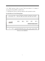
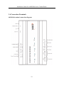
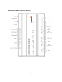
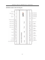
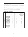
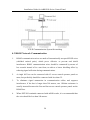
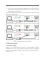
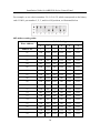
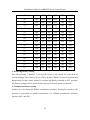
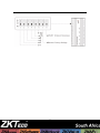
Installation Guide for inBIOX60 Series Access Control Panel Version: 1.0 Date: April, 2011 About This Manual This manual is a guide to installation and connection of the inBIOX60 series access control panel. For software using direction of the product, please refer to the user manual. Table of Contents Table of Contents 1. Important Security Instructions ........................................................... 1 1.1 Important Security Instructions ................................................. 1 1.2 Installation Cautions .................................................................. 3 2. Introduction ......................................................................................... 5 2.1 System Function Parameters ...................................................... 5 2.2 Product Technical Parameters .................................................... 6 2.3 Indicators Description ................................................................ 6 3. Connection and Installation ................................................................. 8 3.1 Panel Box Installation ................................................................ 8 3.2 Installation and Wiring .............................................................. 9 3.3 System Structure ...................................................................... 10 3.4 Connection Terminals .............................................................. 12 3.5 Connection with External Accessories..................................... 16 3.6 Connection with Readers ......................................................... 17 3.7 Relay Output Connection ........................................................ 19 3.8 System Power Supply Structure .............................................. 24 4. System Networking ........................................................................... 26 4.1 System Wiring and Wires Requirements ................................. 26 4.2 TCP/IP Network Communication ............................................ 27 4.3 RS485 Network Communication ............................................. 28 4.4 DIP Switch Settings ................................................................. 29 I 1. Important Security Instructions 1.1 Important Security Instructions 1. Read, follow and keep instructions: Before operating the equipment, read and follow strictly all security and operation instructions. Please keep the instructions for reference. 2. Accessories: Please use the accessories recommended by the manufacturer or delivered with the product. Any other related product is not recommended as the major alarming or monitoring system. The major alarming or monitoring system should comply with the local applicable fire-prevention and security standards. 3. Installation cautions: Do not place this equipment on any unstable table, tripod mount, support or base, lest the equipment should fall and get damaged, and more undesirably cause severe personal injuries. Therefore, it is important to install the equipment as instructed by the manufacturer. 4. All peripheral devices must be grounded. 5. No external connection wires can be exposed. All connections and idle wire ends must be wrapped with insulating tapes to prevent accidental contact with exposed wires from damaging the equipment. 6. Repair: Do not attempt unauthorized repair of the equipment. Disassembly or detachment is likely to cause shock or other risks. All repair jobs should be done by qualified repair personnel. 7. Damages in need of repair: In any of the following cases, first disconnect the AC/DC power supply from the equipment and notify qualified repair personnel for repairs: The power cord or connector is damaged. There is entry of liquid or any other foreign object into the equipment. 1 Installation Guide for inBIOX60 Series Control Panel The equipment is wetted or exposed to bad weather (rain, snow, etc.). If the equipment cannot work normally even though operated as instructed, please be sure to adjust only the control components specified in the operation instructions. Incorrect adjustment of other control components may cause damage to the equipment, and add to troubleshooting workload of the qualified technicians. The equipment falls down or its performance changes obviously. 8. Replacing components: If it is necessary to replace a component, the repair personnel must use only the substitutes specified by the manufacturer. 9. Security inspection: After the equipment is repaired, the repair personnel are supposed to conduct security inspection to ensure the equipment can work normally. 10. Power supply: Operate the equipment with only the type of power supply indicated on the label. Contact the operator for any uncertainty about the type of power supply. Violation of any of the following cautions is likely to lead to equipment failure, even the personal injury. Before installation, switch off the external circuit (that supplies power to the system), including lock power. Before connection the equipment to power supply, ensure the output voltage is within the specified range. Never connect power before completion of installation. 2 1.2 Installation Cautions 1. All wires must run through casing pipes, for example PVC or galvanized pipes, to prevent failure caused by rodent damage. Although a control panel is designed with good antistatic, lightning-proof, and leakage-proof functions, ensure its chassis and the AC ground wire are connected properly and the AC ground wire is grounded physically. 2. It is recommended not to plug/unplug connection terminals frequently when the system is energized. Be sure to unplug the connection terminals before starting any relevant welding job. 3. Do not detach or replace any control panel chip without permission, because unprofessional operation may cause damage to the control panel. 4. It is recommended not to connect any other auxiliary devices without permission. Before all non-routine operations, must communicate with our engineers in advance. 5. A control panel should not share one power supply with any other large-current device. 6. It is preferable to install card readers and buttons at heights of 1.4-1.5m above the ground, but the heights can be adjusted according to customers’ usual practice. 7. It is advised to install control panels at places easy of maintenance, like a weak electric well. 8. It is strongly recommended that the exposed part of any connection terminal should not be longer than 4mm, to avoid short-circuit or communication failure resulting from accidental contact with excessive exposed wires. 9. To save access control event records, download data periodically from control panels. 10. Get prepared according to application situations for unexpected power failure, like connecting power supply with UPS. 3 Installation Guide for inBIOX60 Series Control Panel 11. The connection between a card reader and a control panel should not be longer than 100 meters. 12. The connection between a PC and a control panel should be shorter than 1200m for RS485 communications. A length within 600m is recommended to make communications more stable. 13. To protect the access control system against the self-induced electromotive force generated by an electronic lock at the instant of switching off/on, it is necessary to connect a diode in parallel (please use the FR107 delivered with the system) with the electronic lock to release the self-induced electromotive force. 14. It is recommended that an electronic lock and a control panel should use respective power supplies. 15. It is recommended to use the power supply delivered with the system as the control panel power supply. 16. In a place with strong magnetic interference, galvanized steel pipes or shielded cables are recommended, and proper grounding is required. 4 2. Introduction The access control management system is a new modernized security management system, which is an effective measure for security and protection management. It is mainly used to manage entrances and exits of important places, such as banks, hotels, equipment rooms, offices, smart communities, and factories. 2.1 System Function Parameters High-speed 32-bit 400MHz CPU, 32M RAM, and 256M Flash. Embedded LINUX operating system. One-door/two-door two-way or four-door one-way access control. A maximum of 30,000 card holders and 100,000 offline event records. Support of multiple Wiegand card formats and a password keypad, compatible with various types of cards. Use of dual communication technologies: The Ethernet and the RS485 industrial bus, for reliable communications. With a watchdog (hardware) built in the control panel to prevent crash. Over-current, over-voltage, and inverse-voltage protection for input of power supply to the control panel. Over-current protection for the power supply to card readers. Instant over-voltage protection for all input/output ports. Instant over-voltage protection for communication ports. 5 Installation Guide for inBIOX60 Series Control Panel 2.2 Product Technical Parameters Working power supply: Rated voltage 12V (±20%) DC; rated current ≤0.5A. Working environment: Temperature 0°C-55°C; humidity 10%-80%. Output load: Working voltage AC ≤ 30V, rated current ≤ 8A; DC ≤ 36V, rated current ≤ 5A. C-type electronic lock relay output terminal: 10A contact current, 12V DC, with LED status indications. Output terminal of the auxiliary relay: 2A contact current, 30V DC, with LED status indications. With detachable connection terminals made of alloy-steel non-magnetic flange materials. Outline dimensions of the control panel: 185.1mm (length) × 106mm (width) × 36mm (thickness) for inBIO160/260; 226mm (length) × 106mm (width) × 36mm (thickness) for inBIO460. External box dimensions: 400mm × 330mm × 90.5mm. 2.3 Indicators Description When the inBIO160/260/460 is powered on, normally the POWER indicator (red) is lit constantly, the RUN indicator (green) flashes (indicating the system is normal), and other indicators are all off. Except the cases as follows: 1. LINK indicator (green): Light always indicates TCP/IP communication is proper; 2. ACT indicator (yellow): Flash state indicates the data is in transmitting through TCP/IP communication; 3. EXT RS485 indicator (yellow & green): Flash state indicates it is sending or receiving data through RS485 communication; 6 4. PC RS485 indicator (yellow & green): Flash state indicates it is sending or receiving data through RS485 communication; 5. CARD indicator (yellow): Flash state indicates card is punched on reader. See the indicators in the following figure: Indicators in the inBIO460 7 3. Connection and Installation 3.1 Panel Box Installation Installation steps for the control panel: Appearance and Internal of the panel box: 8 3.2 Installation and Wiring Access Control Panel Wire Installation Notes: 1. Before connection, make sure the power supply is disconnected. Any operation with power connected will cause severe damage to the equipment. 2. The access control wires must be separated according to heavy and light current; the control panel wires, electronic lock wires, and exit button wires must run through their respective casing pipes. 9 Installation Guide for inBIOX60 Series Control Panel 3.3 System Structure inBIO460 System Structure Note: The diagram above takes the inBIO460 for example. By contrast, only one-door two-way access is applicable to the inBIO160 system; only 10 two-door one-way or two-door two-way access is applicable to the inBIO260 system. The access control management system consists of two parts: Management workstation (PC) and control panel. They communicate via TCP/IP or RS485 networks. On a 485 bus, each management workstation can be connected with up to 63 inBIO control panels (preferably fewer than 32). The communication wires should be kept away from high-voltage wires as far as possible, and should be neither routed in parallel with nor bundled with power wires. A management workstation is actually a PC connected to the network. By running the access control management software installed in the PC, access control management personnel can remotely perform various management functions, like adding/deleting a user, viewing event records, opening/closing doors, and monitoring status of each door in real time. 11 Installation Guide for inBIOX60 Series Control Panel 3.4 Connection Terminals inBIO160 terminal connection diagram: 12 inBIO260 terminal connection diagram: 13 Installation Guide for inBIOX60 Series Control Panel inBIO460 terminal connection diagram: 14 Descriptions of the terminals: 1. The auxiliary input may be connected to infrared body detectors, fire alarms, smoke detectors, etc. 2. The auxiliary output may be connected to alarms, cameras, door bells, etc. 3. All the terminals mentioned above are set through relevant access control software. Please see the respective software instructions for details. Terminals on the C3 control panel: No. 1 Functional Port Wiegand card inBIO460 inBIO160 inBIO260 (One-Door (Two-Door Two-Way) Two-Way) 2 4 4 (Four-Door One-Way/Two-Door Two Way) reader interface 2 Exit button 1 2 4 3 Control lock relay 1 2 4 4 Door sensor 1 2 4 5 Extension input 1 2 4 6 Extension output 1 2 4 RS485 & PC √ √ √ √ √ √ √ √ √ 7 8 9 communication RS485 extension communication TCP/IP 15 Installation Guide for inBIOX60 Series Control Panel 3.5 Connection with External Accessories 1. Door sensor A door sensor is used to detect the open/closed status of a door. With a door sensor switch, an access control panel can detect illegal opening of a door, and will trigger an alarm. Moreover, if a door is not closed within a specified period of time after it is opened, the door control panel will also prompt an alarm. It is recommended to select two-core wires over 0.22 mm2. A door sensor may be omitted if it is unnecessary to monitor online the open/closed status of a door, trigger an alarm when the door is not closed for a long time or there is illegal access, and use the interlock function. 2. Exit button An exit button is a switch installed indoors to open a door. When you press the button, the door will be opened. An exit button is fixed at a height of about 1.4 meter above the ground. Ensure it is located in the right position without slant, and its connection is correct and secure (Cut off the exposed end of any unused wire and wrap it with insulating tape). Note to prevent the electromagnetic interference (such as light switches and computers). It is recommended to use two-core wires over 0.3mm2 as the connection wire between an exit button and a control panel. 3. Auxiliary input inBIO160 provides one auxiliary input interface; inBIO260 provides two, and inBIO460 provides four, which are connected to infrared body detectors, smoke detectors, gas detectors, window sensor alarms, wireless exit buttons, etc. Auxiliary inputs are set through relevant access control software. For details, please refer to ZKAccess5.0 User Manual. 16 Connections between inBIO460 and external accessories Note: The diagram above takes inBIO460 for example. By contrast, inBIO160 provides one auxiliary input interface; inBIO260 provides two, and inBIO460 provides four. 3.6 Connection with Readers The control panel supports inBIO biometric verification reader and Wiegand reader. 17 Installation Guide for inBIOX60 Series Control Panel In use of inBIO reader, all operations including storage, verification, etc. execute in control panel. No need to re-register the fingerprints for reader changing. Realize the real biometric reader connection. 1. Connected with inBIO readers inBIO160 can connect two inBIO readers in the one-door two-way mode. inBIO260 provides four readers, which can be connected in the two-door two-way mode. inBIO460 provides eight readers, which can be connected in the two-door two-way or four-door one-way mode. 485 reader connection: First of all, set the 485 address (device number) of reader by software, DIP switch or keypad method. Such as the reader 1, 2 (the odd number is for enter reader, and the even number is for exit reader), for example, the 485 address is 1, 2, and the door number is 1. For more information, please refer to the software user manual. Connection between inBIO460 and inBIO Readers 2. Connected with Wiegand readers inBIO160 can connect two Wiegand readers in the one-door two-way mode. inBIO260 provides four readers, which can be connected in the two-door two-way mode. inBIO460 provides four readers, which can be connected in the two-door two-way or four-door one-way mode. The Wiegand interfaces provided by the inBIO series can be connected to different 18 types of readers. If your card reader does not use the voltage of DC 12V, an external power supply is needed. A reader should be installed at a height of about 1.4 meter above the ground and at a distance of 30-50mm away from a door frame. Connection between inBIO460 and Readers 3.7 Relay Output Connection inBIO160 has two relays (by default, one used as a control lock and the other used 19 Installation Guide for inBIOX60 Series Control Panel as an auxiliary output); inBIO260 has four relays (by default, two used as control locks and the other two used as auxiliary outputs); inBIO460 has eight relays (by default, four used as control locks and the other four used as auxiliary outputs). The relays for auxiliary outputs may be connected to monitors, alarms, door bells, etc. Auxiliary outputs are set through relevant access control software. For details, please refer to ZKAccess5.0 User Manual. A lock relay can be connected in the dry and wet modes, while an auxiliary output relay cannot. The following illustrates relay output connection with an example of door connection. 1) An access control panel provides multiple electronic lock outputs. The COM and NO terminals are applicable to the locks that are unlocked when power is connected and locked when power is disconnected (that is NO lock). The COM and NC terminals are applicable to the locks that are locked when power is connected and unlocked when power is disconnected (that is NC lock). 2) By setting the jumper terminal beside the lock relay, you can select the device power supply or lock power supply for the lock (that is, the wet mode or dry mode). Dry mode jumper setting: Short 1-2 and 3-4, and the device power supply will be used for the relay output. Wet mode jumper setting: short 2-3 and 4-5, and the lock power supply will be used for the relay output. Note: The factory default jumping is set as dry mode. 3) To protect the access control system against the self-induced electromotive force generated by an electronic lock at the instant of switching off/on, it is necessary to connect a diode in parallel (please use the FR107 delivered with the system) with the electronic lock to release the self-induced electromotive force. 20 1. Wet mode: External power supply for NO Lock 2. Wet mode: External power supply for NC Lock 21 Installation Guide for inBIOX60 Series Control Panel 3. Dry mode: External power supply for NO Lock 4. Dry mode: External power supply for NC Lock 22 5. Dry mode: NO Lock under the binary value control. 6. Dry mode: NC Lock under the binary value control. 23 Installation Guide for inBIOX60 Series Control Panel 3.8 System Power Supply Structure An access control operator panel is powered by +12V DC. Generally, to reduce 24 power interference between control panels, each control panel should be powered separately. When high reliability is required, control panels and electronic locks should be powered respectively. To prevent power failure of a control panel from making the whole system unable to work normally, the access control management system is usually required to have one UPS at least, and access control locks are powered externally to guarantee the access control management system can still work normally during power failure. 25 4. System Networking 4.1 System Wiring and Wires Requirements 1. RS485 communication wires are made of internationally accepted shielded twisted pairs, which provide effective protection and shield of interference. 2. The power supply is 12V DC converted from 220V. 3. The Wiegand readers use 6-core communication shielded wires (RVVP 6×0.5mm) (usually there are 6, 8, and 10-core types available for users to select) to reduce interference during transmission. 4. As an electronic lock has a big current, it generates strong interference signal during an action. To reduce the effect of an electronic lock during an action on other elements, 4-core wires (RVV 4×0.75mm2, two for a power supply and two for door sensor) are recommended. 5. Other control cables (like exit buttons) are all made of 2-core wires (RVV 2×0.5mm2). 6. Notes for wiring: Signal wires (like network cables and RS-485 wires) can neither run in parallel with nor share one casing pipe with large-power electric wires (like electronic lock wires and power cables). If parallel wiring is unavoidable for environmental reasons, the distance must be over 50cm. Try to avoid using any wire with a connector during wiring. When a connector is indispensable, it must be crimped or welded. No mechanical force can be applied to the joint or branch of conductors. In a building, distribution lines must be installed horizontally or vertically. They should be protected in casing pipes (like plastic or iron water pipes, to be selected according to the technical requirements of indoor distribution). Metal hoses are applicable to ceiling wiring, but must be secure and good-looking. 26 Shielding measures and shielding connection: If the electromagnetic interference in the wring environment is found strong in the survey before construction, it is necessary to consider shielding protection for data cables when designing a construction scheme. Overall shielding protection is required if there is a large radioactive interference source or wiring has to be parallel with a large-current power supply on the construction site. Generally, shielding measures include: Keeping a maximum distance from any interference source, and using metal wiring troughs or galvanized metal water pipes to ensure reliable grounding of the connection between the shielding layers of data cables and the metal troughs or pipes. Note that a shielding enclosure can have a shielding effect only when it is grounded reliably. Ground wire connection method: Reliable large-diameter ground wires in compliance with applicable national standards are needed on the wiring site, and should be connected in a tree form to avoid DC loop. These ground wires must be kept far away from lightning fields. No lightning conductor can serve as a ground wire, and ensure there is no lightning current through any ground wire when there is lightning. Metal wiring troughs and pipes must be connected continuously and reliably, and linked to ground wires through large-diameter wires. The impedance of this section of wire cannot exceed 2ohm. The shielding layer also must be connected reliably, and grounded at one end to guarantee uniform current direction. The ground wire of the shielding layer must be connected through a larger wire (not smaller than 2.5mm2). 4.2 TCP/IP Network Communication The Ethernet 10/100Base-T Crossover Cable, a type of crossover network cable, is mainly used for cascade hubs and switches, or used to connect two Ethernet end-points directly (without a hub). Both 10Base-T and 100Base-T are supported. 27 Installation Guide for inBIOX60 Series Control Panel TCP/IP Communication System Networking 4.3 RS485 Network Communication 1. RS485 communication wires are made of internationally accepted RVSP wires (shielded twisted pairs), which prove effective to prevent and shield interference. RS485 communication wires should be connected by means of bus cascade instead of in a star form, to achieve a better shielding effect by reducing signal reflection during communications. 2. A single 485 bus can be connected with 63 access control operator panels at most, but preferably should be connected with less than 32. 3. To eliminate signal attenuation in communication cables and suppress interference, if the bus is longer than 300 meters, one 120ohm resistance is usually inserted between the first and last access control operator panels on the RS485 bus. 4. When EXT485 terminals connected with inBIO reader, it is recommended that the wire should be less than 100 meters. 28 5. For this access control operator panel, putting place 8 of the DIP switch to the ON position is equivalent to parallel connection of one 120ohm resistance between the 485+ and 485- lines. As shown in the figure below, put number 8 of the DIP switches of the first and last control panels to ON position. RS485 Communication System Networking 4.4 DIP Switch Settings 1. 485 address setting Number 1-6 of the DIP switch are reserved to set device number for RS485 communication. The code is binary, and the lower places are in the front. When the switch is set to ON position, it indicates 1 (on); when the switch is set downwards, it indicates 0 (off). 29 Installation Guide for inBIOX60 Series Control Panel For example, to set a device number 39=1+2+4+32, which corresponds to the binary code 111001, put number 1, 2, 3, and 6 to ON position, as illustrated below. 485 address setting table: Switch Setting Place Address 1 2 3 4 5 6 Address No. 1 2 4 8 16 32 01 ON OFF OFF OFF OFF OFF 02 OFF ON OFF OFF OFF OFF 03 ON ON OFF OFF OFF OFF 04 OFF OFF ON OFF OFF OFF 05 ON OFF ON OFF OFF OFF 06 OFF ON ON OFF OFF OFF 07 ON ON ON OFF OFF OFF 08 OFF OFF OFF ON OFF OFF 09 ON OFF OFF ON OFF OFF 10 OFF ON OFF ON OFF OFF 11 ON ON OFF ON OFF OFF 12 OFF OFF ON ON OFF OFF 13 ON OFF ON ON OFF OFF 14 OFF ON ON ON OFF OFF 15 ON ON ON ON OFF OFF 16 OFF OFF OFF OFF ON OFF 17 ON OFF OFF OFF ON OFF 18 OFF ON OFF OFF ON OFF 30 19 ON ON OFF OFF ON OFF 20 OFF OFF ON OFF ON OFF 21 ON OFF ON OFF ON OFF 22 OFF ON ON OFF ON OFF 23 ON ON ON OFF ON OFF 24 OFF OFF OFF ON ON OFF 25 ON OFF OFF ON ON OFF 26 OFF ON OFF ON ON OFF 27 ON ON OFF ON ON OFF 28 OFF OFF ON ON ON OFF 29 ON OFF ON ON ON OFF 30 OFF ON ON ON ON OFF 31 ON ON ON ON ON OFF 32 OFF OFF OFF OFF OFF ON 33 ON OFF OFF OFF OFF ON 34 OFF ON OFF OFF OFF ON 35 ON ON OFF OFF OFF ON 36 OFF OFF ON OFF OFF ON 37 ON OFF ON OFF OFF ON 38 OFF ON ON OFF OFF ON 39 ON ON ON OFF OFF ON 40 OFF OFF OFF ON OFF ON 41 ON OFF OFF ON OFF ON 42 OFF ON OFF ON OFF ON 43 ON ON OFF ON OFF ON 44 OFF OFF ON ON OFF ON 45 ON OFF ON ON OFF ON 46 OFF ON ON ON OFF ON 31 Installation Guide for inBIOX60 Series Control Panel 47 ON ON ON ON OFF ON 48 OFF OFF OFF OFF ON ON 49 ON OFF OFF OFF ON ON 50 OFF ON OFF OFF ON ON 51 ON ON OFF OFF ON ON 52 OFF OFF ON OFF ON ON 53 ON OFF ON OFF ON ON 54 OFF ON ON OFF ON ON 55 ON ON ON OFF ON ON 56 OFF OFF OFF ON ON ON 57 ON OFF OFF ON ON ON 58 OFF ON OFF ON ON ON 59 ON ON OFF ON ON ON 60 OFF OFF ON ON ON ON 61 ON OFF ON ON ON ON 62 OFF ON ON ON ON ON 63 ON ON ON ON ON ON 2. Restoring factory setting The silk-screened 7 (number 7) of the DIP switch is the switch for restoration of system settings. The switch is set to OFF by default. When it is moved upwards and downwards for three times within 10 seconds and finally returned to OFF position, the factory settings will be restored after the access control panel is restarted. 3. Terminal resistance setting Number 8 is for setting the RS485 termination resistance. Putting the switch to ON position is equivalent to parallel connection of a 120ohm termination resistance between 485+ and 485-. 32 33