1
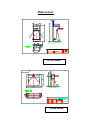
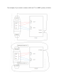
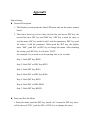
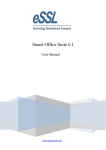
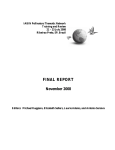
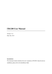
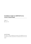
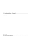
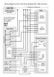
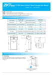
Turnstile User Manual www.esslsecurity.com Preface Thanks a lot for purchasing our tripod turnstile. These series of products with our unique functions, excellent stability, fashionable design which using the standard electrical equipment foreign interface that make it could integrating with the Magcard, Bar code, ID card and Mifare card, and it extensive apply to Government, Hotel, Factory, Club, Station and so on. The tripod turnstile has passed strict and seriously examine. Please rest assured use. Before using this machine, please read this user manual carefully in order to avoid the damage you and your product because the misoperation. eSSL , reliable brand and your best choice. Catalogue Product Presentation ··································································································································· Dimensions·································································································································································· Installation ·································································································································································· Routing Maintenance·································································································································· Recovery Processing ····································································································································· Appendix ······································································································································································· Product Presentation Description eSSL passage management system is able to fast identify the passing pedestrian by using of RFID card or biometric identification technology. The system could organically combine with computer network management and control technology and safety prevention technology, to achieve safe and orderly passing of pedestrian through the intelligent control equipment, thus establishing reasonable safety authentication, orderly access and time attendance management model. Features Made of stainless steel SUS304, which is rustproof, durable, and can resist external destroy. The gear drive makes the system more exact and reliable with low noise and no mechanical shock. Self-checking function makes the lock automatic recovery. More work mode for choice: Normally closed mode Under normal circumstances at usual time, the channel is turned off, after a pedestrian with the valid card is read, the channel gate is opened and the passage can get through smoothly. Free passage mode During the peak, the passage can freely access without reading cards. Bi-directional flow limit Cards are required to be read at both entrance and exit before they can access One-way follow limit mode While pedestrian with the card is read in one direction, the pedestrian is prohibited in the other direction; While pedestrian with the card is read in one direction, the pedestrian will be past freely in the other direction; While pedestrian are passing freely in one direction, the other direction is prohibited. Remotely operation makes the fire protection. System integrated with RFID, Bar code, Biometric and others LED Indicating Lamp Check function of the pedestrian number Technical Parameters Supply Voltage: AC110/220V±10V, 50Hz Working Temperature: -28℃ ~ 60℃ Working Humidity: <80% Maximum Channel: 600mm Passing Speed: 40/Min(RFID), 30/MIN(Fingerprint) Dynamo: 24V/25W Communication: RS485 Dimensions TS1000 Series TS2000 Series Installation Check the Accessories. Confirm the installation position according to the application. In accordance with below to confirm the hole sites which need burying four M12 screws before the installation Make the wires through the PVC spools, then burying them with the cement. ! Attention The burying PVC spools depth must greater than 60mm, and the basset PVC spools height must greater than 50mm, the export must back bending to avoid inflow water in the spools. Opening the casing door, screwing down the nuts. ! Attention 1. All the operation must under the power cutting. 2. If using outdoors, please installing higher the ground with 100-200mm to avoid the humidity and installing a covering on the top of the machine to avoid the rain. 3. Ban to crush or push the brake bar before the LED turn green when it works 4. Ban to sit or press the brake bar when it does not work. 5. Ban to push the brake bar with strong force. ! Attention Stopping using the machines on the thunder weather. Make sure connect with the ground wires. Routine Maintenance Using the soft textiles scrubbing the surface of the machines frequently, keep clean and bright. Ban to use the hard goods to scrub the surface and ban to use the water wash the machines directly. Periodic [routine] inspection for all the connection of the motion parts, if discover the looseness, please screw down the bolts or nuts in time in order to avoid the long time running make the machine broken. Periodic [routine] inspections for the connection of the ground wires and make it reliable. Periodic [routine] inspection for the connection of the wiring points and connectors and make it reliable. Recovery Processing Q: The direction indicator does not display and the reader can’t read card or fingerprint. A: The main problem is the power supply, please check whether the 3A FUSE in the master-control unit is broken, whether the connector is looseness, whether the power line is cut off. Q: The brake bar is felled when using it. A: There have two reasons make this happens 1. Two M4 hex head screws are loosened, please open the loam cake of the case then loosen the two M4 hex head screws, move up the electromagnet a little, at last fastening the screws, if still not work, please repeat the step again until it works. 2. The power of the shrapnel’s elasticity is lacked, as below Shrapnel 弹片 Q: Read the card and LED indicated display normally, but can’t pass it. A: There have three reasons make this happens 1. The 5A FUSE on the master board is broken. 2. The dynamo is broken or the wire connection is loosened. 3. The master control board is broken. For these problems please inform us to change one for you! Q: How to integrate with other access control system? A: Please check the picture below: Right Right Com Com Left Left For example, if you want to connect with our C3 or inBIO system, as below: Appendix Menu Setting General Description 1. The Display screen means the three LED nixie tube on the master control board 2. There have three keys in two lines, the first line just have a SET key, the second line have INC key and DEC key. SET key is used for entry or exit the menu, INC key used for add 1 with the parameter, DEC key used for reduce 1 with the parameter. When push the SET key, the display show “P00”, push INC or DEC key to change the menu. After finishing the setting, push SET key it will show “RUN”. For example: If you want to set the passing time is six seconds. Step 1: Push SET keyP00 Step 2: Push INC or DEC keyP03 Step 3: Push SET key010 Step 4: Push INC or DEC key006 Step 5: Push SET keyP03 Step 6: Push INC or DECP00 Step 7: Push SET keyRUN Entry and Exit the Menu 1. Entry the menu: push the SET key, heard “du”, loosen the SET key, there will be showed “P00”, push the INC or DEC key to change the menu P00: Exit the menu setting, when show “P00”, push SET key to exit the menu. P03: The passing time P04: Power for lock(000), power for unlock(000) P10: Clear the count value of entry (Left) P11: Clear the count value of Exit (Right) P12: Memory read with the passing P13: Setting the communication address P15: Recovery the system with default setting Function Explain The passing time: P03 Push SET key when showed “P03”, the effective time is 0 to 60 seconds, using INC and DEC key to change the time, then push SET key to exit, the default time is 10 seconds. Clear the count value of entry (Left): P10 When showed “P10”, push SET key then go to “C-L”, push INC key to save and exit, push SET key to cancel the operation. Clear the count value of Exit (Right): P11 When showed “P11”, push SET key then go to “C-R”, push INC key to save and exit, push SET key to cancel the operation. Setting the log: P12 When showed “P12”, push SET key, using the INC and DEC key to change the mode from 0 to 3, then push SET key to exit, the default is 0 =0 both ways with memory =1 Entry (Left) with memory =2 Exit (Right) with memory =3 both ways without memory Setting the communication address: P13 When showed “P13”, push SET key, using the INC and DEC key to change the address from 0 to 255, then push SET key to exit, the default is 0. Recovery the system with default setting: P15 When showed “P15”, push SET key then go to “P-2,” push INC key to save and exit, push SET key to cancel the operation.