1
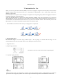
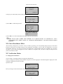
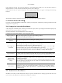
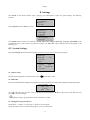
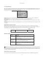
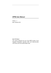
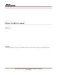
F6 Products User Manual Version: 1.1 Date: March, 2012 About This Manual This manual introduces the interface and menu operations of the F6 model of Black-White Screen product. For the product installation, see related installation guide. Contents Contents 1 Instruction for Use .......................................................................................................................................................... 1 2 Basic Concepts ................................................................................................................................................................. 3 2.1 User Enrollment.................................................................................................................................................... 3 2.2 User Verification .................................................................................................................................................. 3 2.3 Match Threshold................................................................................................................................................... 3 2.4 User ID ................................................................................................................................................................. 3 2.5 Authority Classes.................................................................................................................................................. 4 2.6 Main Interface....................................................................................................................................................... 4 3 Enrollment and Verification........................................................................................................................................... 5 3.1 Enroll User............................................................................................................................................................ 5 3.1.1 Enroll Fingerprint...................................................................................................................................... 5 3.1.2 Backup Enrollment.................................................................................................................................... 6 3.1.3 Enroll RFID Card .................................................................................................................................. 6 3.2 Check Enrollment Effect....................................................................................................................................... 7 3.3 Verification Modes ............................................................................................................................................... 7 3.3.1 Fingerprint Verification............................................................................................................................. 7 3.3.2 Verification Through Card Swiping ...................................................................................................... 8 3.4 Prompts for Successful Enrollment....................................................................................................................... 8 3.5 Administrator Enrollment ..................................................................................................................................... 8 3.6 Delete Enrollment Data ........................................................................................................................................ 9 4 Settings ........................................................................................................................................................................... 11 4.1 System Settings................................................................................................................................................... 11 4.1.1 Time Format............................................................................................................................................ 11 4.1.2 Date Time................................................................................................................................................. 11 4.1.3 Daylight Saving Time (DLST)................................................................................................................ 11 4.1.4 Language................................................................................................................................................. 12 4.1.5 Date Format............................................................................................................................................. 12 4.1.6 Advanced Settings................................................................................................................................... 14 4.2 Power Management......................................................................................................................................... 15 4.3 Communication-related Settings......................................................................................................................... 15 4.3.1 Wiegand Output ...................................................................................................................................... 16 4.4 Log Settings........................................................................................................................................................ 17 4.5 Access Options................................................................................................................................................ 17 4.5.1 Lock Driver Duration .............................................................................................................................. 18 4.5.2 Door Sensor Delay .................................................................................................................................. 18 4.5.3 Door Sensor Switch................................................................................................................................. 18 4.5.4 Door Sensor Alarm Delay ....................................................................................................................... 18 4.6 Automatic Test.................................................................................................................................................... 18 4.6.1 Flash Test ................................................................................................................................................ 19 4.6.2 LCD Test................................................................................................................................................. 19 4.6.3 Fingerprint Reader Test........................................................................................................................... 19 4.6.4 Keyboard Test ......................................................................................................................................... 19 4.6.5 Realtime Clock (RTC) Test..................................................................................................................... 19 5 SD Card Management ★............................................................................................................................................. 19 5.1 Download Attendance Data ................................................................................................................................ 19 5.2 Download Employee Data .................................................................................................................................. 20 5.3 Upload Employee Data ....................................................................................................................................... 20 6 System Information....................................................................................................................................................... 20 7 485 Reader Function ................................................................................................................................................. 21 8 Maintenance................................................................................................................................................................... 22 9 FAQs............................................................................................................................................................................... 22 10 Appendix...................................................................................................................................................................... 23 10.1 SD Card ............................................................................................................................................................ 23 10.2 ID Card, Mifare Card ................................................................................................................................... 24 10.3 Master-slave function ★ ................................................................................................................................. 24 10.4 Wiegand Protocol ............................................................................................................................................. 26 10.5 Statement on Human Rights and Privacy ......................................................................................................... 27 10.6 Environment-Friendly Use Description ............................................................................................................ 28 -I- Instruction for Use 1 Instruction for Use Thank you for using our black-and-white (B&W) screen series fingerprint recognition terminal (FRT). Please read this manual carefully before using this product for a comprehensive understanding so as to avoid causing unnecessary damages to the product. Protect the FRT from exposure to direct sunlight or strong beam as strong beam greatly affects the fingerprint collection and leads to fingerprint verification failure. Avoid using the FRT outdoors in summer. The working temperature of B&W screen series ranges from 0–40C. The heat dissipated during long-term operation may easily lead to response slowdown and verification pass rate decrease. It is recommended to use sunshades and heat sink devices for protection of the FRTs outdoors. We recommend you to use the FRT properly so as to achieve the optimal recognition effect and verification speed. 1. Install a B&W screen FRT and then enroll your fingerprint for comparison. Installation Recognition Enrollment Recognition Installation Enrollment 2. Recommended fingers Recommended fingers: The index finger, middle finger or the ring finger; the thumb and little finger are not recommended (because they are usually clumsy on the fingerprint collection screen). 3. Finger Placement 1) Proper finger placement: The finger is flat to the surface and centered in fingered guide. 2)Improper finger placement: Not flat to the surface Off-center Slanting Off-center Note: Please enroll and verify your fingerprint by using the proper finger placement mode to avoid degradation of verification performance due to improper operations. We reserve all rights for the final interpretation and modification of these rules. -1- F6 User Manual 4. LED Colors and Their Meanings B&W screen FRT works normally: The green LED blinks once every other second. Verification fails: The red LED is solid on for 3 seconds. Verification succeeds: The green LED is solid on for 3 seconds. Note: If the LED display is inconsistent with the above conditions, please contact our technical personnel. 5. About This Manual · Our products are subject to update from time to time, so our company will neither make a commitment to guarantee the consistency between the actual products and this document, nor assume any responsibility for any dispute arising out of the discrepancy between the actual technical parameters and this manual. This document is subject to change without prior notice. · The functions marked with in this manual are optional for some B&W screen series FRTs. Please refer to the actual product for the specific function description. · Picture descriptions in this manual may vary slightly from actual product. Please refer to the actual product for exact descriptions. · FRT and FRTs in this manual that means fingerprint terminal (or fingerprint device / machine) -2- Basic Concepts 2 Basic Concepts This section introduces the definitions and descriptions of the following basic concepts: User enrollment User verification Match threshold User ID Authority class The most important two functions supported by B&W screen series are user enrollment and verification. 2.1 User Enrollment A user can enroll up to 10 different fingerprints using one ID number to have multiple verification selections. Theoretically all the fingers of a user need to be enrolled so that the user can still perform fingerprint matching even if one or more of his/her fingers get cut or damaged. Generally it is recommended that a user shall enroll at least two fingerprints, for example, the index fingers of both hands, so that the user can use any of the enrolled fingerprints for recognition even if he/she forgets which fingerprint has been enrolled. 2.2 User Verification When a user presses his/her finger on the fingerprint reader, the B&W screen FRT compares the newly scanned fingerprint with a fingerprint stored in template. The fingerprint template is used to check the user fingerprint. If a user enrolls his/her fingerprints on an FRT, the user can keep attendance records on this FRT through fingerprint verification which takes about 2 seconds. Upon verification, the system displays a prompt about whether the verification succeeds or not and then stores the successful matching record in the B&W screen FRT. 2.3 Match Threshold The match threshold is set to achieve a trade-off between the possibilities of false rejection and false acceptance. The false acceptance means the fingerprint recognition device mistakes the fingerprint of user A for that of user B, while the false rejection means the fingerprint recognition device refuses to recognize an enrolled fingerprint. You can set a match threshold for all users. For fingerprints that fail to pass the verification, you can adopt the “ID + Fingerprint” verification mode (that is, 1:1 match) so that the system adopts the data set in 1:1 match threshold when matching the fingerprints. If a user’s fingers are severely worn out or damaged, lower the match threshold (see Table 3-1). Note: The false acceptance rate (FAR) and false rejection rate (FRR) mutually influence each other. Reducing the FAR will increase the FRR, and vice-versa. The default match threshold is 35 and the default 1:1 match threshold is 15. Table 3-1 lists the settings of match thresholds in different scenarios. Match Threshold FRR FAR High Medium Low Low Medium High Match threshold 1:N 45 35 25 1:1 25 15 10 2.4 User ID When enrolling fingerprints, a user will be allocated with an unused ID. When the user starts to verify his/her identity, this ID is used to associate the fingerprint feature template. You can enter the ID through the mini keyboard or other storage means, for example, the RF card (the fingerprint recognition device must be configured with the RF card reader). -3- F6 User Manual 2.5 Authority Classes The B&W screen series FRTs include four authority classes: Users: refer to those who are required to verify their identity for a purpose, for example, opening the door through the B&W screen FRT or keeping their entry/exit records. Administrators: refer to the users who are granted the right to enroll or delete users. 2.6 Main Interface The first interface displayed on the screen upon equipment power-on is referred to as the “Initial Interface”, as shown in the following figure. -4- Enrollment and Verification 3 Enrollment and Verification This chapter introduces how to enroll users on the B&W screen series. Further, it describes how to verify the validity of enrolled fingerprints. This chapter includes the following parts: Enroll users Check enrollment effects Enroll spare fingerprints Verify identity. Prompts for successful enrollment Note: To enroll a new user, you must have the authority of administrator. For details, see 2.5Authority Classes 3.1 Enroll User Everyone can enroll 10 pieces fingerprints on device, including one register fingerprint (e.g. 00098-0) and nine backup fingerprints (e.g. 00098-1~00098-9). If no administrator has been enrolled, any user has the right to enroll a new user. If an administrator has already been enrolled, you can only enroll a new user after passing the administrator verification. The RFT supports two enrollment modes that types of fingerprint and ID or Mifare card. Fingerprint enrollment mode applies to the majority of the general public with good quality fingerprints. If an administrator has already been enrolled, you need to verify the administrator identity by pressing MENU. The system then prompts you to swipe your finger for administrator verification. Note: If no administrator has been enrolled, administrator verification is not required. 3.1.1 Enroll Fingerprint 1) Select Menu → User Manage →Enroll User to display the [User Enrollment] interface. Select [Enroll FP] and press OK to display the [Enroll FP] interface. New Enroll User ID: 00001 ESC OK 2) Freely input a number (from 1–65534) in the [User ID] field. Press OK for 3 seconds to display the fingerprint enrollment interface. New Enroll 00998-0 Place Finger... Note: The last digit “0” in “000998-0” denotes the first fingerprint. ESC/Exit Notes: To the non-numeric key models, you can use the "▲" or "▼" key and the "OK" button to input the enrollment number. Operations: on the fingerprint enrollment interface → press "▲" or "▼" key to select the digit you want to enter, e.g. select the "hundreds place" → press "OK" button - press "▲" or "▼" key to select the number you want to enter →press "OK" button, then move to the "ten place", as the operation above → press "OK" button for 3 seconds to confirm the enrollment. 3) Place the same finger for three consecutive times on the fingerprint reader according to system prompts. If the enrollment succeeds, the following information is displayed: -5- F6 User Manual New Enroll 00998-0 ESC OK(Save) 4) Press OK (save) to save the enrolled fingerprint. If the enrollment fails, the system will prompt you to re-enter your user ID and restart the enrollment from Step 2. Notes: ① Steps of enroll more users are the same with those above of new enrollment. ② If you Enroll New Fingerprint, After place the fingerprint three consecutive times, the screen displayed "FP Enrolled Alrd", that means your fingerprint is repeat, you need change another finger to enrollment. New Enroll 00999-0 FP Enrolled Alrd ESC/Exit 3.1.2 Backup Enrollment Continuing the step 4) as above, If you press ESC on the [New Enroll] interface, you can cancel the new enrollment and display the [Backup Enroll] interface as shown in the following figure: Backup Enroll Continue? User ID: 00998 ESC OK New Enroll Continue? ESC OK The following steps of backup enrollment are the same with those of new enrollment, while the only difference is the “New Enroll” on the top right corner changes into “Backup Enroll”. Note: It is recommended that a long-term user should enroll at least two fingerprints. 3.1.3 Enroll RFID Card 1) Select Menu → User Manage →Enroll User to display the [User Enrollment] interface. Select [Reg RFID] and press OK to proceed. Reg RFID New Enroll? ESC OK 2) Press OK to confirm and proceed. New Enroll Show the card User ID: 00001 ESC OK 3) Input a number (from 1–65534) in the [User ID] field. Press OK to display the ID card enrollment interface. -6- Enrollment and Verification New Enroll 000001-C ESC OK(Save) 4) Swipe your card and the system reads your card number. New Enroll User ID : 00001 ESC OK 5) Press OK to confirm and proceed. New Enroll CARD: 16650449 User ID: 00001 ESC OK Note: The last digit “C” in “00010-C” denotes ID card. 6) Press OK to save the enrolled data and complete the ID card enrollment. Note: The ID card or Mifare card verification is an optional function. To customize ID / Mifare -card-capable FRT, please consult our commercial representatives or pre-sale technical support engineers. 3.2 Check Enrollment Effect After enrolling a fingerprint, you need to verify its validity by placing your corresponding finger properly on the initial interface of the FRT. If the FRT recognizes your fingerprint successfully, it proves that your fingerprint is clear and recognizable; otherwise, you need to re-enroll your fingerprint or change another finger for enrollment. If it still does not work, it proves that your fingerprints are not suitable for recognition and you need to adopt the fingerprint and password verification mode. 3.3 Verification Modes 3.3.1 Fingerprint Verification You can adopt 1:N matching modes for fingerprint identification. In the 1:N fingerprint matching mode, the FRT compares the current fingerprint collected through the fingerprint reader with all the fingerprints stored in the FRT. Operation steps: FP Verify Remove Finger Place your finger on the initial interface to display the following interface: Verify User ID: 00998 Verified! -7- F6 User Manual If the verification succeeds, the system will generate a voice announcement “Thank you!” after the above interface is displayed about 0.5 seconds, and then the following interface will be displayed: If the verification fails, the system will generate a voice announcement “Please try again!” and display the following interface: FP Verify Please Try Again. After the above interface is displayed 0.5 seconds, the system will return to the initial interface. 3.3.2 Verification Through Card Swiping If you have your ID card number enrolled in the system, you can pass the verification by swiping your ID card at the swiping area in a proper way. 3.4 Prompts for Successful Enrollment A high fingerprint enrollment quality assures quick verification speed, while a poor fingerprint enrollment quality may easily lead to false rejection and slow verification. To enhance the quality of enrolled fingerprints, refer to Table 4-1 Common Causes of Enrollment Failure or Poor Fingerprint Quality Finger is too dry or dirty Rub your fingers against your palm because rubbing yields oil. Moisturize your finger by breathing on it. Apply insufficient pressure Apply pressure lightly and evenly during the capturing process. Select fingers for enrollment Left and right index fingers or middle fingers are recommended. Select the fingers without worn-out or damaged fingerprints. Users usually select their index fingers, but if their index fingers do not have high fingerprint quality, they can select their middle fingers or ring fingers. For users with small fingers, they can opt for their thumbs. To enroll spare fingerprints, users can select fingers not prone to wear-out or damage, for example, the ring fingers. Finger placement Press your finger flatly on the fingerprint sensor and be sure that the pad (not the tip) covers as much of the sensor window as possible. Do not press your finger perpendicular to the fingerprint sensor; do not knock your finger on the sensor quickly; keep your finger still. Impact of the fingerprint image change The change of fingerprint image due to skin peeling-off or injury will affect the verification performance. If the fingerprint quality of a user is poor due to the skin peeling-off and the user cannot pass the verification one week later, the user needs to re-enroll his/her fingerprint or adopt the password verification mode. Other causes There may be a small amount of people who cannot pass the verification no matter how hard they try due to very poor fingerprint quality. In that case, you can adopt the ID + fingerprint verification mode, duly lower the 1: 1 match threshold or adopt the password verification mode. 3.5 Administrator Enrollment The B&W screen FRT provides administrator settings to prevent unauthorized users changing system data and ensure system security. The operations on administrator settings are as follows: -8- Enrollment and Verification 1) The brand new FRT does not assign any administrator, so you can press Menu to access the system directly and the following interface is displayed. Menu ►User Manage Options SD Card Sys Info Turn Off Alarm 2) Press OK to display the [User Manage] interface. User Manage Enroll User ►Enroll Admin Delete 3) Select Enroll Admin through the ▲/▼ key. Enroll Admin ►Enroll FP Reg RFID 4) Press OK to display the [Enroll Admin] interface. Admin Accredit Admin ESC OK 5) Select an enrollment mode and press OK to display the administrator enrollment interface. Administrator enrollment includes three modes: Enroll Recorder, Enroll Ordinary Admin, and Enroll Super Admin. For details, see 3.1.5 Authority Class. The enrollment mode of administrator is consistent with that of a new enrolled user. For details, see 4.1 Enroll a User. 3.6 Delete Enrollment Data To delete an enrolled user from the system, perform as follows: 1) Press Menu to access related menu item for verification, and the following interface is displayed: Menu ►User Manage Options SD Card 2) Press OK to display the [User Manage] interface. User Manage ►Enroll User Enroll Admin Delete 3) Select Delete through the ▲/▼ key. -9- F6 User Manual User Manage Enroll User Enroll Admin ►Delete 4) Press OK to display the [Delete] interface. Delete User ID: 00998 ESC OK 5) Enter a number in the [User ID] field and press OK to confirm your entry. Then delete the user according to system prompt. Note: About deleting the administrator Privilege and Clear all Data, there are such items in the "Advanced Settings" on some models of devices. for detail please refer to” 4.1.5 Advanced Settings”. Such deletions can also be executed by "Access Control Management Software ". Steps as below: Open the “ Access Control Management Software”→ Click “Basic settings” → “Device management” → “others” → “read options” at bottom (can read all data of connection machine) → “Clear Admin’ Privilege”. Deleting "All Users" can also be executed through the "Equipment Management" menu. Therefore, all depends on users' need and their actual models of Products. - 10 - Settings 4 Settings Press Menu on the initial interface. After verifying your administrative rights, the system displays the following interface. Menu User Manage ►Options Sys Info Select Options and press OK to proceed. Options ►System Opt Power Mng Comm Opt Log Opt Access Options Auto Test The Options menu contains six submenus: System Opt, Power Mng, Comm Opt, Log Opt, and GPRS (Only professional access control devices provide this setting), and Auto Test. These submenus will be described in the following part. 4.1 System Settings Select System Opt and the information displayed on the screen are shown in the following figure: System Opt ►Time Fmt 12H Date Time DLST Language Fmt ENG YY-MM-DD Adv Option 4.1.1 Time Format Set time format displayed on initial interface. Press / to set 24H or 12H. 4.1.2 Date Time Set the current date and time displayed on the FRT screen. Select Set Date Time and press OK to display the following interface. YYYY-MM-DD 24H 2011-11-08 9:36:29 ESC OK To modify date and time, place the cursor to the desired field through the ▲/▼ key, input correct date and time, and press OK to save the changes. Note: You need to press Menu key about 3seconds for confirm. 4.1.3 Daylight Saving Time (DLST) Select Menu → Options → System Opt → DLST to set the “DLST”. On the interface as shown in the following figure, you can set the DLST. - 11 - F6 User Manual DLST ↓ ►DLST Y Date Mode Mode 1 Enter DLST End DLST To enable the DLST, select Y and press OK. To disable the DLST, please select N. After enabling the DLST, you need to set the events related to the start and end of the DLST. You can set two modes for the DLST format: Mode 1 and Mode 2. In the default Mode 1, the DLST is set in the format of “Month-Day Hour: Minute”. In Mode 2, the DLST is set in the format of “Month-Week-Specific Day of the Week Hour: Minute”. The value scope of week (WS): 1 – 6. 1 means the first week, 2 the second week and so on and so forth. The value scope of day (WK): 0 – 6. 0 means Sunday, 1 means Monday and so on and so forth. Let’s take 4:00 September 1st 2011 (that is, Saturday of the first week in September 2011) as an example to illustrate these two modes: MM-DD 24H 11 -2 MM-WS-WK 10:00 11-1-3 24H 10:00 WK(0:Sun 6:Sat) ESC OK ESC Mode 1 OK Mode 2 Note: 1. If the month set in the DLST start time is later than that set in the DLST end time, the DLST will span two years, for example, the DLST starts at 2011-9-1 4: 00 and ends at 2012-4-1 4:00. 2. If you select Mode 2 and set the DLST to start on Sunday of the sixth week and current year is 2011, then the system will start the DLST at the specified time point on the last Sunday of current month in 2012 once finding out that there are only 5 weeks in current month. 3. If you set the DLST to start on Monday of the first week in September and current year is 2011, then the system will automatically start the DLST on the first Monday in current month once finding out that the first day is Tuesday instead of Monday in 2012. 4.1.4 Language This device has Chinese and English Languages. You can set the language displayed on the FRT screen. Select Language and press OK to display the language editing interface. If you select English, the information on screen will be displayed in English. System Opt Date Time ►Language ENG Fmt YY-MM-DD You can change the types of languages through the ▲/▼ key. Select a desired language and press OK. Then press ESC to exit the [System Opt] interface. When prompted to save your settings, press OK to save the settings. The system prompts you that your settings will take effective after the restart of your device. 4.1.5 Date Format You can set the date format displayed on the FRT screen. Select Menu→Options→System Opt→Format and press OK to display the format setting interface. Select a desired date format through the ▲/▼ key. The FRT supports 10 date formats: YY-MM-DD, YY/MM/DD, YY.MM.DD, MM-DD-YY, MM/DD/YY, MM.DD.YY, DD-MM-YY, DD/MM/YY, DD.MM.YY and YYYYMMDD. Select desired date format and press OK to confirm your selection. Then press ESC to exit the system settings. When prompted to save the settings, press OK and the date format of the system is modified. For example, the date formats MM/DD/YY and YY-MM-DD are displayed in the above figures on the left and right respectively. - 12 - Settings Welcome Sign-in 10:12 11/08/11 Tue Welcome Sign-in 10:12 11-11-08 Tue - 13 - F6 User Manual 4.1.6 Advanced Settings Through the advanced settings, you can perform such operations as restoring factory defaults, clearing management rights, deleting attendance records, clearing all data, setting match thresholds, as shown below: Adv Option ►Reset Opts Del All Logs Clear All Data Clr Admin Pri Show Score Match Thr 1:1 Thr Card Only Button Beep Alg Version N 45 35 N 10 Select a desired option through the ▲/▼ key, and perform settings as required. 1) Reset Opts. This option is used to restore all the settings to factory defaults. 2) Del All Logs This option is used to delete all verification records in the chip. 3) Clear All Data This option is used to delete all the enrolled fingerprints and records. 4) Clr admin pri This option is used to set all the administrators to ordinary users. 5) Show Score This option is used to set whether to display the fingerprint quality value on the top right corner of the screen. (Note: The setting of this option affects the image capture speed of the FRT.) 6) Match Threshold This option is used to set the extent of matching between an input fingerprint and that stored in templates. For details, see 2.1.3 Match Threshold. 7) 1:1 threshold This option is used to set the extent of matching between an input ID/fingerprint and that stored in templates in the ID and fingerprint identification mode. For details, see 2.1.3 Match Threshold. 8) Card Only If you select Yes, you only need to verify your ID card. If you select No, you need to verify both your ID card and fingerprint. 9) Button Beep This option is used to set the voice of press button. Select "Y" means has voice, select "N" means without voice. 10) Alg Version This option is used to set the version number of the fingerprint algorithm. Select 9 to adopt algorithm version 9.0 and 10 to adopt algorithm version 10.0. Please select the algorithm version with caution because the fingerprint templates of these two algorithm versions are incompatible. Note: some of the device will be prompted to remove the user information and attendance data when change the algorithm. So we proposed to back up user information and attendance data before change the algorithm. - 14 - Settings 4.2 Power Management Through power management, you can set the power setting and timing state switching. Power Settings Press Menu to access system menu. Select Options → Power Mng to display the following interface. Power Mng Sleep Idle Idle Min N SLP 0 The B&W screen FRT adopts an intelligent power management system and supports such functions as below: 1) Sleep This option is used to set the FRT to automatically enter sleep mode at specified time. You can wake up the FRT from sleep mode by pressing any key. The setting steps of this parameter are similar with those of timing shutdown. 2) Idle& Idle min These two options are closely associated. When Idle min is 0, the Idle function is disabled. When Idle min is a non-zero number (unit: minute), for example, 1, the system will enter a specified state if there is no operation in 1 minute. The maximum numerical value of "idle min" is 999. 4.3 Communication-related Settings Select Comm. Opt and the information displayed on the screen is shown in the following figure: Comm Opt ►BaudRate 115200 Dev Num 1 RS485 Y COMM Key 0 Wiegand Output ►User ID Baud Rate This option is used to set the baud rate for the communication between the FRT and the PC. It includes five options: 9600, 19200, 38400, 57600, and 115200. The low baud rate is recommended for the RS485 communication to achieve stable low-speed communication. Dev Num This option refers to the device ID numbered from 1 to 255. RS485 This parameter is used to set whether to adopt the RS485 for communications. To adopt the RS485, set this parameter to Y; otherwise set it to N. COMM Key When the password is set to 0, no password is required for communication; when the password is set to a non-zero value, this value is required for communication connection. - 15 - F6 User Manual 4.3.1 Wiegand Output This option is suitable for the Master-Slave and anti-passback function. F6 has Wigend Output function only, 2pcs F6 can not use this function, and it must be connecting 1pcs device which support Wigend Input functions if need use it. For detail, please refer to"10.3Master-slave function ★". Comm Opt ►Wiegand Output ►User ID Output Format Pulse Width 100 Pulse Interval 1000 Output: Refers to the contents output upon successful verification. You can select the “User ID” or “Card Number”. Wiegand Format: The system has two built-in formats Wiegand 26-bits and Wiegand 34-bits, Pulse Width: Refers to the width of the Wiegand pulse in microseconds. The default value scope of the pulse width is 1–1000. Pulse Interval: Refers to the interval of the Wiegand pulse in microseconds. The default value scope of the pulse width is 1–10000. Wiegand 26-bits Output Description The system has a built-in Wiegand 26-bits format. Press [Wiegand Format], and select “Standard Wiegand 26-bits”. The composition of the Wiegand 26-bits format contains 2 parity bits and 24 bits for output contents (“User ID” or “Card Number”). The binary code of 24-bits represent up to 16,777,216 (0–16,777,215) different values. 1 Even 2 25 26 User ID/Card Number Odd parity bit Definition of Fields: Field Meaning Even parity bit Judged from bit 2 to bit 13. The even parity bit is 1 if the character has an even number of 1 bit; otherwise, the even parity bit is 0. User ID/ Card Number(bit 2-bit 25) User ID/Card Number (Card Code, 0–16777215) Odd parity bit Judged from bit 14 to bit 25. The odd parity bit is 1 if the character has an even number of 1 bit; otherwise, the odd parity bit is 0. Bit 2 is the Most Significant Bit (MSB). Note: If the output contents exceed the scope allowed for the Wiegand format, the last several bits will be adopted and first several bits are automatically discarded. For example, the user ID 888 888 888 is 110 100 111 110 110 101 111 000 111 000 in binary format. Wiegand26 only supports 24 bits, that is, it only outputs the last 24 bits, and first 6 bits “110 100” are automatically discarded. Wiegand 34-bits Output Description The system has a built-in Wiegand 34-bits format. Press [Wiegand Format], and select “Standard Wiegand 34-bits”. - 16 - Settings The composition of the Wiegand 34-bits format contains 2 parity bits and 32 bits for output contents (“User ID” or “Card Number”). The binary code of 32-bits represent up to 4,294,967,296 (0–4,294,967,295) different values. 1 EvenParity 2 33 34 User ID/Card Number Odd parity bit Table 2 Definition of Fields Field Meaning Even parity bit Judged from bit 2 to bit 17. The even parity bit is 1 if the character has an even number of 1 bit; otherwise, the even parity bit is 0. User ID/Card Number (bit 2-bit 33) User ID/Card Number (Card Code, 0–4,294,967,295) Bit 2 is the Most Significant Bit (MSB). Odd parity bit Judged from bit 18 to bit 33. The odd parity bit is 1 if the character has an even number of 1 bit; otherwise, the odd parity bit is 0. 4.4 Log Settings Select Log Opt and the information displayed on the screen is shown in the following figure: Log Opt Alm SuperLog 99 ►Alm AttLog 99 ReCheck Min 0 1. Alarm Superlog & AttLog When the available space for storage of attendance logs reaches the specified value, the FRT automatically generates an alarm. 2. Recheck Min If a user’s attendance record already exists and the user checks in again within the specified period (unit: minute), his/her second attendance record will not be stored. Note: The device supports a maximum of 30,000 attendance records. If exceeds, the 30,001th attendance record will overwrite the first one. 4.5 Access Options The access control settings are valid for the FRTs with professional access control functions. The menu item “Access Options” is inexistent in the fingerprint time attendance machines and the devices with simple access control functions. Select Access Options and the information displayed on the screen are shown in the following figure: Access Options ► Lock DSen. Delay DSen. Mode DSen. Alarm - 17 - ▼ 6 10 NONE 30 F6 User Manual 4.5.1 Lock Driver Duration The lock driver duration refers to the duration within which the electric lock is opened upon the fingerprint verification. To set this duration, proceed as follows: Select Lock, and press OK. Then enter a desired number through the numeric pad, and press ESC to exit and save the setting. The unit of quantity for this duration is 20 ms, you can set it between 0 and 99. To disable this function, set the duration to “0”. 4.5.2 Door Sensor Delay DSen. Delay (Door Sensor Delay): indicates the delay in checking the door sensor after the door is open. If door sensor state is inconsistent with the normal state set by the door sensor switch, an alarm will be generated, and this period of time is regarded as the “door sensor delay”. To set DSen. Delay, press Menu → Options → Access Options, and then select DSen. Delay through the ▲/▼ key, as shown in the following figure: Access Options Lock ►DSen. Delay 6 10 Press OK and modify the value of DSen. Delay through the ▲/▼ key. You can set the alarm delay between 0 and 254s. 4.5.3 Door Sensor Switch The door sensor switch includes three modes: NONE: The door sensor switch is not used. NO: The lock is open as long as the door is open. NC: The lock is closed after the door is closed. To set DSen. Mode, press Menu → Options → Access Options, and then select DSen. Mode through the ▲/▼ key, as shown in the following figure: Access Options DSen. Delay ►DSen. Mode DSen.Alarm ▲ 10 NONE 30 Press OK and then switch among the door sensor switch modes through the ▲/▼ key. The door sensor switch includes three modes: NONE, NO and NC. 4.5.4 Door Sensor Alarm Delay The door sensor alarm delay refers to the delay in generating the alarm signal after a door sensor alarm is triggered. You can set the alarm delay between 0 and 254s. To set DSen.Alarm, press Menu → Options → Access Options, and then select DSen.Alarm through the ▲/▼ key, as shown in the following figure: Access Options DSen. Delay DSen. Mode ►DSen.Alarm 10 NONE 30 Press OK and modify the value of DSen.Alarm through the ▲/▼ key. 4.6 Automatic Test Select Auto Test and the information displayed on the screen is shown in the following figure: Auto Test ▼ ►Run All Test - 18 - SD Card Management ★ FLASH Test LCD Test FP Reader Key Test RTC Test Through this menu, you can test the system components. The auto test function helps troubleshoot the FRT quickly and facilitates the FRT maintenance. 4.6.1 Flash Test The FRT automatically tests whether the storage exist bad chunk. Chip is the chunk storage unit, if have bad chunk of physical damage, lost the ability to store the data. 4.6.2 LCD Test The FRT automatically tests the display effect of its LCD and check whether its LCD displays integral images. 4.6.3 Fingerprint Reader Test The FRT automatically tests whether the fingerprint reader works properly by checking. After select it, press "ok" to test, and check it whether normal. Press" ESC "to exit the test. 4.6.4 Keyboard Test The FRT tests whether every key on the keyboard works normally. Press any key on the [Keyboard Test] interface to check whether the pressed key matches the key displayed on screen. Press "ESC" to exit the test. 4.6.5 Realtime Clock (RTC) Test The FRT tests whether its clock works properly by checking the stopwatch of the clock. After select it, press "ok" to test, Press "ESC" to exit the test. 5 SD Card Management ★ Select Menu → SD Card and the information displayed on the screen is shown in the following figure: SD Card ▼ ►DwnLoad AttLog DwnLoadUser UpLoad User Update firmware You can download the attendance data, employee data, upload employee data and Update firmware with a SD Card drive. 5.1 Download Attendance Data 1. Insert a SD Card into the Card interface on the FRT. 2. Select SD Card Drive Mng and select the desired attendance data to be downloaded through the "▲/▼" key. The interface displayed is shown as follows: SD Card ▼ ►DwnLoad AttLog DwnLoad User UpLoad User Update firmware 3. Press OK to confirm your selection and start the download. The interface displayed upon successful download is shown as follows: - 19 - F6 User Manual Copy Data Suc! 4. Press ESC to return to the initial interface and then remove the SD Card pen drive. Three files X_attlog.dat (attendance records), X_oplog.dat (management records) and X_user (where “X” refers to the device ID) are stored in the USB pen drive. Tip: If the download succeeds, a prompt "Copy Data Suc" will pop up. If the system displays the prompt"Plug Pen Drive?" Please check whether the SD Card pen drive is plugged in properly. 5.2 Download Employee Data Employee data downloading is similar to the downloading of attendance records. Press ▲/▼ to select "DwnLoad User" from the "SD Card Mng" menu. The files user data (user profile) and Template.dat (fingerprint template) will be concurrently downloaded to the SD Card pen drive. 5.3 Upload Employee Data Press ▲/▼ to select "UpLoad User" from the "PenDrive Mng" menu and then press OK. The files user.dat (user profile) and Template.dat (fingerprint template) stored in the SD Card pen drive will be concurrently uploaded to the FRT. 5.4 Update Firmware SD card management ▼SD Card ▼ ►DwnLoad AttLog DwnLoad User UpLoad User Update firmware Before "update firmware", you need to insert stored the latest firmware with SD card. 6 System Information Through the Sys Info menu, you can check all information of the FRT, including the enrolled fingerprint count, enrolled users, attendance records, administration records and equipment information. On the Menu interface, select Sys Info and press OK to display the interface as shown in the following figure: Sys Info ►Enroll User Enroll FP AttLog Enroll Admin Alm SuperLog Free Space Info Dev Info 206 173 99 2 66 On the screen as shown in the figure above, you can check the User Cnt (Number of enrolled users), FP Cnt (Number of enrolled fingerprints), Att Log (Piece of attendance records), Admin Cnt (Number of enrolled administrators), Super Logs (Number of enrolled super administrators). Through Free Space Inf, you can check the free space in the storage device. Through Dev Info, you can check such information as the storage capacity, date of manufacture, serial number, manufacturer, algorithm version number and firmware version number. - 20 - 7 485 Reader Function ( 7 485 Reader Function Some Black-and-White Screen Access Control also regard as 485 reader for use. As the access control in use , all menu can operation. But as the 485 reader, can press fingerprint or swipe card only. If change any one step, must to restart the equipment can take effect. Enter ''485 Reader Function" menu, the interface displayed is shown as follows: 485 Reader Function ” ►485 Reader NO If select "485 reader" for "Yes", after restart devices, it can press fingerprint or swipe card only, all menu can not operation. Access control device and 485 reader function can be used to change to each other. If from 485 reader function to change to access control for use, should thought backdoor function(tamper switch of device back view)to operate. Operation: Press the tamper switch three times after the alarm being triggered 30 seconds, but not more than 60 seconds. Note: You can use the tamper switch to restore device number, system password, and clear administrator privileges. The user data will not be cleared. - 21 - F6 User Manual 8 Turn Off (Clear) Alarm The option Turn Off Alarm is available only after the FRT generates an alarm and is used to clear an alarm. Note: The option Turn off Alarm is available only after an alarm signal is generated. 9 Maintenance 1. Cleaning Sometimes the optical lens, keyboards and display screens need to be cleaned. Although the specific cleaning cycle is dependent upon the ambient environment where the FRT operates, the following maintenance guide might be of some help to you: Maintenance Description Item Keyboards and display screens Optical lens Cleaning Clean the keyboards or display screens when the surface of them is dirty or the screens look blurry. Please refer to the following descriptions. Do not clean the optical lens frequently. The optical lens work better with oil or grease. Clean the optical lens if they get blurry and the verification performance is affected. Please refer to the following descriptions. 2. Clean keyboards and LCD screens Before cleaning keyboards and LCD screens, power off the FRT, clean them with a piece of wet cloth or a neutral detergent and then wipe them with a piece of dry cloth. 3. Clean optical lens Follow the suggestions below to clean the optical lens after powering off the FRT: 1) Blow off the dust or dirt on the surface of the optical lens. 2) Clean the display screens with adhesive tape. Warning: Do not clean the optical lens with water or non-neutral detergents; otherwise the optical lens may be damaged. 3) Wipe the optical lens with a fine micro-fiber cloth. Be careful not to scratch the lens. If there are micro fibers left on the lens, try to blast them off after the lens get dry. 10 FAQs Question: How do I address the problem that some employees fail to pass the fingerprint verification more often than not? Answer: The following factors will make fingerprint verification hard or even impossible for some employees: . The fingerprints of some fingers wear out. . The fingers have too many wrinkles which change frequently. The skin on the fingers peels off badly. For users whose fingerprints are beyond recognition, they can delete these fingerprints and enroll them again or enroll a fingerprint of another finger. It is recommended to select fingers with good fingerprint quality (few wrinkles, no peeling-off and distinct fingerprint) for fingerprint enrollment. Press the finger flatly on the fingerprint sensor and be sure that the pad (not the tip) covers as much of the sensor window as possible. Perform fingerprint match test after finishing enrollment. It is recommended to enroll the fingerprints of several fingers as backup. Question: What are the possible causes of FRT communication failure? Answer: The possible causes are listed as follows: The setting of communication port is incorrect. The port set for communication is not the COM port actually used. The setting of the communication port baud rate of the PC is not consistent with that of the FRT. - 22 - Appendix The FRT is not connected with the power supply or the PC. The FRT is connected with the PC but not powered on. The No. of the connected terminal is incorrect. The data cable or converter is faulty. The COM port of the PC is faulty. Question: What are the possible causes of incomplete display (sometimes half-screen display) or blurred screen after the FRT is powered on? How to fix it? Answer: The possible causes are listed as follows: The main board is faulty. The LCD display is faulty. In either of the above cases, you need to contact the supplier and return the FRT for repair. Question: How can I delete a FRT administrator? Answer: Connect the FRT with a PC and establish communication between them. Select the FRT management tab, and click Delete Administrator to delete the FRT administrator. You can access the FRT menu after disconnecting the FRT with the PC. Question: Why is there a beep sound during the communication between FRT and PC? Answer: If the beep sound occurs in RS-485 communication mode, it is possible that the two communication cables of the converter are inversely connected or stuck together. Question: Why does the FRT constantly display “Please press (remove) your finger again”? How to fix it? Answer: The possible causes are as follows: There is dirt, grease or scratch on the surface of the fingerprint sensor, which may lead the fingerprint sensor to mistakenly think there is a finger pressing on the surface. Remove the dirt or grease on the surface of the fingerprint sensor with an adhesive tape. The connection cable of fingerprint sensor comes loose or disconnected. The chip of the main board is faulty. For the last two cases, contact the supplier and return the FRT for maintenance. Question: Why does a failure or error occurs when I read the attendance data while I can download fingerprint and password data properly? How to fix it? Answer: This problem may relate to the data cable, converter or the COM port setting of the PC. You may try decreasing the baud rate of the PC and FRT, for example, set it to 19200 or 9600 before reading the attendance data again. 11 Appendix The functions described in Appendix are all optional. If you need FRTs that support these functions, please consult our commercial representatives or pre-sales technical support engineers. 11.1 SD Card SD Card Host The FRT is used as the SD Card Host to externally connect with a SD Card pen drive for data exchange. The conventional fingerprint readers transfer data only through the RS232, RS485 or Ethernet. Bulk data transfer may take a long time due to the restriction of physical conditions. The SD Card far outperforms any other previous transfer modes in terms of data transfer rate. Insert the SD Card pen drive to the SD Card slot on the FRT, download data to the USB pen drive, and then connect the SD Card pen drive to a computer to import the data to the computer. For the operations of the FRT used as the SD Card host, see 5 SD Card Management ★. - 23 - F6 User Manual 11.2 ID Card, Mifare Card To accommodate the market demand for the currently popular RF cards, we have developed the FRT with built-in non-contact RF EM card reader module. This FRT supports multiple verification modes including the fingerprint verification, card verification to meet the diversified customer needs. ID Card The FRT supports ID cards with working frequency of 125 KHz and card reading distance of 2m to 5m. Mifare Card The FRT supports MIFARE non-contact smart cards with working frequency of 13.56 MHz and card reading distance of 3m to 5m. For the operations of the Mifare cards, see Mifare Card User Guide. 11.3 Master-slave function ★ Two devices, a master and a slave, both controlling the same lock, are connected by RS232/RS485/Wiegand. 1. The Applications of the Master and the Slave 1) Record storage: By default, the master status is exit and the slave status is entry. The records of entry and exit are both saved on the master. 2) Anti-Pass back function: Whether to perform the anti-pass back function is determined by the latest record of the user's entry and exit. With this function, the exit record must match the entry record. The function supports "Out", "In", "In Out", "None and save " or "None". Anti-pass back. By default, the identification status of the master is exit and that of the slave is entry, so if " out anti-pass back " has been set and when the last record of the user's entry is not "entry", the system will prompt anti-pass back refusal" and refuse to open the door if the user wants to exit. The logic is the same with "out anti-pass back" and " in out anti-pass back". For example, now A wants to exit. ① If the last record for A is not entry, the device will prompt anti-pass back refusal and refuse to open the door. ② If the last record for A is entry, after the fingerprint identification is passed, the device will open the door. 3) Alarm function If the slave is equipped with alarm function (e.g. F10), when an alarm incident occurs, the slave will forward it for the master to process. There is no such function on device that is not equipped with alarm function. 2. The Connection of the Master and the Slave Currently, three modes-RS232, Wiegand and RS485 are applicable for the connection of the master and the slave. Of the three, RS232 is less often used due to its deficiency that its connection distance is short. For example, it can be used when the master and the slave are just installed respectively inside and outside a door. Its connection principle is similar to that of RS485, which is omitted here. The Wiegand connection is widely used, most of whose devices on the market are applicable to the master and the slave. RS485, whose transmission distance is great (however it is recommended that - 24 - Appendix the distance should not be over 600 meters), applies to most occasions, but the slave must be equipped with the inBIO reader (which is used for collecting fingerprint or swiping card). If Wiegand connection is to be used, the connection and setting for anti-pass back are as follows: 1) Select model: Master machine: Machine with Wiegand in function, except for F10 Reader. Slave machine: Machine with Wiegand Out function. 2)Master-slave menu setting: This machine supports out, in, out-in, No, No and saved anti-pass back (enter Menu -> setting -> system setting -> advanced setting -> anti-pass back). 3) Modify device’s Wiegand output format: If the two devices are communicating, only Wiegand signals without device ID can be received. Enter device Menu -> Comm. Opt -> Wiegand option or enter software: Basic setting -> device management -> Wiegand, to modify “defined format” as “wiegand26 without device ID”. 4) Enroll user: The user must be on master machine and slave machine at the same time, and user PIN must be the same. Therefore, it is necessary to enroll user on master machine and slave machine at the same time. 5) Connection instruction: Wiegand communication is adopted for master machine and slave machine. Refer to the following for connection: Master Slave IND0 <-----> WD0 IND1 <-----> WD1 GND <-----> GND If RS485 connection is to be used, the connection and setting for anti-pass back are as follows: The mode of RS485 is a new application in the connection of the master and the slave. In this mode, user information, fingerprint verification, card verification and authority verification are all processed on the master and the slave is only used as a collector. Therefore, the software only needs to manage user information and record information on the master. 1) Choosing devices: The master: It must have the 485 communication function (upgrade firmware required). The slave: It must use the inBIO readers (reader only responsible for collecting fingerprint, such as F11 and SR200). 2) Setting the menu on the master: Setting the master: ①Access Menu>Settings>System Settings>Advanced Settings>Anti-pass back. The setting can be "Out", "In", "In Out", "None and save " or "None". ②Access Menu>Settings> Access Options>485 reader. If "Yes" is chosen, the master and slave function of 485 mode is started and at the same time the communication function with PC is forbidden. If "No" is chosen, the machine runs normally the communication function of PC. Setting the slave: Set the device number, identical to the master. 3) Connecting the master and the slave The master and the slave are for RS485 communication, whose connection is shown as in the figure: Master Slave 485+ <-----> 485+ 485- <-----> 485- GND <-----> GND 3. The Use of the Master and the Slave - 25 - F6 User Manual After the devices are started, the master works the same as common access control. The slave cannot verify. When a fingerprint is pressed or a card is swiped on the slave, the indicator will blink and "click, click" will sound to prompt and the verification result will be displayed on the master. 11.4 Wiegand Protocol Wiegand26 is an access control standard protocol established by the Access Control Standard Subcommittee affiliated to the Security Industry Association (SIA). It is a non-contact IC card reader interface and output protocol. Wiegand26 defines the interface between the card reader and controller used in the access control, security and other related industrial fields. Wiegand26 helps standardize the work of the card reader designers and controller manufacturers. The FRT is also designed in compliance with Wiegand26. Digital Signals Figure 1 is a sequence diagram in which the card reader sends digital signals in bit format to the access controller. In this sequence diagram, Wiegand follows the SIA’s access control standard protocol for the 26-bit Wiegand card reader (one pulse time ranges between 20us and 100us, and the pulse jump time ranges between 200us and 20ms). Data1 and Data0 are high level (larger than Voh) signals till the card reader prepares to send a data stream. The asynchronous low-level pulse (smaller than Vol) generated by the card reader is sent to the access control panel (The saw-tooth wave as shown in Figure 1) through Data1 or Data0. Data1 and Data0 pulses will neither overlap nor be generated synchronously. Table 1 lists the maximum and minimum pulse widths (a consecutive pulse) and pulse jump time (time between pulses) allowed by the F series fingerprint access control terminal. Table 1 Pulse Time Symbol Definition Tpw Tpi Typical Value of Reader Pulse Width Pulse Interval 100 µs 1 ms Figure 1 Sequence Diagram Wiegand Format The Wiegand format adopted by the FRT is the universal access control protocol. 26-Bit Wiegand Format The composition of the open de facto 26 Bit Weigand industry standard contains 8 bits for the facility code and 16 bits for the ID number field. Mathematically, these 8 facility codes allows for a total of just 256 (0 to 255) facility codes, while the 16 ID number bits allow for a total of only 65,536 (0 to 65,536) individual ID's within each facility code. 26-Bit Wiegand format is of 26 bits in length, including 2 bits for parity bits. 1 2 9 10 25 EP FC 26 CC OP Table 2 Definition of Fields Field Purpose EP Even Parity bit (EP) is judged based on field 1 to 13 bit. EP is 1 if the number of “1” is even; otherwise, EP is 0. FC(bit2-bit 9) Facility Code (0-255) Bit 2 is the Most Significant Bit (MSB). - 26 - Appendix CC (bit10-bit 25) Card Code (0-65 535). Bit10 is the MSB. The value of Odd Parity bit is determined by 14–26 bit. OP is 1 if the number of “1” is even; otherwise, OP is 0. OP Pyramid Wiegand format Several alternatives exist for customers who require more codes. The first is to switch to Keri’s standard 39 bit Pyramid format. This 39 bit Wiegand format contains 17 bits for the facility code field and 20 bits for the ID number field. Mathematically these 17 facility code bits allow for a total of 131,072 (0 to 131,071) facility codes, while the 20 ID number bits allow for a total of 1,048,576 (0 to 1,048,575) individual ID’s within each facility code. Since there are so many facility codes in the Pyramid format, a new facility code may be selected for each project. Additionally the large number of ID’s per facility code makes the Pyramid format ideal for very large projects. For added security, Keri Systems tracks credential coding to ensure that no duplication occurs. Table 3 provides a summary of the Pyramid Wiegand format. Table 3 Pyramid Wiegand Format Bit Number Bit 1 Bits 2 to 18 Bits 19 to 38 Bit 39 Meaning Even parity over bits 2 to 9 Facility code (0 to 131,071); Bit 2 is MSB ID Number (0 to 1,048,575); Bit 19 is MSB Odd parity over bits 20 to 38 Custom Wiegand Formats The second alternative is to create a custom Wiegand format. Typically, up to 64 bits are available for creating a custom Wiegand format. With certain limitations, formats with greater than 64 bits may be created. If a customer currently has a custom Wiegand format from Wiegand or from other proximity manufacturers, Keri can normally match that format. Although the customer is primarily responsible for custom format card coding, as an added benefit Keri Systems tracks card coding for additional security. Table 4 provides an example of one possible custom Wiegand format. Table 4 Example of a Custom Wiegand Format Bit Number Bit 1 Bits 2 to 9 Bits 10 to 21 Bits 22 to 43 Bit 44 Purpose Even parity over bits 2 to 22 OEM code (0 to 255); Bit 2 is MSB Facility code (0 to 4,096); Bit 10 is MSB ID Number (0 to 524,287); Bit 22 is MSB Even parity over bits 23 to 43 11.5 Statement on Human Rights and Privacy Dear Customers: Thank you for choosing the hybrid biometric products designed and manufactured by us. As a world-renowned provider of biometric technologies and services, we pay much attention to the compliance with the laws related to human rights and privacy in every country while constantly performing research and development. We hereby make the following statements: 1. All of our fingerprint recognition devices for civil use only collect the characteristic points of fingerprints instead of the fingerprint images, and therefore no privacy issues are involved. 2. The characteristic points of fingerprints collected by our products cannot be used to restore the original fingerprint images, and therefore no privacy issues are involved. 3. We, as the equipment provider, shall not be held legally accountable, directly or indirectly, for any consequences arising due to the use of our products. 4. For any dispute involving the human rights or privacy when using our products, please contact your employer directly. Our fingerprint products for police use or development tools support the collection of the original fingerprint images. As for whether such a type of fingerprint collection constitutes an infringement of your privacy, please contact the government or the final equipment provider. We, as the original equipment manufacturer, shall not be held legally accountable for any infringement arising thereof. - 27 - F6 User Manual Note: The law of the People’s Republic of China has the following regulations regarding the personal freedom: Unlawful arrest, detention or search of citizens of the People's Republic of China is prohibited; infringement of individual privacy is prohibited. The personal dignity of citizens of the People's Republic of China is inviolable. The home of citizens of the People's Republic of China is inviolable. The freedom and privacy of correspondence of citizens of the People's Republic of China are protected by law. At last we stress once again that biometrics, as an advanced recognition technology, will be applied in a lot of sectors including e-commerce, banking, insurance and legal affairs. Every year people around the globe suffer from great loss due to the insecurity of passwords. The fingerprint recognition actually provides adequate protection for your identity under a high security environment. 11.6 Environment-Friendly Use Description The Environment Friendly Use Period (EFUP) marked on this product refers to the safety period of time in which the product is used under the conditions specified in the product instructions without leakage of noxious and harmful substances. The EFUP of this product does not cover the consumable parts that need to be replaced on a regular basis such as batteries and so on. The EFUP of batteries is 5 years. Names and Concentration of Toxic and Hazardous Substances or Elements Toxic and Hazardous Substances or Elements Parts Name Chip resistor Pb Hg Cd Cr6+ PBB PBDE Chip capacitor Chip inductor Chip diode ESD components Buzzer Adapter Screws : Indicates that this toxic or hazardous substance contained in all of the homogeneous materials for this part is below the limit requirement in SJ/T11363-2006. : Indicates that this toxic or hazardous substance contained in at least one of the homogeneous materials for this part is above the limit requirement in SJ/T11363-2006. Note: 80% of the parts in this product are manufactured with non-hazardous environment-friendly materials. The hazardous substances or elements contained cannot be replaced with environment-friendly materials at present due to technical or economical constraints. - 28 -